EP4173971A1 - Emulator - Google Patents
Emulator Download PDFInfo
- Publication number
- EP4173971A1 EP4173971A1 EP22201458.1A EP22201458A EP4173971A1 EP 4173971 A1 EP4173971 A1 EP 4173971A1 EP 22201458 A EP22201458 A EP 22201458A EP 4173971 A1 EP4173971 A1 EP 4173971A1
- Authority
- EP
- European Patent Office
- Prior art keywords
- equipment module
- signal
- emulator
- automated
- automated equipment
- Prior art date
- Legal status (The legal status is an assumption and is not a legal conclusion. Google has not performed a legal analysis and makes no representation as to the accuracy of the status listed.)
- Pending
Links
Images





Classifications
-
- B—PERFORMING OPERATIONS; TRANSPORTING
- B64—AIRCRAFT; AVIATION; COSMONAUTICS
- B64F—GROUND OR AIRCRAFT-CARRIER-DECK INSTALLATIONS SPECIALLY ADAPTED FOR USE IN CONNECTION WITH AIRCRAFT; DESIGNING, MANUFACTURING, ASSEMBLING, CLEANING, MAINTAINING OR REPAIRING AIRCRAFT, NOT OTHERWISE PROVIDED FOR; HANDLING, TRANSPORTING, TESTING OR INSPECTING AIRCRAFT COMPONENTS, NOT OTHERWISE PROVIDED FOR
- B64F5/00—Designing, manufacturing, assembling, cleaning, maintaining or repairing aircraft, not otherwise provided for; Handling, transporting, testing or inspecting aircraft components, not otherwise provided for
- B64F5/60—Testing or inspecting aircraft components or systems
-
- B—PERFORMING OPERATIONS; TRANSPORTING
- B64—AIRCRAFT; AVIATION; COSMONAUTICS
- B64F—GROUND OR AIRCRAFT-CARRIER-DECK INSTALLATIONS SPECIALLY ADAPTED FOR USE IN CONNECTION WITH AIRCRAFT; DESIGNING, MANUFACTURING, ASSEMBLING, CLEANING, MAINTAINING OR REPAIRING AIRCRAFT, NOT OTHERWISE PROVIDED FOR; HANDLING, TRANSPORTING, TESTING OR INSPECTING AIRCRAFT COMPONENTS, NOT OTHERWISE PROVIDED FOR
- B64F5/00—Designing, manufacturing, assembling, cleaning, maintaining or repairing aircraft, not otherwise provided for; Handling, transporting, testing or inspecting aircraft components, not otherwise provided for
- B64F5/10—Manufacturing or assembling aircraft, e.g. jigs therefor
-
- G—PHYSICS
- G05—CONTROLLING; REGULATING
- G05B—CONTROL OR REGULATING SYSTEMS IN GENERAL; FUNCTIONAL ELEMENTS OF SUCH SYSTEMS; MONITORING OR TESTING ARRANGEMENTS FOR SUCH SYSTEMS OR ELEMENTS
- G05B17/00—Systems involving the use of models or simulators of said systems
- G05B17/02—Systems involving the use of models or simulators of said systems electric
-
- G—PHYSICS
- G05—CONTROLLING; REGULATING
- G05B—CONTROL OR REGULATING SYSTEMS IN GENERAL; FUNCTIONAL ELEMENTS OF SUCH SYSTEMS; MONITORING OR TESTING ARRANGEMENTS FOR SUCH SYSTEMS OR ELEMENTS
- G05B19/00—Program-control systems
- G05B19/02—Program-control systems electric
- G05B19/418—Total factory control, i.e. centrally controlling a plurality of machines, e.g. direct or distributed numerical control [DNC], flexible manufacturing systems [FMS], integrated manufacturing systems [IMS] or computer integrated manufacturing [CIM]
-
- G—PHYSICS
- G05—CONTROLLING; REGULATING
- G05B—CONTROL OR REGULATING SYSTEMS IN GENERAL; FUNCTIONAL ELEMENTS OF SUCH SYSTEMS; MONITORING OR TESTING ARRANGEMENTS FOR SUCH SYSTEMS OR ELEMENTS
- G05B19/00—Program-control systems
- G05B19/02—Program-control systems electric
- G05B19/418—Total factory control, i.e. centrally controlling a plurality of machines, e.g. direct or distributed numerical control [DNC], flexible manufacturing systems [FMS], integrated manufacturing systems [IMS] or computer integrated manufacturing [CIM]
- G05B19/41805—Total factory control, i.e. centrally controlling a plurality of machines, e.g. direct or distributed numerical control [DNC], flexible manufacturing systems [FMS], integrated manufacturing systems [IMS] or computer integrated manufacturing [CIM] characterised by assembly
-
- G—PHYSICS
- G05—CONTROLLING; REGULATING
- G05B—CONTROL OR REGULATING SYSTEMS IN GENERAL; FUNCTIONAL ELEMENTS OF SUCH SYSTEMS; MONITORING OR TESTING ARRANGEMENTS FOR SUCH SYSTEMS OR ELEMENTS
- G05B19/00—Program-control systems
- G05B19/02—Program-control systems electric
- G05B19/418—Total factory control, i.e. centrally controlling a plurality of machines, e.g. direct or distributed numerical control [DNC], flexible manufacturing systems [FMS], integrated manufacturing systems [IMS] or computer integrated manufacturing [CIM]
- G05B19/41885—Total factory control, i.e. centrally controlling a plurality of machines, e.g. direct or distributed numerical control [DNC], flexible manufacturing systems [FMS], integrated manufacturing systems [IMS] or computer integrated manufacturing [CIM] characterised by modeling, simulation of the manufacturing system
-
- B—PERFORMING OPERATIONS; TRANSPORTING
- B25—HAND TOOLS; PORTABLE POWER-DRIVEN TOOLS; MANIPULATORS
- B25J—MANIPULATORS; CHAMBERS PROVIDED WITH MANIPULATION DEVICES
- B25J9/00—Program-controlled manipulators
- B25J9/16—Program controls
- B25J9/1656—Program controls characterised by programming, planning systems for manipulators
- B25J9/1671—Program controls characterised by programming, planning systems for manipulators characterised by simulation, either to verify existing program or to create and verify new program, CAD/CAM oriented, graphic oriented programming systems
-
- G—PHYSICS
- G05—CONTROLLING; REGULATING
- G05B—CONTROL OR REGULATING SYSTEMS IN GENERAL; FUNCTIONAL ELEMENTS OF SUCH SYSTEMS; MONITORING OR TESTING ARRANGEMENTS FOR SUCH SYSTEMS OR ELEMENTS
- G05B2219/00—Program-control systems
- G05B2219/30—Nc systems
- G05B2219/45—Nc applications
- G05B2219/45055—Assembly
-
- G—PHYSICS
- G05—CONTROLLING; REGULATING
- G05B—CONTROL OR REGULATING SYSTEMS IN GENERAL; FUNCTIONAL ELEMENTS OF SUCH SYSTEMS; MONITORING OR TESTING ARRANGEMENTS FOR SUCH SYSTEMS OR ELEMENTS
- G05B2219/00—Program-control systems
- G05B2219/30—Nc systems
- G05B2219/45—Nc applications
- G05B2219/45071—Aircraft, airplane, ship cleaning manipulator, paint stripping
Definitions
- the present invention relates to an emulator configured to emulate an automated aircraft assembly jig supporting an aircraft assembly, an emulator system, a method of validating an automated equipment module for connecting to an automated aircraft assembly jig, and a method of operating an automated equipment module.
- the assembly of large structures typically involves the integration of a Major Assembly Jig (MAJ) with various assembly machines and tooling, and which all must work in coordination.
- MAJ Major Assembly Jig
- a first aspect of the invention provides an emulator configured to emulate an automated aircraft assembly jig supporting an aircraft assembly, the emulator connectable to an automated equipment module and configured to: send a first signal to an automated equipment module, wherein the first signal is representative of a communication to the automated equipment module; and receive a second signal from the automated equipment module representative of a communication from the automated equipment module, wherein the automated equipment module is arranged to operate autonomously on an aircraft assembly.
- An emulator able to mimic the electronic interfaces and responses of an automated aircraft assembly jig, thereby responding as though it were in the automated aircraft assembly jig itself, allows the interactions of the automated aircraft assembly jig with one or more automated equipment modules before the automated equipment modules operate on an automated aircraft assembly jig supporting an aircraft assembly. This provides more certainty to the operability of automated equipment modules before they are given access to work on an aircraft assembly. This can be particularly beneficial when the automated equipment modules are sourced from a different supplier to the automated aircraft assembly jig.
- the first signal may include a signal indicating to the automated equipment module that the automated equipment module is connected to the emulator.
- the second signal may include a signal indicating to the emulator that the emulator is connected to the automated equipment module.
- the automated equipment module may be configured to perform an action based on the first signal.
- the second signal may indicate that the action has been performed.
- the first signal may include a signal representative of an instruction to the automated equipment module to send a signal to the emulator to verify a secure connection between the automated equipment module and the emulator.
- the second signal may include a signal from the automated equipment module verifying the secure connection between the automated equipment module and the emulator.
- the first signal may include a signal representative of an instruction to acknowledge a movement of the automated aircraft assembly jig.
- the second signal may include a signal acknowledging the movement of the automated aircraft assembly jig.
- the first signal may include a signal representative of an instruction to move the automated equipment module with respect to the automated aircraft assembly jig.
- the second signal may include a signal indicating that the automated equipment module has moved with respect to the automated aircraft assembly jig.
- the movement of the automated aircraft assembly jig and/or the instruction to move the automated equipment module may include one or more of: moving a set distance; moving to a set destination; moving along a travel path; and moving at a set speed.
- the first signal may include a signal representative of an instruction to stop movement of the automated equipment module.
- the first signal includes a signal representative an entry through a perimeter of the automated aircraft assembly jig into part of the automated aircraft assembly jig.
- the first signal may include a signal representative of an emergency stop command.
- the second signal may indicate that the automated equipment module has stopped movement.
- the first signal may include a signal requesting information regarding the automated equipment module.
- the second signal may include a signal providing information regarding the automated equipment module.
- the emulator may be connectable to a plurality of automated equipment modules and prior to sending the first signal the emulator is configured to: receive a preliminary signal from a first automated equipment module; and determine a communication to be sent to a second automated equipment module, wherein the first signal is representative of a communication to the automated equipment module and is based on the preliminary signal received from the first automated equipment module.
- Validating the interaction of a plurality of automated equipment modules can be particularly beneficial, due to the added complexities in such a system.
- the preliminary signal may indicate an emergency stop button on the first automated equipment module has been activated.
- the preliminary signal may be representative of an intended movement of the first automated equipment module.
- the emulator may be configured to emulate an automated aircraft assembly jig supporting an aircraft wing assembly.
- an emulator system comprising the emulator of the first aspect and an automated equipment module, wherein, the emulator is configured to send the first signal to the automated equipment module; and wherein the automated equipment module is configured to send the second signal to the emulator.
- the automated equipment module may be one or more of: a robot, a conveyor, a lifter, or a manipulator.
- a method of validating an automated equipment module for connecting to an automated aircraft assembly jig comprising: connecting the automated equipment module to an emulator, wherein the emulator is configured to emulate an automated aircraft assembly jig; adjusting a setting of the emulator, wherein the setting is representative of a setting of the automated aircraft assembly jig; sending a first signal from the emulator to the automated equipment module representative of a communication to the automated equipment module; and receiving a second signal at the emulator from the automated equipment module representative of a communication from the automated equipment module.
- a method of operating an automated equipment module comprising the method of validating an automated equipment module of the third aspect, and further comprising subsequently connecting the automated equipment module to an automated aircraft assembly jig.
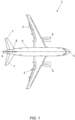
- Figure 1 illustrates a typical fixed wing aircraft 1 having a port wing 2 and starboard wing 3 carrying wing mounted engines 9.
- the wings 2, 3 extend from a fuselage 4.
- the fuselage has a nose 5 and a tail 6 with an empennage including horizontal and vertical stabiliser surfaces 7, 8.
- the aircraft 1 is a typical jet passenger transonic transport aircraft but the invention is applicable to a wide variety of fixed wing aircraft types, including commercial, military, passenger, cargo, jet, propeller, general aviation, etc. with any number of engines attached to the wings or fuselage.
- the assembly of a large section of an aircraft structure typically involves the integration of a Major Assembly Jig (MAJ) with various assembly machines and tooling, which must all work in coordination.
- MAJ Major Assembly Jig
- FIG 2 shows an automated Major Assembly Jig for fixing to an aircraft assembly 11 (i.e. an automated aircraft assembly jig 10).
- the automated assembly jig 10 may include a main frame 12 from which a plurality of stands 13 extend that assist in holding the aircraft assembly 11 in position.
- the stands 13 may suspend the aircraft assembly 10 above the ground.
- the stands 13 may allow the main frame 12, and attached aircraft assembly 11, to move vertically or horizontally, as required.
- the aircraft assembly 10 includes an aircraft wing 2,3 although it will be understood that the aircraft assembly 11 may be any suitable assembly, for example an empennage or fuselage 4 of an aircraft 1 or a combination thereof.
- the aircraft assembly 11 may be attached to the main frame 12 by one or more clamps 14 (only some of the clamps 14 are labelled in Figure 2 to increase clarity).
- the automated aircraft assembly jig 10 may include a perimeter 16 defining an assembly station and an outer boundary of the automated aircraft assembly jig 10.
- the perimeter 16 may include a physical barrier, such as a fence 16, that prevents access to or exit from the assembly station.
- the perimeter 16 may include one or more doors 18 that allow access into the assembly station.
- the assembly station may include one or more automated equipment modules 20.
- the automated equipment module 20 is arranged to operate autonomously on the aircraft assembly 11.
- FIG. 2 shows the assembly station including four automated equipment modules 20, although it will be understood that the assembly station may include any number of automated equipment modules 20.
- Each automated equipment module 20 may be any suitable automated assembly machines or robots.
- the automated equipment modules 20 may be any suitable item of equipment arranged to work autonomously on the aircraft assembly 11 inside the assembly station, such as a robot 20a, a conveyor 20b, a lifter 20c, or a manipulator 20d.
- the automated aircraft assembly jig 10 and automated equipment modules 20 all operate autonomously during assembly of the aircraft assembly 11, and must effectively communicate with each other in order to avoid collisions or other disruption to the assembly process.
- Various data is passed to and from the automated aircraft assembly jig 10 and each of the automated equipment modules 20. This helps to ensure the safety of personnel, as well as prevent damage to the aircraft assembly 11, the automated aircraft assembly jig 10, and each of the automated equipment modules 20.
- Figure 3 shows a flow chart illustrating one of many examples of the possible interactions between the automated aircraft assembly jig 10 and one or more automated equipment modules 20.
- a movement of the automated aircraft assembly jig 10 is selected. This movement may, for example, provide access to part of the aircraft assembly to an automated equipment module 20 or for inspection by assembly personnel.
- the automated aircraft assembly jig 10 verifies that the assembly station is secure 52, and in particular that all access doors 18 are closed, and that no personnel are within the perimeter 16.
- One or more assembly station scanners 19 may also be located around and/or inside the assembly station to monitor the assembly station.
- the automated aircraft assembly jig 10 sends a first signal to the automated equipment module(s) 20.
- the first signal comprises an instruction requesting each of the automated equipment module 20 to perform an action.
- the action may vary for each automated equipment module 20, for example the instruction may be to move, stop operations, or to confirm the intended actions of the automated equipment module 20 over a designated period of time.
- the automated aircraft assembly jig 10 sends the first signal and waits a designated period of time 53a for the first signal to be received by the automated equipment module 20 and for the automated equipment module 20 to confirm receipt of the first signal.
- the automated equipment module 20 receives the signal and verifies that the instruction has been received and if the instruction is actionable 54.
- the automated equipment module 20 performs the action 55.
- the automated equipment module 20 Upon completion of the action, in a subsequent step 56, the automated equipment module 20 sends a second signal that is received by the automated aircraft assembly jig 10.
- the second signal indicates that the first signal has been received by the automated equipment module 20 and that the instructed action has been performed.
- the automated aircraft assembly jig 10 fails to receive a confirmatory second signal from the automated equipment module 20 within the designated period of time 53a, the action is timed-out and the selected movement of the automated aircraft assembly jig 10 is cancelled 58.
- the automated equipment modules 20 are often sourced from different manufacturers to that of the automated aircraft assembly jig 10 and to each of the other automated equipment modules 20.
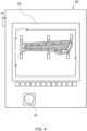
- FIG. 4 shows an example of an emulator 30 configured to emulate an automated aircraft assembly jig 10, such that the operations can be emulated in the absence of the automated aircraft assembly jig 10.
- references to emulator 30 and automated aircraft assembly jig 10 are used interchangeably unless indicated otherwise.
- the emulator 30 may include various features for interacting with a user, such as an ON/OFF switch or button 31.
- the emulator 30 may include a screen 33, such as a touch screen, configured to display a graphical representation of the automated aircraft assembly jig 10 and/or information relating to the operation of the automated aircraft assembly jig 10.
- the emulator 30 may show various information relating to the connection between the emulated automated aircraft assembly jig 10 and the automated equipment module(s) 20.
- the screen 33 may show a schematic (virtual) view of the automated aircraft assembly jig 10 and/or the automated equipment module(s) 20.
- the emulator 30 may indicate, e.g. show on the screen 33, the status of the emergency stop command or a perimeter status report.
- the emulator 30 may include a reset function that is equivalent to a reset button on the automated aircraft assembly jig 10.
- the reset function may be used to rearm the system after a safety condition (e.g. emergency stop alarm triggered, or perimeter breached).
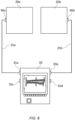
- the emulator 30 may include a connector 35, such as a Harting connector, through which a connection 25 (e.g. a data cable) can be made from the emulator 30 to a corresponding connector 36, such as a Harting connector, on an automated equipment module 20 - as shown in Figure 5 .
- a connector 35 such as a Harting connector
- a connection 25 e.g. a data cable
- a corresponding connector 36 such as a Harting connector
- the emulator 30 connects to each automated equipment module 20 using the same connector 35 (e.g. Harting connector) as the automated equipment modules 20 would connect to the actual (non-emulated) automated aircraft assembly jig 10. This ensures the connection emulates the physical connection between the automated aircraft assembly jig 10 and each automated equipment module 20 as realistically as possible.
- connector 35 e.g. Harting connector
- the signals may be compatible with the Profinet and/or Profisafe protocols.
- the signals may be adapted for transmission and receipt through the Profinet/Profisafe protocols.
- the signal exchange may require connection via a Profinet/Profisafe connector so as to be compatible with the Profinet/Profisafe standard.
- the connection may include a PN/PN coupler.
- a PN/PN coupler allows the connection of two Profinet/Profisafe networks, and transmission therebetween.
- the PN/PN coupler at each end of the connection may include a Profinet IO device that is connected to its own Profinet network.
- the emulator 30 Since the emulator 30 is intended to run as a simulator, all interactions with the automated equipment module 20 are performed through the interface of the emulator 30 (e.g. using the touch screen) without any other sensor or input device.
- the emulator 30 may be configured to send a series of test signals to the automated equipment module 20 in order to verify that the connection with the automated equipment module 20 is fully functional, and that the automated equipment module(s) 20 responds as expected.
- the emulator 30 may be connected to two or more automated equipment modules 20 (e.g. three, four, or five). This may allow the automated equipment modules 20 to be tested more efficiently, and/or test the interaction of multiple independent automated equipment modules 20 prior to working on the (physical) automated aircraft assembly jig 10.
- Figure 6 shows an example in which the emulator 30 is connected to a first automated equipment module 20a and a second automated equipment module 20b. 36.
- the emulator 30 includes a first connector 35a through which a connection 25a is made from the emulator 30 to a corresponding connector 36a on the first automated equipment module 20a. Similarly, the emulator 30 includes a second connector 35b through which a connection 25b is made from the emulator 30 to a corresponding connector 36b on the second automated equipment module 20b.
- the emulator 30 may include any number of connectors 35 for connecting to automated equipment modules 20.
- Figure 6 shows the emulator 30 including four connectors 35a, 35b, 35c, 35d, two of which (i.e. connectors 35c, 35d) remain unused in this example but in alternative examples may be connected to a third and/or fourth automated equipment module 20.
- the assembly station of the automated aircraft assembly jig 10 may include two or more work zones 37a, 37b.
- the assembly station may include a (physical or virtual) fence 38 between two sections of the assembly station.
- Figure 7 shows an example in which the assembly station is separated into a first work zone 37a and a second work zone 37b.
- the first work zone 37a includes two automated equipment modules 20a, 20b, whilst the second work zone 37b includes one automated equipment module 20c.
- the automated equipment modules 20a, 20b, 20c and sections of the automated aircraft assembly jig 10 in those respective work zones 37a, 37b may be operable independently, such that automated equipment modules 20a, 20b in the first work zone 37a are able to continue operations whilst the automated equipment modules 20c in the second work zone 37b cease operations.
- the separate and differing instructions to the automated equipment modules 20a, 20b in the first work zone 37a and the automated equipment modules 20c in the second work zone 37b may be based on any suitable parameter, as will be understood from discussion below of process and safety signals sent between the emulator 30 (emulating the automated aircraft assembly jig 10) and each automated equipment module 20.
- an intrusion into a section of the perimeter 16 belonging to the first work zone 37a, and/or an opening of a door 18a, 18b, 18c of the first work zone 37a may prompt an instruction to the automated equipment modules 20a, 20b in the first work zone 37a that is different to any instruction given to the automated equipment modules 20c in the second work zone 37b.
- an intrusion into a section of the perimeter 16 belonging to the second work zone 37b, and/or an opening of a door 18d of the second work zone 37b, may prompt an instruction to the automated equipment modules 20c in the second work zone 37b that is different to any instruction given to the automated equipment modules 20a, 20b in the first work zone 37a.
- Figure 8 shows an example of the emulator 30 emulating the separation of the assembly station of the automated aircraft assembly jig 10 into these work zones 37a, 37b.
- the fence 38 may be shown on the screen 33 along with the automated aircraft assembly jig 10 and automated equipment modules 20a, 20b, 20c.
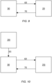
- the emulator 30 may be connectable to one or more automated equipment modules 20. This allows two-way transmission between the emulator 30 and each automated equipment module 20 so that signals 60, 70 can be sent therebetween.
- the emulator 30 is connected to the automated equipment module 20.
- the automated equipment module 20 is arranged to operate autonomously on an aircraft assembly.
- the emulator 30 sends a first signal 60 to the automated equipment module 20.
- This first signal 60 is representative of a communication to the automated equipment module 20.
- the automated equipment module 20 Upon receiving the first signal 60, the automated equipment module 20 that is connected to the emulator 30 sends a second signal 70 to the emulator 30.
- the second signal 70 is received by the emulator 30.
- the second signal 70 is representative of a communication from the automated equipment module.
- the first and second signals 60, 70 between the emulator 30 and the connected automated equipment module 20 may include any suitable communications that assist in establishing a reliable connection, and that both the automated aircraft assembly jig 10 and automated equipment module 20 would behave as expected if connected.
- the first signal 60 may include a signal indicating to the automated equipment module 20 that the automated equipment module 20 is connected to the emulator 30, and the second signal 70 may include a signal indicating to the emulator 30 that the emulator 30 is connected to the automated equipment module 20.
- the emulator 30 may involve the emulator 30 sending a continuous waveform (also referred to as a heartbeat signal) to the automated equipment module 20.
- the heartbeat signal may be sent continuously whilst a connection between the emulator 30 and the automated equipment module 20 exists, such that any disruption to the heartbeat signal represents a disruption to the connection between the emulator 30 and the automated equipment module 20.
- the heartbeat signal may be a 2 Hz square waveform.
- the automated equipment module 20 may be configured to perform an action based on the first signal 60.
- the first signal 60 may contain an instruction for the automated equipment module 20.
- the second signal 70 may indicate that the action has been performed.
- the first signal 60 may include a signal representative of an instruction to the automated equipment module 20 to send a signal to the emulator 30 to verify a secure connection between the automated equipment module 20 and the emulator 30.
- the second signal 70 may include a signal from the automated equipment module 20 verifying that there is a secure connection between the automated equipment module 20 and the emulator 30.
- the secure signals may be sent using special functions to prevent the instructions of the signals from being directly accessed, such that a function sent by the emulator 30 or automated equipment module 20 must be paired with a corresponding function at the other of the emulator 30 or automated equipment module 20 to which the signal is sent.
- the signal may not be sent until a connection between the emulator 30 and the automated equipment module 20 is verified by other (non-secure) means first, e.g. a heartbeat signal has been sent and received.
- the first signal 60 may include a signal representative of an instruction to acknowledge a movement of the automated aircraft assembly jig 10.
- the movement of the automated aircraft assembly jig 10 may include moving the automated aircraft assembly jig 10 by a set distance (for example increasing or decreasing a height of the automated aircraft assembly jig 10), moving to a set destination, moving along a travel path (e.g. the travel path may be non-linear and/or involve more than one task), moving at a set speed, or any combination thereof.
- the movement may be movement of the entire automated aircraft assembly jig 10 or a part of the automated aircraft assembly jig 10.
- the second signal 70 from the automated equipment module 20 may include a signal acknowledging the movement of the automated aircraft assembly jig 10 detailed in the first signal 60.
- the automated equipment module 20 may stop movement. Alternatively, the automated equipment module 20 may respond to the movement of the automated aircraft assembly jig 10 by moving.
- the movement of the automated equipment module 20 may include moving the automated equipment module 20 by a set distance, moving to a set destination, moving along a travel path, moving at a set speed, or any combination thereof.
- the movement of the automated equipment module 20 may alternatively or in addition include moving a part of the automated equipment module 20, for example a robot arm or a manipulator.
- the movement of the automated equipment module 20 may be reported to the automated aircraft assembly jig 10.
- the automated equipment module 20 may send information regarding the movement in the second signal 70 to the emulator 30.
- the first signal 60 may include a signal representative of an explicit instruction to move the automated equipment module 20 with respect to the automated aircraft assembly jig 10.
- the second signal 70 may include a signal indicating that the automated equipment module 20 has moved with respect to the automated aircraft assembly jig 10 as instructed by the automated aircraft assembly jig 10.
- the first signal 60 may include a signal representative of an instruction to stop movement of the automated equipment module 20.
- the second signal 70 may indicate that the automated equipment module 20 has stopped movement.
- the instruction to stop movement of the automated equipment module 20 may be determined by the status of the perimeter 16. For example, an unauthorised entry through the perimeter 16 may trigger an alarm such that the first signal 60 instructs the automated equipment module 20 to stop all activity.
- the unauthorised entry may be caused by an operator or unauthorised machinery. This helps to ensure the safety of all operators, machinery, and the aircraft assembly 11.
- the instruction to stop movement of the automated equipment module 20 may be determined by an emergency stop command.
- the emergency stop command may be triggered by an operator or other personnel, inside or outside of the assembly station.
- an emergency stop button or other interface may be triggered.
- the first signal 60 may include a signal requesting information regarding the automated equipment module 20.
- the signal may request information regarding the position and/or movement of the automated equipment module 20. This may relate to the current position and/or movement or an intended position and/or movement.
- the signal may request information to identify the automated equipment module 20 to the emulator 30 (for example: a unique ID code, name and/or model number).
- the second signal 70 may include a signal providing the requested information regarding the automated equipment module 20.
- the first signal 60 may include a signal including an error code for transmission of error or diagnostic messages from the emulator 30 to the automated equipment module 20. This may assist the emulator 30 and automated equipment module 20 to mitigate the effects of the error, and/or to diagnose a problem.
- the second signal 70 may include a signal including an error code for transmission of error or diagnostic messages from the automated equipment module 20 to the emulator 30.
- the first signal 60 may indicate a request to enter the assembly station. For example, access may have been requested by an operator at a station access door 18.
- the second signal 70 may indicate whether to it is safe to accept the request for entry to the assembly station. This may involve the automated equipment module 20 stopping movement, or moving to a safe location, which may then also be sent to the emulator 30 in the first signal 60.
- the first signal 60 may include a signal indicating to each connected automated equipment module 20 whether the assembly station is safe to work within.
- the conditions to be met may include but are not necessarily limited to: the perimeter being secure and armed, no personnel within the perimeter, no emergency stop commands triggered, each emergency stop button is armed, no assembly station scanners 19 are triggered, each assembly station scanner is armed.
- the conditions for safe working are typically considered from the perspective of the automated aircraft assembly jig 10.
- the second signal 70 may confirm receipt of the first signal 60 and/or request further information.
- the first signal 60 may include a signal requesting confirmation from the automated aircraft assembly jig 10 whether an action is safe to perform.
- the action may be a movement of the automated aircraft assembly jig 10, an operator entering the assembly station, confirmation that an emergency stop command on the automated equipment module 20 has not been triggered, or the movement of a second automated equipment module 20.
- the first signal 60 and/or second signal may include a signal requesting for a controlled disconnection between the automated equipment module 20 and the automated aircraft assembly jig 10.
- first and/or second signals 60, 70 may involve a plurality of signals.
- the automated equipment module 20 receives the first signal 60 and acts upon the first signal 60 in the same way as it would do upon receiving the first signal 60 from an automated aircraft assembly jig 10 (as opposed to an emulator 30 emulating an automated aircraft assembly jig 10).
- the emulator 30 is able to mimic the electronic interfaces and responses of an automated aircraft assembly jig 10, thereby responding as though it were in the automated aircraft assembly jig 10 itself. In this way, the emulator 30 tests the interaction with automated equipment modules 20 before they operate on a real-life aircraft assembly 11 that is being supported by the automated aircraft assembly jig 10.
- the automated aircraft assembly jig 10 will typically be connected to a plurality of automated equipment modules 20. It may therefore be necessary to emulate the interaction of multiple automated equipment modules 20.
- Figure 10 shows an example in which a first automated equipment module 20i and a second automated equipment module 20j are both connected to an emulator 30.
- the first automated equipment module 20i sends a preliminary signal 65 to the emulator 30.
- the emulator 30 receives the preliminary signal 65 and, based on the preliminary instruction, determines a communication to be sent to the second automated equipment module 20j.
- This communication may be the first signal 60, referred to in the above examples, and be based on the preliminary signal received from the first automated equipment module 20i.
- the first signal 60 may indicate a position or movement of the first automated equipment module 20i, or instruct the second automated equipment module 20j to stop movement.
- the preliminary signal 65 may indicate an emergency stop button on the first automated equipment module 20i has been activated.
- Emulation of an automated aircraft assembly jig 10 may be particularly beneficial when there will be many different automated equipment modules 20 working independently on the aircraft assembly 11, and which must work in cooperation with the automated aircraft assembly jig 10 and other automated equipment modules 20.
- An emulator 30 according to the present invention can save valuable time in validating the operation of the automated aircraft assembly jig 10 in combination with any number of automated equipment modules 20, particularly when the automated equipment modules 20 may be developed by different suppliers and therefore operate on different source code.
- the emulator 30 can be used by the supplier to validate the behaviour of the automated equipment module 20 prior to dispatch for work on the aircraft assembly 11.
- the emulator 30 may be connected to the automated equipment module 20 so that communications can be sent between the emulator 30 and the automated equipment module 20.
- a setting of the emulator 30 may then be adjusted, with that setting being representative of a setting of the automated aircraft assembly jig 10 (e.g. a change in height).
- the emulator 30 may then send a first signal 60 to the automated equipment module 20 representative of a communication to the automated equipment module 20.
- the first signal 60 is then received by the automated equipment module 20, and a second signal 70 is sent from the automated equipment module 20 to the emulator 30 that is representative of a communication from the automated equipment module 20.
- the automated equipment module(s) 20 may then subsequently be disconnected from the emulator 30 and connected to an automated aircraft assembly jig.
Landscapes
- Engineering & Computer Science (AREA)
- Manufacturing & Machinery (AREA)
- Physics & Mathematics (AREA)
- General Physics & Mathematics (AREA)
- Automation & Control Theory (AREA)
- General Engineering & Computer Science (AREA)
- Quality & Reliability (AREA)
- Transportation (AREA)
- Aviation & Aerospace Engineering (AREA)
- Automatic Assembly (AREA)
Abstract
Description
- The present invention relates to an emulator configured to emulate an automated aircraft assembly jig supporting an aircraft assembly, an emulator system, a method of validating an automated equipment module for connecting to an automated aircraft assembly jig, and a method of operating an automated equipment module.
- The assembly of large structures, such as aircraft, typically involves the integration of a Major Assembly Jig (MAJ) with various assembly machines and tooling, and which all must work in coordination.
- There is an increasing desire to provide automation of assembly processes, such that an automated MAJ may operate in tandem with various automated assembly machines and robots. In this case, various data are passed to and from the MAJ and the automated machines to ensure safety and prevent damage. However, it can be important to check and debug the signals and interfaces between the various automation parts, particularly when assembly machines and MAJ are produced by different manufacturers.
- A first aspect of the invention provides an emulator configured to emulate an automated aircraft assembly jig supporting an aircraft assembly, the emulator connectable to an automated equipment module and configured to: send a first signal to an automated equipment module, wherein the first signal is representative of a communication to the automated equipment module; and receive a second signal from the automated equipment module representative of a communication from the automated equipment module, wherein the automated equipment module is arranged to operate autonomously on an aircraft assembly.
- An emulator able to mimic the electronic interfaces and responses of an automated aircraft assembly jig, thereby responding as though it were in the automated aircraft assembly jig itself, allows the interactions of the automated aircraft assembly jig with one or more automated equipment modules before the automated equipment modules operate on an automated aircraft assembly jig supporting an aircraft assembly. This provides more certainty to the operability of automated equipment modules before they are given access to work on an aircraft assembly. This can be particularly beneficial when the automated equipment modules are sourced from a different supplier to the automated aircraft assembly jig.
- The first signal may include a signal indicating to the automated equipment module that the automated equipment module is connected to the emulator.
- The second signal may include a signal indicating to the emulator that the emulator is connected to the automated equipment module.
- The automated equipment module may be configured to perform an action based on the first signal. The second signal may indicate that the action has been performed.
- The first signal may include a signal representative of an instruction to the automated equipment module to send a signal to the emulator to verify a secure connection between the automated equipment module and the emulator.
- The second signal may include a signal from the automated equipment module verifying the secure connection between the automated equipment module and the emulator.
- The first signal may include a signal representative of an instruction to acknowledge a movement of the automated aircraft assembly jig.
- The second signal may include a signal acknowledging the movement of the automated aircraft assembly jig.
- The first signal may include a signal representative of an instruction to move the automated equipment module with respect to the automated aircraft assembly jig.
- The second signal may include a signal indicating that the automated equipment module has moved with respect to the automated aircraft assembly jig.
- The movement of the automated aircraft assembly jig and/or the instruction to move the automated equipment module may include one or more of: moving a set distance; moving to a set destination; moving along a travel path; and moving at a set speed.
- The first signal may include a signal representative of an instruction to stop movement of the automated equipment module.
- The first signal includes a signal representative an entry through a perimeter of the automated aircraft assembly jig into part of the automated aircraft assembly jig.
- The first signal may include a signal representative of an emergency stop command.
- The second signal may indicate that the automated equipment module has stopped movement.
- The first signal may include a signal requesting information regarding the automated equipment module.
- The second signal may include a signal providing information regarding the automated equipment module.
- The emulator may be connectable to a plurality of automated equipment modules and prior to sending the first signal the emulator is configured to: receive a preliminary signal from a first automated equipment module; and determine a communication to be sent to a second automated equipment module, wherein the first signal is representative of a communication to the automated equipment module and is based on the preliminary signal received from the first automated equipment module.
- Validating the interaction of a plurality of automated equipment modules can be particularly beneficial, due to the added complexities in such a system.
- The preliminary signal may indicate an emergency stop button on the first automated equipment module has been activated.
- The preliminary signal may be representative of an intended movement of the first automated equipment module.
- The emulator may be configured to emulate an automated aircraft assembly jig supporting an aircraft wing assembly.
- According to a second aspect of the invention, there is provided an emulator system comprising the emulator of the first aspect and an automated equipment module, wherein, the emulator is configured to send the first signal to the automated equipment module; and wherein the automated equipment module is configured to send the second signal to the emulator.
- The automated equipment module may be one or more of: a robot, a conveyor, a lifter, or a manipulator.
- According to a third aspect of the invention, there is provided a method of validating an automated equipment module for connecting to an automated aircraft assembly jig, the method comprising: connecting the automated equipment module to an emulator, wherein the emulator is configured to emulate an automated aircraft assembly jig; adjusting a setting of the emulator, wherein the setting is representative of a setting of the automated aircraft assembly jig; sending a first signal from the emulator to the automated equipment module representative of a communication to the automated equipment module; and receiving a second signal at the emulator from the automated equipment module representative of a communication from the automated equipment module.
- According to a further aspect of the invention, there is provided a method of operating an automated equipment module, comprising the method of validating an automated equipment module of the third aspect, and further comprising subsequently connecting the automated equipment module to an automated aircraft assembly jig.
- Embodiments of the invention will now be described with reference to the accompanying drawings, in which:
-
Figure 1 shows a typical fixed wing aircraft; -
Figure 2 shows an assembly station of an automated aircraft assembly jig; -
Figure 3 shows a flow chart of an example interaction between an automated aircraft assembly jig and automated equipment modules; -
Figure 4 an emulator for connecting to an automated equipment module; -
Figure 5 shows an emulator connected to an automated equipment module; -
Figure 6 shows an emulator connected to two automated equipment modules; -
Figure 7 shows an assembly station separated into two work zones; -
Figure 8 shows an emulator displaying the two work zones; -
Figure 9 shows an emulator and an automated equipment module exchanging signals; -
Figure 10 shows an emulator communicating with two automated equipment modules. -
Figure 1 illustrates a typicalfixed wing aircraft 1 having aport wing 2 andstarboard wing 3 carrying wing mountedengines 9. Thewings fuselage 4. The fuselage has anose 5 and atail 6 with an empennage including horizontal andvertical stabiliser surfaces aircraft 1 is a typical jet passenger transonic transport aircraft but the invention is applicable to a wide variety of fixed wing aircraft types, including commercial, military, passenger, cargo, jet, propeller, general aviation, etc. with any number of engines attached to the wings or fuselage. - The assembly of a large section of an aircraft structure, such as an
aircraft wing -
Figure 2 shows an automated Major Assembly Jig for fixing to an aircraft assembly 11 (i.e. an automated aircraft assembly jig 10). Theautomated assembly jig 10 may include amain frame 12 from which a plurality ofstands 13 extend that assist in holding theaircraft assembly 11 in position. For example, thestands 13 may suspend theaircraft assembly 10 above the ground. Thestands 13 may allow themain frame 12, and attachedaircraft assembly 11, to move vertically or horizontally, as required. - In
Figure 2 theaircraft assembly 10 includes anaircraft wing aircraft assembly 11 may be any suitable assembly, for example an empennage orfuselage 4 of anaircraft 1 or a combination thereof. Theaircraft assembly 11 may be attached to themain frame 12 by one or more clamps 14 (only some of theclamps 14 are labelled inFigure 2 to increase clarity). - The automated
aircraft assembly jig 10 may include aperimeter 16 defining an assembly station and an outer boundary of the automatedaircraft assembly jig 10. Theperimeter 16 may include a physical barrier, such as afence 16, that prevents access to or exit from the assembly station. Theperimeter 16 may include one ormore doors 18 that allow access into the assembly station. - The assembly station may include one or more
automated equipment modules 20. Theautomated equipment module 20 is arranged to operate autonomously on theaircraft assembly 11. -
Figure 2 shows the assembly station including fourautomated equipment modules 20, although it will be understood that the assembly station may include any number ofautomated equipment modules 20. - Each
automated equipment module 20 may be any suitable automated assembly machines or robots. Theautomated equipment modules 20 may be any suitable item of equipment arranged to work autonomously on theaircraft assembly 11 inside the assembly station, such as arobot 20a, aconveyor 20b, alifter 20c, or amanipulator 20d. - The automated
aircraft assembly jig 10 andautomated equipment modules 20 all operate autonomously during assembly of theaircraft assembly 11, and must effectively communicate with each other in order to avoid collisions or other disruption to the assembly process. Various data is passed to and from the automatedaircraft assembly jig 10 and each of theautomated equipment modules 20. This helps to ensure the safety of personnel, as well as prevent damage to theaircraft assembly 11, the automatedaircraft assembly jig 10, and each of theautomated equipment modules 20. -
Figure 3 shows a flow chart illustrating one of many examples of the possible interactions between the automatedaircraft assembly jig 10 and one or moreautomated equipment modules 20. - In a
first step 51, a movement of the automatedaircraft assembly jig 10 is selected. This movement may, for example, provide access to part of the aircraft assembly to anautomated equipment module 20 or for inspection by assembly personnel. - The automated
aircraft assembly jig 10 verifies that the assembly station is secure 52, and in particular that allaccess doors 18 are closed, and that no personnel are within theperimeter 16. One or moreassembly station scanners 19 may also be located around and/or inside the assembly station to monitor the assembly station. - In a
subsequent step 53, the automatedaircraft assembly jig 10 sends a first signal to the automated equipment module(s) 20. The first signal comprises an instruction requesting each of theautomated equipment module 20 to perform an action. The action may vary for eachautomated equipment module 20, for example the instruction may be to move, stop operations, or to confirm the intended actions of theautomated equipment module 20 over a designated period of time. - The automated
aircraft assembly jig 10 sends the first signal and waits a designated period oftime 53a for the first signal to be received by theautomated equipment module 20 and for theautomated equipment module 20 to confirm receipt of the first signal. - The
automated equipment module 20 receives the signal and verifies that the instruction has been received and if the instruction is actionable 54. - If the instruction is actionable, the
automated equipment module 20 performs the action 55. - Upon completion of the action, in a
subsequent step 56, theautomated equipment module 20 sends a second signal that is received by the automatedaircraft assembly jig 10. The second signal indicates that the first signal has been received by theautomated equipment module 20 and that the instructed action has been performed. - Upon receipt of the second signal the automated
aircraft assembly jig 10 moves to the selectedposition 57. - If, after sending the first signal, the automated
aircraft assembly jig 10 fails to receive a confirmatory second signal from theautomated equipment module 20 within the designated period oftime 53a, the action is timed-out and the selected movement of the automatedaircraft assembly jig 10 is cancelled 58. - It will be understood that the above example is only exemplary, and that the action could be any of a number of actions, as will become clear from the discussion below.
- Due to the complex range of operations often required on an
aircraft assembly 11, theautomated equipment modules 20 are often sourced from different manufacturers to that of the automatedaircraft assembly jig 10 and to each of the otherautomated equipment modules 20. - Even when a detailed specification of the interface signals is provided to the various manufacturer's, there remains some uncertainty due to the risk of bugs in the signals and interfaces. This can complicate and delay the setup of an automated
aircraft assembly jig 10, as it is important to ensure that the automatedaircraft assembly jig 10 andautomated equipment modules 20 operate simultaneously and seamlessly. This can protect personnel, as well as protect the automatedaircraft assembly jig 10, automatedequipment modules 20, andaircraft assembly 11. -
Figure 4 shows an example of anemulator 30 configured to emulate an automatedaircraft assembly jig 10, such that the operations can be emulated in the absence of the automatedaircraft assembly jig 10. In the following, it will be understood that references toemulator 30 and automatedaircraft assembly jig 10 are used interchangeably unless indicated otherwise. - The
emulator 30 may include various features for interacting with a user, such as an ON/OFF switch orbutton 31. Theemulator 30 may include ascreen 33, such as a touch screen, configured to display a graphical representation of the automatedaircraft assembly jig 10 and/or information relating to the operation of the automatedaircraft assembly jig 10. - The
emulator 30 may show various information relating to the connection between the emulated automatedaircraft assembly jig 10 and the automated equipment module(s) 20. For instance, thescreen 33 may show a schematic (virtual) view of the automatedaircraft assembly jig 10 and/or the automated equipment module(s) 20. Theemulator 30 may indicate, e.g. show on thescreen 33, the status of the emergency stop command or a perimeter status report. - The
emulator 30 may include a reset function that is equivalent to a reset button on the automatedaircraft assembly jig 10. The reset function may be used to rearm the system after a safety condition (e.g. emergency stop alarm triggered, or perimeter breached). - The
emulator 30 may include aconnector 35, such as a Harting connector, through which a connection 25 (e.g. a data cable) can be made from theemulator 30 to a correspondingconnector 36, such as a Harting connector, on an automated equipment module 20 - as shown inFigure 5 . - The
emulator 30 connects to eachautomated equipment module 20 using the same connector 35 (e.g. Harting connector) as theautomated equipment modules 20 would connect to the actual (non-emulated) automatedaircraft assembly jig 10. This ensures the connection emulates the physical connection between the automatedaircraft assembly jig 10 and eachautomated equipment module 20 as realistically as possible. - Once both
emulator 30 andautomated equipment module 20 are powered up, various automatedaircraft assembly jig 10 settings are adjusted, resulting in the signals being sent to theautomated equipment module 20, allowing theautomated equipment module 20 to respond according. - The signals may be compatible with the Profinet and/or Profisafe protocols. In other words, the signals may be adapted for transmission and receipt through the Profinet/Profisafe protocols. For example, the signal exchange may require connection via a Profinet/Profisafe connector so as to be compatible with the Profinet/Profisafe standard.
- The connection may include a PN/PN coupler. A PN/PN coupler allows the connection of two Profinet/Profisafe networks, and transmission therebetween. The PN/PN coupler at each end of the connection may include a Profinet IO device that is connected to its own Profinet network.
- Since the
emulator 30 is intended to run as a simulator, all interactions with theautomated equipment module 20 are performed through the interface of the emulator 30 (e.g. using the touch screen) without any other sensor or input device. - The
emulator 30 may be configured to send a series of test signals to theautomated equipment module 20 in order to verify that the connection with theautomated equipment module 20 is fully functional, and that the automated equipment module(s) 20 responds as expected. - In some examples, the
emulator 30 may be connected to two or more automated equipment modules 20 (e.g. three, four, or five). This may allow theautomated equipment modules 20 to be tested more efficiently, and/or test the interaction of multiple independentautomated equipment modules 20 prior to working on the (physical) automatedaircraft assembly jig 10. -
Figure 6 shows an example in which theemulator 30 is connected to a firstautomated equipment module 20a and a second automated equipment module 20b. 36. - The
emulator 30 includes afirst connector 35a through which aconnection 25a is made from theemulator 30 to acorresponding connector 36a on the firstautomated equipment module 20a. Similarly, theemulator 30 includes asecond connector 35b through which aconnection 25b is made from theemulator 30 to acorresponding connector 36b on the secondautomated equipment module 20b. - The
emulator 30 may include any number ofconnectors 35 for connecting toautomated equipment modules 20. For example,Figure 6 shows theemulator 30 including fourconnectors connectors automated equipment module 20. - The assembly station of the automated
aircraft assembly jig 10 may include two ormore work zones fence 38 between two sections of the assembly station. -
Figure 7 shows an example in which the assembly station is separated into afirst work zone 37a and asecond work zone 37b. Thefirst work zone 37a includes twoautomated equipment modules second work zone 37b includes oneautomated equipment module 20c. - The
automated equipment modules aircraft assembly jig 10 in thoserespective work zones automated equipment modules first work zone 37a are able to continue operations whilst theautomated equipment modules 20c in thesecond work zone 37b cease operations. - The separate and differing instructions to the
automated equipment modules first work zone 37a and theautomated equipment modules 20c in thesecond work zone 37b may be based on any suitable parameter, as will be understood from discussion below of process and safety signals sent between the emulator 30 (emulating the automated aircraft assembly jig 10) and eachautomated equipment module 20. For example, an intrusion into a section of theperimeter 16 belonging to thefirst work zone 37a, and/or an opening of adoor first work zone 37a, may prompt an instruction to theautomated equipment modules first work zone 37a that is different to any instruction given to theautomated equipment modules 20c in thesecond work zone 37b. Similarly, an intrusion into a section of theperimeter 16 belonging to thesecond work zone 37b, and/or an opening of adoor 18d of thesecond work zone 37b, may prompt an instruction to theautomated equipment modules 20c in thesecond work zone 37b that is different to any instruction given to theautomated equipment modules first work zone 37a. -
Figure 8 shows an example of theemulator 30 emulating the separation of the assembly station of the automatedaircraft assembly jig 10 into thesework zones fence 38 may be shown on thescreen 33 along with the automatedaircraft assembly jig 10 andautomated equipment modules - As shown in the previous figures, the
emulator 30 may be connectable to one or moreautomated equipment modules 20. This allows two-way transmission between the emulator 30 and eachautomated equipment module 20 so that signals 60, 70 can be sent therebetween. - The
emulator 30 is connected to theautomated equipment module 20. Theautomated equipment module 20 is arranged to operate autonomously on an aircraft assembly. - As shown in
Figure 9 , theemulator 30 sends afirst signal 60 to theautomated equipment module 20. Thisfirst signal 60 is representative of a communication to theautomated equipment module 20. - Upon receiving the
first signal 60, theautomated equipment module 20 that is connected to theemulator 30 sends asecond signal 70 to theemulator 30. Thesecond signal 70 is received by theemulator 30. Thesecond signal 70 is representative of a communication from the automated equipment module. - The first and
second signals automated equipment module 20 may include any suitable communications that assist in establishing a reliable connection, and that both the automatedaircraft assembly jig 10 andautomated equipment module 20 would behave as expected if connected. - The
first signal 60 may include a signal indicating to theautomated equipment module 20 that theautomated equipment module 20 is connected to theemulator 30, and thesecond signal 70 may include a signal indicating to theemulator 30 that theemulator 30 is connected to theautomated equipment module 20. - This may involve the
emulator 30 sending a continuous waveform (also referred to as a heartbeat signal) to theautomated equipment module 20. The heartbeat signal may be sent continuously whilst a connection between the emulator 30 and theautomated equipment module 20 exists, such that any disruption to the heartbeat signal represents a disruption to the connection between the emulator 30 and theautomated equipment module 20. In some examples, the heartbeat signal may be a 2 Hz square waveform. - The
automated equipment module 20 may be configured to perform an action based on thefirst signal 60. For example, thefirst signal 60 may contain an instruction for theautomated equipment module 20. In this case, thesecond signal 70 may indicate that the action has been performed. - The
first signal 60 may include a signal representative of an instruction to theautomated equipment module 20 to send a signal to theemulator 30 to verify a secure connection between theautomated equipment module 20 and theemulator 30. Thesecond signal 70 may include a signal from theautomated equipment module 20 verifying that there is a secure connection between theautomated equipment module 20 and theemulator 30. - The secure signals may be sent using special functions to prevent the instructions of the signals from being directly accessed, such that a function sent by the
emulator 30 orautomated equipment module 20 must be paired with a corresponding function at the other of theemulator 30 orautomated equipment module 20 to which the signal is sent. In some examples, the signal may not be sent until a connection between the emulator 30 and theautomated equipment module 20 is verified by other (non-secure) means first, e.g. a heartbeat signal has been sent and received. - The
first signal 60 may include a signal representative of an instruction to acknowledge a movement of the automatedaircraft assembly jig 10. The movement of the automatedaircraft assembly jig 10 may include moving the automatedaircraft assembly jig 10 by a set distance (for example increasing or decreasing a height of the automated aircraft assembly jig 10), moving to a set destination, moving along a travel path (e.g. the travel path may be non-linear and/or involve more than one task), moving at a set speed, or any combination thereof. The movement may be movement of the entire automatedaircraft assembly jig 10 or a part of the automatedaircraft assembly jig 10. Thesecond signal 70 from theautomated equipment module 20 may include a signal acknowledging the movement of the automatedaircraft assembly jig 10 detailed in thefirst signal 60. - In addition to acknowledging the movement of the automated
aircraft assembly jig 10, theautomated equipment module 20 may stop movement. Alternatively, theautomated equipment module 20 may respond to the movement of the automatedaircraft assembly jig 10 by moving. The movement of theautomated equipment module 20 may include moving theautomated equipment module 20 by a set distance, moving to a set destination, moving along a travel path, moving at a set speed, or any combination thereof. The movement of theautomated equipment module 20 may alternatively or in addition include moving a part of theautomated equipment module 20, for example a robot arm or a manipulator. - The movement of the
automated equipment module 20 may be reported to the automatedaircraft assembly jig 10. For example, theautomated equipment module 20 may send information regarding the movement in thesecond signal 70 to theemulator 30. - Alternatively, or in addition, the
first signal 60 may include a signal representative of an explicit instruction to move theautomated equipment module 20 with respect to the automatedaircraft assembly jig 10. In this case, thesecond signal 70 may include a signal indicating that theautomated equipment module 20 has moved with respect to the automatedaircraft assembly jig 10 as instructed by the automatedaircraft assembly jig 10. - In some examples, the
first signal 60 may include a signal representative of an instruction to stop movement of theautomated equipment module 20. Thesecond signal 70 may indicate that theautomated equipment module 20 has stopped movement. - The instruction to stop movement of the
automated equipment module 20 may be determined by the status of theperimeter 16. For example, an unauthorised entry through theperimeter 16 may trigger an alarm such that thefirst signal 60 instructs theautomated equipment module 20 to stop all activity. The unauthorised entry may be caused by an operator or unauthorised machinery. This helps to ensure the safety of all operators, machinery, and theaircraft assembly 11. - Alternatively, or in addition, the instruction to stop movement of the
automated equipment module 20 may be determined by an emergency stop command. The emergency stop command may be triggered by an operator or other personnel, inside or outside of the assembly station. For example, an emergency stop button or other interface may be triggered. - In some examples, the
first signal 60 may include a signal requesting information regarding theautomated equipment module 20. The signal may request information regarding the position and/or movement of theautomated equipment module 20. This may relate to the current position and/or movement or an intended position and/or movement. The signal may request information to identify theautomated equipment module 20 to the emulator 30 (for example: a unique ID code, name and/or model number). Thesecond signal 70 may include a signal providing the requested information regarding theautomated equipment module 20. - The
first signal 60 may include a signal including an error code for transmission of error or diagnostic messages from theemulator 30 to theautomated equipment module 20. This may assist theemulator 30 andautomated equipment module 20 to mitigate the effects of the error, and/or to diagnose a problem. Similarly, thesecond signal 70 may include a signal including an error code for transmission of error or diagnostic messages from theautomated equipment module 20 to theemulator 30. - The
first signal 60 may indicate a request to enter the assembly station. For example, access may have been requested by an operator at astation access door 18. Thesecond signal 70 may indicate whether to it is safe to accept the request for entry to the assembly station. This may involve theautomated equipment module 20 stopping movement, or moving to a safe location, which may then also be sent to theemulator 30 in thefirst signal 60. - The
first signal 60 may include a signal indicating to each connectedautomated equipment module 20 whether the assembly station is safe to work within. The conditions to be met may include but are not necessarily limited to: the perimeter being secure and armed, no personnel within the perimeter, no emergency stop commands triggered, each emergency stop button is armed, noassembly station scanners 19 are triggered, each assembly station scanner is armed. The conditions for safe working are typically considered from the perspective of the automatedaircraft assembly jig 10. Thesecond signal 70 may confirm receipt of thefirst signal 60 and/or request further information. - The
first signal 60 may include a signal requesting confirmation from the automatedaircraft assembly jig 10 whether an action is safe to perform. The action may be a movement of the automatedaircraft assembly jig 10, an operator entering the assembly station, confirmation that an emergency stop command on theautomated equipment module 20 has not been triggered, or the movement of a secondautomated equipment module 20. - The
first signal 60 and/or second signal may include a signal requesting for a controlled disconnection between theautomated equipment module 20 and the automatedaircraft assembly jig 10. - It will be apparent from the above that the first and/or
second signals - In each of the above examples, the
automated equipment module 20 receives thefirst signal 60 and acts upon thefirst signal 60 in the same way as it would do upon receiving thefirst signal 60 from an automated aircraft assembly jig 10 (as opposed to anemulator 30 emulating an automated aircraft assembly jig 10). - In this way, the
emulator 30 is able to mimic the electronic interfaces and responses of an automatedaircraft assembly jig 10, thereby responding as though it were in the automatedaircraft assembly jig 10 itself. In this way, the emulator 30 tests the interaction withautomated equipment modules 20 before they operate on a real-life aircraft assembly 11 that is being supported by the automatedaircraft assembly jig 10. - It will be appreciated that the automated
aircraft assembly jig 10 will typically be connected to a plurality ofautomated equipment modules 20. It may therefore be necessary to emulate the interaction of multipleautomated equipment modules 20. -
Figure 10 shows an example in which a firstautomated equipment module 20i and a secondautomated equipment module 20j are both connected to anemulator 30. - In this example, the first
automated equipment module 20i sends apreliminary signal 65 to theemulator 30. Theemulator 30 receives thepreliminary signal 65 and, based on the preliminary instruction, determines a communication to be sent to the secondautomated equipment module 20j. This communication may be thefirst signal 60, referred to in the above examples, and be based on the preliminary signal received from the firstautomated equipment module 20i. - For example, the
first signal 60 may indicate a position or movement of the firstautomated equipment module 20i, or instruct the secondautomated equipment module 20j to stop movement. Thepreliminary signal 65 may indicate an emergency stop button on the firstautomated equipment module 20i has been activated. - Emulation of an automated
aircraft assembly jig 10 may be particularly beneficial when there will be many differentautomated equipment modules 20 working independently on theaircraft assembly 11, and which must work in cooperation with the automatedaircraft assembly jig 10 and otherautomated equipment modules 20. - An
emulator 30 according to the present invention can save valuable time in validating the operation of the automatedaircraft assembly jig 10 in combination with any number ofautomated equipment modules 20, particularly when theautomated equipment modules 20 may be developed by different suppliers and therefore operate on different source code. Theemulator 30 can be used by the supplier to validate the behaviour of theautomated equipment module 20 prior to dispatch for work on theaircraft assembly 11. - This allows a high degree of confidence in the robustness of the all the control related interfaces prior to use.
- In order to validate the operation of an
automated equipment module 20 for connecting to an automatedaircraft assembly jig 10, theemulator 30 may be connected to theautomated equipment module 20 so that communications can be sent between the emulator 30 and theautomated equipment module 20. - A setting of the
emulator 30 may then be adjusted, with that setting being representative of a setting of the automated aircraft assembly jig 10 (e.g. a change in height). - The
emulator 30 may then send afirst signal 60 to theautomated equipment module 20 representative of a communication to theautomated equipment module 20. - The
first signal 60 is then received by theautomated equipment module 20, and asecond signal 70 is sent from theautomated equipment module 20 to theemulator 30 that is representative of a communication from theautomated equipment module 20. - Upon validation of the
automated equipment module 20, or two or moreautomated equipment modules 20 in combination, the automated equipment module(s) 20 may then subsequently be disconnected from theemulator 30 and connected to an automated aircraft assembly jig. - Whilst the invention has been described in the context of an automated
aircraft assembly jig 10 supporting an aircraft wing assembly, it will be appreciated that the invention may also be particularly useful in the assembly of other large aircraft structures, for example thefuselage 4 orempennage - Where the word 'or' appears this is to be construed to mean 'and/or' such that items referred to are not necessarily mutually exclusive and may be used in any appropriate combination.
- Although the invention has been described above with reference to one or more preferred embodiments, it will be appreciated that various changes or modifications may be made without departing from the scope of the invention as defined in the appended claims.
Claims (15)
- An emulator configured to emulate an automated aircraft assembly jig supporting an aircraft assembly, the emulator connectable to an automated equipment module and configured to:send a first signal to an automated equipment module, wherein the first signal is representative of a communication to the automated equipment module; andreceive a second signal from the automated equipment module representative of a communication from the automated equipment module,wherein the automated equipment module is arranged to operate autonomously on an aircraft assembly.
- The emulator of claim 1, wherein the emulator has an adjustable emulator setting, the emulator setting is representative of a setting of the automated aircraft assembly jig, and wherein the emulator is configured to send the first signal in response to adjustment of the emulator setting.
- The emulator of claim 1 or 2, wherein the first signal includes a signal indicating to the automated equipment module that the automated equipment module is connected to the emulator and/or wherein the second signal includes a signal indicating to the emulator that the emulator is connected to the automated equipment module.
- The emulator of any preceding claim, wherein the automated equipment module is configured to perform an action based on the first signal; and wherein the second signal indicates that the action has been performed.
- The emulator of any preceding claim, wherein the first signal includes a signal representative of an instruction to the automated equipment module to send a signal to the emulator to verify a secure connection between the automated equipment module and the emulator and/or wherein the second signal includes a signal from the automated equipment module verifying the secure connection between the automated equipment module and the emulator and/or wherein the first signal includes a signal representative of an instruction to acknowledge a movement of the automated aircraft assembly jig, optionally wherein the second signal includes a signal acknowledging the movement of the automated aircraft assembly jig.
- The emulator of any preceding claim, wherein the first signal includes a signal representative of an instruction to move the automated equipment module with respect to the automated aircraft assembly jig, optionally wherein the second signal includes a signal indicating that the automated equipment module has moved with respect to the automated aircraft assembly jig.
- The emulator of any one of claims 5 or 6, wherein the movement of the automated aircraft assembly jig and/or the instruction to move the automated equipment module includes one or more of: moving a set distance; moving to a set destination; moving along a travel path; and moving at a set speed.
- The emulator of any preceding claim, wherein the first signal includes a signal representative of an instruction to stop movement of the automated equipment module and/or wherein the first signal includes a signal representative an entry through a perimeter of the automated aircraft assembly jig into part of the automated aircraft assembly jig and/or wherein the first signal includes a signal representative of an emergency stop command and/or wherein the second signal indicates that the automated equipment module has stopped movement.
- The emulator of any preceding claim, wherein the first signal includes a signal requesting information regarding the automated equipment module and/or wherein the second signal includes a signal providing information regarding the automated equipment module.
- The emulator of any preceding claim, wherein the emulator is connectable to a plurality of automated equipment modules and prior to sending the first signal the emulator is configured to:receive a preliminary signal from a first automated equipment module; anddetermine a communication to be sent to a second automated equipment module, wherein the first signal is representative of a communication to the automated equipment module and is based on the preliminary signal received from the first automated equipment module.
- The emulator of claim 10, wherein the preliminary signal indicates an emergency stop button on the first automated equipment module has been activated and/or wherein the preliminary signal is representative of an intended movement of the first automated equipment module.
- The emulator of any preceding claim, wherein the emulator is configured to emulate an automated aircraft assembly jig supporting an aircraft wing assembly.
- An emulator system comprising the emulator of any preceding claim and an automated equipment module, wherein,the emulator is configured to send the first signal to the automated equipment module; andwherein the automated equipment module is configured to send the second signal to the emulator, optionally wherein the automated equipment module is one or more of: a robot, a conveyor, a lifter, or a manipulator.
- A method of validating an automated equipment module for connecting to an automated aircraft assembly jig, the method comprising:connecting the automated equipment module to an emulator, wherein the emulator is configured to emulate an automated aircraft assembly jig;adjusting a setting of the emulator, wherein the setting is representative of a setting of the automated aircraft assembly jig;sending a first signal from the emulator to the automated equipment module representative of a communication to the automated equipment module; andreceiving a second signal at the emulator from the automated equipment module representative of a communication from the automated equipment module.
- A method of operating an automated equipment module, comprising the method of validating an automated equipment module of claim 14, and further comprising subsequently connecting the automated equipment module to an automated aircraft assembly jig.
Applications Claiming Priority (1)
| Application Number | Priority Date | Filing Date | Title |
|---|---|---|---|
| GB2115447.1A GB2612324A (en) | 2021-10-27 | 2021-10-27 | Emulator |
Publications (1)
| Publication Number | Publication Date |
|---|---|
| EP4173971A1 true EP4173971A1 (en) | 2023-05-03 |
Family
ID=78805896
Family Applications (1)
| Application Number | Title | Priority Date | Filing Date |
|---|---|---|---|
| EP22201458.1A Pending EP4173971A1 (en) | 2021-10-27 | 2022-10-13 | Emulator |
Country Status (4)
| Country | Link |
|---|---|
| US (1) | US12365486B2 (en) |
| EP (1) | EP4173971A1 (en) |
| CN (1) | CN116027680A (en) |
| GB (1) | GB2612324A (en) |
Citations (2)
| Publication number | Priority date | Publication date | Assignee | Title |
|---|---|---|---|---|
| US4945488A (en) * | 1987-04-14 | 1990-07-31 | Northrop Corporation | Integrated aircraft manufacturing system |
| US20140343918A1 (en) * | 2013-05-14 | 2014-11-20 | Rockwell Automation Technologies, Inc. | System and method for emulation of an automation control system |
Family Cites Families (16)
| Publication number | Priority date | Publication date | Assignee | Title |
|---|---|---|---|---|
| US9038265B2 (en) * | 2009-08-25 | 2015-05-26 | Triumph Aerostructures, Llc | Manufacturing system |
| US9377778B2 (en) * | 2010-02-17 | 2016-06-28 | The Boeing Company | Integration of manufacturing control functions using a multi-functional vision system |
| US8600714B2 (en) | 2011-09-13 | 2013-12-03 | The Procter & Gamble Company | Systems for machine emulation and process response prediction |
| US9720393B2 (en) * | 2012-08-31 | 2017-08-01 | P.C. Automax Inc. | Automation system and method of manufacturing product using automated equipment |
| US9417625B2 (en) * | 2012-11-29 | 2016-08-16 | Fanuc America Corporation | Robot system calibration method |
| US10427254B2 (en) * | 2014-04-30 | 2019-10-01 | The Boeing Company | Flexible manufacturing for aircraft structures |
| CN104309814B (en) | 2014-09-26 | 2016-06-15 | 中国航空工业集团公司北京航空制造工程研究所 | It is applied to control system and the control method thereof of multipoint array-type flexible frock |
| JP6114361B1 (en) * | 2015-11-02 | 2017-04-12 | ファナック株式会社 | Offline robot programming device |
| US10042335B2 (en) | 2016-01-20 | 2018-08-07 | Rockwell Automation Technologies, Inc. | Embedded emulation modules in industrial control devices |
| JP6513585B2 (en) * | 2016-02-02 | 2019-05-15 | 三菱重工業株式会社 | Shape holding jig and aircraft panel manufacturing method |
| JP6444908B2 (en) * | 2016-02-17 | 2018-12-26 | ファナック株式会社 | Robot simulation device for calculating sweep space |
| WO2018079075A1 (en) * | 2016-10-24 | 2018-05-03 | パナソニックIpマネジメント株式会社 | Method and device for detecting abnormality of encoder, and robot control system |
| US11273553B2 (en) * | 2017-06-05 | 2022-03-15 | Autodesk, Inc. | Adapting simulation data to real-world conditions encountered by physical processes |
| US20220063097A1 (en) * | 2019-01-16 | 2022-03-03 | Telefonaktiebolaget Lm Ericsson (Publ) | System for Emulating Remote Control of a Physical Robot |
| US11938638B2 (en) * | 2020-12-31 | 2024-03-26 | Google Llc | Simulation driven robotic control of real robot(s) |
| CN117355395A (en) * | 2021-05-31 | 2024-01-05 | 发那科株式会社 | Robot simulation device |
-
2021
- 2021-10-27 GB GB2115447.1A patent/GB2612324A/en active Pending
-
2022
- 2022-10-13 EP EP22201458.1A patent/EP4173971A1/en active Pending
- 2022-10-20 US US17/970,218 patent/US12365486B2/en active Active
- 2022-10-25 CN CN202211308954.XA patent/CN116027680A/en active Pending
Patent Citations (2)
| Publication number | Priority date | Publication date | Assignee | Title |
|---|---|---|---|---|
| US4945488A (en) * | 1987-04-14 | 1990-07-31 | Northrop Corporation | Integrated aircraft manufacturing system |
| US20140343918A1 (en) * | 2013-05-14 | 2014-11-20 | Rockwell Automation Technologies, Inc. | System and method for emulation of an automation control system |
Also Published As
| Publication number | Publication date |
|---|---|
| CN116027680A (en) | 2023-04-28 |
| US20230131385A1 (en) | 2023-04-27 |
| GB202115447D0 (en) | 2021-12-08 |
| US12365486B2 (en) | 2025-07-22 |
| GB2612324A (en) | 2023-05-03 |
Similar Documents
| Publication | Publication Date | Title |
|---|---|---|
| US8285402B2 (en) | Method and system for safety monitored terminal block | |
| KR101290050B1 (en) | Device and method for secure control of a manipulator | |
| CN112817295A (en) | Test system and method of airplane management system | |
| US8949480B2 (en) | Method and system for testing safety automation logic of a manufacturing cell | |
| US20080009983A1 (en) | Flight control system for aircraft and test for testing such a flight control system | |
| US20130060378A1 (en) | Test installation for testing control programs for a robot installation | |
| WO2012016010A2 (en) | Handheld field maintenance tool with simulation of field device for instruction or qualification | |
| CN111360794B (en) | Teaching system adaptive to various models of robots and teaching method thereof | |
| US12365486B2 (en) | Emulator | |
| US12370702B2 (en) | Systems and methods for designing, testing, and validating a robotic system | |
| CN105866578A (en) | Airplane standard hanger management system detection method | |
| JP2017205862A (en) | Method and device for cooperatively operating independent automated systems | |
| KR20230167486A (en) | Digital twin of manufacturing equipment and method for operating manufacturing equipment using the digital twin | |
| CN112363874B (en) | Equipment debugging method and device, heating and ventilation equipment and computer readable storage medium | |
| JPH09261618A (en) | Remote controller | |
| KR101418480B1 (en) | Flight Control System for UAV Having a BIT Function and Controlling Method for the Same | |
| CN113064389B (en) | Intelligent production line touch control system and method based on digital twinning | |
| Backes et al. | Interactive command building and sequencing for supervised autonomy | |
| Babić et al. | Safety vest system for human-robot collaboration | |
| CN110605712B (en) | Robotic systems and safety controls | |
| CN114634073A (en) | Car control system of elevator and elevator system | |
| KR20140073914A (en) | BIT Processing Device of the UAV Digital Fly-By-Wire Control System and Controlling Method for the Same | |
| CN112277003A (en) | Robot test control system | |
| CN116424567B (en) | Hardware-in-the-loop test system and method for large fixed-wing unmanned aerial vehicle avionics system | |
| Wruetz et al. | A wireless multi-robot network approach for industry 4.0 using RoBO2L |
Legal Events
| Date | Code | Title | Description |
|---|---|---|---|
| PUAI | Public reference made under article 153(3) epc to a published international application that has entered the european phase |
Free format text: ORIGINAL CODE: 0009012 |
|
| STAA | Information on the status of an ep patent application or granted ep patent |
Free format text: STATUS: THE APPLICATION HAS BEEN PUBLISHED |
|
| AK | Designated contracting states |
Kind code of ref document: A1 Designated state(s): AL AT BE BG CH CY CZ DE DK EE ES FI FR GB GR HR HU IE IS IT LI LT LU LV MC ME MK MT NL NO PL PT RO RS SE SI SK SM TR |
|
| STAA | Information on the status of an ep patent application or granted ep patent |
Free format text: STATUS: REQUEST FOR EXAMINATION WAS MADE |
|
| 17P | Request for examination filed |
Effective date: 20231102 |
|
| RBV | Designated contracting states (corrected) |
Designated state(s): AL AT BE BG CH CY CZ DE DK EE ES FI FR GB GR HR HU IE IS IT LI LT LU LV MC ME MK MT NL NO PL PT RO RS SE SI SK SM TR |
|
| STAA | Information on the status of an ep patent application or granted ep patent |
Free format text: STATUS: EXAMINATION IS IN PROGRESS |
|
| 17Q | First examination report despatched |
Effective date: 20260320 |