EP4173844B1 - Pneumatic tire - Google Patents
Pneumatic tire Download PDFInfo
- Publication number
- EP4173844B1 EP4173844B1 EP22791391.0A EP22791391A EP4173844B1 EP 4173844 B1 EP4173844 B1 EP 4173844B1 EP 22791391 A EP22791391 A EP 22791391A EP 4173844 B1 EP4173844 B1 EP 4173844B1
- Authority
- EP
- European Patent Office
- Prior art keywords
- tex
- band
- pneumatic tire
- tire
- mpa
- Prior art date
- Legal status (The legal status is an assumption and is not a legal conclusion. Google has not performed a legal analysis and makes no representation as to the accuracy of the status listed.)
- Active
Links
Images


Classifications
-
- B—PERFORMING OPERATIONS; TRANSPORTING
- B60—VEHICLES IN GENERAL
- B60C—VEHICLE TYRES; TYRE INFLATION; TYRE CHANGING; CONNECTING VALVES TO INFLATABLE ELASTIC BODIES IN GENERAL; DEVICES OR ARRANGEMENTS RELATED TO TYRES
- B60C9/00—Reinforcements or ply arrangement of pneumatic tyres
- B60C9/005—Reinforcements made of different materials, e.g. hybrid or composite cords
-
- B—PERFORMING OPERATIONS; TRANSPORTING
- B60—VEHICLES IN GENERAL
- B60C—VEHICLE TYRES; TYRE INFLATION; TYRE CHANGING; CONNECTING VALVES TO INFLATABLE ELASTIC BODIES IN GENERAL; DEVICES OR ARRANGEMENTS RELATED TO TYRES
- B60C11/00—Tyre tread bands; Tread patterns; Anti-skid inserts
- B60C11/03—Tread patterns
- B60C11/0327—Tread patterns characterised by special properties of the tread pattern
- B60C11/033—Tread patterns characterised by special properties of the tread pattern by the void or net-to-gross ratios of the patterns
-
- B—PERFORMING OPERATIONS; TRANSPORTING
- B60—VEHICLES IN GENERAL
- B60C—VEHICLE TYRES; TYRE INFLATION; TYRE CHANGING; CONNECTING VALVES TO INFLATABLE ELASTIC BODIES IN GENERAL; DEVICES OR ARRANGEMENTS RELATED TO TYRES
- B60C9/00—Reinforcements or ply arrangement of pneumatic tyres
- B60C9/0042—Reinforcements made of synthetic materials
-
- B—PERFORMING OPERATIONS; TRANSPORTING
- B60—VEHICLES IN GENERAL
- B60C—VEHICLE TYRES; TYRE INFLATION; TYRE CHANGING; CONNECTING VALVES TO INFLATABLE ELASTIC BODIES IN GENERAL; DEVICES OR ARRANGEMENTS RELATED TO TYRES
- B60C9/00—Reinforcements or ply arrangement of pneumatic tyres
- B60C9/18—Structure or arrangement of belts or breakers, crown-reinforcing or cushioning layers
- B60C9/20—Structure or arrangement of belts or breakers, crown-reinforcing or cushioning layers built-up from rubberised plies each having all cords arranged substantially parallel
- B60C9/2003—Structure or arrangement of belts or breakers, crown-reinforcing or cushioning layers built-up from rubberised plies each having all cords arranged substantially parallel characterised by the materials of the belt cords
- B60C9/2009—Structure or arrangement of belts or breakers, crown-reinforcing or cushioning layers built-up from rubberised plies each having all cords arranged substantially parallel characterised by the materials of the belt cords comprising plies of different materials
-
- B—PERFORMING OPERATIONS; TRANSPORTING
- B60—VEHICLES IN GENERAL
- B60C—VEHICLE TYRES; TYRE INFLATION; TYRE CHANGING; CONNECTING VALVES TO INFLATABLE ELASTIC BODIES IN GENERAL; DEVICES OR ARRANGEMENTS RELATED TO TYRES
- B60C9/00—Reinforcements or ply arrangement of pneumatic tyres
- B60C9/18—Structure or arrangement of belts or breakers, crown-reinforcing or cushioning layers
- B60C9/20—Structure or arrangement of belts or breakers, crown-reinforcing or cushioning layers built-up from rubberised plies each having all cords arranged substantially parallel
- B60C2009/2061—Physical properties or dimensions of the belt coating rubber
- B60C2009/2064—Modulus; Hardness; Loss modulus or "tangens delta"
-
- B—PERFORMING OPERATIONS; TRANSPORTING
- B60—VEHICLES IN GENERAL
- B60C—VEHICLE TYRES; TYRE INFLATION; TYRE CHANGING; CONNECTING VALVES TO INFLATABLE ELASTIC BODIES IN GENERAL; DEVICES OR ARRANGEMENTS RELATED TO TYRES
- B60C9/00—Reinforcements or ply arrangement of pneumatic tyres
- B60C9/18—Structure or arrangement of belts or breakers, crown-reinforcing or cushioning layers
- B60C9/20—Structure or arrangement of belts or breakers, crown-reinforcing or cushioning layers built-up from rubberised plies each having all cords arranged substantially parallel
- B60C2009/2061—Physical properties or dimensions of the belt coating rubber
- B60C2009/2067—Thickness
-
- B—PERFORMING OPERATIONS; TRANSPORTING
- B60—VEHICLES IN GENERAL
- B60C—VEHICLE TYRES; TYRE INFLATION; TYRE CHANGING; CONNECTING VALVES TO INFLATABLE ELASTIC BODIES IN GENERAL; DEVICES OR ARRANGEMENTS RELATED TO TYRES
- B60C9/00—Reinforcements or ply arrangement of pneumatic tyres
- B60C9/18—Structure or arrangement of belts or breakers, crown-reinforcing or cushioning layers
- B60C9/20—Structure or arrangement of belts or breakers, crown-reinforcing or cushioning layers built-up from rubberised plies each having all cords arranged substantially parallel
- B60C2009/2074—Physical properties or dimension of the belt cord
- B60C2009/2077—Diameters of the cords; Linear density thereof
-
- B—PERFORMING OPERATIONS; TRANSPORTING
- B60—VEHICLES IN GENERAL
- B60C—VEHICLE TYRES; TYRE INFLATION; TYRE CHANGING; CONNECTING VALVES TO INFLATABLE ELASTIC BODIES IN GENERAL; DEVICES OR ARRANGEMENTS RELATED TO TYRES
- B60C9/00—Reinforcements or ply arrangement of pneumatic tyres
- B60C9/18—Structure or arrangement of belts or breakers, crown-reinforcing or cushioning layers
- B60C9/20—Structure or arrangement of belts or breakers, crown-reinforcing or cushioning layers built-up from rubberised plies each having all cords arranged substantially parallel
- B60C2009/2074—Physical properties or dimension of the belt cord
- B60C2009/2093—Elongation of the reinforcements at break point
-
- B—PERFORMING OPERATIONS; TRANSPORTING
- B60—VEHICLES IN GENERAL
- B60C—VEHICLE TYRES; TYRE INFLATION; TYRE CHANGING; CONNECTING VALVES TO INFLATABLE ELASTIC BODIES IN GENERAL; DEVICES OR ARRANGEMENTS RELATED TO TYRES
- B60C9/00—Reinforcements or ply arrangement of pneumatic tyres
- B60C9/18—Structure or arrangement of belts or breakers, crown-reinforcing or cushioning layers
- B60C9/20—Structure or arrangement of belts or breakers, crown-reinforcing or cushioning layers built-up from rubberised plies each having all cords arranged substantially parallel
- B60C9/22—Structure or arrangement of belts or breakers, crown-reinforcing or cushioning layers built-up from rubberised plies each having all cords arranged substantially parallel the plies being arranged with all cords disposed along the circumference of the tyre
- B60C2009/2214—Structure or arrangement of belts or breakers, crown-reinforcing or cushioning layers built-up from rubberised plies each having all cords arranged substantially parallel the plies being arranged with all cords disposed along the circumference of the tyre characterised by the materials of the zero degree ply cords
-
- B—PERFORMING OPERATIONS; TRANSPORTING
- B60—VEHICLES IN GENERAL
- B60C—VEHICLE TYRES; TYRE INFLATION; TYRE CHANGING; CONNECTING VALVES TO INFLATABLE ELASTIC BODIES IN GENERAL; DEVICES OR ARRANGEMENTS RELATED TO TYRES
- B60C9/00—Reinforcements or ply arrangement of pneumatic tyres
- B60C9/18—Structure or arrangement of belts or breakers, crown-reinforcing or cushioning layers
- B60C9/20—Structure or arrangement of belts or breakers, crown-reinforcing or cushioning layers built-up from rubberised plies each having all cords arranged substantially parallel
- B60C9/22—Structure or arrangement of belts or breakers, crown-reinforcing or cushioning layers built-up from rubberised plies each having all cords arranged substantially parallel the plies being arranged with all cords disposed along the circumference of the tyre
- B60C2009/2238—Physical properties or dimensions of the ply coating rubber
- B60C2009/2242—Modulus; Hardness; Loss modulus or "tangens delta"
-
- B—PERFORMING OPERATIONS; TRANSPORTING
- B60—VEHICLES IN GENERAL
- B60C—VEHICLE TYRES; TYRE INFLATION; TYRE CHANGING; CONNECTING VALVES TO INFLATABLE ELASTIC BODIES IN GENERAL; DEVICES OR ARRANGEMENTS RELATED TO TYRES
- B60C9/00—Reinforcements or ply arrangement of pneumatic tyres
- B60C9/18—Structure or arrangement of belts or breakers, crown-reinforcing or cushioning layers
- B60C9/20—Structure or arrangement of belts or breakers, crown-reinforcing or cushioning layers built-up from rubberised plies each having all cords arranged substantially parallel
- B60C9/22—Structure or arrangement of belts or breakers, crown-reinforcing or cushioning layers built-up from rubberised plies each having all cords arranged substantially parallel the plies being arranged with all cords disposed along the circumference of the tyre
- B60C2009/2238—Physical properties or dimensions of the ply coating rubber
- B60C2009/2247—Thickness
-
- B—PERFORMING OPERATIONS; TRANSPORTING
- B60—VEHICLES IN GENERAL
- B60C—VEHICLE TYRES; TYRE INFLATION; TYRE CHANGING; CONNECTING VALVES TO INFLATABLE ELASTIC BODIES IN GENERAL; DEVICES OR ARRANGEMENTS RELATED TO TYRES
- B60C9/00—Reinforcements or ply arrangement of pneumatic tyres
- B60C9/18—Structure or arrangement of belts or breakers, crown-reinforcing or cushioning layers
- B60C9/20—Structure or arrangement of belts or breakers, crown-reinforcing or cushioning layers built-up from rubberised plies each having all cords arranged substantially parallel
- B60C9/22—Structure or arrangement of belts or breakers, crown-reinforcing or cushioning layers built-up from rubberised plies each having all cords arranged substantially parallel the plies being arranged with all cords disposed along the circumference of the tyre
- B60C2009/2252—Physical properties or dimension of the zero degree ply cords
- B60C2009/2257—Diameters of the cords; Linear density thereof
-
- B—PERFORMING OPERATIONS; TRANSPORTING
- B60—VEHICLES IN GENERAL
- B60C—VEHICLE TYRES; TYRE INFLATION; TYRE CHANGING; CONNECTING VALVES TO INFLATABLE ELASTIC BODIES IN GENERAL; DEVICES OR ARRANGEMENTS RELATED TO TYRES
- B60C9/00—Reinforcements or ply arrangement of pneumatic tyres
- B60C9/18—Structure or arrangement of belts or breakers, crown-reinforcing or cushioning layers
- B60C9/20—Structure or arrangement of belts or breakers, crown-reinforcing or cushioning layers built-up from rubberised plies each having all cords arranged substantially parallel
- B60C9/22—Structure or arrangement of belts or breakers, crown-reinforcing or cushioning layers built-up from rubberised plies each having all cords arranged substantially parallel the plies being arranged with all cords disposed along the circumference of the tyre
- B60C2009/2252—Physical properties or dimension of the zero degree ply cords
- B60C2009/2261—Modulus of the cords
-
- B—PERFORMING OPERATIONS; TRANSPORTING
- B60—VEHICLES IN GENERAL
- B60C—VEHICLE TYRES; TYRE INFLATION; TYRE CHANGING; CONNECTING VALVES TO INFLATABLE ELASTIC BODIES IN GENERAL; DEVICES OR ARRANGEMENTS RELATED TO TYRES
- B60C9/00—Reinforcements or ply arrangement of pneumatic tyres
- B60C9/18—Structure or arrangement of belts or breakers, crown-reinforcing or cushioning layers
- B60C9/20—Structure or arrangement of belts or breakers, crown-reinforcing or cushioning layers built-up from rubberised plies each having all cords arranged substantially parallel
- B60C9/22—Structure or arrangement of belts or breakers, crown-reinforcing or cushioning layers built-up from rubberised plies each having all cords arranged substantially parallel the plies being arranged with all cords disposed along the circumference of the tyre
- B60C2009/2252—Physical properties or dimension of the zero degree ply cords
- B60C2009/2276—Tensile strength
-
- B—PERFORMING OPERATIONS; TRANSPORTING
- B60—VEHICLES IN GENERAL
- B60C—VEHICLE TYRES; TYRE INFLATION; TYRE CHANGING; CONNECTING VALVES TO INFLATABLE ELASTIC BODIES IN GENERAL; DEVICES OR ARRANGEMENTS RELATED TO TYRES
- B60C9/00—Reinforcements or ply arrangement of pneumatic tyres
- B60C9/18—Structure or arrangement of belts or breakers, crown-reinforcing or cushioning layers
- B60C9/20—Structure or arrangement of belts or breakers, crown-reinforcing or cushioning layers built-up from rubberised plies each having all cords arranged substantially parallel
- B60C9/22—Structure or arrangement of belts or breakers, crown-reinforcing or cushioning layers built-up from rubberised plies each having all cords arranged substantially parallel the plies being arranged with all cords disposed along the circumference of the tyre
- B60C2009/2252—Physical properties or dimension of the zero degree ply cords
- B60C2009/228—Elongation of the reinforcements at break point
-
- B—PERFORMING OPERATIONS; TRANSPORTING
- B60—VEHICLES IN GENERAL
- B60C—VEHICLE TYRES; TYRE INFLATION; TYRE CHANGING; CONNECTING VALVES TO INFLATABLE ELASTIC BODIES IN GENERAL; DEVICES OR ARRANGEMENTS RELATED TO TYRES
- B60C11/00—Tyre tread bands; Tread patterns; Anti-skid inserts
- B60C11/0008—Tyre tread bands; Tread patterns; Anti-skid inserts characterised by the tread rubber
- B60C2011/0016—Physical properties or dimensions
- B60C2011/0025—Modulus or tan delta
-
- B—PERFORMING OPERATIONS; TRANSPORTING
- B60—VEHICLES IN GENERAL
- B60C—VEHICLE TYRES; TYRE INFLATION; TYRE CHANGING; CONNECTING VALVES TO INFLATABLE ELASTIC BODIES IN GENERAL; DEVICES OR ARRANGEMENTS RELATED TO TYRES
- B60C11/00—Tyre tread bands; Tread patterns; Anti-skid inserts
- B60C11/0008—Tyre tread bands; Tread patterns; Anti-skid inserts characterised by the tread rubber
- B60C2011/0016—Physical properties or dimensions
- B60C2011/0033—Thickness of the tread
Definitions
- JP 2018 - 154 075 A there has been proposed a pneumatic tire in which a band layer is disposed in a tread portion. And, a hybrid cord obtained by twisting a nylon fiber strand and an aramid fiber strand is used as a band cord of the band layer.
- US 2020 / 384 809 A1 discloses a tire having the features in the preamble of claim 1.
- EP 3 287 300 B1 , US 7 484 545 B2 , EP 3 287 299 A1 , JP H06 - 255 312 A , JP 6 848 319 B2 and JP H04 - 314 604 A disclose further prior art.
- a pneumatic tire in which a hybrid cord including materials having different elastic moduli is used as a band cord can be expected to improve riding comfort and steering stability.
- pneumatic tires are required to further improve steering stability during high-speed running.
- the pneumatic tire according to the present invention can improve steering stability during high-speed running, while maintaining good ride comfort.
- FIG.1 shows a meridian cross-sectional view of a pneumatic tire (hereinafter sometimes simply referred to as "tire") 1 in the present embodiment.
- FIG. 1 is a transverse cross-sectional view of the tire 1 under its normal state, including the rotational axis.
- the tire 1 in the present embodiment is a pneumatic tire for passenger cars.
- the present invention is however, not limited to such embodiment, and may be applied to tires for heavy loads and tires for motorcycles.
- the "normal state” means, in the case of a tire for which various standards have been established, that the tire is mounted on a regular rim and inflated to a regular internal pressure but loaded with no load.
- the normal state means a standard usage state according to the purpose of use of the tire, which is a state in which the tire is not mounted on the vehicle and no load is applied.
- the "regular rim” is a rim defined for each tire in a standard system that includes standards on which the tire is based, for example, "Standard Rim” in JATMA, "Design Rim” in TRA, and “Measuring Rim” in ETRTO.
- the "regular internal pressure” is air pressure specified for each tire by each standard in the standard system including the standards on which the tire is based, and is “maximum air pressure” in JATMA, the maximum value described in the table "TIRE LOAD LIMITS AT VARIOUS COLD INFLATION PRESSURES" in TRA and “INFLATION PRESSURE” in ETRTO.
- composition of each part of the tire means the composition of the material taken out from a new and unused tire.
- the tire 1 in the present embodiment has a carcass 6.
- the carcass 6 is composed of, for example, one carcass ply 6A.
- the carcass ply 6A comprises a plurality of carcass cords, and topping rubber covering them.
- the carcass cords are arranged, for example, at an angle of 75 to 90 degrees with respect to the tire circumferential direction.
- 75 to 90 degrees means “not less than 75 degrees and not more than 90 degrees”, and the same applies hereinafter in the present specification.
- the carcass cords preferably used are organic fiber cords such as nylon, polyester or rayon, and the like.
- the carcass ply 6A has a main body portion 6a and a folded portion 6b.
- the main body portion 6a extends from one bead portion 4 to the other bead portion 4 through one sidewall portion 3, a tread portion 2 and the other sidewall portion 3.
- the folded portion 6b continues from the main body portion 6a, and is folded around a bead core 5 from the inside to the outside in the tire axial direction so as to extend outward in the tire radial direction.
- each belt cord is inclined at an angle of 10 to 45 degrees with respect to the tire circumferential direction.
- the groove width of the first circumferential groove 10 is, for example, 3 to 15 mm.
- the tire 1 of the present invention can improve steering stability during high-speed running while maintaining good ride comfort.
- the band layer 9 greatly influences the degree of vibration absorption of the tread portion 2 and the degree of outer diameter increase of the tread portion 2.
- a hybrid cord is used for the band cord 12 of the band layer 9.
- the thickness t1 is defined as 1.0 mm or less
- the distance d1 is defined as 2.0 mm or less
- the distance d2 is defined as 15.0 mm or less.
- the increase of the outer diameter of the tread portion 2 is suppressed, the tread profile can be maintained even during high-speed running, and the ground contact of the tread portion 2 is improved.
- the present invention can exhibit the above effects, even if it does not have the configurations described below.
- the band cord 12 of the present embodiment is formed as a multi-twisted structure by twisting together a first yarn 18 formed by twisting first filaments 16 together, and a second yarn 19 formed by twisting second filaments 17 together.
- the band cord 12 is not limited to such a mode, and may have a single twist structure including the first filaments 16 and the second filaments 17.
- the difference in elastic modulus between the first filament 16 and the second filament 17 is determined, for example, by tensile strength specified in JIS L1017.
- the conditions for measuring the tensile strength are not particularly limited as long as the tensile strength of the first filament 16 and the tensile strength of the second filament 17 are measured under the same conditions.
- the total fineness of one band cord 12 is, for example, not more than 4400 dtex, preferably 2000 to 4000 dtex, more preferably 2500 to 3500 dtex.
- the stress ⁇ 1 of the band cord 12 when elongated by 3% is, for example, not more than 0.030 (N/tex).
- the stress ⁇ 1 is preferably not less than 0.005 (N/tex), more preferably not less than 0.010 (N/tex), and preferably not more than 0.025 (N/tex), more preferably not more than 0.020 (N/tex).
- Such band cord 12 can exhibit excellent ride comfort, while maintaining the durability of the tread portion 2.
- band cord 12 is helpful for improving ride comfort and steering stability at high speeds in a well-balanced manner.
- the ratio ⁇ 1/ ⁇ 2 (%) between the stress ⁇ 1 and the stress ⁇ 2 is preferably not less than 25%, more preferably not less than 29%, and preferably not more than 50%, more preferably not more than 43%.
- the stress ⁇ 1 and the stress ⁇ 2 described above are measured, for example, by the method of measuring load under constant extension specified in JIS L1017.
- the tread rubber 2G is provided with a plurality of first circumferential grooves 10. Further, the tread rubber 2G is provided with a plurality of lateral grooves (not shown) extending in the tire axial direction in the ground contacting surface.
- the sea ratio of the ground contacting surface of the tread portion 2 is preferably not less than 15%, more preferably not less than 20%, and preferably not more than 50%, more preferably not more than 40%, still more preferably not more than 30%.
- the sea ratio is the ratio of the sum of the opening areas of all the grooves to the total area of the virtual ground contacting surface in such a state that all the grooves in the ground contacting surface of the tread rubber 2G are filled up.
- the ratio ⁇ 1/ ⁇ 2 (%) of the stress ⁇ 1 (N/tex) when the band cord 12 is stretched by 3% to the stress ⁇ 2 (N/tex) when the band cord 12 is stretched by 5% is larger than the sea ratio (%) of the ground contacting surface of the tread portion.
- the ratio ⁇ 1/ ⁇ 2 (%) is preferably not less than 1.50 times, more preferably not less than 1.90 times, and preferably not more than 3.00 times, more preferably not more than 2.86 times the sea ratio (%).
- the ratio ⁇ 1/ ⁇ 2 is optimized, and excellent steering stability is exhibited both during low-to-medium speed running and high speed running.
- the tread rubber 2G includes, for example, a rubber compound having a complex elastic modulus E*1 of 10 to 20 (MPa) at 30 degrees C.
- the complex elastic modulus E*1 is more preferably 12 to 18 (MPa).
- the complex elastic modulus E*1 at 30 degrees C. of the tread rubber 2G may be not more than 10 (MPa).
- the complex elastic modulus E*1 is a value measured using a "viscoelastic spectrometer" manufactured by Iwamoto Seisakusho Co., Ltd. under the following conditions in accordance with JIS-K6394.
- the size of the rubber piece is 20 mm long side x 4 mm short side x 1 mm thick.
- the developers have found, as a result of various experiments, that specifying the complex elastic modulus E*1 of the tread rubber 2G according to the sea ratio, contributes to both ride comfort and steering stability.
- the product of the complex elastic modulus E*1 (MPa) and the sea ratio (%) is preferably not less than 3.0 (MPa), more preferably not less than 4.3 (MPa), and preferably not more than 9.0 (MPa), more preferably not more than 7.5 (MPa).
- the product ⁇ 2 ⁇ E*1 of the stress ⁇ 2 (N/tex) at 5% elongation of the band cord and the complex elastic modulus E*1 (MPa) is preferably not less than 0.45 (N ⁇ MPa/tex), more preferably not less than 0.60 (N ⁇ MPa/tex), and preferably not more than 1.05 (N ⁇ MPa/tex), more preferably not more than 0.90 (N ⁇ MPa/tex).
- the thickness t1 is preferably not less than 0.05 mm, more preferably not less than 0.10 mm, and preferably not more than 0.50 mm, more preferably not more than 0.30 mm.
- the distance d1 is preferably not less than 0.5 mm, more preferably not less than 1.0 mm, and preferably not more than 1.8 mm, more preferably not more than 1.5 mm.
- the distance d2 is preferably not less than 5.0 mm, more preferably not less than 7.0 mm, and preferably not more than 12.0 mm, more preferably not more than 10.0 mm. Thereby, the thickness of the tread rubber 2G is optimized.
- the developers have found that the above-described effect can be further improved by specifying the stress ⁇ 1 of the band cord 12 when elongated by 3% and the distance d2 in association with each other.
- the product ⁇ 1 ⁇ d2 of the stress ⁇ 1 (N/tex) and the distance d2 (mm) is preferably 0.05 to 0.40 (N ⁇ mm/tex), more preferably 0.08 to 0.18.
- the steering stability is further improved by specifying the stress ⁇ 2 of the band cord 12 when elongated by 5% and the distance d2 in association with each other.
- the product ⁇ 2 ⁇ d2 of the stress ⁇ 2 (N/tex) and the distance d2 (mm) is preferably 0.30 to 0.60 (N ⁇ mm/tex), more preferably, 0.35 to 0.50.
- a ratio t1/d1 (%) between the thickness t1 and the distance d1 is preferably not less than 5%, more preferably not less than 6.7%, and preferably not more than 46.2%, more preferably not more than 30.8%.
- the ratio t1/d1 (%) between the thickness t1 and the distance d1 is smaller than the sea ratio (%).
- the ratio t1/d1 (%) is preferably not less than 0.15 times, more preferably not less than 0.26 times, and preferably not more than 0.77 times, more preferably not more than 0.67 times the sea ratio (%).
- the distance d1 and the complex elastic modulus E*1 have a large effect on ride comfort and steering stability, and it is preferable for improving these performances in a well-balanced manner, to define the distance d1 and the complex elastic modulus E*1 in association with each other.
- the product of the distance d1 (mm) and the complex elastic modulus E*1 (MPa) is preferably not less than 12.0 (MPa ⁇ mm), more preferably not less than 15.0 (MPa ⁇ mm), and preferably not more than 30.0 (MPa ⁇ mm), more preferably not more than 22.5 (mPa ⁇ mm).
- the tread rubber 2G of the present embodiment is provided with three first circumferential grooves 10, and the above-described configuration is satisfied by at least one of the first circumferential grooves 10.
- all of the plurality of first circumferential grooves 10 disposed in the tread rubber 2G satisfy the above-described configuration. Thereby, the above-described effects can be reliably exhibited.
- Pneumatic tires of size 215/60R16 satisfying the requirements of the present invention were experimentally manufactured based on the specifications shown in Tables 1-4.
- a pneumatic tire was experimentally manufactured, wherein a band cord was a hybrid cord, and a thickness t1, a distance d1 and a distance d2 did not satisfy the requirements of the present invention.
- a pneumatic tire was experimentally manufactured, wherein a band cord is made of nylon material only, and a thickness t1, a distance d1 and a distance d2 did not satisfy the requirements of the present invention.
Landscapes
- Engineering & Computer Science (AREA)
- Mechanical Engineering (AREA)
- Tires In General (AREA)
Description
- The present invention relates to a pneumatic tire.
- In
JP 2018 - 154 075 A -
US 2020 / 384 809 A1 discloses a tire having the features in the preamble of claim 1.EP 3 287 300 B1US 7 484 545 B2 ,EP 3 287 299 A1 ,JP H06 - 255 312 A JP 6 848 319 B2 JP H04 - 314 604 A - As described above, a pneumatic tire in which a hybrid cord including materials having different elastic moduli is used as a band cord, can be expected to improve riding comfort and steering stability. In recent years, on the other hand, with the improvement of vehicle performance, pneumatic tires are required to further improve steering stability during high-speed running.
- The present invention has been devised in view of the above circumstances, and
a primary object thereof is to provide a pneumatic tire in which steering stability at high speeds is improved, while maintaining good ride comfort. - The above object is solved by a pneumatic tire according to claim 1. Further advantageous embodiments are disclosed in the dependent claims.
- By employing the above configurations, the pneumatic tire according to the present invention can improve steering stability during high-speed running, while maintaining good ride comfort.
-
- [
FIG.1 ]
A meridian cross-sectional view of a tire as an embodiment of the present invention. - [
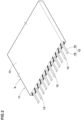
FIG.2 ]
An enlarged perspective view of the band ply inFIG.1 . - [
FIG.3 ]
An enlarged perspective view of the band cord inFIG.2 . - [
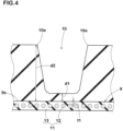
FIG. 4 ]
An enlarged cross-sectional view of a first circumferential groove and a band layer inFIG.1 . -
- 2
- Tread portion
- 2G
- Tread Rubber
- 9
- Band Layer
- 10
- First Circumferential Groove
- 10e
- Groove edge
- 12
- Band Cord
- 13
- Topping Rubber
- 16
- First Filament
- 17
- second Filament
- An embodiment of the present invention will be described below with reference to the drawings.
-
FIG.1 shows a meridian cross-sectional view of a pneumatic tire (hereinafter sometimes simply referred to as "tire") 1 in the present embodiment. -
FIG. 1 is a transverse cross-sectional view of the tire 1 under its normal state, including the rotational axis. - As shown in
FIG. 1 , the tire 1 in the present embodiment is a pneumatic tire for passenger cars. The present invention is however, not limited to such embodiment, and may be applied to tires for heavy loads and tires for motorcycles. - The "normal state" means, in the case of a tire for which various standards have been established, that the tire is mounted on a regular rim and inflated to a regular internal pressure but loaded with no load. In the case of a tire for which various standards have not been established, the normal state means a standard usage state according to the purpose of use of the tire, which is a state in which the tire is not mounted on the vehicle and no load is applied.
- The "regular rim" is a rim defined for each tire in a standard system that includes standards on which the tire is based, for example, "Standard Rim" in JATMA, "Design Rim" in TRA, and "Measuring Rim" in ETRTO.
- The "regular internal pressure" is air pressure specified for each tire by each standard in the standard system including the standards on which the tire is based, and is "maximum air pressure" in JATMA, the maximum value described in the table "TIRE LOAD LIMITS AT VARIOUS COLD INFLATION PRESSURES" in TRA and "INFLATION PRESSURE" in ETRTO.
- In this specification, unless otherwise noted, the dimensions of each part of the tire are the values measured under the normal state.
- In the case of a component inside the tire that cannot be measured while maintaining its normal state, its dimensions shall be measured while maintaining its shape under the normal state.
- Further, in this specification, unless otherwise noted, the composition of each part of the tire means the composition of the material taken out from a new and unused tire.
- As the taking-out method at that time, a method that does not change the composition as much as possible is appropriately adopted.
- The tire 1 in the present embodiment has a
carcass 6. Thecarcass 6 is composed of, for example, onecarcass ply 6A. Thecarcass ply 6A comprises a plurality of carcass cords, and topping rubber covering them. The carcass cords are arranged, for example, at an angle of 75 to 90 degrees with respect to the tire circumferential direction. - Incidentally, "75 to 90 degrees" means "not less than 75 degrees and not more than 90 degrees", and the same applies hereinafter in the present specification.
- As the carcass cords, preferably used are organic fiber cords such as nylon, polyester or rayon, and the like.
- The carcass ply 6A has a
main body portion 6a and a foldedportion 6b. - The
main body portion 6a extends from onebead portion 4 to theother bead portion 4 through onesidewall portion 3, atread portion 2 and theother sidewall portion 3. - The folded
portion 6b continues from themain body portion 6a, and is folded around abead core 5 from the inside to the outside in the tire axial direction so as to extend outward in the tire radial direction. - The
tread portion 2 of the present embodiment is provided with abelt layer 8. - The
belt layer 8 comprises, for example, two belt plies 8A and 8B. For example, each of the belt plies 8A and 8B comprises a plurality of belt cords arranged obliquely with respect to the tire circumferential direction, and a topping rubber covering them. - It is preferable that each belt cord is inclined at an angle of 10 to 45 degrees with respect to the tire circumferential direction.
- The
tread portion 2 comprises atread rubber 2G forming a ground contacting surface, and aband layer 9 disposed radially inside thetread rubber 2G. - The
tread rubber 2G is provided with at least one firstcircumferential groove 10 extending continuously in the tire circumferential direction in the ground contacting surface. Thetread rubber 2G of the present embodiment is provided with three firstcircumferential grooves 10. - The groove width of the first
circumferential groove 10 is, for example, 3 to 15 mm. - The depth of the first
circumferential groove 10 is, for example, 5 to 10 mm. - However, the groove width and groove depth of the first
circumferential groove 10 are not particularly limited as long as a certain degree of drainage can be expected during wet running. - Further, the
tread rubber 2G may be provided with a second circumferential groove different from the above-described firstcircumferential groove 10. - In
FIG.2 , an enlarged perspective view of theband layer 9 is shown. - The
band layer 9 is composed of, for example, oneband ply 11. The band ply 11 comprisesband cords 12 arranged substantially parallel to the tire circumferential direction, and a toppingrubber 13 covering theband cords 12. - For example, the
band layer 9 may be a plurality of superimposed band plies 11, or a plurality of band plies 11 arranged in the tire axial direction apart from each other. In the present embodiment, the band ply 11 is configured as a so-called jointless band in which, for example, a single band cord is wound in the tire circumferential direction. - In another embodiment, the band ply 11 may include a plurality of
band cords 12 arranged substantially parallel to the tire circumferential direction. - The expression "the
band cord 12 extends substantially parallel to the tire circumferential direction" includes at least such a mode that theband cord 12 extends at an angle of 5 degrees or less with respect to the tire circumferential direction. -
FIG.3 shows an enlarged perspective view of theband cord 12. - As shown in
FIG.3 , theband cord 12 is a hybrid cord in which afirst filament 16 and asecond filament 17 which has a smaller elastic modulus than thefirst filament 16 are twisted together. Thefirst filament 16 and thesecond filament 17 are made of organic fibers, and materials which have been conventionally used as materials for tire cords such as nylon, aramid and PET, are employed. Thereby, a known hybrid cord is appropriately employed for theband cord 12 of the present embodiment. - In
FIG.4 , there is shown an enlarged view of the firstcircumferential groove 10 and theband layer 9. InFIG.4 , the belt layer 8 (shown inFIG.1 ) disposed radially inside theband layer 9 is omitted. inFIG.4 , although the cross section of theband cord 12 is simplified and indicated by a circle, it goes without saying that theband cord 12 has the above-described configuration. - According to the present invention, as shown in
FIG. 4 , in a region radially inside the firstcircumferential groove 10, the maximum thickness t1 of the toppingrubber 13 on the radially outside of theband cord 12 is not more than 1.0 mm. Further, the minimum distance d1 from the groove bottom of the firstcircumferential groove 10 to the radially outer surface 9s of theband layer 9 is not more than 2.0 mm. Furthermore, the distance d2 in the tire normal direction from agroove edge 10e of the firstcircumferential groove 10 to the radially outer surface 9s of theband layer 9 is not more than 15.0 mm. - The outer surface 9s of the
band layer 9 means the outer surface of the toppingrubber 13 covering theband cord 12. - The tire normal direction means a direction normal to the ground contacting surface of the
tread portion 2. - In this specification, the ground contacting surface of the
tread portion 2 means a surface contacting with a plane when the tire 1 under the normal state is contacted with the plane at a camber angle of 0 degrees under the normal load. Further, the groove edge means the boundary between the opening area of the groove and the ground contacting surface. The ground contacting surface and the groove edge can be imaged by a known method such as CT imaging. - In the case of a pneumatic tire for which various standards have been established, the "normal load" is the load defined for each tire by each standard in the standard system including the standards on which that the tire is based, and is "maximum load capacity" in JATMA, the maximum value described in the table "TIRE LOAD LIMITS AT VARIOUS COLD INFLATION PRESSURES" in TRA, and "LOAD CAPACITY" in ETRTO.
- In the case of a tire for which various standards have not been established, the "normal load" refers to the load acting on one tire when the tire is in the standard mounting state.
- The "standard mounting state" refers to a state in which the tire is mounted on a standard vehicle according to the purpose of use of the tire, and the vehicle is standing still on a flat road surface in a drivable state.
- By employing the above configurations, the tire 1 of the present invention can improve steering stability during high-speed running while maintaining good ride comfort.
- As the reason therefor, it is presumed to be the following mechanism.
- In general, the
band layer 9 greatly influences the degree of vibration absorption of thetread portion 2 and the degree of outer diameter increase of thetread portion 2. - In other words, the
band layer 9 has a great influence on ride comfort during normal running and steering stability during high-speed running. - In the present invention, a hybrid cord is used for the
band cord 12 of theband layer 9. - Thereby, during normal running in which the outer diameter increase of the
tread portion 2 is small, the second filament 17 (shown inFIG.3 , the same applies hereinafter) having a lower elastic modulus becomes dominant, and good riding comfort is maintained. - During high-speed running, the first filament 16 (shown in
FIG.3 , the same applies hereinafter) having a higher elastic modulus, suppresses the outer diameter increase of thetread portion 2, and excellent steering stability is exhibited. - The developers have found, as a result of intensive research, that it is possible to further improve the steering stability by specifying the thickness of the rubber around the
band layer 9, and have completed the present invention. - In the present invention, as described above, the thickness t1 is defined as 1.0 mm or less, the distance d1 is defined as 2.0 mm or less, and the distance d2 is defined as 15.0 mm or less. Thereby, the thickness of the rubber on the radially outside of the
band cords 12 included in theband layer 9, can be set smaller, and the influence of the centrifugal force acting on thetread portion 2 during high-speed running can be reduced. - Therefore, the increase of the outer diameter of the
tread portion 2 is suppressed, the tread profile can be maintained even during high-speed running, and the ground contact of thetread portion 2 is improved. - It is believed that, by the mechanism described above, the present invention can improve steering stability during high-speed running while maintaining good ride comfort.
- More detailed configurations of the present embodiment will be described below.
- εach configuration described below represents a specific aspect of the present embodiment.
- Therefore, it goes without saying that the present invention can exhibit the above effects, even if it does not have the configurations described below.
- Further, even if any one of the configurations described below is applied alone to the tire of the present invention having the features described above, an improvement in performance according to each configuration can be expected. Furthermore, when some of the configurations described below are applied in combination, it is possible to expect a combined improvement in performance according to the respective configurations.
- As shown in
FIG.3 , theband cord 12 of the present embodiment is formed as a multi-twisted structure by twisting together afirst yarn 18 formed by twistingfirst filaments 16 together, and asecond yarn 19 formed by twistingsecond filaments 17 together. However, theband cord 12 is not limited to such a mode, and may have a single twist structure including thefirst filaments 16 and thesecond filaments 17. - The difference in elastic modulus between the
first filament 16 and thesecond filament 17 is determined, for example, by tensile strength specified in JIS L1017. - The conditions for measuring the tensile strength are not particularly limited as long as the tensile strength of the
first filament 16 and the tensile strength of thesecond filament 17 are measured under the same conditions. - The total fineness of one
band cord 12 is, for example, not more than 4400 dtex, preferably 2000 to 4000 dtex, more preferably 2500 to 3500 dtex. -
Such band cord 12 is helpful for improving riding comfort and steering stability in a well-balanced manner. - The stress σ1 of the
band cord 12 when elongated by 3% is, for example, not more than 0.030 (N/tex). The stress σ1 is preferably not less than 0.005 (N/tex), more preferably not less than 0.010 (N/tex), and preferably not more than 0.025 (N/tex), more preferably not more than 0.020 (N/tex). -
such band cord 12 can exhibit excellent ride comfort, while maintaining the durability of thetread portion 2. - The stress σ2 of the
band cord 12 when elongated by 5% is, for example, not less than 0.04 (N/tex). The stress σ2 is preferably not less than 0.043 (N/tex), more preferably not less than 0.045 (N/tex), and preferably not more than 0.06 (N/tex),more preferably not more than 0.055 (N/tex). -
such band cord 12 is helpful for improving ride comfort and steering stability at high speeds in a well-balanced manner. - The ratio σ1/σ2 (%) between the stress σ1 and the stress θ2 is preferably not less than 25%, more preferably not less than 29%, and preferably not more than 50%, more preferably not more than 43%.
- The stress σ1 and the stress σ2 described above are measured, for example, by the method of measuring load under constant extension specified in JIS L1017.
- As shown in
FIG.1 , thetread rubber 2G is provided with a plurality of firstcircumferential grooves 10. Further, thetread rubber 2G is provided with a plurality of lateral grooves (not shown) extending in the tire axial direction in the ground contacting surface. - From the viewpoint of achieving both ride comfort and steering stability, the sea ratio of the ground contacting surface of the
tread portion 2 is preferably not less than 15%, more preferably not less than 20%, and preferably not more than 50%, more preferably not more than 40%, still more preferably not more than 30%. - Incidentally, the sea ratio is the ratio of the sum of the opening areas of all the grooves to the total area of the virtual ground contacting surface in such a state that all the grooves in the ground contacting surface of the
tread rubber 2G are filled up. - It is preferable that the ratio σ1/σ2 (%) of the stress σ1 (N/tex) when the
band cord 12 is stretched by 3% to the stress σ2 (N/tex) when theband cord 12 is stretched by 5% is larger than the sea ratio (%) of the ground contacting surface of the tread portion. - specifically, the ratio σ1/σ2 (%) is preferably not less than 1.50 times, more preferably not less than 1.90 times, and preferably not more than 3.00 times, more preferably not more than 2.86 times the sea ratio (%).
- Thereby, the ratio σ1/σ2 is optimized, and excellent steering stability is exhibited both during low-to-medium speed running and high speed running.
- The
tread rubber 2G includes, for example, a rubber compound having a complex elastic modulus E*1 of 10 to 20 (MPa) at 30 degrees C. - The complex elastic modulus E*1 is more preferably 12 to 18 (MPa).
- On the other hand, in the case of a tire in which riding comfort is important, the complex elastic modulus E*1 at 30 degrees C. of the
tread rubber 2G may be not more than 10 (MPa). - The complex elastic modulus E*1 is a value measured using a "viscoelastic spectrometer" manufactured by Iwamoto Seisakusho Co., Ltd. under the following conditions in accordance with JIS-K6394.
- As a test sample for measurement, there is used, for example, a rubber piece obtained from the
tread rubber 2G so that the long side is in the tire circumferential direction, the short side is in the tire axial direction, and the thickness is in the tire radial direction.
for example, the size of the rubber piece is 20 mm long side x 4 mm short side x 1 mm thick. - Initial Strain: 10%
- Amplitude: +/-1%
- Frequency: 8 Hz
- Deformation mode: tensile
- Measurement temperature: 30 degrees C
- The developers have found, as a result of various experiments, that specifying the complex elastic modulus E*1 of the
tread rubber 2G according to the sea ratio, contributes to both ride comfort and steering stability. specifically, the product of the complex elastic modulus E*1 (MPa) and the sea ratio (%) is preferably not less than 3.0 (MPa), more preferably not less than 4.3 (MPa), and preferably not more than 9.0 (MPa), more preferably not more than 7.5 (MPa). - Thereby, the amount of deformation of the
tread portion 2 during running is optimized, and ride comfort and steering stability can be improved in a well-balanced manner. - Further, the product σ2·E*1 of the stress σ2 (N/tex) at 5% elongation of the band cord and the complex elastic modulus E*1 (MPa) is preferably not less than 0.45 (N· MPa/tex), more preferably not less than 0.60 (N·MPa/tex), and preferably not more than 1.05 (N·MPa/tex), more preferably not more than 0.90 (N·MPa/tex).
- Thereby, the amount of deformation of the
tread portion 2 and theband layer 9 during high-speed running is optimized, and ride comfort and steering stability are improved in a well-balanced manner. - As shown in
FIG.4 , the thickness t1 is preferably not less than 0.05 mm, more preferably not less than 0.10 mm, and preferably not more than 0.50 mm, more preferably not more than 0.30 mm. Thereby, the above-mentioned effect can be exhibited while ensuring the durability of the band layer. - The distance d1 is preferably not less than 0.5 mm, more preferably not less than 1.0 mm, and preferably not more than 1.8 mm, more preferably not more than 1.5 mm. Thereby, at the groove bottom of the first
circumferential groove 10, the thickness of the rubber is optimized, and the above-described effects are exhibited more reliably. - The distance d2 is preferably not less than 5.0 mm, more preferably not less than 7.0 mm, and preferably not more than 12.0 mm, more preferably not more than 10.0 mm. Thereby, the thickness of the
tread rubber 2G is optimized. - The developers have found that the above-described effect can be further improved by specifying the stress σ1 of the
band cord 12 when elongated by 3% and the distance d2 in association with each other. - specifically, the product σ1·d2 of the stress σ1 (N/tex) and the distance d2 (mm) is preferably 0.05 to 0.40 (N·mm/tex), more preferably 0.08 to 0.18.
- Thereby, the amount of deformation of the
tread portion 2 during medium to low speed running is optimized, and ride comfort can be further improved. - Similarly, it was found that the steering stability is further improved by specifying the stress σ2 of the
band cord 12 when elongated by 5% and the distance d2 in association with each other. - specifically, the product σ2·d2 of the stress σ2 (N/tex) and the distance d2 (mm) is preferably 0.30 to 0.60 (N·mm/tex), more preferably, 0.35 to 0.50.
- Thereby, the amount of deformation of the
tread portion 2 during high-speed running is optimized, and steering stability during high-speed running is further improved. - A ratio t1/d1 (%) between the thickness t1 and the distance d1 is preferably not less than 5%, more preferably not less than 6.7%, and preferably not more than 46.2%, more preferably not more than 30.8%.
- Further, it is preferable that the ratio t1/d1 (%) between the thickness t1 and the distance d1 is smaller than the sea ratio (%). Specifically, the ratio t1/d1 (%) is preferably not less than 0.15 times, more preferably not less than 0.26 times, and preferably not more than 0.77 times, more preferably not more than 0.67 times the sea ratio (%). Thereby, the thickness t1 is optimized, and ride comfort is improved while maintaining the durability of the
band layer 9. - In addition, it was found that the distance d1 and the complex elastic modulus E*1 have a large effect on ride comfort and steering stability, and it is preferable for improving these performances in a well-balanced manner, to define the distance d1 and the complex elastic modulus E*1 in association with each other.
- specifically, the product of the distance d1 (mm) and the complex elastic modulus E*1 (MPa) is preferably not less than 12.0 (MPa·mm), more preferably not less than 15.0 (MPa·mm), and preferably not more than 30.0 (MPa·mm), more preferably not more than 22.5 (mPa·mm).
- Thereby, deformation of the rubber near the groove bottom of the first
circumferential groove 10 is optimized, and steering stability during high-speed running can be improved while maintaining good ride comfort. - As shown in
FIG.1 , thetread rubber 2G of the present embodiment is provided with three firstcircumferential grooves 10, and the above-described configuration is satisfied by at least one of the firstcircumferential grooves 10. - In a more desirable mode, all of the plurality of first
circumferential grooves 10 disposed in thetread rubber 2G satisfy the above-described configuration. Thereby, the above-described effects can be reliably exhibited. - while detailed description has been made of an especially preferable embodiment of the present invention, the present invention can be embodied in various modes without being limited to the illustrated embodiment.
- Pneumatic tires of size 215/60R16 satisfying the requirements of the present invention were experimentally manufactured based on the specifications shown in Tables 1-4. As Comparative Example 1, a pneumatic tire was experimentally manufactured, wherein a band cord was a hybrid cord, and a thickness t1, a distance d1 and a distance d2 did not satisfy the requirements of the present invention.
- As Comparative Example 2, a pneumatic tire was experimentally manufactured, wherein a band cord is made of nylon material only, and a thickness t1, a distance d1 and a distance d2 did not satisfy the requirements of the present invention.
- εxcept for the specifications shown in Tables 1-4, the tires of Comparative Examples 1 and 2 had configurations substantially the same as those of the tires of Embodiments.
- εach test tire was tested for ride comfort and steering stability at high speeds.
- The common specifications of the test tires and test methods are as follows.
- Mounted rim: 16 x 6.5J
- Internal pressure: 210 kPa
- Test vehicle displacement: 2000cc
- Drive system: FF
- Test tire mounted position: All wheels
- Ride comfort when the test vehicle was run on a general road was evaluated by the following method.
- εach of 20 test drivers conducted a test drive, and scored the ride comfort on a scale of 1 to 10 points (higher number is better), and the total score of the 20 test drivers was calculated.
- The results are indicated by a score based on the sum of the above-mentioned scoring result of Comparative Example 1 being 100, wherein the larger the value, the better the riding comfort.
- steering stability when the test vehicle was run at high speed, was evaluated by the following method.
- εach of the 20 test drivers conducted a test drive, and scored the steering stability on a scale of 1 to 10 points (higher number is better), and the total score of the 20 test drivers was calculated.
- The results are indicated by a score based on the sum of the above-mentioned scoring result of Comparative Example 1 being 100, wherein the larger the value, the better the steering stability during high-speed running.
- Comprehensive performance including the above-mentioned ride comfort and steering stability at high speeds, was evaluated. The results are the sum of the scores for ride comfort and steering stability during high-speed running, wherein the larger the number, the better the overall performance.
- The test results are shown in Tables 1-4.
[Table 1] Comparative example 2 Comparative example 1 Embodiment 1 Embodiment 2Embodiment 3Embodiment 4Thickness t1 (mm) 1.2 1.2 0.1 0.4 0.6 0.8 Distance d1 (mm) 2.2 2.2 1.3 1.3 1.3 1.3 Distance d2(mm) 17.0 17.0 8.0 8.0 8.0 8.0 Total fineness of band cord (dtex) 3000 4400 3000 3000 3000 3000 Stress σ1 at 3% elongation of band cord (N/tex) 0.015 0.01 0.015 0.015 0.015 0.015 Stress σ2 at 5% elongation of band cord (N/tex) 0.05 0.02 0.05 0.05 0.05 0.05 Ratio σ1/σ2 (%) 30 50 30 30 30 30 Sea ratio of tread portion (%) 15 15 15 15 15 15 (σ1/σ2)/sea ratio 2.00 3.33 2.00 2.00 2.00 2.00 Complex elastic modulus E*1 of tread rubber(MPa) 15 15 15 15 15 15 E*1 x Sea ratio(MPa) 4.5 7.5 4.5 4.5 4.5 4.5 Product σ1·d2(N·mm/tex) 0.26 0.17 0.12 0.12 0.12 0.12 Product σ2·d2(N·mm/tex) 0.85 0.34 0.40 0.40 0.40 0.40 Ratio t1/d1 (%) 54.5 54.5 7.7 30.8 46.2 61.5 (t1/d1)/Sea ratio 3.6 3.6 0.51 2.1 3.1 4.1 Product d1·E*1 (MPa·mm) 33.0 33.0 19.5 19.5 19.5 19.5 Product σ2·E*1 (N·MPa/tex) 0.75 0.30 0.75 0.75 0.75 0.75 Ride comfort (score) 100 96 107 102 101 101 Steering stability at high speed (score) 100 91 109 109 107 105 Comprehensive performance 200 187 216 211 208 206 [Table 2] Embodiment 5Embodiment 6Embodiment 7 Embodiment 8Embodiment 9Embodiment 10Thickness t1 (mm) 1.0 0.1 0.1 0.1 0.1 0.1 Distance d1 (mm) 1.3 0.8 1.0 1.5 2.0 1.3 Distance d2(mm) 8.0 8.0 8.0 8.0 8.0 7.0 Total fineness of band cord (dtex) 3000 3000 3000 3000 3000 3000 Stress σ1 at 3% elongation of band cord (N/tex) 0.015 0.015 0.015 0.015 0.015 0.015 Stress σ2 at 5% elongation of band cord (N/tex) 0.05 0.05 0.05 0.05 0.05 0.05 Ratio σ1/σ2 (%) 30 30 30 30 30 30 Sea ratio of tread portion (%) 15 15 15 15 15 15 (σ1/σ2)/sea ratio 2.00 2.00 2.00 2.00 2.00 2.00 Complex elastic modulus E*1 of tread rubber(MPa) 15 15 15 15 15 15 E*1 x Sea ratio(MPa) 4.5 4.5 4.5 4.5 4.5 4.5 Product σ1·d2(N·mm/tex) 0.12 0.12 0.12 0.12 0.12 0.11 Product σ2·d2(N·mm/tex) 0.40 0.40 0.40 0.40 0.40 0.35 Ratio t1/d1 (%) 76.9 12.5 10.0 6.7 5.0 7.7 (t1/d1)/Sea ratio 5.1 0.83 0.67 0.44 0.33 0.51 Product d1·E*1 (MPa·mm) 19.5 12.0 15.0 22.5 30.0 19.5 Product σ2.E*1 (N·MPa/tex) 0.75 0.75 0.75 0.75 0.75 0.75 Ride comfort (score) 100 100 101 102 100 100 Steering stability at high speed (score) 105 105 107 108 105 109 Comprehensive performance 205 205 208 210 205 209 [Table 3] Embodiment 11Embodiment 12Embodiment 13Embodiment 14 Embodiment 15 Embodiment 16Embodiment 17Thickness t1 (mm) 0.1 0.1 0.1 0.1 0.1 0.1 0.1 Distance d1 (mm) 1.3 1.3 1.3 1.3 1.3 1.3 1.3 Distance d2(mm) 10.0 12.0 15.0 8.0 8.0 8.0 8.0 Total fineness of band cord (dtex) 3000 3000 3000 2900 3500 4400 4500 Stress σ1 at 3% elongation of band cord (N/tex) 0.015 0.015 0.015 0.010 0.025 0.03 0.04 Stress σ2 at 5% elongation of band cord (N/tex) 0.05 0.05 0.05 0.035 0.06 0.07 0.08 Ratio σ1/σ2 (%) 30 30 30 29 42 43 50 Sea ratio of tread portion (%) 15 15 15 15 15 15 15 (σ1/σ2)/sea ratio 2.00 2.00 2.00 1.90 2.78 2.86 3.33 Complex elastic modulus E*1 of tread rubber(MPa) 15 15 15 15 15 15 15 E*1 x Sea ratio(MPa) 4.5 4.5 4.5 4.3 6.3 6.4 7.5 Product σ1·d2(N·mm/tex) 0.15 0.18 0.23 0.08 0.20 0.24 0.32 Product σ2·d2(N·mm/tex) 0.50 0.60 0.75 0.28 0.48 0.56 0.64 Ratio t1/d1 (%) 7.7 7.7 7.7 7.7 7.7 7.7 7.7 (t1/d1)/Sea ratio 0.51 0.51 0.51 0.51 0.51 0.51 0.51 Product d1·E*1 (MPa·mm) 19.5 19.5 19.5 19.5 19.5 19.5 19.5 Product σ2·E*1 (N·MPa/tex) 0.75 0.75 0.75 0.53 0.90 1.05 1.20 Ride comfort (score) 101 100 100 101 100 99 98 Steering stability at high speed (score) 107 104 103 104 109 111 114 Comprehensive performance 208 204 203 205 209 210 212 [Table 4] Embodiment 18Embodiment 19Embodiment 20 Embodiment 21 Embodiment 22 Embodiment 23 Embodiment 24 Thickness t1 (mm) 0.1 0.1 0.1 0.1 0.1 0.1 0.1 Distance d1 (mm) 1.3 1.3 1.3 1.3 1.3 1.3 1.3 Distance d2(mm) 8.0 8.0 8.0 8.0 8.0 8.0 8.0 Total fineness of band cord (dtex) 3000 3000 3000 3000 3000 3000 3000 Stress σ1 at 3% elongation of band cord (N/tex) 0.015 0.015 0.015 0.015 0.015 0.015 0.015 Stress σ2 at 5% elongation of band cord (N/tex) 0.05 0.05 0.05 0.05 0.05 0.05 0.05 Ratio σ1/σ2 (%) 30 30 30 30 30 30 30 Sea ratio of tread portion (%) 10 20 30 50 15 15 15 (σ1/σ2)/sea ratio 3.00 1.50 1.00 0.60 2.00 2.00 2.00 Complex elastic modulus E*1 of tread rubber(MPa) 15 15 15 15 9 12 20 E*1 x Sea ratio(MPa) 3.0 6.0 9.0 15.0 4.5 4.5 4.5 Product σ1·d2(N·mm/tex) 0.12 0.12 0.12 0.12 0.12 0.12 0.12 Product σ2·d2(N·mm/tex) 0.40 0.40 0.40 0.40 0.40 0.40 0.40 Ratio t1/d1 (%) 7.7 7.7 7.7 7.7 7.7 7.7 7.7 (t1/d1)/Sea ratio 0.77 0.38 0.26 0.15 0.51 0.51 0.51 Product d1·E*1 (MPa·mm) 19.5 19.5 19.5 19.5 11.7 15.6 26.0 Product σ2·E*1 (N·MPa/tex) 0.75 0.75 0.75 0.75 0.45 0.60 1.00 Ride comfort (score) 100 102 103 105 105 102 98 Steering stability at high speed (score) 112 109 105 104 104 105 112 Comprehensive performance 212 211 208 209 209 207 210 - In Tables 1 to 4, with respect to the ride comfort, when the score is higher than 96 of Comparative Example 2, it can be evaluated as "good ride comfort is maintained." Further, with respect to the steering stability during high-speed running, when the score is higher than 100 of Comparative Example 1, it can be evaluated as the steering stability is improved.
- As a result of the test, it was confirmed that the embodiment tires were improved in the steering stability at high speed while maintaining good ride comfort, and improved in the overall performance including the ride comfort and steering stability.
Claims (14)
- A pneumatic tire (1) having a tread portion (2), whereinthe tread portion (2) comprises a tread rubber (2G) forming a ground contacting surface, and a band layer (9) disposed radially inside the tread rubber (2G),the tread rubber (2G) is provided with a first circumferential groove (10) extending continuously in the tire circumferential direction in the ground contacting surface,the band layer (9) comprises band cords (12) arranged substantially parallel to the tire circumferential direction, and a topping rubber (13) covering the band cords (12), andthe band cords (12) are a hybrid cord in which a first filament (16) and a second filament (17) having an elastic modulus lower than that of the first filament (16) are twisted together,characterized in thatin a region radially inside the first circumferential groove (10), a maximum thickness t1 of the topping rubber (13) on the radially outer side of the band cord (12) is not more than 1.0 mm,a minimum distance d1 from the bottom of the first circumferential groove (10) to the radially outer surface (9s) of the band layer (9) is not more than 2.0 mm,a distance d2 in a tire normal direction from a groove edge (10e) of the first circumferential groove (10) to the radially outer surface (9s) of the band layer (9) is not more than 15.0 mm, anda sea ratio of the ground contacting surface of the tread portion (2) is 15% to 50%, wherein the sea ratio is the ratio of the sum of the opening areas of all the grooves to the total area of the virtual ground contacting surface in such a state that all the grooves in the ground contacting surface of the tread rubber are filled up.
- The pneumatic tire (1) according to claim 1, wherein the first filament (16) and the second filament (17) are made of organic fibers.
- The pneumatic tire (1) according to claim 1 or 2, wherein the band cord (12) has a total fineness of not more than 4400 dtex.
- The pneumatic tire according to any one of claims 1 to 3, wherein a stress σ1 of the band cord when elongated by 3% is not more than 0.03 N/tex, measured by the method of measuring load under constant extension specified in the Japanese Industrial Standard (JIS) L1017.
- The pneumatic tire (1) according to claim 4, wherein a product σ1·d2 of the stress σ1 (N/tex) and the distance d2 (mm) is 0.05 to 0.40 N*mm/tex.
- The pneumatic tire (1) according to any one of claims 1 to 5, wherein a stress σ2 of the band cord (12) when elongated by 5% is 0.04 to 0.06 N/tex, measured by the method of measuring load under constant extension specified in the Japanese Industrial Standard (JIS) L1017.
- The pneumatic tire (1) according to claim 6, wherein the product σ2·d2 of the stress σ2 (N/tex) and the distance d2 (mm) is 0.30 to 0.60 N*mm/tex.
- The pneumatic tire (1) according to claim 1, wherein a ratio t1/d1 (%) between the thickness t1 and the distance d1 is smaller than the shear ratio (%).
- The pneumatic tire (1) according to any one of claims 1 to 8, wherein the tread rubber (2G) includes a rubber compound having a complex elastic modulus E*1 of not more than 10 MPa, wherein the complex elastic modulus E*1 is measured at 30 degrees C in accordance with JIS-K6394 with an initial strain of 10%, with an amplitude of +/-1% and a frequency of 8 Hz.
- The pneumatic according to claim 9, wherein the product d1·E*1 of the distance d1 (mm) and the complex elastic modulus E*1 (MPa) is 5.0 to 30.0 MPa * mm.
- The pneumatic tire (1) according to claim 9 or 10, wherein the product σ2·E*1 of the stress σ2 (N/tex) at 5% elongation of the band cord (12) and the complex elastic modulus E*1 (MPa) is 0.40 to 1.60 N * MPa/ tex.
- The pneumatic tire (1) according to any one of claims 9 to 11, wherein the product of the complex elastic modulus E*1 (MPa) and the sea ratio (%) of the ground contacting surface of the tread portion (2) is not more than 5.0 MPa.
- The pneumatic tire (1) according to any one of claims 1 to 12, wherein a ratio σ1/σ2 (%) of the stress σ1 (N/tex) at 3% elongation of the band cord (12) to the stress σ2 (N/tex) at 5% elongation of the band cord (12) is greater than the sea ratio (%) of the ground contacting surface of the tread portion (2).
- The pneumatic tire (1) according to any one of claims 1 to 13, wherein the thickness t1 is 0.05 to 0.30 mm, the distance d1 is 0.5 to 1.5 mm, and the distance d2 is 5.0 to 12.0 mm.
Applications Claiming Priority (2)
| Application Number | Priority Date | Filing Date | Title |
|---|---|---|---|
| JP2021072796 | 2021-04-22 | ||
| PCT/JP2022/010235 WO2022224610A1 (en) | 2021-04-22 | 2022-03-09 | Pneumatic tire |
Publications (3)
| Publication Number | Publication Date |
|---|---|
| EP4173844A1 EP4173844A1 (en) | 2023-05-03 |
| EP4173844A4 EP4173844A4 (en) | 2024-01-17 |
| EP4173844B1 true EP4173844B1 (en) | 2025-01-15 |
Family
ID=83722833
Family Applications (1)
| Application Number | Title | Priority Date | Filing Date |
|---|---|---|---|
| EP22791391.0A Active EP4173844B1 (en) | 2021-04-22 | 2022-03-09 | Pneumatic tire |
Country Status (5)
| Country | Link |
|---|---|
| US (1) | US12330451B2 (en) |
| EP (1) | EP4173844B1 (en) |
| JP (1) | JPWO2022224610A1 (en) |
| CN (1) | CN116323253B (en) |
| WO (1) | WO2022224610A1 (en) |
Families Citing this family (1)
| Publication number | Priority date | Publication date | Assignee | Title |
|---|---|---|---|---|
| FR3159556A1 (en) * | 2024-02-23 | 2025-08-29 | Compagnie Generale Des Etablissements Michelin | Tire with a complex wear-resistant tread |
Citations (22)
| Publication number | Priority date | Publication date | Assignee | Title |
|---|---|---|---|---|
| JPH04314604A (en) | 1991-04-11 | 1992-11-05 | Yokohama Rubber Co Ltd:The | Pneumatic radial tire for passenger car |
| JPH06255312A (en) | 1993-03-09 | 1994-09-13 | Yokohama Rubber Co Ltd:The | Pneumatic radial tire |
| WO1999052720A1 (en) | 1998-08-26 | 1999-10-21 | The Goodyear Tire & Rubber Company | An on/off-road tread |
| JP2001347809A (en) | 2000-06-05 | 2001-12-18 | Sumitomo Rubber Ind Ltd | Pneumatic tire |
| JP2005263175A (en) | 2004-03-22 | 2005-09-29 | Sumitomo Rubber Ind Ltd | Pneumatic tire |
| EP1800904A1 (en) | 2005-12-21 | 2007-06-27 | Sumtiomo Rubber Industries Ltd | Pneumatic tire |
| US20080271830A1 (en) | 2007-05-02 | 2008-11-06 | Sumitomo Rubber Industries, Ltd. | Tire for motorcycle |
| US7484545B2 (en) | 2005-12-20 | 2009-02-03 | The Goodyear Tire & Rubber Co. | Radial tire for aircraft with specified merged cords |
| JP2009052158A (en) | 2007-08-24 | 2009-03-12 | Bridgestone Corp | Composite of cord and rubber and pneumatic tire using the same |
| JP2009137403A (en) | 2007-12-05 | 2009-06-25 | Sumitomo Rubber Ind Ltd | Pneumatic radial-ply tire |
| EP2239153A1 (en) | 2009-04-06 | 2010-10-13 | Sumitomo Rubber Industries, Ltd. | Pneumatic tire |
| EP2698262A1 (en) | 2011-04-11 | 2014-02-19 | Sumitomo Rubber Industries, Ltd. | Pneumatic tire |
| EP2781373A1 (en) | 2013-03-19 | 2014-09-24 | Sumitomo Rubber Industries, Ltd. | Pneumatic tire |
| EP3012118A1 (en) | 2013-07-05 | 2016-04-27 | Sumitomo Rubber Industries, Ltd. | Pneumatic tire |
| CN107444025A (en) | 2017-08-09 | 2017-12-08 | 安徽佳通乘用子午线轮胎有限公司 | Tire with plshy bone open pattern block |
| EP3287299A1 (en) | 2016-08-26 | 2018-02-28 | Continental Reifen Deutschland GmbH | Stability beam support for elastomeric products, in particular for a carcass bearing of a pneumatic tyre for a vehicle, comprising a hybrid cord |
| EP3351406A2 (en) | 2017-01-24 | 2018-07-25 | Sumitomo Rubber Industries, Ltd. | Pneumatic tire |
| EP3287300B1 (en) | 2016-08-26 | 2019-06-19 | Continental Reifen Deutschland GmbH | Stability beam support for elastomeric products, in particular for a carcass bearing of a pneumatic tyre for a vehicle, comprising a hybrid cord |
| EP3718787A1 (en) | 2019-04-03 | 2020-10-07 | Sumitomo Rubber Industries, Ltd. | Tire |
| US20200384809A1 (en) | 2017-12-13 | 2020-12-10 | Continental Reifen Deutschland Gmbh | Reinforcement Layer and Pneumatic Vehicle Tire |
| JP6848319B2 (en) | 2016-10-06 | 2021-03-24 | 横浜ゴム株式会社 | Pneumatic tires |
| WO2022148921A1 (en) | 2021-01-07 | 2022-07-14 | Compagnie Generale Des Etablissements Michelin | Tyre comprising a bracing ply having a hydrophobic weft and a reduced crown thickness |
Family Cites Families (15)
| Publication number | Priority date | Publication date | Assignee | Title |
|---|---|---|---|---|
| DE69403315T2 (en) * | 1993-12-28 | 1997-08-28 | Sumitomo Rubber Ind | Radial pneumatic tire |
| JP2966748B2 (en) * | 1994-03-08 | 1999-10-25 | 住友ゴム工業株式会社 | Pneumatic tire |
| JPH08142609A (en) * | 1994-11-18 | 1996-06-04 | Ohtsu Tire & Rubber Co Ltd :The | Pneumatic tire |
| US6082423A (en) * | 1997-06-09 | 2000-07-04 | The Goodyear Tire & Rubber Company | Low cost light weight radial tire |
| US6601378B1 (en) * | 1999-09-08 | 2003-08-05 | Honeywell International Inc. | Hybrid cabled cord and a method to make it |
| EP2581239A1 (en) * | 2006-01-20 | 2013-04-17 | The Yokohama Rubber Co., Ltd. | Pneumatic tire |
| JP2011218980A (en) * | 2010-04-09 | 2011-11-04 | Toyo Tire & Rubber Co Ltd | Pneumatic radial tire |
| JP5206754B2 (en) * | 2010-09-09 | 2013-06-12 | 横浜ゴム株式会社 | Pneumatic tire |
| JP5602037B2 (en) * | 2011-01-31 | 2014-10-08 | 住友ゴム工業株式会社 | Method for predicting cornering performance of automotive tires |
| JP5395882B2 (en) * | 2011-12-01 | 2014-01-22 | 住友ゴム工業株式会社 | Pneumatic tire |
| JP5650690B2 (en) * | 2012-06-12 | 2015-01-07 | 住友ゴム工業株式会社 | Rubber composition for tread and pneumatic tire |
| US20150273954A1 (en) * | 2014-03-26 | 2015-10-01 | American Engineering Group LLC | Zero-pressure tire |
| JP6661949B2 (en) * | 2015-10-06 | 2020-03-11 | 横浜ゴム株式会社 | Pneumatic tire |
| JP2018154075A (en) | 2017-03-21 | 2018-10-04 | 住友ゴム工業株式会社 | Production method of pneumatic tire |
| JP6863503B1 (en) * | 2020-04-24 | 2021-04-21 | 住友ゴム工業株式会社 | tire |
-
2022
- 2022-03-09 JP JP2023516324A patent/JPWO2022224610A1/ja active Pending
- 2022-03-09 CN CN202280006824.2A patent/CN116323253B/en active Active
- 2022-03-09 EP EP22791391.0A patent/EP4173844B1/en active Active
- 2022-03-09 US US18/286,444 patent/US12330451B2/en active Active
- 2022-03-09 WO PCT/JP2022/010235 patent/WO2022224610A1/en not_active Ceased
Patent Citations (22)
| Publication number | Priority date | Publication date | Assignee | Title |
|---|---|---|---|---|
| JPH04314604A (en) | 1991-04-11 | 1992-11-05 | Yokohama Rubber Co Ltd:The | Pneumatic radial tire for passenger car |
| JPH06255312A (en) | 1993-03-09 | 1994-09-13 | Yokohama Rubber Co Ltd:The | Pneumatic radial tire |
| WO1999052720A1 (en) | 1998-08-26 | 1999-10-21 | The Goodyear Tire & Rubber Company | An on/off-road tread |
| JP2001347809A (en) | 2000-06-05 | 2001-12-18 | Sumitomo Rubber Ind Ltd | Pneumatic tire |
| JP2005263175A (en) | 2004-03-22 | 2005-09-29 | Sumitomo Rubber Ind Ltd | Pneumatic tire |
| US7484545B2 (en) | 2005-12-20 | 2009-02-03 | The Goodyear Tire & Rubber Co. | Radial tire for aircraft with specified merged cords |
| EP1800904A1 (en) | 2005-12-21 | 2007-06-27 | Sumtiomo Rubber Industries Ltd | Pneumatic tire |
| US20080271830A1 (en) | 2007-05-02 | 2008-11-06 | Sumitomo Rubber Industries, Ltd. | Tire for motorcycle |
| JP2009052158A (en) | 2007-08-24 | 2009-03-12 | Bridgestone Corp | Composite of cord and rubber and pneumatic tire using the same |
| JP2009137403A (en) | 2007-12-05 | 2009-06-25 | Sumitomo Rubber Ind Ltd | Pneumatic radial-ply tire |
| EP2239153A1 (en) | 2009-04-06 | 2010-10-13 | Sumitomo Rubber Industries, Ltd. | Pneumatic tire |
| EP2698262A1 (en) | 2011-04-11 | 2014-02-19 | Sumitomo Rubber Industries, Ltd. | Pneumatic tire |
| EP2781373A1 (en) | 2013-03-19 | 2014-09-24 | Sumitomo Rubber Industries, Ltd. | Pneumatic tire |
| EP3012118A1 (en) | 2013-07-05 | 2016-04-27 | Sumitomo Rubber Industries, Ltd. | Pneumatic tire |
| EP3287299A1 (en) | 2016-08-26 | 2018-02-28 | Continental Reifen Deutschland GmbH | Stability beam support for elastomeric products, in particular for a carcass bearing of a pneumatic tyre for a vehicle, comprising a hybrid cord |
| EP3287300B1 (en) | 2016-08-26 | 2019-06-19 | Continental Reifen Deutschland GmbH | Stability beam support for elastomeric products, in particular for a carcass bearing of a pneumatic tyre for a vehicle, comprising a hybrid cord |
| JP6848319B2 (en) | 2016-10-06 | 2021-03-24 | 横浜ゴム株式会社 | Pneumatic tires |
| EP3351406A2 (en) | 2017-01-24 | 2018-07-25 | Sumitomo Rubber Industries, Ltd. | Pneumatic tire |
| CN107444025A (en) | 2017-08-09 | 2017-12-08 | 安徽佳通乘用子午线轮胎有限公司 | Tire with plshy bone open pattern block |
| US20200384809A1 (en) | 2017-12-13 | 2020-12-10 | Continental Reifen Deutschland Gmbh | Reinforcement Layer and Pneumatic Vehicle Tire |
| EP3718787A1 (en) | 2019-04-03 | 2020-10-07 | Sumitomo Rubber Industries, Ltd. | Tire |
| WO2022148921A1 (en) | 2021-01-07 | 2022-07-14 | Compagnie Generale Des Etablissements Michelin | Tyre comprising a bracing ply having a hydrophobic weft and a reduced crown thickness |
Non-Patent Citations (30)
| Title |
|---|
| ANONYMOUS: "# Entretien pneus - Profondeur de gomme - Lâimportance de la profondeur des sculptures", CONTINENTAL (ACCESSED VIA THE WAYBACK MACHINE), 12 July 2025 (2025-07-12), XP093331820, Retrieved from the Internet <URL:https://web.archive.org/web/20250712004346/https://www.continental-tires.com/fr/fr/tire-knowledge/tread-depth/> |
| ANONYMOUS: "Comment vérifier la profondeur de la bande de roulement des pneus : Le test du sou noir", BRIDGESTONE, 1 April 2021 (2021-04-01), XP093331781, Retrieved from the Internet <URL:https://tires.bridgestone.com/fr-ca/learn/tire-maintenance/how-to-check-your-tire-tread-penny-test#> |
| ANONYMOUS: "MICHELIN INTRODUCES PILOT SPORT 4 S TO NORTH AMERICAN MARKET AT NAIAS", MICHELIN, 10 January 2017 (2017-01-10), XP093331828, Retrieved from the Internet <URL:https://michelinmedia.com/site/user/files/1/Michelin-Pilot-Sport-4-S-Final-Press-Release_2.pdf> |
| ANONYMOUS: "PNEU : NOS TESTS DE GOMMES LARGES SOUS LA PLUIE", AUTOPLUS, 14 January 2017 (2017-01-14), XP093331785, Retrieved from the Internet <URL:https://www.autoplus.fr/pratique/pneus/pneu-nos-tests-de-gommes-larges-sous-la-pluie-366320.html> |
| ANONYMOUS: "Pneus / ESSAI -Michelin PS4S : Le pneu sport aux deux visages", MONITEURAUTOMOBILE.BE, 27 January 2017 (2017-01-27), XP093331831, Retrieved from the Internet <URL:https://www.moniteurautomobile.be/actu-auto/pneus/essai-michelin-ps4s-2017.html> |
| ANONYMOUS: "Profondeur de gomme - Comment vérifier la profondeur des sculptures de vos pneus", UNIROYAL, 1 January 2023 (2023-01-01), XP093331823, Retrieved from the Internet <URL:https://www.uniroyal-tyres.com/be/fr/car/service-knowledge/how-to-check-your-tyres-tread-depth/> |
| ANONYMOUS: "The Importance of Tire Tread Depth: How to Check and Maintain Safe Tires", PEPBOYS.COM, 1 January 2025 (2025-01-01), XP093331816, Retrieved from the Internet <URL:https://www.pepboys.com/car-care/tire-care/importance-of-tire-tread-depth> |
| ANONYMOUS: "Tire tread depth: Why is it important to measure it?", PERFORMANCE TIRE AND WHEEL, INC. (ACCESSED VIA THE WAYBACK MACHINE), 14 July 2025 (2025-07-14), XP093331790, Retrieved from the Internet <URL:https://web.archive.org/web/20250714173148/https://www.ptwhwy49.com/news/3717-tire-tread-depth-why-is-it-important-to-measure-it> |
| CHIA ADRIAN: "Michelin Pilot Sport 4 S (PS4S) launched, to replace the Pilot Super Sport", AUTOBUZZ.MY, 20 October 2016 (2016-10-20), XP093331829, Retrieved from the Internet <URL:https://autobuzz.my/2016/10/20/michelin-pilot-sport-4-s-ps4s-launched-replace-pilot-super-sport/> |
| D24 - BRACKLEYTYRES: "Michelin Pilot Sport 4 S 245/35R20 95Y XL - 3528703709435", Retrieved from the Internet <URL:https://www.brackleytyres.co.uk/tyresearch/details/87175/michelin-pil.> [retrieved on 20251001] |
| D24 - BRACKLEYTYRES: "Michelin Pilot Sport 4 S 265/35R20 99Y XL - 3528704630585", Retrieved from the Internet <URL:https://www.brackleytyres.co.uk/tyresearch/details/88693/michelin-pil.> [retrieved on 20251001] |
| D24 - BRACKLEYTYRES: "Michelin Pilot Sport 4 S 275/30R20 97Y XL Mercedes MO - 352870...", Retrieved from the Internet <URL:https://www.brackleytyres.co.uk/tyresearch/details/85739/michelin-pil.> [retrieved on 20251001] |
| D24 - BRACKLEYTYRES: "Michelin Pilot Sport 4 S 295/30R20 101Y XL - 3528703001799", Retrieved from the Internet <URL:https://www.brackleytyres.co.uk/tyresearch/details/88730/michelin-pil.> [retrieved on 20251001] |
| D28 - TYRE REVIEWS: "Michelin PS4S tyre", Retrieved from the Internet <URL:www.tyrereviews.com> [retrieved on 20251001] |
| D29 - CUT VIEWS OF VERSION S OF MICHELIN PS4S 245/35ZR20 (95 Y) XL MO TIRE |
| D30 - Contact patch of Michelin PS4S 245/35ZR20 (95 Y) XL MO tire made on 3/11/2015 |
| D31 - CONTACT PATCH MEASURMENT 24535R20 |
| D32 - Declaration of Mr Patrice FRAYSSE |
| D33 - HOMOLOGATION DOCUMENT OF MERCEDES AMG GMBH FOR THE E43 CAR DATED FROM 06/09/2016 |
| D33 - HOMOLOGATION DOCUMENT OF MERCEDES AMG GMBH FOR THE E63 CAR DATED FROM 01/12/2016 |
| D34 - INVOICE OF MICHELIN REIFENWERKE TO DAIMLER AG DATED FROM 18/02/2017 |
| D34 - INVOICE OF MICHELIN REIFENWERKE TO DAIMLER AG DATED FROM 27/01/2017 |
| D35 - Extract of Michelin Tire database |
| D36 - Extract of Michelin Material database |
| D37 - Declaration of Mr Thomas BAILLEAU |
| D38 - SUMMARY OF THE "REVUE DE CONCEPTION" OF THE MICHELIN PS4S 245/35ZR20 (95 Y) XL MO TIRE DATED FROM 22/07/2016 |
| D39 - MEASUREMENTS MADE ON ONE PS4S 245/35ZR20 (95 Y) XL MO TIRE PRODUCED IN LES GRAVANCHES PLANT SITE ON A PERIOD FROM 15/09/2016 TO 16/09/2016 |
| D40 - MEASUREMENTS MADE ON SEVERAL PS4S 245/35ZR20 (95 Y) XL MO TIRES PRODUCED IN LES GRAVANCHES PLANT SITE ON A PERIOD FROM 15/09/2016 TO 16/09/2016 |
| LAFERRE STEVE: "How Tread Design Impacts Wear, Traction, and Noise", BRAKEANDFRONTEND.COM, 1 June 2005 (2005-06-01), XP093331774, Retrieved from the Internet <URL:https://www.brakeandfrontend.com/how-tread-design-impacts-wear-traction-and-noise/> |
| WIEGAND BRIAN PAUL: "MASS PROPERTIES AND ADVANCED AUTOMOTIVE DESIGN", 74TH SAWE INTERNATIONAL CONFERENCE ON MASS PROPERTIES ENGINEERING, 18 May 2015 (2015-05-18), XP093331841 |
Also Published As
| Publication number | Publication date |
|---|---|
| WO2022224610A1 (en) | 2022-10-27 |
| EP4173844A4 (en) | 2024-01-17 |
| JPWO2022224610A1 (en) | 2022-10-27 |
| US20240190177A1 (en) | 2024-06-13 |
| CN116323253A (en) | 2023-06-23 |
| EP4173844A1 (en) | 2023-05-03 |
| CN116323253B (en) | 2025-10-21 |
| US12330451B2 (en) | 2025-06-17 |
Similar Documents
| Publication | Publication Date | Title |
|---|---|---|
| US9211764B2 (en) | Pneumatic tire | |
| CN101772426B (en) | Pneumatic tire | |
| JP5123587B2 (en) | Run flat tire | |
| EP2106930A1 (en) | Pneumatic radial tire | |
| US9272582B2 (en) | Pneumatic tire | |
| CN103253087A (en) | Pneumatic tire | |
| EP4124471B1 (en) | Tire | |
| JP2022177709A (en) | tire | |
| JP7388056B2 (en) | pneumatic tires | |
| EP1097824A2 (en) | Radial tyre for motorcycle | |
| JP4377934B2 (en) | Pneumatic tire | |
| US20220324258A1 (en) | Pneumatic tire | |
| EP4173844B1 (en) | Pneumatic tire | |
| US20230241922A1 (en) | Pneumatic tire | |
| EP4480715A1 (en) | Pneumatic tire | |
| EP3888943B1 (en) | Pneumatic tire | |
| JP6790547B2 (en) | Pneumatic tires | |
| US20230339267A1 (en) | Pneumatic tire | |
| EP3900953B1 (en) | Tire | |
| EP4063145B1 (en) | Pneumatic tire | |
| EP4424527B1 (en) | Pneumatic tire | |
| JP6529127B2 (en) | Pneumatic tire | |
| JPH0274403A (en) | Pneumatic tire | |
| EP4549171A1 (en) | Motorcycle tire | |
| EP4292833A1 (en) | Motorcycle tire |
Legal Events
| Date | Code | Title | Description |
|---|---|---|---|
| STAA | Information on the status of an ep patent application or granted ep patent |
Free format text: STATUS: THE INTERNATIONAL PUBLICATION HAS BEEN MADE |
|
| PUAI | Public reference made under article 153(3) epc to a published international application that has entered the european phase |
Free format text: ORIGINAL CODE: 0009012 |
|
| STAA | Information on the status of an ep patent application or granted ep patent |
Free format text: STATUS: REQUEST FOR EXAMINATION WAS MADE |
|
| 17P | Request for examination filed |
Effective date: 20230130 |
|
| AK | Designated contracting states |
Kind code of ref document: A1 Designated state(s): AL AT BE BG CH CY CZ DE DK EE ES FI FR GB GR HR HU IE IS IT LI LT LU LV MC MK MT NL NO PL PT RO RS SE SI SK SM TR |
|
| A4 | Supplementary search report drawn up and despatched |
Effective date: 20231220 |
|
| RIC1 | Information provided on ipc code assigned before grant |
Ipc: B60C 9/00 20060101ALI20231214BHEP Ipc: B60C 11/03 20060101ALI20231214BHEP Ipc: B60C 11/00 20060101ALI20231214BHEP Ipc: B60C 9/22 20060101ALI20231214BHEP Ipc: B60C 9/20 20060101AFI20231214BHEP |
|
| P01 | Opt-out of the competence of the unified patent court (upc) registered |
Effective date: 20240327 |
|
| DAV | Request for validation of the european patent (deleted) | ||
| DAX | Request for extension of the european patent (deleted) | ||
| GRAP | Despatch of communication of intention to grant a patent |
Free format text: ORIGINAL CODE: EPIDOSNIGR1 |
|
| STAA | Information on the status of an ep patent application or granted ep patent |
Free format text: STATUS: GRANT OF PATENT IS INTENDED |
|
| RIC1 | Information provided on ipc code assigned before grant |
Ipc: B60C 9/00 20060101ALI20240809BHEP Ipc: B60C 11/03 20060101ALI20240809BHEP Ipc: B60C 11/00 20060101ALI20240809BHEP Ipc: B60C 9/22 20060101ALI20240809BHEP Ipc: B60C 9/20 20060101AFI20240809BHEP |
|
| INTG | Intention to grant announced |
Effective date: 20240827 |
|
| GRAS | Grant fee paid |
Free format text: ORIGINAL CODE: EPIDOSNIGR3 |
|
| GRAA | (expected) grant |
Free format text: ORIGINAL CODE: 0009210 |
|
| STAA | Information on the status of an ep patent application or granted ep patent |
Free format text: STATUS: THE PATENT HAS BEEN GRANTED |
|
| AK | Designated contracting states |
Kind code of ref document: B1 Designated state(s): AL AT BE BG CH CY CZ DE DK EE ES FI FR GB GR HR HU IE IS IT LI LT LU LV MC MK MT NL NO PL PT RO RS SE SI SK SM TR |
|
| REG | Reference to a national code |
Ref country code: CH Ref legal event code: EP Ref country code: GB Ref legal event code: FG4D |
|
| REG | Reference to a national code |
Ref country code: DE Ref legal event code: R096 Ref document number: 602022009651 Country of ref document: DE |
|
| REG | Reference to a national code |
Ref country code: IE Ref legal event code: FG4D |
|
| PGFP | Annual fee paid to national office [announced via postgrant information from national office to epo] |
Ref country code: DE Payment date: 20250327 Year of fee payment: 4 |
|
| PGFP | Annual fee paid to national office [announced via postgrant information from national office to epo] |
Ref country code: AT Payment date: 20250417 Year of fee payment: 4 |
|
| PGFP | Annual fee paid to national office [announced via postgrant information from national office to epo] |
Ref country code: FR Payment date: 20250324 Year of fee payment: 4 |
|
| REG | Reference to a national code |
Ref country code: NL Ref legal event code: MP Effective date: 20250115 |
|
| PG25 | Lapsed in a contracting state [announced via postgrant information from national office to epo] |
Ref country code: NL Free format text: LAPSE BECAUSE OF FAILURE TO SUBMIT A TRANSLATION OF THE DESCRIPTION OR TO PAY THE FEE WITHIN THE PRESCRIBED TIME-LIMIT Effective date: 20250115 |
|
| PG25 | Lapsed in a contracting state [announced via postgrant information from national office to epo] |
Ref country code: RS Free format text: LAPSE BECAUSE OF FAILURE TO SUBMIT A TRANSLATION OF THE DESCRIPTION OR TO PAY THE FEE WITHIN THE PRESCRIBED TIME-LIMIT Effective date: 20250415 |
|
| PG25 | Lapsed in a contracting state [announced via postgrant information from national office to epo] |
Ref country code: FI Free format text: LAPSE BECAUSE OF FAILURE TO SUBMIT A TRANSLATION OF THE DESCRIPTION OR TO PAY THE FEE WITHIN THE PRESCRIBED TIME-LIMIT Effective date: 20250115 |
|
| PG25 | Lapsed in a contracting state [announced via postgrant information from national office to epo] |
Ref country code: PL Free format text: LAPSE BECAUSE OF FAILURE TO SUBMIT A TRANSLATION OF THE DESCRIPTION OR TO PAY THE FEE WITHIN THE PRESCRIBED TIME-LIMIT Effective date: 20250115 |
|
| PG25 | Lapsed in a contracting state [announced via postgrant information from national office to epo] |
Ref country code: ES Free format text: LAPSE BECAUSE OF FAILURE TO SUBMIT A TRANSLATION OF THE DESCRIPTION OR TO PAY THE FEE WITHIN THE PRESCRIBED TIME-LIMIT Effective date: 20250115 |
|
| REG | Reference to a national code |
Ref country code: LT Ref legal event code: MG9D |
|
| PG25 | Lapsed in a contracting state [announced via postgrant information from national office to epo] |
Ref country code: NO Free format text: LAPSE BECAUSE OF FAILURE TO SUBMIT A TRANSLATION OF THE DESCRIPTION OR TO PAY THE FEE WITHIN THE PRESCRIBED TIME-LIMIT Effective date: 20250415 Ref country code: IS Free format text: LAPSE BECAUSE OF FAILURE TO SUBMIT A TRANSLATION OF THE DESCRIPTION OR TO PAY THE FEE WITHIN THE PRESCRIBED TIME-LIMIT Effective date: 20250515 |
|
| REG | Reference to a national code |
Ref country code: AT Ref legal event code: MK05 Ref document number: 1759641 Country of ref document: AT Kind code of ref document: T Effective date: 20250115 |
|
| PG25 | Lapsed in a contracting state [announced via postgrant information from national office to epo] |
Ref country code: HR Free format text: LAPSE BECAUSE OF FAILURE TO SUBMIT A TRANSLATION OF THE DESCRIPTION OR TO PAY THE FEE WITHIN THE PRESCRIBED TIME-LIMIT Effective date: 20250115 |
|
| PG25 | Lapsed in a contracting state [announced via postgrant information from national office to epo] |
Ref country code: LV Free format text: LAPSE BECAUSE OF FAILURE TO SUBMIT A TRANSLATION OF THE DESCRIPTION OR TO PAY THE FEE WITHIN THE PRESCRIBED TIME-LIMIT Effective date: 20250115 Ref country code: PT Free format text: LAPSE BECAUSE OF FAILURE TO SUBMIT A TRANSLATION OF THE DESCRIPTION OR TO PAY THE FEE WITHIN THE PRESCRIBED TIME-LIMIT Effective date: 20250515 |
|
| PG25 | Lapsed in a contracting state [announced via postgrant information from national office to epo] |
Ref country code: BG Free format text: LAPSE BECAUSE OF FAILURE TO SUBMIT A TRANSLATION OF THE DESCRIPTION OR TO PAY THE FEE WITHIN THE PRESCRIBED TIME-LIMIT Effective date: 20250115 Ref country code: GR Free format text: LAPSE BECAUSE OF FAILURE TO SUBMIT A TRANSLATION OF THE DESCRIPTION OR TO PAY THE FEE WITHIN THE PRESCRIBED TIME-LIMIT Effective date: 20250416 |
|
| PG25 | Lapsed in a contracting state [announced via postgrant information from national office to epo] |
Ref country code: AT Free format text: LAPSE BECAUSE OF FAILURE TO SUBMIT A TRANSLATION OF THE DESCRIPTION OR TO PAY THE FEE WITHIN THE PRESCRIBED TIME-LIMIT Effective date: 20250115 |
|
| PG25 | Lapsed in a contracting state [announced via postgrant information from national office to epo] |
Ref country code: SE Free format text: LAPSE BECAUSE OF FAILURE TO SUBMIT A TRANSLATION OF THE DESCRIPTION OR TO PAY THE FEE WITHIN THE PRESCRIBED TIME-LIMIT Effective date: 20250115 |
|
| PG25 | Lapsed in a contracting state [announced via postgrant information from national office to epo] |
Ref country code: SM Free format text: LAPSE BECAUSE OF FAILURE TO SUBMIT A TRANSLATION OF THE DESCRIPTION OR TO PAY THE FEE WITHIN THE PRESCRIBED TIME-LIMIT Effective date: 20250115 |
|
| PG25 | Lapsed in a contracting state [announced via postgrant information from national office to epo] |
Ref country code: DK Free format text: LAPSE BECAUSE OF FAILURE TO SUBMIT A TRANSLATION OF THE DESCRIPTION OR TO PAY THE FEE WITHIN THE PRESCRIBED TIME-LIMIT Effective date: 20250115 |
|
| PG25 | Lapsed in a contracting state [announced via postgrant information from national office to epo] |
Ref country code: MC Free format text: LAPSE BECAUSE OF FAILURE TO SUBMIT A TRANSLATION OF THE DESCRIPTION OR TO PAY THE FEE WITHIN THE PRESCRIBED TIME-LIMIT Effective date: 20250115 |
|
| REG | Reference to a national code |
Ref country code: DE Ref legal event code: R026 Ref document number: 602022009651 Country of ref document: DE |
|
| PG25 | Lapsed in a contracting state [announced via postgrant information from national office to epo] |
Ref country code: IT Free format text: LAPSE BECAUSE OF FAILURE TO SUBMIT A TRANSLATION OF THE DESCRIPTION OR TO PAY THE FEE WITHIN THE PRESCRIBED TIME-LIMIT Effective date: 20250115 |
|
| PLBI | Opposition filed |
Free format text: ORIGINAL CODE: 0009260 |
|
| PG25 | Lapsed in a contracting state [announced via postgrant information from national office to epo] |
Ref country code: EE Free format text: LAPSE BECAUSE OF FAILURE TO SUBMIT A TRANSLATION OF THE DESCRIPTION OR TO PAY THE FEE WITHIN THE PRESCRIBED TIME-LIMIT Effective date: 20250115 Ref country code: CZ Free format text: LAPSE BECAUSE OF FAILURE TO SUBMIT A TRANSLATION OF THE DESCRIPTION OR TO PAY THE FEE WITHIN THE PRESCRIBED TIME-LIMIT Effective date: 20250115 |
|
| REG | Reference to a national code |
Ref country code: CH Ref legal event code: L10 Free format text: ST27 STATUS EVENT CODE: U-0-0-L10-L00 (AS PROVIDED BY THE NATIONAL OFFICE) Effective date: 20251022 |
|
| REG | Reference to a national code |
Ref country code: CH Ref legal event code: H13 Free format text: ST27 STATUS EVENT CODE: U-0-0-H10-H13 (AS PROVIDED BY THE NATIONAL OFFICE) Effective date: 20251023 |
|
| PG25 | Lapsed in a contracting state [announced via postgrant information from national office to epo] |
Ref country code: RO Free format text: LAPSE BECAUSE OF FAILURE TO SUBMIT A TRANSLATION OF THE DESCRIPTION OR TO PAY THE FEE WITHIN THE PRESCRIBED TIME-LIMIT Effective date: 20250115 |
|
| PG25 | Lapsed in a contracting state [announced via postgrant information from national office to epo] |
Ref country code: SK Free format text: LAPSE BECAUSE OF FAILURE TO SUBMIT A TRANSLATION OF THE DESCRIPTION OR TO PAY THE FEE WITHIN THE PRESCRIBED TIME-LIMIT Effective date: 20250115 |
|
| PLAX | Notice of opposition and request to file observation + time limit sent |
Free format text: ORIGINAL CODE: EPIDOSNOBS2 |
|
| PG25 | Lapsed in a contracting state [announced via postgrant information from national office to epo] |
Ref country code: LU Free format text: LAPSE BECAUSE OF NON-PAYMENT OF DUE FEES Effective date: 20250309 |
|
| 26 | Opposition filed |
Opponent name: COMPAGNIE GENERALE DES ETABLISSEMENTS MICHELIN Effective date: 20251014 |
|
| REG | Reference to a national code |
Ref country code: BE Ref legal event code: MM Effective date: 20250331 |
|
| PG25 | Lapsed in a contracting state [announced via postgrant information from national office to epo] |
Ref country code: BE Free format text: LAPSE BECAUSE OF NON-PAYMENT OF DUE FEES Effective date: 20250331 |
|
| PG25 | Lapsed in a contracting state [announced via postgrant information from national office to epo] |
Ref country code: CH Free format text: LAPSE BECAUSE OF NON-PAYMENT OF DUE FEES Effective date: 20250331 |
|
| PG25 | Lapsed in a contracting state [announced via postgrant information from national office to epo] |
Ref country code: IE Free format text: LAPSE BECAUSE OF NON-PAYMENT OF DUE FEES Effective date: 20250309 |