EP4172071B1 - System und verfahren zum betrieb eines automatischen regalbedienungssystems - Google Patents
System und verfahren zum betrieb eines automatischen regalbedienungssystems Download PDFInfo
- Publication number
- EP4172071B1 EP4172071B1 EP21731999.5A EP21731999A EP4172071B1 EP 4172071 B1 EP4172071 B1 EP 4172071B1 EP 21731999 A EP21731999 A EP 21731999A EP 4172071 B1 EP4172071 B1 EP 4172071B1
- Authority
- EP
- European Patent Office
- Prior art keywords
- container handling
- handling vehicle
- move
- vehicle
- container
- Prior art date
- Legal status (The legal status is an assumption and is not a legal conclusion. Google has not performed a legal analysis and makes no representation as to the accuracy of the status listed.)
- Active
Links
Images


Classifications
-
- B—PERFORMING OPERATIONS; TRANSPORTING
- B65—CONVEYING; PACKING; STORING; HANDLING THIN OR FILAMENTARY MATERIAL
- B65G—TRANSPORT OR STORAGE DEVICES, e.g. CONVEYORS FOR LOADING OR TIPPING, SHOP CONVEYOR SYSTEMS OR PNEUMATIC TUBE CONVEYORS
- B65G1/00—Storing articles, individually or in orderly arrangement, in warehouses or magazines
- B65G1/02—Storage devices
- B65G1/04—Storage devices mechanical
- B65G1/137—Storage devices mechanical with arrangements or automatic control means for selecting which articles are to be removed
- B65G1/1373—Storage devices mechanical with arrangements or automatic control means for selecting which articles are to be removed for fulfilling orders in warehouses
- B65G1/1378—Storage devices mechanical with arrangements or automatic control means for selecting which articles are to be removed for fulfilling orders in warehouses the orders being assembled on fixed commissioning areas remote from the storage areas
-
- B—PERFORMING OPERATIONS; TRANSPORTING
- B65—CONVEYING; PACKING; STORING; HANDLING THIN OR FILAMENTARY MATERIAL
- B65G—TRANSPORT OR STORAGE DEVICES, e.g. CONVEYORS FOR LOADING OR TIPPING, SHOP CONVEYOR SYSTEMS OR PNEUMATIC TUBE CONVEYORS
- B65G1/00—Storing articles, individually or in orderly arrangement, in warehouses or magazines
- B65G1/02—Storage devices
- B65G1/04—Storage devices mechanical
- B65G1/0464—Storage devices mechanical with access from above
-
- B—PERFORMING OPERATIONS; TRANSPORTING
- B65—CONVEYING; PACKING; STORING; HANDLING THIN OR FILAMENTARY MATERIAL
- B65G—TRANSPORT OR STORAGE DEVICES, e.g. CONVEYORS FOR LOADING OR TIPPING, SHOP CONVEYOR SYSTEMS OR PNEUMATIC TUBE CONVEYORS
- B65G1/00—Storing articles, individually or in orderly arrangement, in warehouses or magazines
- B65G1/02—Storage devices
- B65G1/04—Storage devices mechanical
- B65G1/06—Storage devices mechanical with means for presenting articles for removal at predetermined position or level
- B65G1/065—Storage devices mechanical with means for presenting articles for removal at predetermined position or level with self propelled cars
-
- B—PERFORMING OPERATIONS; TRANSPORTING
- B65—CONVEYING; PACKING; STORING; HANDLING THIN OR FILAMENTARY MATERIAL
- B65G—TRANSPORT OR STORAGE DEVICES, e.g. CONVEYORS FOR LOADING OR TIPPING, SHOP CONVEYOR SYSTEMS OR PNEUMATIC TUBE CONVEYORS
- B65G43/00—Control devices, e.g. for safety, warning or fault-correcting
-
- B—PERFORMING OPERATIONS; TRANSPORTING
- B65—CONVEYING; PACKING; STORING; HANDLING THIN OR FILAMENTARY MATERIAL
- B65G—TRANSPORT OR STORAGE DEVICES, e.g. CONVEYORS FOR LOADING OR TIPPING, SHOP CONVEYOR SYSTEMS OR PNEUMATIC TUBE CONVEYORS
- B65G1/00—Storing articles, individually or in orderly arrangement, in warehouses or magazines
- B65G1/02—Storage devices
- B65G1/04—Storage devices mechanical
- B65G1/0478—Storage devices mechanical for matrix-arrangements
-
- B—PERFORMING OPERATIONS; TRANSPORTING
- B65—CONVEYING; PACKING; STORING; HANDLING THIN OR FILAMENTARY MATERIAL
- B65G—TRANSPORT OR STORAGE DEVICES, e.g. CONVEYORS FOR LOADING OR TIPPING, SHOP CONVEYOR SYSTEMS OR PNEUMATIC TUBE CONVEYORS
- B65G2201/00—Indexing codes relating to handling devices, e.g. conveyors, characterised by the type of product or load being conveyed or handled
- B65G2201/02—Articles
- B65G2201/0235—Containers
-
- B—PERFORMING OPERATIONS; TRANSPORTING
- B65—CONVEYING; PACKING; STORING; HANDLING THIN OR FILAMENTARY MATERIAL
- B65G—TRANSPORT OR STORAGE DEVICES, e.g. CONVEYORS FOR LOADING OR TIPPING, SHOP CONVEYOR SYSTEMS OR PNEUMATIC TUBE CONVEYORS
- B65G2203/00—Indexing code relating to control or detection of the articles or the load carriers during conveying
- B65G2203/02—Control or detection
- B65G2203/0266—Control or detection relating to the load carrier(s)
- B65G2203/0283—Position of the load carrier
Definitions
- the present invention relates to an automated storage and retrieval system for storage and retrieval of containers, in particular to moving a container handling vehicle with a second container handling vehicle based on position measurements, to a method for controlling movement of a plurality of container handling vehicles in the said system as well as to a computer program product for a control system in the said system.
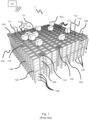
- Fig. 1 discloses a typical prior art automated storage and retrieval system 1 with a framework structure 100 and Fig. 2 and 3 disclose two different prior art container handling vehicles 201,301 suitable for operating on such a system 1.
- the framework structure 100 comprises upright members 102, horizontal members 103 and a storage volume comprising storage columns 105 arranged in rows between the upright members 102 and the horizontal members 103.
- storage columns 105 storage containers 106, also known as bins, are stacked one on top of one another to form stacks 107.
- the members 102, 103 may typically be made of metal, e.g. extruded aluminum profiles.
- the framework structure 100 of the automated storage and retrieval system 1 comprises a rail system 108 arranged across the top of framework structure 100, on which rail system 108 a plurality of container handling vehicles 201,301 are operated to raise storage containers 106 from, and lower storage containers 106 into, the storage columns 105, and also to transport the storage containers 106 above the storage columns 105.
- the rail system 108 comprises a first set of parallel rails 110 arranged to guide movement of the container handling vehicles 201,301 in a first direction X across the top of the frame structure 100, and a second set of parallel rails 111 arranged perpendicular to the first set of rails 110 to guide movement of the container handling vehicles 201,301 in a second direction Y which is perpendicular to the first direction X.
- Containers 106 stored in the columns 105 are accessed by the container handling vehicles through access openings 112 in the rail system 108.
- the container handling vehicles 201,301 can move laterally above the storage columns 105, i.e. in a plane which is parallel to the horizontal X-Y plane.
- the upright members 102 of the framework structure 100 may be used to guide the storage containers during raising of the containers out from and lowering of the containers into the columns 105.
- the stacks 107 of containers 106 are typically self-supportive.
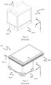
- Each prior art container handling vehicle 201,301 comprises a vehicle body 201a,301a, and first and second sets of wheels 201b,301b,201c,301c which enable the lateral movement of the container handling vehicles 201,301 in the X direction and in the Y direction, respectively.
- first and second sets of wheels 201b,301b,201c,301c which enable the lateral movement of the container handling vehicles 201,301 in the X direction and in the Y direction, respectively.
- the first set of wheels 201b,301b is arranged to engage with two adjacent rails of the first set 110 of rails
- the second set of wheels 201c,301c is arranged to engage with two adjacent rails of the second set 111 of rails.
- At least one of the sets of wheels 201b,301b,201c,301c can be lifted and lowered, so that the first set of wheels 201b,301b and/or the second set of wheels 201c,301c can be engaged with the respective set of rails 110, 111 at any one time.
- Each prior art container handling vehicle 201,301 also comprises a lifting device (not shown) for vertical transportation of storage containers 106, e.g. raising a storage container 106 from, and lowering a storage container 106 into, a storage column 105.
- the lifting device comprises one or more gripping / engaging devices which are adapted to engage a storage container 106, and which gripping / engaging devices can be lowered from the vehicle 201,301 so that the position of the gripping / engaging devices with respect to the vehicle 201,301 can be adjusted in a third direction Z which is orthogonal the first direction X and the second direction Y.
- Parts of the gripping device of the container handling vehicle 301 are shown in fig. 3 indicated with reference number 304.
- the gripping device of the container handling device 201 is located within the vehicle body 301a in Fig. 2 .
- the storage volume of the framework structure 100 has often been referred to as a grid 104, where the possible storage positions within this grid are referred to as storage cells.
- Each storage column may be identified by a position in an X- and Y-direction, while each storage cell may be identified by a container number in the X-, Y and Z-direction.
- Each prior art container handling vehicle 201,301 comprises a storage compartment or space for receiving and stowing a storage container 106 when transporting the storage container 106 across the rail system 108.
- the storage space may comprise a cavity arranged centrally within the vehicle body 201a as shown in Fig. 2 and as described in e.g. WO2015/193278A1 .
- FIG. 3 shows an alternative configuration of a container handling vehicle 301 with a cantilever construction. Such a vehicle is described in detail in e.g. NO317366 .
- the central cavity container handling vehicles 201 shown in Fig. 2 may have a footprint that covers an area with dimensions in the X and Y directions which is generally equal to the lateral extent of a storage column 105, e.g. as is described in WO2015/193278A1 .
- the term 'lateral' used herein may mean 'horizontal'.
- the central cavity container handling vehicles 101 may have a footprint which is larger than the lateral area defined by a storage column 105, e.g. as is disclosed in WO2014/090684A1 .
- the rail system 108 typically comprises rails with grooves in which the wheels of the vehicles run.
- the rails may comprise upwardly protruding elements, where the wheels of the vehicles comprise flanges to prevent derailing. These grooves and upwardly protruding elements are collectively known as tracks.
- Each rail may comprise one track, or each rail may comprise two parallel tracks.
- WO2018146304 illustrates a typical configuration of rail system 108 comprising rails and parallel tracks in both X and Y directions.
- columns 105 In the framework structure 100, a majority of the columns 105 are storage columns 105, i.e. columns 105 where storage containers 106 are stored in stacks 107. However, some columns 105 may have other purposes.
- columns 119 and 120 are such special-purpose columns used by the container handling vehicles 201,301 to drop off and/or pick up storage containers 106 so that they can be transported to an access station (not shown) where the storage containers 106 can be accessed from outside of the framework structure 100 or transferred out of or into the framework structure 100.
- such a location is normally referred to as a 'port' and the column in which the port is located may be referred to as a ⁇ port column' 119,120.
- the transportation to the access station may be in any direction, that is horizontal, tilted and/or vertical.
- the storage containers 106 may be placed in a random or dedicated column 105 within the framework structure 100, then picked up by any container handling vehicle and transported to a port column 119,120 for further transportation to an access station.
- 'tilted' means transportation of storage containers 106 having a general transportation orientation somewhere between horizontal and vertical.
- the first port column 119 may for example be a dedicated drop-off port column where the container handling vehicles 201,301 can drop off storage containers 106 to be transported to an access or a transfer station
- the second port column 120 may be a dedicated pick-up port column where the container handling vehicles 201,301 can pick up storage containers 106 that have been transported from an access or a transfer station.
- the access station may typically be a picking or a stocking station where product items are removed from or positioned into the storage containers 106.
- the storage containers 106 are normally not removed from the automated storage and retrieval system 1 but are returned into the framework structure 100 again once accessed.
- a port can also be used for transferring storage containers to another storage facility (e.g. to another framework structure or to another automated storage and retrieval system), to a transport vehicle (e.g. a train or a lorry), or to a production facility.
- a conveyor system comprising conveyors is normally employed to transport the storage containers between the port columns 119,120 and the access station.
- the conveyor system may comprise a lift device with a vertical component for transporting the storage containers 106 vertically between the port column 119,120 and the access station.
- the conveyor system may be arranged to transfer storage containers 106 between different framework structures, e.g. as is described in WO2014/075937A1 .
- one of the container handling vehicles 201,301 is instructed to retrieve the target storage container 106 from its position and transport it to the drop-off port column 119.
- This operation involves moving the container handling vehicle 201,301 to a location above the storage column 105 in which the target storage container 106 is positioned, retrieving the storage container 106 from the storage column 105 using the container handling vehicle's 201,301 lifting device (not shown), and transporting the storage container 106 to the drop-off port column 119. If the target storage container 106 is located deep within a stack 107, i.e.
- the operation also involves temporarily moving the above-positioned storage containers prior to lifting the target storage container 106 from the storage column 105.
- This step which is sometimes referred to as "digging" within the art, may be performed with the same container handling vehicle that is subsequently used for transporting the target storage container to the drop-off port column 119, or with one or a plurality of other cooperating container handling vehicles.
- the automated storage and retrieval system 1 may have container handling vehicles specifically dedicated to the task of temporarily removing storage containers from a storage column 105. Once the target storage container 106 has been removed from the storage column 105, the temporarily removed storage containers can be repositioned into the original storage column 105. However, the removed storage containers may alternatively be relocated to other storage columns.
- one of the container handling vehicles 201,301 When a storage container 106 is to be stored in one of the columns 105, one of the container handling vehicles 201,301 is instructed to pick up the storage container 106 from the pick-up port column 120 and transport it to a location above the storage column 105 where it is to be stored. After any storage containers positioned at or above the target position within the storage column stack 107 have been removed, the container handling vehicle 201,301 positions the storage container 106 at the desired position. The removed storage containers may then be lowered back into the storage column 105, or relocated to other storage columns.
- the automated storage and retrieval system 1 For monitoring and controlling the automated storage and retrieval system 1, e.g. monitoring and controlling the location of respective storage containers 106 within the framework structure 100, the content of each storage container 106; and the movement of the container handling vehicles 201,301 so that a desired storage container 106 can be delivered to the desired location at the desired time without the container handling vehicles 201,301 colliding with each other, the automated storage and retrieval system 1 comprises a control system 500 which typically is computerized and which typically comprises a database for keeping track of the storage containers 106.
- WO2017121512 describes a storage system, where the container handling vehicles are arranged with sensors that can detect the location of the vehicle, and proximity sensor to detect the location of nearby vehicles, and communicate that information to the control system 500.
- the control system communicates with a plurality of container handling vehicles and commands the container handling vehicles to form a "train" of vehicles, i.e. a plurality of container handling vehicles proximately arranged in series and arranged to move with one another in tandem.
- the assembly of the train is accomplished with help of the sensors in the container handling vehicles, by the control system's knowledge about the container handling vehicles' relative positions, or a combination of both.
- the invention is related to an automated storage and retrieval system comprising:
- An advantage of this system is that it allows a plurality of container handling vehicles to form a "train" of vehicles, i.e. a plurality of container handling vehicles proximately arranged in series and arranged to move with one another in tandem, one after the other separated by the predetermined separation.
- the target position may be any position on the rail system.
- the target position may be a final position on the rail system, such as port position, or the target position may be any intermediate positions on its way to a final position.
- the vehicle may for example be instructed to move to a first position on the rail system where the vehicle waits for another vehicle to pass, before getting instructions to move to a second position in step-by-step instructions.
- Instructing the second container handling vehicle to move with and follow the first container handling vehicle may comprise instructing the second container handling vehicle to accelerate or decelerate until the second container handling vehicle is at the predetermined separation from the first container handling vehicle based on the received position data of the positions of the first and second container handling vehicles.
- Instructing the second container handling vehicle to move with and follow the first container handling vehicle may comprise instructing the second container handling vehicle to move at a set speed based on the received position data of the positions of the first and second container handling vehicles.
- Instructing the second container handling vehicle to move with and follow the first container handling vehicle may comprise instructing the second container handling vehicle to change speed at an acceleration or deceleration based on the received position data of the positions of the first and second container handling vehicles to stay within the predetermined separation.
- Instructing the second container handling vehicle to move with and follow the first container handling vehicle may comprise instructing the second container handling vehicle to move to a position that is at the predetermined separation from the position of the first container handling vehicle based on the received position data of the positions of the first and second container handling vehicles.
- the position at the predetermined separation from the position of the first container handling vehicle that the second container handling vehicle is instructed to move to may be a position at a predetermined separation from a future position of the first container handling vehicle determined based on a current speed and heading of the first container handling vehicle.
- the signal measurements may be time of flight (TOF) measurements. More specifically, the TOF-measurements may be time difference of arrival (TDOA) measurements.
- TDOA time difference of arrival
- TWR Two Way Ranging
- the positioning node of each container handling vehicle and the at least three reference positioning nodes may be Ultra-Wideband (UWB) nodes.
- UWB is defined by the UWB PHY layer defined in the IEEE 802.15.4-2011 revision standard and provides position resolution in the centimetre range.
- the invention in a second aspect, relates to a method for controlling movement of a plurality of container handling vehicles in the system described above.
- the method comprises
- the step of instructing the second container handling vehicle to move with and follow the first container handling vehicle may comprise instructing the second container handling vehicle to accelerate or decelerate until the second container handling vehicle is at the predetermined separation from the first container handling vehicle based on the received position data of the positions of the first and second container handling vehicle.
- the step of instructing the second container handling vehicle to move with and follow the first container handling vehicle may comprise instructing the second container handling vehicle to move at a set a speed based on the received position data of the positions of the first and second container handling vehicle.
- the step of instructing the second container handling vehicle to move with and follow the first container handling vehicle may comprise instructing the second container handling vehicle to move to a position at the predetermined separation from the position of the first container handling vehicle.
- the position at the predetermined separation from the position of the first container handling vehicle that the second container handling vehicle is instructed to move to may be a position at a predetermined separation from a future position of the first container handling vehicle determined based on a current speed and heading of the first container handling vehicle.
- the position of the first container handling vehicle and the position of the second container handling vehicle may be determined using time of flight (TOF) measurements.
- TOF-measurements may be time difference of arrival (TDOA).
- the invention provides a computer program product for a control system in the system described above, wherein the computer program product comprises instructions which when executed on the control system causes the system described above to perform the method described above
- the framework structure 100 of the automated storage and retrieval system 1 is constructed in accordance with the prior art framework structure 100 described above in connection with Figs. 1-3 , i.e. a number of upright members 102 and a number of horizontal members 103, which are supported by the upright members 102, and further that the framework structure 100 comprises a first, upper rail system 108 in the X direction and Y direction.
- the framework structure 100 further comprises storage compartments in the form of storage columns 105 provided between the members 102, 103, where storage containers 106 are stackable in stacks 107 within the storage columns 105.
- the framework structure 100 can be of any size. In particular it is understood that the framework structure can be considerably wider and/or longer and/or deeper than disclosed in Fig. 1 .
- the framework structure 100 may have a horizontal extent of more than 700x700 columns and a storage depth of more than twelve containers.
- Fig. 4 illustrates two container handling vehicles 401 forming a "train" of vehicles, where the two container handling vehicles 401 move with one another at a predetermined separation S.
- Each container handling vehicle 401 comprises a positioning node 402.
- the positioning node 402 may be positioned in any suitable position exterior or interior to the container handling vehicle 401.
- the control system 500 may know the position of the positioning node 402 on the container handling vehicle 401 relative to the outer dimensions of the container handling vehicle. It may therefore be sufficient to know the separation between the two positioning nodes 402 to determine the separation S between the two container handling vehicles 401.
- the predetermined separation S may be fixed in the control system 500 or vary depending on speed of the container handling vehicles etc.
- the predetermined separation should be as small as possible, preferably smaller than 10 cm. A small predetermined separation provides for shorter trains and more effective use of available rails system space.
- Fig. 5 schematically illustrates the container handling vehicle 401 comprising a positioning node 501, and a local controller 502 adapted to control movements of the container handling vehicle.
- the local controller 502 is in communication with the control system over a wireless communication link.
- the positioning node 501 may communicate with the control system directly or via the local controller 502. In other embodiments, the positioning node 501 may only communicate with reference positioning nodes (reference positioning nodes 701, 702, 703 shown in Fig. 7 ) spaced in fixed positions on and/or proximate the rail system 108, 608.
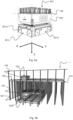
- FIG. 6 illustrates another container handling vehicle according to an embodiment of the invention.
- Figure 6a shows a container handling vehicle 601 for container delivery
- Figure 6b shows the container handling vehicle 601 in relation to an automated storage and retrieval system 1.
- the container handling vehicle 601 which is in the form of a container delivery vehicle 601, is arranged for receiving a storage container 106 in a top-down manner, and therefore comprises a container carrier 602 arranged above a vehicle body 601a to receive a storage container 106 from above.
- the container delivery vehicle 601 comprises drive means 601b in first direction X, and drive means 601c in the second direction Y, similar to that of the other aforementioned container handling vehicles 201,301, 401.
- Fig. 6b illustrates a pair of container handling vehicles 301, 601, operating on upper and lower rail systems 108, 608.
- the container delivery vehicle 601 operates on a rail system 608 below the rail system 108 of a storage grid 104 as shown.
- the delivery rail system 608 may be constructed in the same way or a similar way as the rail system 108 for the container handling vehicles 201,301, 401 described in relation to Fig. 1 .
- a container handling vehicle 301 is shown operating on the rail system 108 of the storage grid 104.
- any kind of container handling vehicle 201,301, 401 may be operated on the rail system 108 of the grid.
- the container handling vehicles 301 operating on an upper rail system 108 may thus lower storage containers down to container delivery vehicles 601 operated on the lower rail system 608.
- the container delivery vehicles 601 are typically arranged for delivery of storage containers 106 to an access point (not shown) at the periphery of the rail system 108, where the storage containers 106 may be picked.
- Fig. 7 is a top view of the rail system 108 of the system 1.
- the system 1 comprises a positioning system comprising at least three reference positioning nodes 701, 702, 703, spaced in fixed positions on and proximate the rail system 108.
- the positioning system is adapted to determine the position of the container handling vehicles 401 on the rail system 108 based on signal measurements between the positioning node 402 of each container handling vehicle 401 and the at least three reference positioning nodes 701, 702, 703.
- the reference positioning nodes 701, 702, 703 and the positioning node 402 on the container handling vehicle 401 are off-the-shelf products and various methods of signal measurements may be used to determine the position of the positioning node 402 on the grid.
- RSSI Received Signal Strength Indicator
- TOF time of flight
- the positioning node 402 of each container handling vehicle and the at least three reference positioning nodes 701, 702, 703 are Ultra-Wideband (UWB) nodes.
- UWB is defined by the UWB PHY layer defined in the IEEE 802.15.4-2011 revision standard.
- UWB utilizes a train of impulses rather than a modulated sine wave to transmit information. This characteristic makes it perfect for precise ranging applications. Since the pulse occupies such a wide frequency band, its rising edge is very steep and this allows the receiver to very accurately measure the arrival time of the signal. The pulses themselves are very narrow, typically no more than two nanoseconds. Due to the nature of the signals, UWB pulses can be distinguished even in noisy environments, and the signals are resistant to multipath effects. All of these traits give UWB a big advantage over traditional narrowband signals in case of ranging capabilities. Also due to a strict spectral mask, the transmission power lies at the noise floor, which means that UWB does not interfere with other radio communication systems operating in the same frequency bands, since it just increases the overall noise floor. The framework structure 100 of the system 1 is susceptible for multipath effects and UWB positioning is suitable to overcome those problems. UWB positioning systems has a resolution in the decimeter range, and so offers much finer resolution than for the known WiFi positioning systems.
- UWB positioning systems use one of two different methods for Time of Flight measurements for positioning.
- One method is two-way ranging, TWR.
- TWR three messages have to be sent, the positioning node 402 sends a poll message to one of the at least three reference positioning nodes 701, 702, 703, the poll message comprising a time of sending Poll, TSP.
- the one of the at least three reference positioning nodes 701, 702, 703, records the time of poll reception, TRP, and replies with a response message at a time TSR.
- the positioning node 402 records the response message time, TRR.
- the positioning node 402 sends a final message, comprising TSP, TRR and the time of sending final message, TSF, to the one of the at least three reference positioning nodes 701, 702, 703, which records the time of reception of the final message, TRF. It is then possible to calculate the TOF and the distance.
- multilateration techniques may be used to determine the position of the positioning node 402 on the grid 108.
- TOF TRR ⁇ TSP ⁇ TSR ⁇ TRP + TRF ⁇ TSR ⁇ TSF ⁇ TRR / 4
- Distance TOF ⁇ speed of light
- the one of the at least three reference positioning nodes 701, 702, 703, may determine the TOF and distance by itself, or it may forward the information to a real time location server, RTLS, in communication with the at least three reference positioning nodes 701, 702, 703, for the RTLS to perform the determination.
- the determined distance may also be sent in a message back to positioning node 402.
- the RTLS of the positioning system repeatedly reports position data of the position of each of the positioning nodes 402 to the control system 500.
- a second method for Time of Flight measurements for UWB positioning systems is Time Difference of Arrival, TDoA, that is based on precise measurements of time difference between signals arrival to the at least three reference positioning nodes 701, 702, 703.
- TDoA Time Difference of Arrival
- the positioning node 402 transmits in a regular interval (refresh rate) a short Blink message.
- the Blink message is received by all reference positioning nodes 701, 702, 703 within the communication range of the positioning node 402.
- Each of the reference positioning nodes 701, 702, 703 records the time of Blink message reception, e.g.
- the RTLS-server uses multilateration techniques to determine the position of the positioning node 402 based on the time difference of arrival TR701, TR702, TR703.
- TDoA An advantage of TDoA over TWR is that the positioning node 402 doesn't communicate with the reference positioning nodes 701, 702, 703. While TWR requires 9 messages to localize the positioning node 402, TDoA requires only one. Furthermore, the positioning node 402 uses only a short time to send the Blink message, therefore a high number of positioning nodes 402 may transmit a Blink message within the regular interval (refresh rate). TDoA may therefore be advantageously used when the number of container handling vehicles 201,301, 401, 601 to be positioned increases.
- the automated storage and retrieval system 1 comprises, as discussed above, a computerized control system 500 which comprises a database for keeping track of the storage containers 106.
- the control system 500 is adapted to communicate with the local controller 502 in each container handling vehicle 201, 301, 401, 601, e.g. to send instructions to the container handling vehicle on where to move on the grid 108, or where to pick up or drop a storage container 106.
- the control system 500 is also adapted to communicate with the positioning system, e.g. the RTLS-server, to receive real time position data for each of the container handling vehicles 201, 301, 401, 601.
- the positioning system provides the control system 500 with knowledge about the container handling vehicles' relative positions such that the control system 500 may instruct the container handling vehicles to form a "train" of vehicles, i.e. a plurality of container handling vehicles proximately arranged in series and arranged to move with one another in tandem.
- the control system 500 is adapted to instruct a first container handling vehicle to move to a target position, repeatedly receive position data from the positioning system of a position of the first container handling vehicle and repeatedly receive position data from the positioning system of a position of a second container handling vehicle, and instruct the second container handling vehicle to move with and follow the first container handling vehicle within a predetermined separation S from the first container handling vehicle based on the received position data of the positions of the first and second container vehicles.
- the predetermined separation between the first container handling vehicle and the second container handling vehicle may be fixed in the control system 500 or vary depending on speed of the container handling vehicles etc.
- the predetermined separation may be viewed as a target separation between the first container handling vehicle and the second container handling vehicle. As the vehicles move independently of each other the instantaneous separation may vary within a given tolerance of the predetermined separation.
- the second container handling vehicle may be instructed to speed up if it falls behind, or slow down if it comes too close.
- the given tolerance may be plus/minus 25%, plus/minus 10%, plus/minus 5%, plus/minus 1%, and may vary depending on the configuration of the automated storage and retrieval system. Various factors as the type of container handling vehicles, the total number of container handling vehicles etc. may influence the given tolerance.
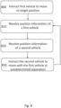
- Fig. 8 is a flow diagram schematically representing the steps of a method for operating an automated storage and retrieval system 1.
- the method is typically initiated by a step 800 where the control system 500 instructs a first container handling vehicle 401A to move to a target position TA.
- a target position may typically be a storage column, on rail system 108,608.
- the local controller of the first container handling vehicle 401 receives the instructions and initiates movement of the first container handling vehicle 401A towards the target position TA.
- the control system 500 knows that it intends to create a train of container handling vehicles moving together towards the target position TA.
- the train comprises at least a second container handling vehicle 401B.
- the control system 500 receives the position data from the positioning system of a position of the first container handling vehicle 401A and receives the position data from the positioning system of a position of the second container handling vehicle 401B.
- the order of receiving the position information of the first container handling vehicle 401A prior to receiving the position information of the second container handling vehicle 401A is arbitrary chosen for the simplicity of illustration.
- the step 820 may instead precede the step 810, or step 810 and 820 may occur substantially at the same time.
- the positioning system determines the positions of the first container handling vehicle 401A and the second container handling vehicle 401B by performing signal measurements between the positioning node 402 of each container handling vehicle 401A, 401B and the at least three reference positioning nodes 701, 702, 703.
- the control system 500 instructs the second container handling vehicle 401B to move with and follow the first container handling vehicle 401B at a predetermined separation S from the first container handling vehicle 401A.
- the local controller of the second container handling vehicle 401B receives the instructions and initiates movement of the second container handling vehicle 401B towards the first container handling vehicle 401A until it is at the predetermined separation S and continues to move with the first container handling vehicle at the predetermined separation S.
- the second container handling vehicle 401B follows the first container handling vehicle 401A.
- the control system 500 repeatedly receives the position data from the positioning system of the position of the first container handling vehicle 401A and repeatedly receives the position data from the positioning system of the position of the second container handling vehicle 401B, as illustrated by the method returning to step 810.
- the control system may send instructions to the second container handling vehicle 401B to again instruct the second container handling vehicle 401B to move with the first container handling vehicle 401A at the predetermined separation S.
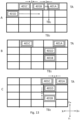
- Fig. 9 is a schematic top view of a rail system 108, illustrating steps of a method where two container handling vehicles 401A, 401B controlled by the control system 500 are forming a train of vehicles.
- the two container handling vehicles 401A, 401B are initially in adjacent cells on the rail system 108 as shown in in Fig. 9A .
- the control system instructs a first container handling vehicle 401A to move towards a target position TA.
- the target position may be any position on the rail system.
- the target position may be a final position on the rail system, such as port position, or the target position may be any intermediate positions on its way to a final position.
- the vehicle may for example be instructed to move to a first position on the rail system where the vehicle waits for another vehicle to pass, before getting instructions to move to a second position in step-by-step instructions.
- the control system 500 receives position data from the positioning system of a position of the first container handling vehicle 401A and position data from the positioning system of a position of a second container handling vehicle 401B. Once the separation between the first and second container handling vehicle is within a predetermined separation S, as shown in Fig 9B , the second container handling vehicle 401A is instructed to move with and follow the first container handling vehicle within the predetermined separation S.
- the first container handling vehicle 401A acts as the locomotive, and the position of the second container handling vehicle 401B is adjusted relative to the first container handling vehicle 401A by the control system when the position data received from the position system indicates that the separation is different from the predetermined separation S.
- the second container handling vehicle 401B is instructed to stop in a position at the predetermined separation S as illustrated in Fig. 9D .
- the target position of TA may not be the final position of the first container handling vehicle 401A, so the second container handling vehicle 401B is kept at the predetermined separation in case the first container handling vehicle 401A begins to move again towards a new target position (not shown). If the target position TA was the final position for the first container handling vehicle 401A, the control system 500 could instruct the second container handling vehicle 401B to move to a position adjacent the first container handling vehicle 401A.
- the second container handling vehicle 401B arrives at its own target position TB (not shown) prior to the first container handling vehicle 401A arriving at the target position TA, then the second container handling vehicle 401B would stop at the target position TB. That is, the second container handling vehicle stops moving with the first container handling vehicle 401A when arriving at TB.
- Instructing the second container handling vehicle to move with and to follow the first container handling vehicle may comprise repeatedly instructing the second container handling vehicle 401B to move to a position that is at the predetermined separation S from the position of the first container handling vehicle 401A. That is, every time the controls system 500 receives position data from the positioning system of the position of the first container handling vehicle 401A, the control system 500 determines a new position the second container handling vehicle 401B should be in to be within the predetermined separation S from the position of the first container handling vehicle 401A.
- the control system 500 may instruct the second container handling vehicle 401B to move with and to follow the first container handling vehicle 401A at a set speed.
- the control system may instruct the second container handling vehicle 401B to accelerate or decelerate until the second container handling vehicle 401B again is at the predetermined separation S from the first container handling vehicle 401A.
- the second container handling vehicle 401B may be instructed to move at a set speed to move with and to follow the first container handling vehicle 401A.
- Instructing the second container handling vehicle to move with and to follow the first container handling vehicle may prior to instructing the second container handling vehicle 401B to move with and follow the first container handling vehicle 401A, comprise instructing the second container handling vehicle 401B to move to a position that is at the predetermined separation S from the position of the first container handling vehicle 401A.
- the position at the predetermined separation S from the position of the first container handling vehicle 401A that the second container handling vehicle 401B is instructed to move to is a position at a predetermined separation S from a future position of the first container handling vehicle 401A.
- the future position of the first container handling vehicle 401A may be determine based on a current speed and heading of the first container handling vehicle 401A. Alternatively, as will be discussed below with reference to Fig.
- the control system 500 knows where it will send the first container handling vehicle 401A and may determine to send the second container handling vehicle 401B to a position at predetermined separation S of that future position of the first container handling vehicle 401A. In some situations, this may save the time needed to form a train of vehicles.
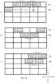
- Fig. 10 is a schematic top view of a rail system 108, illustrating steps of a method where two container handling vehicles 401A, 401B controlled by the control system 500 are forming a "train" of vehicles.
- the two container handling vehicles 401A, 401B are initially in different rows and columns on the rail system 108 as shown in in Fig. 10A .
- the control system instructs a first container handling vehicle 401A to move to a second target position TA 2 .
- the control system 500 receives position data from the positioning system of a position of the first container handling vehicle 401A and position data from the positioning system of the position of the second container handling vehicle 401B.
- the control system 500 instructs the first container handling vehicle 401A to first move two rows in the Y- direction to a first target position TA 1 and knows that it from there will instruct the first container handling vehicle 401A to move two columns in the X+ direction to the second target position TA 2 . Knowing where the first container handling device 401A will be in the future, the control system also instructs the second container handling vehicle 401B to move to a position that is at the predetermined separation S from the future position TA 1 of the first container handling vehicle 401A, as illustrated in Fig. 10B .
- the future position of the first container handling vehicle 401A may be determined based on a current speed and heading of the first container handling vehicle 401A.
- the instructions to the second container handling vehicle 401B may be timed such that the second container handling vehicle 401B reaches its position just in time for the first container handling vehicle to arrive.
- the instructions to the second container handling vehicle 401B may be timed such that the second container handling vehicle 401b arrives prior to the first container handling vehicle 401A arrives at the first target position TA 1 .
- the control system 500 instructs the first container handling vehicle 401A and the second container handling vehicle 401B to move as shown in Fig. 10C and 10D as described above with reference to Fig. 9C and 9D .
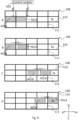
- Fig. 11 is a schematic top view of a rail system 108, illustrating steps of a method where three container handling vehicles 401A, 401B, 401C controlled by the control system 500 are forming a "train" of vehicles.
- the container handling vehicles 401B, 401C move with and follow the first container handling vehicle 401A with a predetermined separation S between each pair of container handling vehicles.
- the predetermined separation S may be the same for each pair of container handling vehicles or vary for each of the pairs. Any number of container handling vehicles may move together with the first container handling vehicle 401A.
- Fig. 12 is a schematic top view of a rail system 108, illustrating steps of a method where a plurality of container handling vehicles controlled by the control system 500 forming a single train are split into two separate trains heading for different target positions.
- the uppermost row may in one exemplary implementation function as a motorway for large trains moving many container handling vehicles.
- the large train may be split into smaller trains of container handling vehicles moving on side roads, where the train may move slower and/or yield for other moving container handling vehicles.
- Three container handling vehicles 401A, 401B, 401C are initially on the same row of the rails system 108 as shown in Fig. 12A , moving in the X+ direction toward a target position TA (outside the illustrated rail section) for the first container handling vehicle 401A.
- the fourth container handling vehicle 401D is on another row. Two container handling vehicles 401B, 401C initially move with the first container handling vehicle 401A as discussed with reference to Fig. 10 .
- the control system 500 knows that the second container handling device 401B and the fourth container handling device 401D are heading towards a different target position TB 2 (outside the illustrated rail section) compared to the first container handling vehicle 401A.
- the controls system 500 may also know or determine that it would be advantageous to move the second container handling vehicle 401B and the fourth container handling vehicle 401D together as a train towards the target position TB 2 .
- the control system 500 instructs the second container handling vehicle to move to a target position TB 1 , that is, one row in the Y- direction.
- the control system 500 instructs the fourth container handling vehicle 401D to move to a position that is at the predetermined separation S from the future position TB 1 , as illustrated in Fig. 12B .
- the fourth container handling vehicle 401D may reach the position just in time, or prior to the second container handling vehicle 401B arrives at TB 1 .
- the fourth container handling vehicle 401D may in this example have to accelerate to arrive at the predetermined separation S from TB 1 in time.
- the control system 500 also receives position data from the positioning system of the position of the first container handling vehicle 401A and position data from the positioning system of the position of the third container handling vehicle 401C and instructs the third container handing vehicle 401C to move with the first container handling vehicle 401A at the predetermined separation S. In this case, that would include first accelerating the third container handling vehicle 401C to catch up with the first container handling vehicle 401A, as illustrated in Fig. 12C . Furthermore, the fourth container handling vehicle 401D is instructed to move with the second container handling vehicle 401B at the predetermined separation S towards the target position TB 2 .
- the same methodology could be used to include a smaller train or a single container handling device into another train.
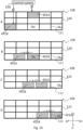
- Fig. 13 is a schematic top view of a rail system 108, illustrating steps of a method where a plurality of container handling vehicles controlled by the control system 500 forming a single train are split into two separate trains heading for different target positions.
- Three container handling vehicles 401A, 401B, 401C are initially on the same row of the rails system 108 as shown in Fig. 13A , moving in the X+ direction toward a target position TA (outside the illustrated rail section) for the first container handling vehicle 401A.
- the fourth container handling vehicle 401D is on another row.
- Two container handling vehicles 401B, 401C initially move with the first container handling vehicle 401A as discussed with reference to Fig. 10 .
- the control system 500 knows that the second container handling device 401B and the fourth container handling device 401D are heading towards a different target position TB 2 (outside the illustrated rail section) compared to the first container handling vehicle 401A.
- the controls system 500 may also know or determine that it would be advantageous to move the second container handling vehicle 401B and the fourth container handling vehicle 401D together as a train towards the target position TB 2 .
- the control system 500 instructs the second container handling vehicle to move to a target position TB 1 , that is, two rows in the Y- direction.
- the control system 500 instructs the fourth container handling vehicle 401D to move to a position that is at the predetermined separation S from the future position TB 1 , as illustrated in Fig. 13B .
- the control system 500 knows that the second container handling vehicle 401B will have to pass this position before the fourth container handing vehicle 401B reaches that position, and times the fourth container handling vehicle 401B to arrive at the position after the second container handling vehicle 401D arrived at the target position TB 1 .
- the fourth container handling vehicle 401D may in this example have to decelerate to arrive at the predetermined separation S from TB 1 after the second container handling vehicle 401B. As illustrated in Fig.
- the fourth container handling vehicle 401D may arrive in position closer than the predetermined separation S, before the second container handling vehicle 401B and the fourth container handling vehicle 401D is instructed to move together in the same direction Y- as illustrated in Fig. 13C .
Landscapes
- Engineering & Computer Science (AREA)
- Mechanical Engineering (AREA)
- Physics & Mathematics (AREA)
- Mathematical Physics (AREA)
- Warehouses Or Storage Devices (AREA)
- Automatic Disk Changers (AREA)
- Electric Propulsion And Braking For Vehicles (AREA)
Claims (16)
- Automatisches Lager- und Entnahmesystem (1), umfassend:ein Schienensystem (108, 308) mit einem ersten Satz paralleler Schienen (110), die sich in einer ersten Richtung (X) erstrecken, und einem zweiten Satz paralleler Schienen (111), die sich in einer zweiten Richtung (Y) erstrecken, wobei die zweite Richtung (Y) senkrecht zur ersten Richtung (X) verläuft;mehrere Behälterhandhabungsfahrzeuge (201, 301, 401, 601) auf dem Schienensystem (108, 308), die dazu betreibbar sind, Lagerbehälter (106) zu handhaben, wobei jedes Behälterhandhabungsfahrzeug (201, 301, 401, 601) Folgendes umfasst:einen Positionsbestimmungsknoten (502), undeine lokale Steuerung, die dazu ausgelegt ist, Bewegungen des Behälterhandhabungsfahrzeugs (201, 301, 401, 601) zu steuern;ein Positionsbestimmungssystem, das mindestens drei Referenzpositionsbestimmungsknoten (701, 702, 703) umfasst, die in festen Positionen auf und/oder nahe dem Schienensystem (108, 308) beabstandet sind, wobei das Positionsbestimmungssystem dazu ausgelegt ist, eine Position auf dem Schienensystem für jedes der Behälterhandhabungsfahrzeuge (201, 301, 401, 601) basierend auf Signalmessungen zwischen dem Positionsbestimmungsknoten (502) jedes Behälterhandhabungsfahrzeugs (201, 301, 401, 601) und den mindestens drei Referenzpositionsbestimmungsknoten (701, 702, 703) zu bestimmen; undein Steuersystem (500), das dazu ausgelegt ist, mit jeder lokalen Steuerung in jedem Behälterhandhabungsfahrzeug (201, 301, 401, 601) und dem Positionsbestimmungssystem zu kommunizieren, wobei das Steuersystem (500) zu Folgendem ausgelegt ist:- Anweisen eines ersten Behälterhandhabungsfahrzeugs, sich zu einer Zielposition zu bewegen,- wiederholtes Empfangen von Positionsdaten von dem Positionsbestimmungssystem zu einer Position des ersten Behälterhandhabungsfahrzeugs und wiederholtes Empfangen von Positionsdaten von dem Positionsbestimmungssystem zu einer Position eines zweiten Behälterhandhabungsfahrzeugs, und- Anweisen des zweiten Behälterhandhabungsfahrzeugs, sich basierend auf den empfangenen Positionsdaten zu den Positionen des ersten und des zweiten Behälterhandhabungsfahrzeugs mit dem ersten Behälterhandhabungsfahrzeug innerhalb einer vorbestimmten Entfernung (S) von dem ersten Behälterhandhabungsfahrzeug zu bewegen und diesem zu folgen.
- System nach Anspruch 1, wobei das Anweisen des zweiten Behälterhandhabungsfahrzeugs, sich mit dem ersten Behälterhandhabungsfahrzeug zu bewegen und diesem zu folgen, Anweisen des zweiten Behälterhandhabungsfahrzeugs, basierend auf den empfangenen Positionsdaten zu den Positionen des ersten und des zweiten Behälterhandhabungsfahrzeugs zu beschleunigen oder zu verlangsamen, bis sich das zweite Behälterhandhabungsfahrzeug in der vorbestimmten Entfernung (S) von dem ersten Behälterhandhabungsfahrzeug befindet, umfasst.
- System nach einem der vorhergehenden Ansprüche, wobei das Anweisen des zweiten Behälterhandhabungsfahrzeugs, sich mit dem ersten Behälterhandhabungsfahrzeug zu bewegen und diesem zu folgen, Anweisen des zweiten Behälterhandhabungsfahrzeugs, sich basierend auf den empfangenen Positionsdaten zu den Positionen des ersten und des zweiten Behälterhandhabungsfahrzeugs mit einer festgelegten Geschwindigkeit zu bewegen, umfasst.
- System nach einem der vorhergehenden Ansprüche, wobei das Anweisen des zweiten Behälterhandhabungsfahrzeugs, sich mit dem ersten Behälterhandhabungsfahrzeug zu bewegen und diesem zu folgen, Anweisen des zweiten Behälterhandhabungsfahrzeugs, sich zu einer Position zu bewegen, die sich in der vorbestimmten Entfernung (S) von der Position des ersten Behälterhandhabungsfahrzeugs befindet, umfasst.
- System nach Anspruch 4, wobei die Position in der vorbestimmten Entfernung (S) von der Position des ersten Behälterhandhabungsfahrzeugs, in die sich zu bewegen das zweite Behälterhandhabungsfahrzeug angewiesen wird, eine Position in einer vorbestimmten Entfernung (S) von einer zukünftigen Position des ersten Behälterhandhabungsfahrzeugs ist, die basierend auf einer aktuellen Geschwindigkeit und einem aktuellen Kurs des ersten Behälterhandhabungsfahrzeugs bestimmt wird.
- System nach einem der vorhergehenden Ansprüche, wobei die Signalmessungen Laufzeit(TOF)-Messungen sind.
- System nach Anspruch 6, wobei die TOF-Messungen Ankunftszeitdifferenz(TDOA)-Messungen sind.
- System nach einem der vorhergehenden Ansprüche, wobei der Positionsbestimmungsknoten jedes Behälterhandhabungsfahrzeugs und die mindestens drei Referenzpositionsbestimmungsknoten Ultrabreitband(UWB)-Knoten sind.
- Verfahren zum Steuern einer Bewegung mehrerer Behälterhandhabungsfahrzeuge (201, 301, 601) in dem System nach den Ansprüchen 1-8, wobei das Verfahren Folgendes umfasst- Anweisen des ersten Behälterhandhabungsfahrzeugs, sich zu der Zielposition zu bewegen,- wiederholtes Empfangen der Positionsdaten von dem Positionsbestimmungssystem zu einer Position des ersten Behälterhandhabungsfahrzeugs und wiederholtes Empfangen der Positionsdaten von dem Positionsbestimmungssystem zu einer Position des zweiten Behälterhandhabungsfahrzeugs, und- Anweisen des zweiten Behälterhandhabungsfahrzeugs, sich basierend auf den empfangenen Positionsdaten zu den Positionen des ersten und des zweiten Behälterhandhabungsfahrzeugs mit dem ersten Behälterhandhabungsfahrzeug innerhalb einer vorbestimmten Entfernung (S) von dem ersten Behälterhandhabungsfahrzeug zu bewegen und diesem zu folgen.
- Verfahren nach Anspruch 9, wobei der Schritt des Anweisens des zweiten Behälterhandhabungsfahrzeugs, sich mit dem ersten Behälterhandhabungsfahrzeug zu bewegen und diesem zu folgen, Anweisen des zweiten Behälterhandhabungsfahrzeugs, basierend auf den empfangenen Positionsdaten zu den Positionen des ersten und des zweiten Behälterhandhabungsfahrzeugs zu beschleunigen oder zu verlangsamen, bis sich das zweite Behälterhandhabungsfahrzeug in der vorbestimmten Entfernung (S) von dem ersten Behälterhandhabungsfahrzeug befindet, umfasst.
- Verfahren nach Anspruch 9 oder 10, wobei der Schritt des Anweisens des zweiten Behälterhandhabungsfahrzeugs, sich mit dem ersten Behälterhandhabungsfahrzeug zu bewegen und diesem zu folgen, Anweisen des zweiten Behälterhandhabungsfahrzeugs, sich basierend auf den empfangenen Positionsdaten zu den Positionen des ersten und des zweiten Behälterhandhabungsfahrzeugs mit einer festgelegten Geschwindigkeit zu bewegen, umfasst.
- Verfahren nach einem der Ansprüche 9-11, wobei der Schritt des Anweisens des zweiten Behälterhandhabungsfahrzeugs, sich mit dem ersten Behälterhandhabungsfahrzeug zu bewegen und diesem zu folgen, Anweisen des zweiten Behälterhandhabungsfahrzeugs, sich zu einer Position in der vorbestimmten Entfernung (S) von der Position des ersten Behälterhandhabungsfahrzeugs zu bewegen, umfasst.
- Verfahren nach Anspruch 12, wobei die Position in der vorbestimmten Entfernung (S) von der Position des ersten Behälterhandhabungsfahrzeugs, in die sich zu bewegen das zweite Behälterhandhabungsfahrzeug angewiesen wird, eine Position in einer vorbestimmten Entfernung (S) von einer zukünftigen Position des ersten Behälterhandhabungsfahrzeugs ist, die basierend auf einer aktuellen Geschwindigkeit und einem aktuellen Kurs des ersten Behälterhandhabungsfahrzeugs bestimmt wird.
- Verfahren nach einem der Ansprüche 9-13, ferner umfassend Bestimmen der Position des ersten Behälterhandhabungsfahrzeugs und der Position des zweiten Behälterhandhabungsfahrzeugs unter Verwendung von Laufzeit(TOF)-Messungen.
- Verfahren nach Anspruch 14, wobei die TOF-Messungen Ankunftszeitdifferenz(TDOA)-Messungen sind.
- Computerprogrammprodukt für ein Steuersystem (500) in dem System nach den Ansprüchen 1-8, wobei das Computerprogrammprodukt Anweisungen umfasst, die, wenn sie auf dem Steuersystem (500) ausgeführt werden, das System nach den Ansprüchen 1-8 veranlassen, das Verfahren nach einem der Ansprüche 9-15 durchzuführen.
Applications Claiming Priority (2)
| Application Number | Priority Date | Filing Date | Title |
|---|---|---|---|
| NO20200743A NO346304B1 (en) | 2020-06-25 | 2020-06-25 | System and method of operating an automated storage and retrieval system |
| PCT/EP2021/065319 WO2021259632A1 (en) | 2020-06-25 | 2021-06-08 | System and method of operating an automated storage and retrieval system |
Publications (3)
| Publication Number | Publication Date |
|---|---|
| EP4172071A1 EP4172071A1 (de) | 2023-05-03 |
| EP4172071C0 EP4172071C0 (de) | 2025-05-14 |
| EP4172071B1 true EP4172071B1 (de) | 2025-05-14 |
Family
ID=76421996
Family Applications (1)
| Application Number | Title | Priority Date | Filing Date |
|---|---|---|---|
| EP21731999.5A Active EP4172071B1 (de) | 2020-06-25 | 2021-06-08 | System und verfahren zum betrieb eines automatischen regalbedienungssystems |
Country Status (10)
| Country | Link |
|---|---|
| US (1) | US12371260B2 (de) |
| EP (1) | EP4172071B1 (de) |
| JP (1) | JP2023530758A (de) |
| KR (1) | KR20230026457A (de) |
| CN (1) | CN115734922A (de) |
| CA (1) | CA3181894A1 (de) |
| ES (1) | ES3037741T3 (de) |
| NO (1) | NO346304B1 (de) |
| PL (1) | PL4172071T3 (de) |
| WO (1) | WO2021259632A1 (de) |
Families Citing this family (3)
| Publication number | Priority date | Publication date | Assignee | Title |
|---|---|---|---|---|
| NO347763B1 (en) * | 2022-05-03 | 2024-03-18 | Autostore Tech As | Local positioning system |
| CN114803384B (zh) * | 2022-05-30 | 2024-04-02 | 博众精工科技股份有限公司 | 一种运动跟随防碰撞方法、装置和换电站 |
| NO348278B1 (en) * | 2022-12-21 | 2024-11-04 | Autostore Tech As | Method and system for moving automated vehicles of an automated storage system |
Citations (1)
| Publication number | Priority date | Publication date | Assignee | Title |
|---|---|---|---|---|
| WO2017121512A1 (en) * | 2016-01-14 | 2017-07-20 | Autostore Technology AS | Storage system with multiple robots |
Family Cites Families (24)
| Publication number | Priority date | Publication date | Assignee | Title |
|---|---|---|---|---|
| US3786929A (en) * | 1971-11-01 | 1974-01-22 | Conco Inc | Warehousing system using slowdown and stop bin indicators |
| NO317366B1 (no) | 1999-07-01 | 2004-10-18 | Autostore As | Lagringsanlegg med fjernstyrte vogner med to hjulsett og heisinnretning for drift på skinner anlagt i kryss over kolonner av lagringsenheter som er adskilt med vertikale profilstolper |
| WO2007132951A1 (en) | 2006-05-11 | 2007-11-22 | Posco | Method and apparatus for control and safe braking in personal rapid transit systems with in-track linear induction motors |
| US8276739B2 (en) * | 2007-01-25 | 2012-10-02 | Bastian Material Handling, Llc | Three-dimensional automated pick module |
| FR2928980B1 (fr) | 2008-03-18 | 2013-03-01 | Snpe Materiaux Energetiques | Verin leve capot avec agencement de freinage en retour desamorcable |
| JP5263585B2 (ja) * | 2008-07-11 | 2013-08-14 | 株式会社ダイフク | 物品保管設備 |
| US9701475B2 (en) * | 2009-03-11 | 2017-07-11 | Parking Kit Ltd. | Modular storage system |
| JP5448102B2 (ja) * | 2011-02-02 | 2014-03-19 | 株式会社ダイフク | 搬送用走行体の走行制御方法 |
| GB201202878D0 (en) | 2012-02-20 | 2012-04-04 | Jaguar Cars | Improvements in vehicle autonomous cruise control |
| NO334806B1 (no) | 2012-11-13 | 2014-06-02 | Jakob Hatteland Logistics As | Lagringssystem |
| NO335839B1 (no) | 2012-12-10 | 2015-03-02 | Jakob Hatteland Logistics As | Robot for transport av lagringsbeholdere |
| NO337544B1 (no) | 2014-06-19 | 2016-05-02 | Jakob Hatteland Logistics As | Fjernstyrt kjøretøysammenstilling for å plukke opp lagringsbeholdere fra et lagringssystem |
| US20160016731A1 (en) * | 2014-07-16 | 2016-01-21 | Sergey N. Razumov | Loading desired container sequence onto board of container carriage in storage system |
| NO340577B1 (en) | 2015-09-04 | 2017-05-15 | Jakob Hatteland Logistics As | Method for fetching a target bin stored in a storage system and a storage system which includes a control device operating in accordance with the method |
| NO20170216A1 (en) | 2017-02-13 | 2018-08-14 | Autostore Tech As | Rail arrangement for wheeled vehicles in a storage system |
| NO346327B1 (en) * | 2017-05-16 | 2022-06-07 | Autostore Tech As | Automated storage and retrieval system |
| US11360465B2 (en) * | 2017-05-16 | 2022-06-14 | Autostore Technology AS | Automated storage and retrieval system |
| CN107479513B (zh) * | 2017-07-05 | 2020-05-19 | 纳恩博(北京)科技有限公司 | 一种定位方法及系统、电子设备 |
| US10568064B2 (en) * | 2017-08-23 | 2020-02-18 | Locix, Inc. | Systems and methods for precise radio frequency localization using time difference of arrival |
| NO346519B1 (en) * | 2017-11-02 | 2022-09-19 | Autostore Tech As | An automated storage and retrieval system, use of a multi trolley vehicle on the system and a method of operating the system |
| CN111492257B (zh) * | 2017-12-21 | 2023-11-14 | 奥卡多创新有限公司 | 定位装置、通信系统和方法 |
| WO2019238670A1 (en) * | 2018-06-12 | 2019-12-19 | Autostore Technology AS | A method of operating an automated storage and retrieval system |
| CN109348426A (zh) | 2018-11-26 | 2019-02-15 | 黎国溥 | 一种基于uwb的跟随系统及方法 |
| NO20190884A1 (en) | 2019-07-12 | 2021-01-13 | Autostore Tech As | A method and system for autonomous controlling of movements of container handling vehicles operating in an automated storage and retrieval system |
-
2020
- 2020-06-25 NO NO20200743A patent/NO346304B1/en unknown
-
2021
- 2021-06-08 CN CN202180045357.XA patent/CN115734922A/zh active Pending
- 2021-06-08 CA CA3181894A patent/CA3181894A1/en active Pending
- 2021-06-08 KR KR1020237002083A patent/KR20230026457A/ko active Pending
- 2021-06-08 US US18/001,353 patent/US12371260B2/en active Active
- 2021-06-08 WO PCT/EP2021/065319 patent/WO2021259632A1/en not_active Ceased
- 2021-06-08 PL PL21731999.5T patent/PL4172071T3/pl unknown
- 2021-06-08 ES ES21731999T patent/ES3037741T3/es active Active
- 2021-06-08 EP EP21731999.5A patent/EP4172071B1/de active Active
- 2021-06-08 JP JP2022579003A patent/JP2023530758A/ja active Pending
Patent Citations (1)
| Publication number | Priority date | Publication date | Assignee | Title |
|---|---|---|---|---|
| WO2017121512A1 (en) * | 2016-01-14 | 2017-07-20 | Autostore Technology AS | Storage system with multiple robots |
Also Published As
| Publication number | Publication date |
|---|---|
| WO2021259632A1 (en) | 2021-12-30 |
| US20230234779A1 (en) | 2023-07-27 |
| CA3181894A1 (en) | 2021-12-30 |
| JP2023530758A (ja) | 2023-07-19 |
| CN115734922A (zh) | 2023-03-03 |
| EP4172071C0 (de) | 2025-05-14 |
| ES3037741T3 (en) | 2025-10-06 |
| PL4172071T3 (pl) | 2025-09-22 |
| US12371260B2 (en) | 2025-07-29 |
| EP4172071A1 (de) | 2023-05-03 |
| KR20230026457A (ko) | 2023-02-24 |
| NO346304B1 (en) | 2022-05-30 |
| NO20200743A1 (en) | 2021-12-27 |
Similar Documents
| Publication | Publication Date | Title |
|---|---|---|
| EP4172071B1 (de) | System und verfahren zum betrieb eines automatischen regalbedienungssystems | |
| AU2018391812B2 (en) | Positioning device, communications system and method | |
| EP3807183B1 (de) | Verfahren zum betrieb eines automatischen regalbedienungssystems | |
| EP4078317B1 (de) | Ferngesteuertes fahrzeug mit einer anordnung zur vorwarnung und verfolgung einer position des fahrzeugs | |
| TWI465871B (zh) | 移行台車系統和移行台車系統之通訊方法 | |
| HK40083720A (en) | System and method of operating an automated storage and retrieval system | |
| EP4248290B1 (de) | Verfahren, system und computerprogrammprodukt zur steuerung der bewegung einer vielzahl von containerhandhabungsfahrzeugen | |
| US20250282548A1 (en) | Local positioning system for vehicles on a grid of an automated storage system | |
| EP4656556A1 (de) | Roboterfahrzeug | |
| EP4639300A1 (de) | System und wartung zur zustandsbasierten wartung eines ports | |
| WO2024231287A1 (en) | Automated vehicle with directional antenna | |
| JPWO2021259632A5 (de) | ||
| NO20221372A1 (en) | System and maintenance for condition based maintenance of port | |
| HK40064819A (en) | A method and system for autonomous controlling of movements of container handling vehicles operating in an automated storage and retrieval system |
Legal Events
| Date | Code | Title | Description |
|---|---|---|---|
| STAA | Information on the status of an ep patent application or granted ep patent |
Free format text: STATUS: UNKNOWN |
|
| STAA | Information on the status of an ep patent application or granted ep patent |
Free format text: STATUS: THE INTERNATIONAL PUBLICATION HAS BEEN MADE |
|
| PUAI | Public reference made under article 153(3) epc to a published international application that has entered the european phase |
Free format text: ORIGINAL CODE: 0009012 |
|
| STAA | Information on the status of an ep patent application or granted ep patent |
Free format text: STATUS: REQUEST FOR EXAMINATION WAS MADE |
|
| 17P | Request for examination filed |
Effective date: 20230109 |
|
| AK | Designated contracting states |
Kind code of ref document: A1 Designated state(s): AL AT BE BG CH CY CZ DE DK EE ES FI FR GB GR HR HU IE IS IT LI LT LU LV MC MK MT NL NO PL PT RO RS SE SI SK SM TR |
|
| DAV | Request for validation of the european patent (deleted) | ||
| DAX | Request for extension of the european patent (deleted) | ||
| STAA | Information on the status of an ep patent application or granted ep patent |
Free format text: STATUS: EXAMINATION IS IN PROGRESS |
|
| 17Q | First examination report despatched |
Effective date: 20240125 |
|
| GRAP | Despatch of communication of intention to grant a patent |
Free format text: ORIGINAL CODE: EPIDOSNIGR1 |
|
| STAA | Information on the status of an ep patent application or granted ep patent |
Free format text: STATUS: GRANT OF PATENT IS INTENDED |
|
| INTG | Intention to grant announced |
Effective date: 20241219 |
|
| GRAS | Grant fee paid |
Free format text: ORIGINAL CODE: EPIDOSNIGR3 |
|
| GRAA | (expected) grant |
Free format text: ORIGINAL CODE: 0009210 |
|
| STAA | Information on the status of an ep patent application or granted ep patent |
Free format text: STATUS: THE PATENT HAS BEEN GRANTED |
|
| AK | Designated contracting states |
Kind code of ref document: B1 Designated state(s): AL AT BE BG CH CY CZ DE DK EE ES FI FR GB GR HR HU IE IS IT LI LT LU LV MC MK MT NL NO PL PT RO RS SE SI SK SM TR |
|
| REG | Reference to a national code |
Ref country code: GB Ref legal event code: FG4D |
|
| REG | Reference to a national code |
Ref country code: CH Ref legal event code: EP |
|
| REG | Reference to a national code |
Ref country code: IE Ref legal event code: FG4D |
|
| REG | Reference to a national code |
Ref country code: DE Ref legal event code: R096 Ref document number: 602021030778 Country of ref document: DE |
|
| U01 | Request for unitary effect filed |
Effective date: 20250523 |
|
| U07 | Unitary effect registered |
Designated state(s): AT BE BG DE DK EE FI FR IT LT LU LV MT NL PT RO SE SI Effective date: 20250530 |
|
| PGFP | Annual fee paid to national office [announced via postgrant information from national office to epo] |
Ref country code: GB Payment date: 20250612 Year of fee payment: 5 |
|
| U20 | Renewal fee for the european patent with unitary effect paid |
Year of fee payment: 5 Effective date: 20250612 |
|
| REG | Reference to a national code |
Ref country code: ES Ref legal event code: FG2A Ref document number: 3037741 Country of ref document: ES Kind code of ref document: T3 Effective date: 20251006 |
|
| PGFP | Annual fee paid to national office [announced via postgrant information from national office to epo] |
Ref country code: ES Payment date: 20250714 Year of fee payment: 5 |
|
| PG25 | Lapsed in a contracting state [announced via postgrant information from national office to epo] |
Ref country code: NO Free format text: LAPSE BECAUSE OF FAILURE TO SUBMIT A TRANSLATION OF THE DESCRIPTION OR TO PAY THE FEE WITHIN THE PRESCRIBED TIME-LIMIT Effective date: 20250814 Ref country code: GR Free format text: LAPSE BECAUSE OF FAILURE TO SUBMIT A TRANSLATION OF THE DESCRIPTION OR TO PAY THE FEE WITHIN THE PRESCRIBED TIME-LIMIT Effective date: 20250815 |
|
| PGFP | Annual fee paid to national office [announced via postgrant information from national office to epo] |
Ref country code: PL Payment date: 20250602 Year of fee payment: 5 |
|
| PG25 | Lapsed in a contracting state [announced via postgrant information from national office to epo] |
Ref country code: HR Free format text: LAPSE BECAUSE OF FAILURE TO SUBMIT A TRANSLATION OF THE DESCRIPTION OR TO PAY THE FEE WITHIN THE PRESCRIBED TIME-LIMIT Effective date: 20250514 |
|
| PGFP | Annual fee paid to national office [announced via postgrant information from national office to epo] |
Ref country code: CH Payment date: 20250701 Year of fee payment: 5 |
|
| PG25 | Lapsed in a contracting state [announced via postgrant information from national office to epo] |
Ref country code: RS Free format text: LAPSE BECAUSE OF FAILURE TO SUBMIT A TRANSLATION OF THE DESCRIPTION OR TO PAY THE FEE WITHIN THE PRESCRIBED TIME-LIMIT Effective date: 20250814 |
|
| PGFP | Annual fee paid to national office [announced via postgrant information from national office to epo] |
Ref country code: CZ Payment date: 20250522 Year of fee payment: 5 |
|
| PG25 | Lapsed in a contracting state [announced via postgrant information from national office to epo] |
Ref country code: IS Free format text: LAPSE BECAUSE OF FAILURE TO SUBMIT A TRANSLATION OF THE DESCRIPTION OR TO PAY THE FEE WITHIN THE PRESCRIBED TIME-LIMIT Effective date: 20250914 |