EP4170881A1 - Steuerung eines elektrischen stromsystemwandlers - Google Patents
Steuerung eines elektrischen stromsystemwandlers Download PDFInfo
- Publication number
- EP4170881A1 EP4170881A1 EP22196867.0A EP22196867A EP4170881A1 EP 4170881 A1 EP4170881 A1 EP 4170881A1 EP 22196867 A EP22196867 A EP 22196867A EP 4170881 A1 EP4170881 A1 EP 4170881A1
- Authority
- EP
- European Patent Office
- Prior art keywords
- electrical
- converter
- network
- transistors
- power system
- Prior art date
- Legal status (The legal status is an assumption and is not a legal conclusion. Google has not performed a legal analysis and makes no representation as to the accuracy of the status listed.)
- Pending
Links
- 230000000694 effects Effects 0.000 claims abstract description 13
- 238000000034 method Methods 0.000 claims abstract description 12
- 239000003990 capacitor Substances 0.000 claims description 21
- 239000004065 semiconductor Substances 0.000 claims description 16
- 238000009499 grossing Methods 0.000 claims description 2
- 230000002441 reversible effect Effects 0.000 description 9
- 238000002347 injection Methods 0.000 description 5
- 239000007924 injection Substances 0.000 description 5
- 230000004044 response Effects 0.000 description 5
- 230000001360 synchronised effect Effects 0.000 description 5
- 230000001141 propulsive effect Effects 0.000 description 4
- 230000002457 bidirectional effect Effects 0.000 description 3
- 230000004907 flux Effects 0.000 description 3
- 239000000446 fuel Substances 0.000 description 3
- 230000002829 reductive effect Effects 0.000 description 3
- 238000007599 discharging Methods 0.000 description 2
- 230000003068 static effect Effects 0.000 description 2
- XUIMIQQOPSSXEZ-UHFFFAOYSA-N Silicon Chemical compound [Si] XUIMIQQOPSSXEZ-UHFFFAOYSA-N 0.000 description 1
- 230000009471 action Effects 0.000 description 1
- 230000002411 adverse Effects 0.000 description 1
- 230000008859 change Effects 0.000 description 1
- 238000002485 combustion reaction Methods 0.000 description 1
- 230000006835 compression Effects 0.000 description 1
- 238000007906 compression Methods 0.000 description 1
- 238000001514 detection method Methods 0.000 description 1
- 238000010586 diagram Methods 0.000 description 1
- 238000000605 extraction Methods 0.000 description 1
- 238000009434 installation Methods 0.000 description 1
- 239000000203 mixture Substances 0.000 description 1
- 230000008569 process Effects 0.000 description 1
- 239000000047 product Substances 0.000 description 1
- 230000001681 protective effect Effects 0.000 description 1
- 230000009467 reduction Effects 0.000 description 1
- 230000000717 retained effect Effects 0.000 description 1
- 229910052710 silicon Inorganic materials 0.000 description 1
- 239000010703 silicon Substances 0.000 description 1
- HBMJWWWQQXIZIP-UHFFFAOYSA-N silicon carbide Chemical compound [Si+]#[C-] HBMJWWWQQXIZIP-UHFFFAOYSA-N 0.000 description 1
- 239000007858 starting material Substances 0.000 description 1
- 239000013589 supplement Substances 0.000 description 1
Images


Classifications
-
- F—MECHANICAL ENGINEERING; LIGHTING; HEATING; WEAPONS; BLASTING
- F02—COMBUSTION ENGINES; HOT-GAS OR COMBUSTION-PRODUCT ENGINE PLANTS
- F02C—GAS-TURBINE PLANTS; AIR INTAKES FOR JET-PROPULSION PLANTS; CONTROLLING FUEL SUPPLY IN AIR-BREATHING JET-PROPULSION PLANTS
- F02C6/00—Plural gas-turbine plants; Combinations of gas-turbine plants with other apparatus; Adaptations of gas- turbine plants for special use
-
- H—ELECTRICITY
- H02—GENERATION; CONVERSION OR DISTRIBUTION OF ELECTRIC POWER
- H02M—APPARATUS FOR CONVERSION BETWEEN AC AND AC, BETWEEN AC AND DC, OR BETWEEN DC AND DC, AND FOR USE WITH MAINS OR SIMILAR POWER SUPPLY SYSTEMS; CONVERSION OF DC OR AC INPUT POWER INTO SURGE OUTPUT POWER; CONTROL OR REGULATION THEREOF
- H02M1/00—Details of apparatus for conversion
- H02M1/32—Means for protecting converters other than automatic disconnection
-
- B—PERFORMING OPERATIONS; TRANSPORTING
- B64—AIRCRAFT; AVIATION; COSMONAUTICS
- B64D—EQUIPMENT FOR FITTING IN OR TO AIRCRAFT; FLIGHT SUITS; PARACHUTES; ARRANGEMENTS OR MOUNTING OF POWER PLANTS OR PROPULSION TRANSMISSIONS IN AIRCRAFT
- B64D27/00—Arrangement or mounting of power plant in aircraft; Aircraft characterised thereby
- B64D27/02—Aircraft characterised by the type or position of power plant
- B64D27/10—Aircraft characterised by the type or position of power plant of gas-turbine type
-
- B—PERFORMING OPERATIONS; TRANSPORTING
- B64—AIRCRAFT; AVIATION; COSMONAUTICS
- B64D—EQUIPMENT FOR FITTING IN OR TO AIRCRAFT; FLIGHT SUITS; PARACHUTES; ARRANGEMENTS OR MOUNTING OF POWER PLANTS OR PROPULSION TRANSMISSIONS IN AIRCRAFT
- B64D27/00—Arrangement or mounting of power plant in aircraft; Aircraft characterised thereby
- B64D27/02—Aircraft characterised by the type or position of power plant
- B64D27/24—Aircraft characterised by the type or position of power plant using steam, electricity, or spring force
-
- H—ELECTRICITY
- H02—GENERATION; CONVERSION OR DISTRIBUTION OF ELECTRIC POWER
- H02J—CIRCUIT ARRANGEMENTS OR SYSTEMS FOR SUPPLYING OR DISTRIBUTING ELECTRIC POWER; SYSTEMS FOR STORING ELECTRIC ENERGY
- H02J3/00—Circuit arrangements for ac mains or ac distribution networks
- H02J3/001—Methods to deal with contingencies, e.g. abnormalities, faults or failures
-
- H—ELECTRICITY
- H02—GENERATION; CONVERSION OR DISTRIBUTION OF ELECTRIC POWER
- H02J—CIRCUIT ARRANGEMENTS OR SYSTEMS FOR SUPPLYING OR DISTRIBUTING ELECTRIC POWER; SYSTEMS FOR STORING ELECTRIC ENERGY
- H02J3/00—Circuit arrangements for ac mains or ac distribution networks
- H02J3/01—Arrangements for reducing harmonics or ripples
-
- H—ELECTRICITY
- H02—GENERATION; CONVERSION OR DISTRIBUTION OF ELECTRIC POWER
- H02J—CIRCUIT ARRANGEMENTS OR SYSTEMS FOR SUPPLYING OR DISTRIBUTING ELECTRIC POWER; SYSTEMS FOR STORING ELECTRIC ENERGY
- H02J3/00—Circuit arrangements for ac mains or ac distribution networks
- H02J3/02—Circuit arrangements for ac mains or ac distribution networks using a single network for simultaneous distribution of power at different frequencies; using a single network for simultaneous distribution of ac power and of dc power
-
- H—ELECTRICITY
- H02—GENERATION; CONVERSION OR DISTRIBUTION OF ELECTRIC POWER
- H02M—APPARATUS FOR CONVERSION BETWEEN AC AND AC, BETWEEN AC AND DC, OR BETWEEN DC AND DC, AND FOR USE WITH MAINS OR SIMILAR POWER SUPPLY SYSTEMS; CONVERSION OF DC OR AC INPUT POWER INTO SURGE OUTPUT POWER; CONTROL OR REGULATION THEREOF
- H02M1/00—Details of apparatus for conversion
- H02M1/0045—Converters combining the concepts of switch-mode regulation and linear regulation, e.g. linear pre-regulator to switching converter, linear and switching converter in parallel, same converter or same transistor operating either in linear or switching mode
-
- H—ELECTRICITY
- H02—GENERATION; CONVERSION OR DISTRIBUTION OF ELECTRIC POWER
- H02M—APPARATUS FOR CONVERSION BETWEEN AC AND AC, BETWEEN AC AND DC, OR BETWEEN DC AND DC, AND FOR USE WITH MAINS OR SIMILAR POWER SUPPLY SYSTEMS; CONVERSION OF DC OR AC INPUT POWER INTO SURGE OUTPUT POWER; CONTROL OR REGULATION THEREOF
- H02M1/00—Details of apparatus for conversion
- H02M1/0048—Circuits or arrangements for reducing losses
- H02M1/0054—Transistor switching losses
- H02M1/0058—Transistor switching losses by employing soft switching techniques, i.e. commutation of transistors when applied voltage is zero or when current flow is zero
-
- H—ELECTRICITY
- H02—GENERATION; CONVERSION OR DISTRIBUTION OF ELECTRIC POWER
- H02M—APPARATUS FOR CONVERSION BETWEEN AC AND AC, BETWEEN AC AND DC, OR BETWEEN DC AND DC, AND FOR USE WITH MAINS OR SIMILAR POWER SUPPLY SYSTEMS; CONVERSION OF DC OR AC INPUT POWER INTO SURGE OUTPUT POWER; CONTROL OR REGULATION THEREOF
- H02M1/00—Details of apparatus for conversion
- H02M1/36—Means for starting or stopping converters
-
- H—ELECTRICITY
- H02—GENERATION; CONVERSION OR DISTRIBUTION OF ELECTRIC POWER
- H02M—APPARATUS FOR CONVERSION BETWEEN AC AND AC, BETWEEN AC AND DC, OR BETWEEN DC AND DC, AND FOR USE WITH MAINS OR SIMILAR POWER SUPPLY SYSTEMS; CONVERSION OF DC OR AC INPUT POWER INTO SURGE OUTPUT POWER; CONTROL OR REGULATION THEREOF
- H02M5/00—Conversion of ac power input into ac power output, e.g. for change of voltage, for change of frequency, for change of number of phases
- H02M5/40—Conversion of ac power input into ac power output, e.g. for change of voltage, for change of frequency, for change of number of phases with intermediate conversion into dc
- H02M5/42—Conversion of ac power input into ac power output, e.g. for change of voltage, for change of frequency, for change of number of phases with intermediate conversion into dc by static converters
- H02M5/44—Conversion of ac power input into ac power output, e.g. for change of voltage, for change of frequency, for change of number of phases with intermediate conversion into dc by static converters using discharge tubes or semiconductor devices to convert the intermediate dc into ac
- H02M5/453—Conversion of ac power input into ac power output, e.g. for change of voltage, for change of frequency, for change of number of phases with intermediate conversion into dc by static converters using discharge tubes or semiconductor devices to convert the intermediate dc into ac using devices of a triode or transistor type requiring continuous application of a control signal
- H02M5/458—Conversion of ac power input into ac power output, e.g. for change of voltage, for change of frequency, for change of number of phases with intermediate conversion into dc by static converters using discharge tubes or semiconductor devices to convert the intermediate dc into ac using devices of a triode or transistor type requiring continuous application of a control signal using semiconductor devices only
- H02M5/4585—Conversion of ac power input into ac power output, e.g. for change of voltage, for change of frequency, for change of number of phases with intermediate conversion into dc by static converters using discharge tubes or semiconductor devices to convert the intermediate dc into ac using devices of a triode or transistor type requiring continuous application of a control signal using semiconductor devices only having a rectifier with controlled elements
-
- H—ELECTRICITY
- H02—GENERATION; CONVERSION OR DISTRIBUTION OF ELECTRIC POWER
- H02M—APPARATUS FOR CONVERSION BETWEEN AC AND AC, BETWEEN AC AND DC, OR BETWEEN DC AND DC, AND FOR USE WITH MAINS OR SIMILAR POWER SUPPLY SYSTEMS; CONVERSION OF DC OR AC INPUT POWER INTO SURGE OUTPUT POWER; CONTROL OR REGULATION THEREOF
- H02M7/00—Conversion of ac power input into dc power output; Conversion of dc power input into ac power output
- H02M7/02—Conversion of ac power input into dc power output without possibility of reversal
- H02M7/04—Conversion of ac power input into dc power output without possibility of reversal by static converters
- H02M7/12—Conversion of ac power input into dc power output without possibility of reversal by static converters using discharge tubes with control electrode or semiconductor devices with control electrode
- H02M7/21—Conversion of ac power input into dc power output without possibility of reversal by static converters using discharge tubes with control electrode or semiconductor devices with control electrode using devices of a triode or transistor type requiring continuous application of a control signal
- H02M7/217—Conversion of ac power input into dc power output without possibility of reversal by static converters using discharge tubes with control electrode or semiconductor devices with control electrode using devices of a triode or transistor type requiring continuous application of a control signal using semiconductor devices only
- H02M7/219—Conversion of ac power input into dc power output without possibility of reversal by static converters using discharge tubes with control electrode or semiconductor devices with control electrode using devices of a triode or transistor type requiring continuous application of a control signal using semiconductor devices only in a bridge configuration
-
- B—PERFORMING OPERATIONS; TRANSPORTING
- B64—AIRCRAFT; AVIATION; COSMONAUTICS
- B64D—EQUIPMENT FOR FITTING IN OR TO AIRCRAFT; FLIGHT SUITS; PARACHUTES; ARRANGEMENTS OR MOUNTING OF POWER PLANTS OR PROPULSION TRANSMISSIONS IN AIRCRAFT
- B64D2221/00—Electric power distribution systems onboard aircraft
-
- B64D27/026—
-
- F—MECHANICAL ENGINEERING; LIGHTING; HEATING; WEAPONS; BLASTING
- F05—INDEXING SCHEMES RELATING TO ENGINES OR PUMPS IN VARIOUS SUBCLASSES OF CLASSES F01-F04
- F05D—INDEXING SCHEME FOR ASPECTS RELATING TO NON-POSITIVE-DISPLACEMENT MACHINES OR ENGINES, GAS-TURBINES OR JET-PROPULSION PLANTS
- F05D2270/00—Control
- F05D2270/01—Purpose of the control system
- F05D2270/05—Purpose of the control system to affect the output of the engine
- F05D2270/053—Explicitly mentioned power
-
- Y—GENERAL TAGGING OF NEW TECHNOLOGICAL DEVELOPMENTS; GENERAL TAGGING OF CROSS-SECTIONAL TECHNOLOGIES SPANNING OVER SEVERAL SECTIONS OF THE IPC; TECHNICAL SUBJECTS COVERED BY FORMER USPC CROSS-REFERENCE ART COLLECTIONS [XRACs] AND DIGESTS
- Y02—TECHNOLOGIES OR APPLICATIONS FOR MITIGATION OR ADAPTATION AGAINST CLIMATE CHANGE
- Y02T—CLIMATE CHANGE MITIGATION TECHNOLOGIES RELATED TO TRANSPORTATION
- Y02T50/00—Aeronautics or air transport
- Y02T50/60—Efficient propulsion technologies, e.g. for aircraft
Definitions
- This disclosure relates to electrical power systems, more particularly to the control of power electronics converters in electrical power systems.
- the electrical power systems may be of particular utility in transport applications including but not limited to aerospace.
- Some proposed more electric and hybrid electric platforms include DC electrical networks which receive electrical power from engine-driven electrical machines via AC to DC converters (i.e., rectifiers).
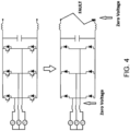
- the upper circuit of Figure 4 illustrates a typical arrangement in which a three-phase electrical generator, which may be coupled with and driven by a spool of a gas turbine engine, is connected with a DC network via a two-level AC-DC converter.
- Each phase leg of the converter has two transistors (e.g. , IGBTs), each of which is connected in anti-parallel with an associated diode.
- IGBTs To rectify the AC output of the generator, for each phase leg current is commutated between the upper diode and the lower transistor, with each conducting for half of each AC cycle.
- the lower circuit of Figure 4 illustrates the effect of a fault in the DC network which places a low impedance across the network terminals.
- both the DC and AC sides of the converter assume a low voltage condition, which in the limit may be zero Volts. In this condition there is no voltage to reverse bias the diodes, which means the AC-DC converter loses control and in effect reverts to being an uncontrolled diode rectifier.
- the level of current which will be supplied to the DC network in the faulted condition will therefore depend mainly on the voltage generated by and the impedance of the electrical machine.
- the converter In some applications it is acceptable for the converter to operate as an uncontrolled diode rectifier when there is a DC network fault. In other applications, however, including aerospace applications, this mode of operation may be highly undesirable because the electrical machines may generate high voltages and/or may have low impedances, such that the high levels of fault current will be supplied to the fault site in the DC network.
- the invention is directed to an electrical power system, a method of controlling an electrical power system and a controller for an electrical power system as set out in the appended claims.
- an electrical power system comprising: an electrical machine operable to output AC; a DC electrical network; a power electronics converter connected between the AC output of the electrical machine and the DC electrical network and comprising a plurality of transistors and associated diodes connected in parallel with the transistors; and a controller configured to control switching of the transistors of the converter so that, during normal operation of the electrical power system, the converter rectifies the AC output of the electrical machine to supply the DC electrical network with DC electrical power.
- the controller is further configured, responsive to a determination to the effect there is a fault in the DC electrical network, to control a voltage source to inject a voltage to bias the diodes of the converter, and to control the switching of the transistors to control a level of current supplied to the faulted DC electrical network.
- the system By responding to a DC network fault with the injection of a diode-biasing voltage the system retains the ability to commutate current between the diodes and transistors despite the collapse of the DC network voltage.
- This allows the converter to be switched into states in which the fault current can be reduced to zero, or at least to an average level below the full fault current level that would otherwise be conducted to the DC network. Not only does this protect loads in the DC network from a potentially very high fault current, it can provide an opportunity to perform protective measures, e.g. , the opening of circuit breaking components (eg. , mechanical or semiconductor contactors or circuit breakers) in the DC network, whilst the network is subject to zero or low current. This may reduce problems associated with e.g.
- the ability to control the DC side fault current may be particularly advantageous when a variable voltage and/or variable frequency generator (eg. , a permanent magnet generator) is employed as the fault current produced by the converter operating as an uncontrolled diode rectifier may vary significantly with generator shaft speed.
- a variable voltage and/or variable frequency generator eg. , a permanent magnet generator
- the voltage source may comprise one or more of the following connectable with the power electronics converter and DC electrical network: a resistor; a capacitor; an inductor; and/or a semiconductor switching component.
- Said component(s) may be connected in series with ( eg. , between) the DC output of the converter and the DC electrical network.
- Said component(s) may be connected in parallel with a controllable switch, whereby the component(s) may be selectively connected upon determination of a fault.
- controlling the voltage source to inject the voltage to bias the diodes may comprise operating the semiconductor switching component in a linear operating region to produce the biasing voltage.
- a transistor may be operated for short periods of time in its linear region so as to develop a higher than normal voltage to produce the diode commutating voltage.
- controlling the voltage source to inject the voltage to bias the diodes may comprise controlling the charge or discharge of the capacitor to produce the biasing voltage.
- the voltage source may comprise a circuit (eg. , a bridge circuit such as a half-bridge or full-bridge) incorporating semiconductor switching components (e.g. , transistors) and a capacitor.
- the controller may control the switching of the semiconductor switching components of the circuit so as to charge or discharge the capacitor to bias the diodes in response to the determination there is a fault in the DC network.
- the electrical power system may further comprise a soft-start circuit, and the soft-start circuit may comprise the voltage source.
- the soft-start circuit may comprise a resistor and switch (eg. , a semiconductor switching device such as a transistor) connected in parallel.
- the switch may be opened to connect the resistor to the converter and DC electrical network.
- the switch is a transistor
- the transistor may be operated for short periods of time in its linear region so as to develop a higher-than-normal voltage to produce the diode commuting voltage.
- the use of a soft-start circuit to provide the voltage source function may be particularly convenient because the electrical power system may already include a soft-start circuit. Thus, no additional components or equipment need be provided.
- Controlling the switching of the transistors to control the level of current supplied from the electrical machine to the faulted DC electrical network may comprise: switching the transistors of the converter to a crow-bar configuration in which current from the electrical machine does not flow to the DC network.
- Zero fault current is supplied to the DC network in the crow-bar configuration and the current is instead contained within the converter ( eg. , within one half of the bridge of a bridge-configured converter).
- Controlling the switching of the transistors to control the level of current supplied from the electrical machine to the faulted DC electrical network may comprise: repeatedly switching the transistors between the crow-bar configuration and a rectifier configuration in which current from the electrical machine does flow to the DC network. In this case the time spent in the crow-bar configuration reduces the time-averaged current supplied to the DC network.
- Controlling the switching of the transistors to control the level of current supplied from the electrical machine to the faulted DC electrical network may comprise: modulating a pulse width modulation (PWM) control parameter to control the level of current supplied from the electrical machine to the faulted DC electrical network.
- PWM pulse width modulation
- a frequency and/or pulse width (i.e., duty cycle) of a PWM signal used to control the switching of the transistors may be adjusted to control ( eg. , reduce) the level of current supplied to the DC network.
- the electrical power system may further comprise a filter for smoothing a waveform of the current supplied to the faulted DC electrical network.
- the filter may be a low-pass filter.
- the diodes of the converter may be separate from the transistors, with the transistors being of any suitable known type (eg. , IGBTs, MOSFETs). In other examples the diodes may be body diodes of MOSFETs. Those skilled in the art will understand the term "body diode” to be the diode character inherent to a MOSFET, which can effectively be considered to be a diode connected in parallel with the bi-directional switchable conduction path between the source and drain of the MOSFET.
- the electrical machine may be of any suitable type.
- the electrical machine may for example be a permanent magnet machine, a wound field machine, or a switched reluctance machine.
- the electrical machine may have a plurality of phases; and the power electronics converter may comprises a phase leg for each one of the plurality of phases of the electrical machine.
- Each phase leg may comprise: a first transistor and associated parallel diode connected between a phase connection of the electrical machine and a first DC output of the converter; and a second transistor and associated parallel diode connected between the phase connection of the electrical machine and a second DC output of the converter.
- the first and second DC outputs of the converter may be connected with the DC electrical network. Any number of phases greater than or equal to two may be used. In one specific example the number of phases is three, and in another specific example the number of phases is four.
- a method of controlling an electrical power system comprising an electrical machine, a DC electrical network and a power electronics converter connected between the electrical machine and the DC electrical network.
- the method comprises: generating AC using the electrical machine and supplying the AC to an input of the converter; controlling switching of transistors of the converter to rectify the AC input to a DC output and supply the DC output to the DC electrical network; determining a condition to the effect that there is a fault in the DC electrical network; responsive to the determination, controlling a voltage source to inject a voltage to bias diodes of the converter; and after controlling the voltage source to inject a voltage to bias diodes of the converter, controlling switching of the transistors of the converter to control a level of current supplied to the DC electrical network.
- Controlling switching of the transistors of the converter to control the level of current supplied to the DC electrical network may comprise: switching the transistors of the converter to a crow-bar configuration in which current from the electrical machine does not flow to the DC network.
- Controlling switching of the transistors of the converter to control the level of current supplied to the DC electrical network may comprise: repeatedly switching the transistors between the crow-bar configuration and a rectifier configuration in which current from the electrical machine does flow to the DC network.
- Controlling switching of the transistors of the converter to control the level of current supplied to the DC electrical network may comprise: modulating a pulse width modulation control parameter to control the level of current supplied from the electrical machine to the faulted DC electrical network.
- the method may further comprise, after controlling switching of the transistors of the converter to control the level of current supplied to the DC electrical network: opening one more circuit breakers or contactors in the DC electrical network to isolate the fault in the DC network. In this way the fault and/or other DC network components can be isolated.
- opening the contactor after controlling the level of current problems such as contactor arcing can be reduced. Such problems may be particularly reduced if the opening is performed at zero current, e.g. , when the converter is in the crow-bar configuration.
- a controller for an electrical power system configured to: during normal operation of the electrical power system, control switching of a plurality of transistors of a power electronics converter to rectify AC received by the converter from an electrical machine; and responsive to a determination to the effect there is a fault in a DC electrical network connected to a DC side of the converter, control a voltage source to inject a voltage to bias diodes of the converter, and control the switching of the transistors to control a level of current supplied to the faulted DC electrical network.
- the controller may be implemented as a single controller or multiple separate ( eg. , distributed) controllers. Thus the controller may be or may form part of a control system.
- the controller may be implemented in software, hardware or a combination of the two.
- the controller may be or may be a functional module of an Engine Electronic Controller (EEC) or a Full Authority Digital Engine Controller (FADEC).
- EEC Engine Electronic Controller
- FADEC Full Authority Digital Engine Controller
- an aircraft power and propulsion system comprising: a gas turbine engine; and an electrical power system according to the first aspect.
- the electrical machine of the electrical power system is mechanically coupled with a spool of the gas turbine engine.
- the power electronics converter may be a unidirectional AC to DC converter (i.e., a rectifier) or a bidirectional AC-DC converter capable of operating as either a rectifier or an inverter depending on an operating mode of the electrical machine.
- an aircraft comprising the power and propulsion system of the fourth aspect.
- the aircraft may be a solely gas-turbine-powered aircraft (eg. , a more electric aircraft) or a hybrid electric aircraft.
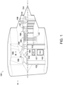
- FIG. 1 A general arrangement of an engine 101 for an aircraft is shown in Figure 1 .
- the engine 101 is of turbofan configuration, and thus comprises a ducted fan 102 that receives intake air A and generates two pressurised airflows: a bypass flow B which passes axially through a bypass duct 103 and a core flow C which enters a core gas turbine.
- the core gas turbine comprises, in axial flow series, a low-pressure compressor 104, a high-pressure compressor 105, a combustor 106, a high-pressure turbine 107, and a low-pressure turbine 108.
- the core flow C is compressed by the low-pressure compressor 104 and is then directed into the high-pressure compressor 105 where further compression takes place.
- the compressed air exhausted from the high-pressure compressor 105 is directed into the combustor 106 where it is mixed with fuel and the mixture is combusted.
- the resultant hot combustion products then expand through, and thereby drive, the high-pressure turbine 107 and in turn the low-pressure turbine 108 before being exhausted to provide a small proportion of the overall thrust.
- the high-pressure turbine 107 drives the high-pressure compressor 105 via an interconnecting shaft.
- the low-pressure turbine 108 drives the low-pressure compressor 104 via another interconnecting shaft.
- the high-pressure compressor 105, high-pressure turbine 107, and associated interconnecting shaft form part of a high-pressure spool of the engine 101.
- the low-pressure compressor 104, low-pressure turbine 108, and associated interconnecting shaft form part of a low-pressure spool of the engine 101.
- Such nomenclature will be familiar to those skilled in the art.
- Those skilled in the art will also appreciate that whilst the illustrated engine has two spools, other gas turbine engines have a different number of spools, e.g. , three spools.
- the fan 102 is driven by the low-pressure turbine 108 via a reduction gearbox in the form of a planetary-configuration epicyclic gearbox 109.
- the low-pressure turbine 108 is connected with a sun gear of the gearbox 109.
- the sun gear is meshed with a plurality of planet gears located in a rotating carrier, which planet gears are in turn meshed with a static ring gear.
- the rotating carrier drives the fan 102 via a fan shaft 110.
- a star-configuration epicyclic gearbox in which the planet carrier is static and the ring gear rotates and provides the output
- the gearbox 109 may be omitted entirely so that the fan 102 is driven directly by the low-pressure turbine 108.
- the engine 101 of Figure 1 comprises one or more rotary electrical machines, generally capable of operating both as a motor and as a generator.
- the number and arrangement of the rotary electrical machines will depend to some extent on the desired functionality.
- Some embodiments of the engine 101 include a single rotary electrical machine 111 driven by the high-pressure spool, for example by a core-mounted accessory drive 112 of conventional configuration. Such a configuration facilitates the generation of electrical power for the engine and the aircraft and the driving of the high-pressure spool to facilitate starting of the engine in place of an air turbine starter.
- FIG. 1 Other embodiments, including the one shown in Figure 1 , comprise both a first rotary electrical machine 111 coupled with the high-pressure spool and a second rotary electrical machine 113 coupled with the low pressure spool.
- first and second rotary machines 111, 113 connected by power electronics, can facilitate the transfer of mechanical power between the high and lower pressure spools to improve operability, fuel consumption etc.
- the first rotary electrical machine 111 is driven by the high-pressure spool by a core-mounted accessory drive 112 of conventional configuration.
- the first electrical machine 111 may be mounted coaxially with the turbomachinery in the engine 101.
- the first electrical machine 111 may be mounted axially in line with the duct between the low- and high-pressure compressors 104 and 105.
- the second electrical machine 113 is mounted in the tail cone 114 of the engine 101 coaxially with the turbomachinery and is coupled to the low-pressure turbine 108.
- the second rotary electrical machine 113 may be located axially in line with low-pressure compressor 104, which may adopt a bladed disc or bladed drum configuration to provide space for the second rotary electrical machine 113. It will of course be appreciated by those skilled in the art that any other suitable location for the first and (if present) second electrical machines may be adopted.
- the first and second electrical machines 111, 113 are connected with power electronics. Extraction of power from or application of power to the electrical machines is performed by a power electronics module (PEM) 115.
- PEM power electronics module
- the PEM 115 is mounted on the fan case 116 of the engine 101, but it will be appreciated that it may be mounted elsewhere such as on the core of the gas turbine, or in the vehicle to which the engine 101 is attached, for example.
- Control of the PEM 115 and of the first and second electrical machines 111 and 113 is in the present example performed by an engine electronic controller (EEC) 117.
- EEC engine electronic controller
- the EEC 117 is a full-authority digital engine controller (FADEC), the configuration of which will be known and understood by those skilled in the art. It therefore controls all aspects of the engine 101, i.e., both of the core gas turbine and the first and second electrical machines 111 and 113. In this way, the EEC 117 may holistically respond to both thrust demand and electrical power demand.
- FADEC full-authority digital engine controller
- the one or more rotary electrical machines 111, 113 and the power electronics 115 may be configured to output to or receive electric power from one, two or more dc busses.
- the dc busses allow for the distribution of electrical power to other engine electrical loads and to electrical loads on the airframe.
- gas turbine engine 101 described above may be regarded as a 'more electric' gas turbine engine because of the increased role of the electrical machines 111, 113 compared with those of conventional gas turbines.
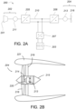
- FIG 2A illustrates an exemplary propulsion system 200 of a hybrid electric aircraft.
- the propulsion system 200 includes a generator set 202 comprising an engine 201 and electrical generator 211, and a battery pack 203. Both the generator set 202 and the battery pack 203 are used as energy sources to power a motor-driven propulsor 204, an example of which is shown in Figure 2B .
- the illustrated propulsion system 200 further comprises an AC/DC converter 205, a dc distribution bus 210, a DC/AC converter 206 and a DC/DC converter 207. It will be appreciated that whilst one generator set 202 and one propulsor 204 are illustrated in this example, a propulsion system 200 may include more than one generator set 202 and/or one or more propulsor 204.
- a shaft or spool of the engine 201 is coupled to and drives the rotation of a shaft of the generator 211 which thereby produces alternating current.
- the AC/DC converter 205 which faces the generator 211, converts the alternating current into direct current which is fed to various electrical systems and loads via the dc distribution bus 210. These electrical systems include non-propulsive loads (not shown in Figure 2A ) and the motor 213 which drives the propulsor 204 via the DC/AC converter 206.
- the battery pack 203 which may be made up of a number of battery modules connected in series and/or parallel, is connected to the dc distribution bus 210 via the DC/DC converter 207.
- the DC/DC converter 207 converts between a voltage of the battery pack 203 and a voltage of the dc distribution bus 210. In this way, the battery pack 203 can replace or supplement the power provided by the generator set 202 (by discharging and thereby feeding the DC distribution bus 210) or can be charged using the power provided by the generator set 202 (by being fed by the dc distribution bus 210).
- the propulsor 204 takes the form of a ducted fan.
- the fan 216 is enclosed within a fan duct 219 defined within a nacelle 221, and is mounted to a core nacelle 215.
- the fan 216 is driven by the electrical machine 213 via a drive shaft 214, both of which may also be thought of as components of the propulsor 204.
- a gearbox 220 is provided between the electrical machine 213 and the drive shaft 214.
- the electrical machine 213 is supplied with electric power from a power source, for example the generator set 202 and/or the battery 203 via the dc bus 210.
- the electrical machine 213 of the propulsor, and indeed the electrical machine 211 of the generator set 202, may be of any suitable type, for example of the permanent magnet synchronous type.
- propulsion system 200 of Figures 2A-B will recognise the propulsion system 200 of Figures 2A-B to be of the series hybrid type.
- Other hybrid electric propulsion systems are of the parallel type, while still others are of the turboelectric type or have features of more than one type.
- the configuration of the more electric engine 101 of Figure 1 may be considered similar to a parallel hybrid system, with the main distinction being the roles of the electrical machines.
- the electrical machines of a more electric engine are generally only used in motor mode to start the engine and to improve engine operability, whereas the electric machines of a parallel hybrid propulsion system are used to motor the spools to meaningfully add to the amount of propulsive thrust produced by the turbomachinery.
- FIG 3A illustrates a portion of an electrical power system 300 such as may be used in the aircraft and engine systems described above with reference to Figure 1 and Figures 2A-B .
- the electrical power system 300 includes an electrical machine 310 operable as a generator to generate AC, an AC-DC power electronics converter 320 operable to rectify the AC received from the electrical machine 310 and output DC, a DC electrical network 330 which receives the DC power output by the converter 320, and a controller 340 which exercises control over the electrical power system 300 including the converter 320.
- the electrical machine 310 is a three-phase machine which outputs its three phases through three phase connections 311a, 311b, 311c. It will however be understood that other numbers of phases ( eg. , four) and other connection arrangements could be used.
- the electrical machine 310 can be of any type and configuration suitable for the application requirements. In one specific embodiment it is a permanent magnet synchronous machine (PMSM) of radial flux configuration, but other types of machine including wound field and switched reluctance, and other configurations such as axial flux and transverse flux, are also contemplated.
- the electrical machine 310 may be specifically configured as a generator, or it may be operable in both motor and generator modes ( eg. , where the electrical machine 310 is a 'starter-generator' of a gas turbine engine).
- the illustrated power electronics converter 320 is a two-level, three-phase full-bridge rectifier with insulated gate bipolar transistors (IGBTs). It includes three phase legs 321a, 321b, 321c, each of which is connected to a corresponding one of the phase connections 311a, 311b, 311c from which it receives AC.
- Each phase leg 321a, 321b, 321c includes two branches: a first (upper) branch which includes a transistor 322 and associated diode 323 connected in anti-parallel with the transistor 322 and a second (lower) branch which includes a transistor 324 and associated diode 325 connected in anti-parallel with the transistor 324.
- each phase leg 321a, 321b, 321c is connected with a first DC output 326.
- the lower branch of each phase leg 321a, 321b, 321c is connected with a second DC output 327.
- the first and second DC outputs 326, 327 connect with the DC electrical network 330, whereby the DC electrical network 330 is supplied with DC electrical power.
- a DC link capacitor 328 is also shown, the function of which will be familiar to those skilled in the art of power electronics.
- the converter 320 may also utilise another type of transistor, for example MOSFETs (eg. , wide band gap semiconductor MOSFETs such as Silicon Carbide (SiC) MOSFETs), especially if the converter is bidirectional to allow for both rectification and inversion of current.
- MOSFETs wide band gap semiconductor MOSFETs such as Silicon Carbide (SiC) MOSFETs
- the anti-parallel diodes 323, 325 may be retained or alternatively omitted in place of the MOSFET's inherent body diode, as will be understood by those skilled in the art. However generally speaking it is preferable to retain the anti-parallel diode, even if MOSFETs are used, as the additional diode may permit e.g. , faster switching, higher current rating and lower on-state voltage drop.
- the controller 340 uses pulse width modulation to control the switching of the transistors to commutate current between the upper and lower branches of the phase legs to affect suitable rectification of the AC to DC.
- the controller 340 uses pulse width modulation to control the switching of the transistors to commutate current between the upper and lower branches of the phase legs to affect suitable rectification of the AC to DC.
- current flows through the lower branch of the phase leg to the second output 327 it flows through the transistor 324.
- Figure 3B shows, for one phase leg, the normal process of commutating from an upper diode 323 to a lower transistor 324.
- Initially current is flowing through the upper leg through the upper diode 323.
- the DC side voltage is imposed across the conducting diode 323 in a reverse direction, which acts to turn off the diode 323 allowing conduction through the lower transistor.
- the DC side voltage is instrumental in commutating the diode 323 to its nonconducting state to permit commutation of the current to the lower branch.
- Figure 4 illustrates the effect of a DC network fault (eg. , a fault in a load connected in the DC network which places a low impedance across the DC network terminals) on the operation of the electrical power system 300.
- a DC network fault eg. , a fault in a load connected in the DC network which places a low impedance across the DC network terminals
- the DC-side voltage collapses, possibly to zero Volts though in general the fault may have some resistance in which case the voltage may not collapse all the way to zero.
- the significance of this is that there is no voltage (or more generally only a small voltage) available to reverse bias the conducting diode ( eg. , diode 323 in Fig. 3B ) to turn it off. If the voltage is not large enough (and in general this cannot be guaranteed), the converter loses the ability to commutate current between the upper and lower branches of the phase legs 321a, 321b, 321c.
- Another effect of the DC network fault is that the fault current supplied to the DC network 330 will be controlled almost exclusively by the voltage generated by the electrical machine 310 and the machine's impedance.
- the fault current supplied to the DC network 330 via the converter 320 will therefore typically be very large. For example, even for a 3-phase generator deliberately designed to have a high reactance to limit the output fault current of each phase to 500 A RMS , the DC fault current contributed by 3-phases acting together would be approximately 707 A and would also contain a significant ripple component.
- the uncontrolled diode rectifier mode of operation is acceptable because the converter 320 is at least supplying current to the network 330.
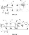
- Figures 5A and 5B illustrate the use of a soft-start circuit 350 to inject a voltage to reverse bias the diodes of the converter 320 to allow control of the commutation of current despite a DC network fault.
- Figure 5C illustrates the commutation of the converter 320 into a crow-bar configuration to reduce the fault current supplied to the DC network 330 following the fault.
- FIG 5A illustrates the previously described electrical power system 300 but with a soft-start circuit 350 also shown connected on the DC-side of the converter 320.
- the soft-start circuit which is well-known and widely used in electrical power systems, comprises a resistor 351 with a bypass switch 352 connected across its terminals.
- the bypass switch 352 can take any suitable form.
- the switch 352 comprises one or more semiconductor switching components, for example transistors or silicon controlled rectifiers (SCRs).
- the DC network 330 When the converter 320 is first energised, during which time the DC filter capacitor 328 is initially charged, the DC network 330 will tend to supply a large and damaging inrush current.
- the resistor 351 of the soft-start circuit 350 acts to limit this current to prevent damage.
- stable operation eg. , when the DC filter capacitor 328 is charged
- the resistor 351 is shorted out by closing the bypass switch 352. This prevents the resistor 351 negatively affecting operation of the converter 320. (If not shorted out the resistor 351 would e.g. , cause the DC output voltage to adversely change with load current and also create additional energy losses).
- the resistor 351 is reintroduced to the circuit (by controlling the opening the switch 352) in the event of a fault in the DC network 330. This is illustrated in Figure 5B . Reintroducing the resistor 351 and its resistance to the fault current path decouples the DC filter capacitor 328 from the fault, directing a proportion of the fault current to flow into the capacitor 328 thus allowing it to develop a direct voltage, shown in Figure 5B , capable of suitably biasing the converter diodes.
- the converter 320 can commutate current between the branches of the phase legs 321a-c and thus remove current from the DC fault. This is illustrated in Figure 5C .
- the controller 340 opens the bypass switch 352 to introduce the resistor 351 to the circuit to reverse bias the converter diodes.
- the controller 340 then controls the switching of the transistors to commutate the current so as to enter the crow-bar configuration. In the crow-bar configuration the current from the generator 310 cannot reach the DC network 320 and is instead contained within the generator 310 and converter 320.
- Figure 5C illustrates a crow-bar configuration in which current is conducted through the lower set of transistor-diode pairs (i.e., those labelled 4, 6 and 2) such that current is contained in the lower half of the converter bridge.
- a crow-bar configuration in which current is conducted through the upper set of transistor-diode pairs (i.e., those labelled 1, 3 and 5) could be used, or indeed the controller may switch the converter 320 between these two configurations.
- the resistor 351 of the soft-start circuit 345 It is generally undesirable for the resistor 351 of the soft-start circuit 345 to be connected within the DC fault path for prolonged periods, as the resistor 351 will dissipate a large amount of heat and may be damaged unless adequate heat sinking is provided.
- the injection of the resistor 351 for short periods to assist in the commutation of the converter 320 should generally be acceptable.
- the resistor 351 need only be switched into the circuit for long enough to affect a new system operating state, for example by opening or closing one or more circuit breakers (eg. , DC contactors) in the DC network to isolate the fault. Operating the circuit breakers at low or zero fault current is desirable as it may, for example, alleviate problems with contactor arcing.
- bypass switch 352 of the soft-start circuit 350 takes the form of a semiconductor switching component (e.g. , a transistor) the injection of the voltage to bias the diodes of the converter 320 may be performed without the use of the resistor 351. Specifically, operating the semiconductor switching component 352 for short periods of time in its linear operating region, with a current level within its safe thermal limits, will develop a higher voltage to produce the diode commuting voltage.
- a semiconductor switching component e.g. , a transistor
- the resistor 351 and/or semiconductor switching component 352 used to inject the voltage may instead form part of another arrangement.
- one or both components 351, 352 may be part of an auxiliary circuit dedicated to providing a biasing voltage following a DC network fault.
- Using the soft-start circuit 350 may be considered particularly convenient because it allows the biasing function to be achieved without the addition of system components, since many systems already include a soft-start circuit 350.
- the use of another (e.g., dedicated) circuit may allow for the selection of components with parameters specifically selected for the voltage injection function (eg. , a particular resistance value which balances the need to provide a high enough voltage but which does not generate excessive heat may be selected).
- Figures 6A to 6C illustrate another embodiment of the invention by which a diode biasing voltage may be injected in response to a DC network fault. It is noted that Figures 6A-C are a simplified view of the system 300 and the electrical machine 310 is not shown.
- an auxiliary voltage source 360 is connected between the DC side of the converter 320 and the DC network 330.
- the auxiliary voltage source 360 comprises a capacitor 361 connected across the terminals of a low voltage bridge 362 (a full-bridge or half-bridge structure may be used, for example) which includes a number of transistors. The transistors can be switched to either isolate or connect the capacitor 361 to the DC side of the converter 320.
- Figure 6B illustrates the normal (i.e., un-faulted) operation of the system 300.
- the transistors of the low voltage bridge 362 are switched so as to apply a voltage to charge the capacitor 361 and to also provide a bypass path so that the capacitor is not connected with the DC network 330 and converter 320.
- the controller 340 controls the switching of the transistors of the bridge 362 so as to connect the capacitor 361 between the DC side of the converter 320 and the DC network 330. This is shown in Figure 6C .
- the inserted capacitor 361 which in this example is charged by the fault current to develop an increased voltage, provides the desired biasing voltage to the converter diodes.
- voltage sources 350, 360 described with reference to Figures 5A-C and 6A-C are only examples and that other ways of providing the desired voltage will occur to those skilled in the art.
- any suitable circuit arrangement comprising one or more resistors, capacitors, inductors or semiconductor components capable of being switched into and out of DC path may be used.
- the left-hand graph of Figure 7 illustrates the 3-phase AC-side current produced by a 3-phase electrical generator 310.
- the three phases are sinusoidal and offset from each other by 120 degrees.
- One 60 degree interval of one of the three phases (phase A) is highlighted within the dashed box.
- the right-hand graph of Figure 7 illustrates the corresponding fault current delivered to the DC network 330 when the converter 320 operates as an uncontrolled diode rectifier, i.e., without utilising the invention described herein.
- the same 60 degree interval is highlighted in the right-hand graph.
- Figure 8 illustrates ways in which the current which is supplied to the faulted DC electrical network may be controlled.
- the top-left waveform of Figure 8 (labelled "No PWM") is the fault current waveform in the absence of any control (i.e., it corresponds to the right-hand graph of Figure 7 in which the invention is not utilised).
- the transistors of the converter 320 are switched into the crow-bar configuration shown in Figure 5C . This results in zero current being supplied to the DC network. Supplying zero current to the faulted DC network may be desirable in some instances, for example where circuit breaking components such as DC contactors are to be opened or closed to isolate faults.
- the controller 340 may repeatedly switch the converter transistors between the crow-bar configuration and a rectifier configuration in which the fault current is supplied to the DC network. In this way the time-averaged current supplied to the DC network will be less than full fault current level because the time spent in the crow-bar configuration will pull the average current down.
- the average current and the current waveform will depend on the modulation of the PWM signal used to switch the transistors.
- the latter is illustrated in the second and third left-hand waveforms of Figure 8 (labelled “low frequency PWM” and "high frequency PWM”).
- the PWM control parameters may be selected and varied according the desired current level and waveform.
- the current output by the converter 320 can be passed through an existing or dedicated filter 370 (eg. , a low-pass DC filter) to smooth the current waveform supplied to the DC network 330.
- an existing or dedicated filter 370 eg. , a low-pass DC filter
- the DC filter may be tuned according to the downstream requirements of the DC network.
- the unfiltered waveforms are illustrated on the left-hand side of Figure 8 , under the heading "Unfiltered”.
- An exemplary filtered waveform is shown on the right-hand side under the heading "Filtered”.
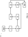
- Figure 9 is a flow diagram illustrating a method 10 of controlling an electrical power system 300.
- the method 10 may be performed by a control system which is or includes the controller 340.
- the controller 340 may, for example, be an EEC 117 or one or more functional modules of an EEC 117.
- the electrical power system 300 is operating in a normal condition.
- the rotor of the electrical machine 310 is being driven to rotate by a shaft, for example a spool of a gas turbine engine, and the machine 310 is generating AC electrical power.
- the generated AC electrical power is output from the electrical machine to an AC to DC power electronics converter 320.
- the electrical machine 310 may be a variable speed machine driven to rotate at or at a speed related to the speed of the engine drive shaft, such that the frequency and voltage of the output AC varies.
- the AC to DC converter 320 rectifies the AC to DC and outputs the DC to supply the DC electrical network 330 with DC electrical power.
- the controller 340 controls the switching of the transistors of the phase legs of the converter to commutate current and affect rectification.
- the controller 340 may supply PWM signals to the transistors in an appropriate order and with appropriate switching frequency and duty cycle to supply the desired level of DC to the network 330.
- the controller 340 determines a condition to the effect that there is a fault in the DC electrical network 330.
- the determination of a fault may occur in any number of different ways, and the precise details are beyond the scope of the present disclosure.
- voltage and current levels are measured at the loads and at a various other positions about the network 330, and faults are recognised by the controller 340 based on changes in the measured current and/or voltage levels.
- fault detection may take place locally ( eg. , at a controller local to a faulted load) and a fault report may then be communicated to the controller 340.
- Various other ways of determining faults are known and will occur to those skilled in the art.
- the controller 340 controls a voltage source 350, 360 to inject a voltage to bias the diodes of the converter 320.
- the fault in the DC network 330 will have caused the DC-side voltage to collapse, likely to a level below that required to reverse bias the converter diodes to allow commutation of the current between the branches of the converter phase legs.
- the controller 340 therefore controls a voltage source 350, 360 to inject a voltage sufficient to appropriately bias the diodes.
- the voltage source 350, 360 can take any suitable form which allows an appropriate voltage to be controllably injected from the DC side of the converter 320.
- the voltage source takes the form of a dedicated auxiliary circuit 360 whose specific purpose is to selectively inject voltage from the DC side of the converter 320 in case of a fault.
- an existing circuit for example a soft-start circuit 350, may be leveraged to inject the voltage so that further components are not required to support the function.
- Various examples of voltage sources have been described above with reference to Figures 5A-5C and 6A-6C .
- the controller 340 controls switching of the transistors of the converter 320 to control a level of current supplied to the DC electrical network. In particular, with the ability to commutate the current restored, the controller 340 can control the converter 320 to reduce the level of current supplied to the DC network 330 to a level below the full fault current which would otherwise be supplied.
- the controller 340 may control the converter 320 to reduce the current level to zero, by switching to and remaining in the crow-bar configuration. In other embodiments the controller 340 may control the converter to reduce the current level to a level between zero and the full fault current, by switching between the crow-bar configuration and the rectifier configuration. In this case the current level and waveform can be controlled by controlling PWM control parameters, for example the frequency and duty cycle of the PWM signals.
- the DC output may also be passed through a filter to smooth the waveform to better approximate a true DC signal.
- the diode rectifier mode illustrated in Figure 5C may be replaced by a so-called 'synchronous rectification mode' which makes use of the bi-directional current carrying capability of the MOSFETs.
- the diodes whether separate diodes or the inherent body diodes of the MOSFETs do not carry current. Instead, the bi-directional MOSFETs carry current in their reverse directions in place of the diodes.
- the controller 340 controls the state of one or more circuit breaking components (e.g., contactors) in the DC network 330.
- the controller 340 may open a DC contactor to isolate a fault from the remainder of the DC network 330. If it is possible to completely isolate the fault, it may be possible to return to the normal operating condition of the system, with full and normal control of the AC to DC converter 320. In other cases the system 300 may remain in the condition of step 15 in which the current level is controlled but a fault still remains. In some instances, having safely controlled the current level in the DC network and taken appropriate action, the generator 310 may be disconnected from the drive shaft or may be isolated from the remainder of the electrical power system 300.
- one or more circuit breaking components e.g., contactors
Landscapes
- Engineering & Computer Science (AREA)
- Power Engineering (AREA)
- Aviation & Aerospace Engineering (AREA)
- Chemical & Material Sciences (AREA)
- Combustion & Propulsion (AREA)
- Mechanical Engineering (AREA)
- General Engineering & Computer Science (AREA)
- Rectifiers (AREA)
Applications Claiming Priority (1)
| Application Number | Priority Date | Filing Date | Title |
|---|---|---|---|
| GBGB2115015.6A GB202115015D0 (en) | 2021-10-20 | 2021-10-20 | Electrical power system converter control |
Publications (1)
| Publication Number | Publication Date |
|---|---|
| EP4170881A1 true EP4170881A1 (de) | 2023-04-26 |
Family
ID=78718507
Family Applications (1)
| Application Number | Title | Priority Date | Filing Date |
|---|---|---|---|
| EP22196867.0A Pending EP4170881A1 (de) | 2021-10-20 | 2022-09-21 | Steuerung eines elektrischen stromsystemwandlers |
Country Status (3)
| Country | Link |
|---|---|
| US (1) | US20230123533A1 (de) |
| EP (1) | EP4170881A1 (de) |
| GB (1) | GB202115015D0 (de) |
Cited By (2)
| Publication number | Priority date | Publication date | Assignee | Title |
|---|---|---|---|---|
| EP4300808A1 (de) | 2022-06-27 | 2024-01-03 | Rolls-Royce plc | Flugzeugantriebs- und -antriebssysteme mit elektrischen permanentmagnetmaschinen |
| EP4300806A1 (de) | 2022-06-27 | 2024-01-03 | Rolls-Royce plc | Flugzeugantriebs- und -antriebssysteme mit elektrischen permanentmagnetmaschinen |
Citations (4)
| Publication number | Priority date | Publication date | Assignee | Title |
|---|---|---|---|---|
| DE19548612A1 (de) * | 1995-12-23 | 1997-06-26 | Bosch Gmbh Robert | Elektronischer Schalter |
| EP0867998A1 (de) * | 1997-03-24 | 1998-09-30 | Asea Brown Boveri Ab | Anlage zur elektrischen Leistungsübertragung |
| EP2858231A1 (de) * | 2013-10-07 | 2015-04-08 | Alstom Technology Ltd | Spannungsquellenumrichter |
| EP3780367A1 (de) * | 2019-08-12 | 2021-02-17 | EldoLAB Holding B.V. | Neutrallose stromversorgung mit abwärtswandler |
-
2021
- 2021-10-20 GB GBGB2115015.6A patent/GB202115015D0/en not_active Ceased
-
2022
- 2022-09-21 EP EP22196867.0A patent/EP4170881A1/de active Pending
- 2022-09-22 US US17/950,445 patent/US20230123533A1/en active Pending
Patent Citations (4)
| Publication number | Priority date | Publication date | Assignee | Title |
|---|---|---|---|---|
| DE19548612A1 (de) * | 1995-12-23 | 1997-06-26 | Bosch Gmbh Robert | Elektronischer Schalter |
| EP0867998A1 (de) * | 1997-03-24 | 1998-09-30 | Asea Brown Boveri Ab | Anlage zur elektrischen Leistungsübertragung |
| EP2858231A1 (de) * | 2013-10-07 | 2015-04-08 | Alstom Technology Ltd | Spannungsquellenumrichter |
| EP3780367A1 (de) * | 2019-08-12 | 2021-02-17 | EldoLAB Holding B.V. | Neutrallose stromversorgung mit abwärtswandler |
Cited By (2)
| Publication number | Priority date | Publication date | Assignee | Title |
|---|---|---|---|---|
| EP4300808A1 (de) | 2022-06-27 | 2024-01-03 | Rolls-Royce plc | Flugzeugantriebs- und -antriebssysteme mit elektrischen permanentmagnetmaschinen |
| EP4300806A1 (de) | 2022-06-27 | 2024-01-03 | Rolls-Royce plc | Flugzeugantriebs- und -antriebssysteme mit elektrischen permanentmagnetmaschinen |
Also Published As
| Publication number | Publication date |
|---|---|
| GB202115015D0 (en) | 2021-12-01 |
| US20230123533A1 (en) | 2023-04-20 |
Similar Documents
| Publication | Publication Date | Title |
|---|---|---|
| EP4170881A1 (de) | Steuerung eines elektrischen stromsystemwandlers | |
| EP2709229B1 (de) | Stromverteilungssysteme | |
| US5325042A (en) | Turbine engine start system with improved starting characteristics | |
| US9745943B2 (en) | Control and power supply system for helicopter turbine engines | |
| KR100705864B1 (ko) | 터빈 작동 방법, 터빈 시동 방법 및 전력 회로 | |
| EP4170893A1 (de) | Steuerung eines elektrischen stromsystemwandlers | |
| US6169390B1 (en) | Flywheel-microturbine system | |
| US7939959B2 (en) | Wind turbine with parallel converters utilizing a plurality of isolated transformer windings | |
| US6631080B2 (en) | Systems and methods for boosting DC link voltage in turbine generators | |
| CN111954622B (zh) | 具有可重构电力网络的多转子飞行器推进系统 | |
| US9954393B2 (en) | Power distribution systems | |
| CN106208071B (zh) | 混合式ac及dc分配系统和使用方法 | |
| WO2015183353A1 (en) | Electric power generation and distribution for islanded or weakly-connected systems | |
| CN112532128A (zh) | 一种航空大功率复合无刷起动发电系统及其控制方法 | |
| CN102420560B (zh) | 变频交流起动发电系统励磁结构及交、直流励磁控制方法 | |
| EP2045910B1 (de) | Starter/Generatorsystem mit Steuerung zur Adressierung eines Spannungsanstiegs | |
| US20240063729A1 (en) | Electrical Power System Converter Control | |
| US20230373319A1 (en) | Power electronics converter | |
| RU2422977C1 (ru) | Способ плавного пуска электродвигателя переменного тока | |
| US20240084710A1 (en) | Aircraft power and propulsion systems comprising permanent magnet electrical machines | |
| EP4300806A1 (de) | Flugzeugantriebs- und -antriebssysteme mit elektrischen permanentmagnetmaschinen | |
| Jiao et al. | Topology and Control Method of Aircraft Two-Stage HVDC Integrated Starter-Generator System | |
| US11873109B2 (en) | Electrical power system | |
| CN105515476B (zh) | 提高无刷电励磁轴带发电系统短路过载能力的装置和方法 | |
| Zhou et al. | Dual voltage DC generator for compact light-weight ship electrical systems |
Legal Events
| Date | Code | Title | Description |
|---|---|---|---|
| PUAI | Public reference made under article 153(3) epc to a published international application that has entered the european phase |
Free format text: ORIGINAL CODE: 0009012 |
|
| STAA | Information on the status of an ep patent application or granted ep patent |
Free format text: STATUS: THE APPLICATION HAS BEEN PUBLISHED |
|
| AK | Designated contracting states |
Kind code of ref document: A1 Designated state(s): AL AT BE BG CH CY CZ DE DK EE ES FI FR GB GR HR HU IE IS IT LI LT LU LV MC MK MT NL NO PL PT RO RS SE SI SK SM TR |
|
| STAA | Information on the status of an ep patent application or granted ep patent |
Free format text: STATUS: REQUEST FOR EXAMINATION WAS MADE |
|
| 17P | Request for examination filed |
Effective date: 20230714 |
|
| RBV | Designated contracting states (corrected) |
Designated state(s): AL AT BE BG CH CY CZ DE DK EE ES FI FR GB GR HR HU IE IS IT LI LT LU LV MC MK MT NL NO PL PT RO RS SE SI SK SM TR |