EP4170848A1 - Procédé d'amortissement des vibrations basse fréquence dans un réseau d'alimentation électrique - Google Patents
Procédé d'amortissement des vibrations basse fréquence dans un réseau d'alimentation électrique Download PDFInfo
- Publication number
- EP4170848A1 EP4170848A1 EP21203591.9A EP21203591A EP4170848A1 EP 4170848 A1 EP4170848 A1 EP 4170848A1 EP 21203591 A EP21203591 A EP 21203591A EP 4170848 A1 EP4170848 A1 EP 4170848A1
- Authority
- EP
- European Patent Office
- Prior art keywords
- signal
- frequency
- damping
- target
- oscillation
- Prior art date
- Legal status (The legal status is an assumption and is not a legal conclusion. Google has not performed a legal analysis and makes no representation as to the accuracy of the status listed.)
- Pending
Links
- 238000013016 damping Methods 0.000 title claims abstract description 204
- 238000000034 method Methods 0.000 title claims abstract description 39
- 230000010355 oscillation Effects 0.000 claims abstract description 170
- 230000036961 partial effect Effects 0.000 claims abstract description 101
- 238000004458 analytical method Methods 0.000 claims abstract description 64
- 230000001419 dependent effect Effects 0.000 claims abstract description 22
- 238000002347 injection Methods 0.000 claims abstract description 10
- 239000007924 injection Substances 0.000 claims abstract description 10
- 238000005070 sampling Methods 0.000 claims description 27
- 230000004913 activation Effects 0.000 claims description 19
- 238000009434 installation Methods 0.000 claims description 15
- 238000001914 filtration Methods 0.000 claims description 11
- 230000009849 deactivation Effects 0.000 claims description 10
- 238000006243 chemical reaction Methods 0.000 claims description 9
- 238000004891 communication Methods 0.000 claims description 9
- 238000001514 detection method Methods 0.000 claims description 8
- 238000011156 evaluation Methods 0.000 claims description 4
- 230000003213 activating effect Effects 0.000 claims description 2
- 230000008859 change Effects 0.000 description 9
- 238000005259 measurement Methods 0.000 description 8
- 239000000243 solution Substances 0.000 description 8
- 230000008569 process Effects 0.000 description 5
- 238000012545 processing Methods 0.000 description 5
- 230000005540 biological transmission Effects 0.000 description 4
- 238000012937 correction Methods 0.000 description 4
- 230000010363 phase shift Effects 0.000 description 4
- 238000007493 shaping process Methods 0.000 description 4
- 230000003595 spectral effect Effects 0.000 description 4
- 230000003321 amplification Effects 0.000 description 3
- 230000008901 benefit Effects 0.000 description 3
- 230000000694 effects Effects 0.000 description 3
- 238000003199 nucleic acid amplification method Methods 0.000 description 3
- 238000001228 spectrum Methods 0.000 description 3
- 230000009466 transformation Effects 0.000 description 3
- 230000006978 adaptation Effects 0.000 description 2
- 230000003044 adaptive effect Effects 0.000 description 2
- 230000033228 biological regulation Effects 0.000 description 2
- 238000010276 construction Methods 0.000 description 2
- 230000003247 decreasing effect Effects 0.000 description 2
- 238000010586 diagram Methods 0.000 description 2
- 230000005284 excitation Effects 0.000 description 2
- 230000002238 attenuated effect Effects 0.000 description 1
- 230000015572 biosynthetic process Effects 0.000 description 1
- 238000004140 cleaning Methods 0.000 description 1
- 239000012141 concentrate Substances 0.000 description 1
- 230000001276 controlling effect Effects 0.000 description 1
- 230000006866 deterioration Effects 0.000 description 1
- 230000005520 electrodynamics Effects 0.000 description 1
- 230000001747 exhibiting effect Effects 0.000 description 1
- 230000006872 improvement Effects 0.000 description 1
- 230000000670 limiting effect Effects 0.000 description 1
- 230000009467 reduction Effects 0.000 description 1
- 230000002829 reductive effect Effects 0.000 description 1
- 230000001105 regulatory effect Effects 0.000 description 1
- 230000000717 retained effect Effects 0.000 description 1
- 230000008054 signal transmission Effects 0.000 description 1
- 230000001629 suppression Effects 0.000 description 1
- 230000001360 synchronised effect Effects 0.000 description 1
- 238000012360 testing method Methods 0.000 description 1
- 238000000844 transformation Methods 0.000 description 1
- 238000011144 upstream manufacturing Methods 0.000 description 1
Images


Classifications
-
- H—ELECTRICITY
- H02—GENERATION; CONVERSION OR DISTRIBUTION OF ELECTRIC POWER
- H02J—CIRCUIT ARRANGEMENTS OR SYSTEMS FOR SUPPLYING OR DISTRIBUTING ELECTRIC POWER; SYSTEMS FOR STORING ELECTRIC ENERGY
- H02J3/00—Circuit arrangements for ac mains or ac distribution networks
- H02J3/24—Arrangements for preventing or reducing oscillations of power in networks
- H02J3/241—The oscillation concerning frequency
-
- H—ELECTRICITY
- H02—GENERATION; CONVERSION OR DISTRIBUTION OF ELECTRIC POWER
- H02J—CIRCUIT ARRANGEMENTS OR SYSTEMS FOR SUPPLYING OR DISTRIBUTING ELECTRIC POWER; SYSTEMS FOR STORING ELECTRIC ENERGY
- H02J3/00—Circuit arrangements for ac mains or ac distribution networks
- H02J3/38—Arrangements for parallely feeding a single network by two or more generators, converters or transformers
- H02J3/381—Dispersed generators
-
- F—MECHANICAL ENGINEERING; LIGHTING; HEATING; WEAPONS; BLASTING
- F03—MACHINES OR ENGINES FOR LIQUIDS; WIND, SPRING, OR WEIGHT MOTORS; PRODUCING MECHANICAL POWER OR A REACTIVE PROPULSIVE THRUST, NOT OTHERWISE PROVIDED FOR
- F03D—WIND MOTORS
- F03D7/00—Controlling wind motors
- F03D7/02—Controlling wind motors the wind motors having rotation axis substantially parallel to the air flow entering the rotor
- F03D7/028—Controlling wind motors the wind motors having rotation axis substantially parallel to the air flow entering the rotor controlling wind motor output power
- F03D7/0284—Controlling wind motors the wind motors having rotation axis substantially parallel to the air flow entering the rotor controlling wind motor output power in relation to the state of the electric grid
-
- H—ELECTRICITY
- H02—GENERATION; CONVERSION OR DISTRIBUTION OF ELECTRIC POWER
- H02J—CIRCUIT ARRANGEMENTS OR SYSTEMS FOR SUPPLYING OR DISTRIBUTING ELECTRIC POWER; SYSTEMS FOR STORING ELECTRIC ENERGY
- H02J2300/00—Systems for supplying or distributing electric power characterised by decentralized, dispersed, or local generation
- H02J2300/20—The dispersed energy generation being of renewable origin
- H02J2300/28—The renewable source being wind energy
-
- Y—GENERAL TAGGING OF NEW TECHNOLOGICAL DEVELOPMENTS; GENERAL TAGGING OF CROSS-SECTIONAL TECHNOLOGIES SPANNING OVER SEVERAL SECTIONS OF THE IPC; TECHNICAL SUBJECTS COVERED BY FORMER USPC CROSS-REFERENCE ART COLLECTIONS [XRACs] AND DIGESTS
- Y02—TECHNOLOGIES OR APPLICATIONS FOR MITIGATION OR ADAPTATION AGAINST CLIMATE CHANGE
- Y02E—REDUCTION OF GREENHOUSE GAS [GHG] EMISSIONS, RELATED TO ENERGY GENERATION, TRANSMISSION OR DISTRIBUTION
- Y02E10/00—Energy generation through renewable energy sources
- Y02E10/70—Wind energy
- Y02E10/76—Power conversion electric or electronic aspects
Definitions
- the present invention relates to a method for damping low-frequency oscillations in an electrical supply network by means of a feed device that feeds into the electrical supply network, in particular by means of a wind turbine.
- the present invention relates to a corresponding wind energy installation.
- Wind energy installations are known, they feed electrical power into an electrical supply network and are often also used to support the electrical supply network.
- it is known to feed in reactive power as a function of the mains voltage of the electrical supply network.
- a deviation of the mains voltage from a nominal mains voltage is considered and depending on this reactive power is fed in, which can be implemented by changing the phase angle of the current being fed in.
- Such a procedure is from the document U.S. 6,965,174 known.
- subsynchronous oscillations can occur in the electrical supply network. These can become noticeable as fluctuations in the voltage amplitudes. Such fluctuations can have frequencies below the nominal grid frequency, especially in the range of a few Hertz or even with frequencies below 1 Hz cause electrical oscillations in the network that cause other participants to react. These are essentially slow oscillations in the range of 0.1 Hz-1.5 Hz that are considered here. These are particularly inter-area vibrations, which are correspondingly slow, i.e. mostly below 1 Hz, rarely up to 1.5 Hz, or in one exception can reach 1.8 Hz.
- Such a detection has been proposed for checking for the presence of at least one subsynchronous oscillation over a frequency spectrum that can range over several orders of magnitude.
- it is possible to detect a subsynchronous oscillation with such a method but the method can have disadvantages for an implementation that also provides for damping of such subsynchronous oscillations.
- a higher quality of the detection is often required for the detection in order to provide an attenuation based thereon, but without such a large frequency spectrum having to be covered. It is particularly important that not every frequency in which a subsynchronous oscillation can occur must also be disruptive. Instead, damping of subsynchronous vibrations can often only be necessary in a narrowly specified frequency range.
- the damping of subsynchronous oscillations can be carried out by injecting reactive power.
- a damping reactive power feed can possibly collide with an above-mentioned voltage-dependent reactive power feed. It is therefore possible for a voltage-dependent reactive power feed to work against a reactive power feed that is intended to dampen subsynchronous oscillations.
- the present invention is therefore based on the object of addressing at least one of the problems mentioned above.
- a solution is to be proposed in which subsynchronous oscillations in a relevant frequency range are recognized and dampened, in particular with as little influence as possible on other grid-supporting feeds.
- an alternative solution to previously known solutions should be proposed.
- a feed device that feeds into the electrical supply network.
- a feed device can in particular be a wind energy plant.
- other decentralized feed-in devices can also be considered, e.g. feed from an energy store, from which a frequency converter is used to feed. Feeding in from other energy sources is also possible.
- the method is not suitable for directly coupled synchronous generators.
- the infeed devices that can be used here are therefore, in particular, converter-controlled infeed devices.
- so-called full converter concepts are proposed in which the entire power fed in is routed through a converter arrangement, so that the entire power fed in can be controlled by the converter arrangement in terms of amplitude, frequency and phase.
- An electrical supply network is assumed that has a network frequency, in particular the usual 50 Hz or 60 Hz. According to one step, it is proposed to record a network signal that has the low-frequency oscillations. In particular, a mains voltage is detected here. Of course, it can also happen that it turns out that there are no low-frequency vibrations at all. However, this network signal potentially exhibits the low-frequency oscillations, or at least one.
- Each sub-frequency range has a low, high, and middle range frequency. If, for example, vibrations to be damped are to be expected in a frequency range of 1-5Hz, a partial frequency range can range from 1Hz to 3Hz and thus have 1Hz, 2Hz and 3Hz as the lower, middle and upper frequency range. Another partial frequency range can range from 2Hz to 4Hz and thus have 2Hz, 3Hz and 4Hz as the lower, middle and upper frequency range. A third sub-frequency range can range from 3Hz to 5Hz and have 3Hz, 4Hz and 5Hz as the lower, middle and upper range frequencies accordingly.
- the center range frequency can be chosen as the arithmetic mean of the low and high range frequencies.
- a low-frequency vibration to be damped as a target vibration, depending on the frequency analyzes of all partial frequency ranges. It was particularly recognized here that a number of vibrations with different vibration frequencies can be identified, but it is not necessarily expedient and/or possible to dampen all of these vibration frequencies.
- a proposed embodiment is to select a possible target oscillation only from oscillations with oscillation frequencies that are also to be damped.
- a frequency range in which vibrations are to be damped if they occur, is smaller than the frequency range examined overall.
- the overall frequency range can already be defined in such a way that it goes beyond such a frequency range in which oscillations are to be damped.
- relevant frequencies can no longer be optimally identified at the edge of the overall frequency range, in particular at the edge of a partial frequency range.
- Vibration as a target vibration can already include identifying its frequency. However, this can still mean an inaccurate identification of the frequency of this target vibration. To this end, it is then proposed to record the target vibration according to frequency and amplitude as precisely as possible. Optionally, a phase, i.e. the phase position of the target oscillation, can also be recorded. This can be helpful for the damping to be carried out, but is not absolutely necessary, as will be seen below.
- a target damping signal as a function of the target vibration detected according to frequency and amplitude and possibly also phase, in order to dampen the detected target vibration.
- a desired damping signal itself has the frequency of the target oscillation.
- Setting a phase of the desired damping signal is also advantageous in order to then generate a corresponding damping signal according to the desired damping signal, which also damps the target oscillation and does not excite it if the phase position is incorrect.
- a phase position of the desired damping signal and thus also of the damping signal does not necessarily have to be set as a direct function of a phase of the detected target oscillation.
- the detected target oscillation or a signal derived from it can otherwise influence the phase position of the damping setpoint signal and thus the damping signal.
- one option is to record the phase of the target vibration and to determine the phase of the damping setpoint signal based on this.
- such a desired damping signal does not necessarily have to be a sinusoidal signal, but one variant is that the desired damping signal is sinusoidal.
- the desired feed-in signal is therefore a specification for a feed-in signal, which can in particular be reactive power to be fed in, but can also be or contain active power.
- the injection signal is supposed to implement the damping, but there can be other tasks for the injection signal, e.g. to support a voltage. These additional tasks, or just one additional task, are specified by the base target signal.
- the intended damping and the other tasks are therefore taken into account together in the desired feed signal and then in the feed signal.
- the desired feed signal is then composed in particular of the desired damping signal and the basic desired signal.
- the feed signal is then made up of a base signal and the damping signal. are for each target signals provided, so the feed target signal for the feed signal, the base target signal for the base signal and the attenuation target signal for the attenuation signal.
- the feed signal is generated and fed in as a function of the desired feed signal. This can be done with the help of a converter arrangement.
- the damping signal can be a reactive power or a reactive current.
- the feeding in of a reactive power or a reactive current can already be provided as a base signal.
- a voltage-dependent reactive power feed is already implemented.
- Such a voltage-dependent reactive power feed essentially supplies a constant reactive power or a constant reactive current when the mains voltage is essentially constant.
- such a voltage-dependent reactive power feed basically reacts to low-frequency oscillations that are superimposed on the base voltage signal, with a reaction that can even lead to a deterioration, in particular excitation of the oscillation.
- the desired damping signal is recorded and switched to the basic desired signal.
- the amplitude of the target oscillation may be small compared to the amplitude of the mains voltage, so the mains voltage may have a small amount of variation, but the derived damping target signal may have a significant amplitude, which may be of the order of the base target signal or greater. Of course, it can also be lower, which also depends on how large such a voltage-dependent reactive power is in each case, to stay with this example.
- this superimposition creates a desired feed signal or feed signal, or it is proposed to generate and feed the feed signal as a function of the desired feed signal.
- a feed signal can then be generated and controlled, which contains the damping signal and also an already existing base signal.
- a damping reactive power signal or reactive current signal on a voltage-dependent Reactive power feed or reactive current feed can be coordinated. This joint consideration prevents the damping signal and the voltage-dependent generated base signal from working against each other.
- the desired damping signal describes a reactive power to be fed in and, in particular, that the basic desired signal is specified by reactive power control as a desired signal for a reactive power to be fed in.
- the reactive power control can, for example, implement a permanently specified reactive power target value, but grid-voltage-dependent reactive power feed-in can also be considered.
- the feed-in signal is then also made up of the reactive power according to the desired damping signal and the reactive power according to the basic desired signal.
- the damping of the low-frequency oscillation takes place by means of a corresponding reactive power signal.
- a voltage oscillation in particular can be counteracted.
- the active power that is fed in is varied, and as a result, mechanical stresses on the wind energy plant due to the varying provision of active power are avoided.
- an oscillating change in active power can lead to correspondingly oscillating mechanical loads on the generator, which can also be transferred to other parts of the wind energy installation. For example, the tower can vibrate, which is avoided in this way.
- a core controller is provided to generate the desired feed signal, which outputs a controller output signal as a function of the basic desired signal and the fed-in signal, and that the desired feed signal is determined as a function of the controller output signal.
- the desired damping signal or part of it be superimposed on the basic desired signal and thus be taken into account by the core controller.
- the desired damping signal or a part thereof is applied to the controller output signal and thereby influences the desired feed signal.
- a core controller is therefore provided, which can also be referred to synonymously as an inner controller or inner control loop.
- This core controller emits a controller output signal as a function of the basic setpoint signal and the feed signal that is fed in.
- a setpoint/actual value comparison is formed between the basic setpoint signal and the feed-in signal that is fed in, and this setpoint/actual value comparison, i.e. the resulting control error, thus forms the input signal of the core controller.
- the controller output signal then forms the basis for the feed setpoint signal.
- the feed setpoint signal corresponds to the controller output signal.
- the desired feed signal is thus the sum of the controller output signal and the desired damping signal or the part thereof that is superimposed.
- the desired feed signal results here exclusively from the controller output signal and the added damping desired signal. Since the desired damping signal can be a sinusoidal signal in particular, it can of course also be subtracted depending on the phase position.
- the base setpoint signal, the setpoint attenuation signal and, correspondingly, also the resulting setpoint feed signal is a setpoint signal for a reactive power in each case.
- the base target signal can be a reactive power target signal that a voltage-dependent reactive power controller has output or specified.
- This basic setpoint signal which would be specified by such a voltage-dependent reactive power controller, especially when vibration damping is deactivated, should be implemented as well as possible with the help of the core controller.
- the setpoint/actual value comparison is made between the basic setpoint signal and the feed-in signal, i.e. the reactive power actually fed in, and leads to a control error.
- the core controller issues the controller output signal.
- the controller output signal is then itself a reactive power reference value.
- a core controller which can be the innermost controller of a corresponding controller cascade, regulates in particular deviations that occur due to the converting converter or are caused by the influence of lines and/or transformers.
- transmission lines from a wind turbine to a grid connection point, especially if the wind turbine is part of a wind farm, can be relevant here.
- this core controller modifies the basic setpoint signal in such a way that it compensates for changes caused by conversion by converters and the influence of cables and transformers.
- this core controller modifies the basic setpoint signal in such a way that it compensates for changes caused by conversion by converters and the influence of cables and transformers.
- the desired damping signal is superimposed on the basic desired signal.
- the result is compared with the actual value of the feed signal and the resulting control error is converted by the core controller into a modified target signal, i.e. into the controller output signal.
- the desired damping signal can basically be switched on in a simple manner.
- the desired damping signal can be in the form of a sinusoidal signal in particular, and this means that the core controller, which is essentially designed for a stationary signal without this desired damping signal, has to constantly readjust an oscillating signal. This can lead to a phase shift of this oscillating part due to the core controller, because it was not originally designed for regulating such a sinusoidal signal.
- the core controller can in particular have an integral part, since it is intended to achieve stationary accuracy for use without a superimposed sinusoidal damping signal.
- an integral part can be unfavorable for the correction of an oscillating signal, or at least not work optimally.
- the core controller can then continue to regulate a stationary accuracy for the base setpoint signal, ie basically as in the case when no damping setpoint signal is applied.
- the oscillating desired damping signal is then applied to the resulting controller output signal, which means that it does not have to pass through the core controller.
- Deviations caused by converters and the influence of lines and transformers cannot then be corrected for the damping signal, but this can be acceptable.
- Frequency and phase position are particularly important for the damping signal. Any deviations in amplitude are of less importance. A phase shift can be taken into account in other ways, particularly when generating the desired damping signal.
- a damping compensation signal dependent on the desired damping signal is applied, in particular to the basic desired signal, in order to at least partially compensate for an influence of the desired damping signal via the fed-back signal on the core controller.
- the basic idea here is to remove the damping signal from the recorded and fed-back feed signal.
- a target actual value comparison can then be carried out between the basic target value and the detected, fed-back feed signal, which results in a control error or control deviation corrected for the damping signal, so that a control error correspondingly corrected for the damping signal is input into the core controller. Due to the linear linkage when forming the control error, it is not important where exactly the compensation signal component is applied for correction, in particular whether the application is made with the appropriate sign for correction on the base setpoint, the fed-back signal, or on the control error.
- the oscillating signal superimposed on the feed signal that is actually fed in is not necessarily identical to the desired attenuation signal applied beforehand. Accordingly, a signal can be generated that corresponds approximately to the resulting oscillating partial signal superimposed on the feed signal. This is superimposed on the returned injection signal with the sign reversed, so essentially the same to compensate for the superimposed partial signal. In the ideal case, a setpoint/actual value comparison then takes place between the basic setpoint signal and the feed-in signal which has been corrected for this superimposed oscillating partial signal.
- the damping compensation signal is switched on the input side of the core controller, which emits a controller output signal as a function of the base setpoint signal and the fed-in feed signal, in particular to the base setpoint signal.
- the attenuation compensation signal is generated by filtering out a compensation signal component from the recorded feed signal.
- the compensation signal component has an oscillation frequency of the identified target oscillation and the damping compensation signal is formed as a function of the compensation signal component.
- the attenuation compensation signal can correspond to the compensation signal component.
- the filter is thus adjusted in such a way that it filters out a signal component with the oscillation frequency of the identified target oscillation. In this way it can be achieved that essentially the damping signal is filtered out as a compensation signal component, but with a changed amplitude and phase position in comparison to the desired damping signal.
- the compensation signal component filtered out in this way can be used directly as an attenuation compensation signal.
- an adjustment of the amplitude and/or the phase can also be considered if the compensation signal component is converted into the attenuation compensation signal. It is also possible to make the connection of the damping compensation signal or the further processing of the compensation signal component dependent on criteria such as an amplitude of the desired damping signal.
- a bandpass filter can be used to filter out the damping compensation signal from the detected injection signal and tuned to the oscillation frequency of the identified target oscillation.
- the bandpass filter essentially only lets through signals with the oscillation frequency of the identified target oscillation.
- the underlying idea is to remove the damping signal from the recorded and fed-back feed signal.
- At least three overlapping partial frequency ranges be provided.
- at least four, at least five or at least six partial frequency ranges are provided.
- the frequency analysis of the network signal for each sub-frequency range is better the narrower the frequency range is selected.
- the lower range frequency of each sub-frequency range defines the minimum length of time over which the signal must be recorded and evaluated here. The lower range frequency therefore limits the speed of the evaluation.
- the upper range frequency defines a minimum sampling frequency, which can also be referred to synonymously as the sampling rate, and high frequencies should also be recorded as quickly as possible.
- the lower and upper frequency range of each partial frequency range are thus in a certain contradiction and it is therefore proposed to select the partial frequency ranges as small as possible.
- the selection of smaller partial frequency ranges and thus the use of a larger number of partial frequency ranges does not necessarily have to lead to a correspondingly higher computing capacity being required.
- the computing effort can be kept correspondingly small by a good adaptation of the measurement duration and sampling frequency.
- the upper range frequency of a partial frequency range is in the range of 1.5 times to 10 times the lower range frequency of the same partial frequency range.
- the upper range frequency of a sub-frequency range is in the range of two to three times the lower range frequency of the same sub-frequency range.
- a frequency spectrum from 1 Hz to 16 Hz can already be covered with twice the value of the upper range frequency compared to the lower range frequency and with a choice of four partial frequency ranges. With a small overlap, for example, a range of 0.5 - 5Hz can be covered. It was also recognized that, in order to take into account relevant low-frequency oscillations in the electrical supply network, covering such a frequency range of, for example, 0.5-5 Hz can be sufficient.
- the respective frequency analysis uses different time sections of the detected network signal for each partial frequency range and has different sampling rates. This allows the frequency analysis to be well adjusted for each partial frequency range.
- such a time section that is as small as possible is defined by the lower range frequency of the respective partial frequency range, so that the selection of the shortest possible time segments means that they are different for each partial frequency range.
- a sampling rate that is as high as possible would be desirable.
- the sampling rate should not be selected too high.
- the number of samples per time segment is therefore preferably chosen to be the same or similar for the partial frequency ranges.
- the advantage explained does not only result if this number of samples per time section is always exactly the same.
- each partial frequency range is assigned a time segment of the network signal for evaluation, with time segments of several partial frequency ranges overlapping, and the time segment is larger the smaller the lower range frequency of the assigned partial frequency range is, and/or each partial frequency range for carrying out the frequency analysis is assigned a sampling rate that is greater the greater the upper range frequency of the partial frequency range.
- a number of samples per time section be used that is the same for different partial frequency ranges, in particular for all partial frequency ranges.
- a time segment of the network signal is therefore a section of the network signal that is analyzed in each case. It is of different length for different partial frequency ranges.
- the partial frequency ranges are evaluated as far as possible, ie also preferably, in an online calculation.
- the analysis for all partial frequency ranges also takes place in parallel or at the same time.
- the respective time excerpts are of different lengths, but appear at the same time, insofar as they are at least overlapping.
- the time sections can be implemented as sliding windows. Then the current time sections of each partial frequency range could have the same end time, which in turn is constantly renewed.
- the choice of the length of the time segment is therefore decisive.
- the length of the time segment is therefore based on the lower range frequency.
- the evaluation or calculation can be updated for the different partial frequency ranges at the same time.
- the time windows of different lengths go back different distances from such an update time, so that the end times, ie usually about the current time, are the same, but the start times are different.
- the sampling rate can be based on the size of the time section and can result in particular from the fact that a fixed number of samples per time section is specified. In addition or as an alternative, the sampling rate can also be based on the upper range frequency. After all, the sampling rate must be chosen so large that even the highest oscillation frequency still to be analyzed in the respective partial frequency range is sampled with a sufficiently high sampling rate.
- the duration of the time segment of the partial frequency range corresponds to at least half, in particular at least the entire reciprocal value of the lower range frequency.
- the duration of the time section of the partial frequency range corresponds to at least half a period. It was recognized that half the period of a signal can be sufficient to identify it.
- the duration of the time segment corresponds at most to five times the reciprocal value of the lower range frequency. It is therefore proposed to carry out the analysis over a maximum period of five times the longest period. In principle, an analysis can also take longer, but it should be noted that the result of the analysis should be available as early as possible. Choosing a time section that is too long results in an analysis time that is too long, which is avoided by setting the upper value of the time section.
- the sampling rate of a partial frequency range corresponds to at least twice, in particular at least five times, the upper range frequency. This ensures that sufficiently high sampling is performed even for signals in the upper frequency range.
- a technical lower limit is double the sampling rate of a frequency.
- the sampling rate of a partial frequency range corresponds at most to 100 times, in particular at most to 50 times, the upper range frequency.
- the sampling rate could be chosen as high as desired, but for practical reasons it was recognized that too high a sampling rate requires too much computing power.
- the sampling rate is based on the upper range frequency, the lower range frequency determines or influences the measurement duration.
- a solution is therefore proposed here in which measurements are taken for a sufficiently long time for the lower range frequency, sampling is carried out sufficiently frequently for the upper range frequency and all of this can also be evaluated in the shortest possible time.
- an oscillation with an oscillating frequency was detected in a first of the partial frequency ranges with a higher upper range frequency than at least one other partial frequency range, this oscillating frequency is taken into account as a potential aliasing frequency.
- a filtered signal of the network signal is then used for the frequency analysis of at least a second of the partial frequency ranges with a lower upper range frequency than in the case of the first partial frequency range. Signal components with the aliasing frequency are filtered out of this filtered signal.
- the partial frequency ranges can detect oscillations of different oscillation frequencies.
- a high frequency oscillation is detected in a high upper frequency sub-frequency range, it will still occur in lower upper frequency frequency sub-frequency ranges because it naturally occurs throughout the recorded mains signal.
- they may not be able to be identified in such sub-frequency ranges with a lower upper range frequency, because the frequency analysis adapted to the respective sub-frequency range, especially the sampling rate, is not designed for such frequencies.
- the frequency analysis is carried out for each partial frequency range in order to identify at least one oscillation with a first frequency.
- the frequency, amplitude and optionally the phase of the vibration identified in the first analysis step be identified by means of a signal examination adapted to the identified vibration.
- the adjusted signal analysis of the identified vibration has a higher resolution than the frequency analysis that identified the vibration in the first analysis step and/or is specifically tuned to the first frequency identified in the first analysis step.
- the analysis may only result in a vibration with a frequency of 1.2 Hz being detected. The exact frequency could not be identified.
- a higher resolution and/or targeted tuning to this first frequency of 1.2 Hz is carried out in such a more precisely delimited frequency range, that is to say in the example in the range from 1.1 Hz to 1.3 Hz.
- spectral lines to be examined can be selected and such a selection is made for the second pass depending on the result of the first examination.
- a window with a duration (window length) of 50s can be used, for which 50 points are provided.
- the length specifies the frequency resolution, in this case 1/50 Hz. Therefore, the spectral lines can be calculated with a resolution of 1/50 Hz, up to a maximum frequency that depends on the time resolution.
- the examination can therefore cover a range from DC-1Hz, with a resolution of 50 values. If, for example, 0.8Hz occurs during the first iteration, it is initially no longer possible to be more precise because the increment is fixed because no new measurements are taken. The analysis can then be improved by a further measurement, in particular parallel measurement with higher resolution.
- phase angle of the reference signal is changed by m iterations in a loop in the complete range, ie for 0 to 2 ⁇ or 0° to 360°.
- frequency of the reference signal is changed in a further loop by n iterations in the frequency range to be examined.
- the frequency range to be examined is very limited due to the vibration found in the first analysis step.
- the frequency range is limited from initially 1Hz to 2Hz to now 1.1Hz to 1.3Hz.
- the frequency and phase angle at which the DC component of the product is highest can be taken as the frequency and phase angle of the low-frequency oscillation.
- the magnitude of the low-frequency oscillation can also be determined.
- a calculation can be carried out in particular as described in the German Offenlegungsschrift DE 102018120768 A1 is described, namely to the Figures 3 and 4 , in paragraphs [0059] to [0098].
- an input signal which corresponds to the recorded mains signal or is derived from it, is filtered with a bandpass filter in order to determine the desired attenuation signal.
- the bandpass filter be set as a function of the identified target oscillation, to pass from the input signal a signal component with the oscillation frequency of the identified target oscillation to only pass the target oscillation from the input signal as extracted mains oscillation.
- the space vector can be calculated from the three phase-to-earth voltages and the amplitude can be taken from this.
- the nominal voltage ie a fixed value
- the nominal voltage is then subtracted from the amplitude of the space vector. This is based on the finding that the actual mains voltage signal, i.e. the 50Hz or 60Hz signal, dominates in terms of amplitude compared to the identified target oscillation.
- a very large signal component which cannot contain the target oscillation due to the artificial specification, can already be removed from the network signal.
- the input signal generated in this way essentially only has components that belong to superimposed oscillations.
- a mains oscillation is extracted which only has an oscillation with one frequency of the identified target oscillation.
- a second mains oscillation could also be extracted in the same way.
- the method preferably focuses on extracting a single mains oscillation.
- the conversion of the mains oscillation into the target damping signal is an amplification and a shift of 180°.
- it preferably relates in particular to the transformation into the physical unit of the target attenuation signal, ie in particular into a target attenuation signal which specifies a reactive power to be fed.
- an amplitude of the desired damping signal can also be set.
- the reshaping can also include a phase shift be provided so that the desired damping signal or the damping signal to be generated actually also dampens the identified target vibration and does not amplify it.
- the mains oscillation can be normalized in terms of its amplitude to the nominal voltage and the damping signal to the nominal reactive power.
- the gain can also be less than one.
- a mains oscillation is not identified, e.g. according to frequency, phase and amplitude, and a damping target signal is then generated depending on this, in which frequency, phase and amplitude are also specified again , but rather that the extracted mains oscillation, i.e. an extracted mains oscillation signal, is converted directly into the desired damping signal.
- the desired damping signal then also changes immediately if the extracted mains oscillation signal changes.
- the extracted mains oscillation signal is thus generated almost always up-to-date based on the currently input mains signal.
- target vibrations which can therefore be referred to as subsynchronous vibrations in particular, are based on resonance properties that can be caused by physical characteristics, particularly mechanical natural frequencies. These can affect other participants connected to the electrical supply network, especially power plants. This can lead to further excitation or amplification of vibrations.
- Such a fundamentally physically predetermined resonance is usually practically unchangeable in terms of its frequency. Only a hardware change, e.g. changed circuits in the electrical supply network, in particular switching large consumers or generators on or off, can cause a change. However, amplitudes can change more easily, as can phase shifts.
- At least one of the following conversion elements be used to convert the extracted mains oscillation into the desired damping signal.
- a low-pass filter can be used as a shaping element to filter out a noise component from the extracted mains oscillation.
- the extracted mains oscillation is itself, of course, also a signal that can be synonymously referred to here as a mains oscillation signal.
- this mains oscillation signal only shows the target oscillation, but in fact noise components can occur, e.g. due to the signal transmission paths and because the filters used do not work ideally.
- the extracted mains oscillation signal should be converted into the damping target signal. Even small noise components would then lead to corresponding components in the desired damping signal, which is to be avoided.
- Another possible shaping element is an amplifying element for amplifying the extracted mains oscillation.
- Such an amplification serves not only to ensure that the desired damping signal has a sufficient amplitude, but also to ensure that the amplitude of the desired damping signal or an intermediate signal can be significantly higher than an amplitude of possible interference.
- a high-pass filter is proposed as a further possible shaping element for filtering out low-frequency signal components.
- wind energy installations feed into the electrical supply network. These can introduce low-frequency voltage fluctuations due to wind fluctuations.
- Such a high-pass filter for filtering out such low-frequency signal components is also particularly suitable when the proposed method is implemented by wind turbines, in particular by a wind farm. Then such low-frequency signal components caused by wind fluctuations can occur in the network signal without them occurring in the electrical supply network, at least not to a significant extent.
- At least one lead-lag filter which can also be referred to as a lead-lag element, is proposed as a further shaping element.
- a lead-lag circuit includes a lead circuit and a lag circuit connected in series with each other.
- the term is also a technical term in the German professional world and could at best be referred to as a lead-delay filter or lead-delay element.
- Such a lead-lag filter is provided to compensate for communication-related delay times. Such communication-related delay times are generally well known and the lead-lag filter can be adjusted to compensate for such delay times compensated.
- two lead lag filters can be used, one with a higher frequency lead and one with a higher frequency lag. In a lead lag (or lead lag filter) with higher frequency lead, the lead lag has lead in a higher frequency range and lag in a lower frequency range on.
- the determination and/or application of the desired damping signal be activated or deactivated depending on a property of the identified target vibration, in particular depending on an amplitude of the identified target vibration.
- the target oscillation is provided in each case as a comparison value for the amplitude, and the activation threshold is greater than the deactivation threshold.
- the identification of the target oscillation remains unaffected, only the determination and/or application of the desired damping signal is activated or deactivated.
- the determination of the desired damping signal can always continue unchanged, since it can essentially be a computer-assisted process.
- the application of the desired damping signal can be carried out or suppressed or ended as desired.
- the application of such an attenuation target signal in particular the application of a corresponding reactive power signal, can also have at least a disruptive effect on the remaining operation of the feed device.
- a damping signal as reactive power
- a voltage-dependent reactive power feed is influenced. This should be avoided when the vibration is small.
- the amplitude of the identified target vibration is sufficiently high, it makes sense to apply the damping setpoint signal.
- a switch-on threshold should be higher than a switch-off threshold, ie the activation threshold should be greater than the deactivation threshold, in order to prevent a constant change between activation and deactivation taking place when the target oscillation is approximately in the threshold range.
- an activation function is generated, which increases the desired damping signal to be applied in a controlled manner at the beginning of the application, in particular according to a ramp function.
- a deactivation function is used to end the application of the damping signal, which deactivation function is used, which lowers the applied desired damping signal to end the application in a controlled manner, in particular according to a ramp function.
- the desired damping signal and thus the damping signal result from the extracted mains oscillation signal and can essentially be assumed to be a sinusoidal signal. Basically, it is not specified by parameters, but by conversion from the extracted vibration signal. If the damping signal is now switched on without an activation function, this can possibly happen exactly when the sinusoidal damping signal has a maximum positive or negative amplitude, which would then be switched on, which itself could possibly trigger an oscillation. The same applies to switching off. Therefore, the quasi-smooth intrusion or termination of the intrusion is proposed.
- the target vibration when several vibrations are detected, one is selected as the target vibration, in particular as a function of an amplitude, and in particular in such a way that the one with the greatest amplitude is selected as the target vibration from a number of detected vibrations.
- the desired damping signal be generated as a function of the selected target vibration and after the activation of the determination and/or application of the damping signal, the target vibration is maintained, and only after the determination or application has been deactivated, another of the detected vibrations is used as the target vibration is selected.
- vibrations can occur as a result, i.e. simply due to the switching process.
- a decrease in the initially identified target vibration would erroneously lead to the conclusion that it has generally decreased, although it has only decreased as a result of the damping. Switching off this damping, ie by changing to a different damping of a different oscillation, would immediately revive this initially selected target oscillation, which is to be avoided.
- the total frequency range can be specified, and that the total frequency range is automatically divided into the partial frequency ranges when the total frequency range is specified.
- a network operator specifies the overall frequency range, i.e. the range in which he considers low-frequency vibrations to be disruptive and prescribes vibration suppression there.
- the specification of such an overall frequency range can also mean that this is done only rarely or once for a feed device connected to the electrical supply network, especially as long as no new specification is made by a network operator.
- a feed device of the same construction ie a wind energy plant of the same construction, can, however, be given a different specification for the overall frequency range when connected to a different network connection point, in particular when connected to a different electrical supply network.
- the proposed division of the overall frequency range into the partial frequency ranges can easily be automated, e.g.
- the upper range frequency can, for example, always be twice as large as the lower range frequency.
- An overlap can also be specified from one partial frequency range to the next, e.g. in a percentage range.
- the lower range frequency of a sub-frequency range can be, for example, 10% below the upper range frequency of the next lower sub-frequency range.
- the feed-in signal is fed in by means of a wind farm comprising several wind turbines, the wind turbines each generating part of the feed-in signal, and each wind turbine taking into account the same target oscillation for generating the feed-in signal. It was particularly recognized here that such a wind farm can dampen vibrations particularly well if all wind energy installations dampen the same vibration.
- the proposed solution avoids this problem, or at least mitigates it. It is controlled centrally that all wind turbines use the same target vibration. This target vibration, especially its frequency, can then be used specifically for the bandpass filter. This can be done individually in each wind turbine and the further signal processing can also be done individually in each wind turbine, so that no large communication resources are required within the wind farm.
- an extracted mains oscillation or a corresponding extracted mains oscillation signal can be provided centrally in the park for all wind turbines.
- a converted target damping signal can of course also be considered as a central signal that a farm controller distributes to all wind turbines, provided that communication in the farm allows it.
- a wind energy system which comprises one or more wind energy installations.
- the wind energy system can therefore be a wind energy installation, or the wind energy system can be a wind farm with a number of wind energy installations.
- the wind energy system has at least one sensor for recording a grid signal that has the low-frequency oscillations, and the wind energy system has at least one control device that prepares for this is to carry out a method for damping low-frequency vibrations.
- the control device can also have an inverter or an inverter arrangement or converter arrangement for feeding electrical power and thus also for feeding reactive power into the electrical supply network.
- the wind energy system is prepared to carry out a method according to one of the embodiments or aspects described above.
- the control device is prepared to carry out the method.
- the measuring sensor can also be part of the control device. If the sensor is not part of the control device, the control device is prepared in particular to carry out the method steps that the sensor does not carry out.
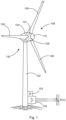
- the wind turbine 100 has a tower 102 and a nacelle 104 on the tower 102 .
- An aerodynamic rotor 106 with three rotor blades 108 and a spinner 110 is provided on the nacelle 104 .
- the aerodynamic rotor 106 is set in rotary motion by the wind and thus also rotates an electrodynamic rotor or rotor of a generator, which is directly or indirectly coupled to the aerodynamic rotor 106 .
- the electrical generator is arranged in the nacelle 104 and generates electrical energy.
- the pitch angles of the rotor blades 108 can be changed by pitch motors on the rotor blade roots 109 of the respective rotor blades 108 .
- the wind energy installation 100 has an electrical generator 101 which is indicated in the nacelle 104 . Electrical power can be generated by means of the generator 101 .
- a feed unit 105 is provided for feeding in electrical power, which feed unit can be designed in particular as an inverter.
- a three-phase feed current and/or a three-phase feed voltage can thus be generated according to amplitude, frequency and phase, for feeding at a grid connection point PCC. This can be done directly or together with other wind turbines in a wind farm.
- a system controller 103 is provided for controlling the wind energy system 100 and also the feed-in unit 105 . The system controller 103 can also receive default values from the outside, in particular from a central parking computer.
- FIG. 2 shows a wind farm 112 with, for example, three wind turbines 100, which can be the same or different.
- the three wind turbines 100 are therefore representative of basically any number of wind turbines in a wind farm 112 .
- the currents or powers generated by the individual wind turbines 100 are added up and a transformer 116 is usually provided, which steps up the voltage in the park in order to then feed it into the supply grid 120 at the feed point 118, which is also generally referred to as PCC.
- 2 11 is only a simplified representation of a wind farm 112.
- the farm network 114 can be designed differently, for example by also having a transformer at the output of each wind turbine 100, just to name another exemplary embodiment.
- the wind farm 112 also has a central farm computer 122, which can also be synonymously referred to as a central farm controller. This can be connected to the wind energy installations 100 via data lines 124 or wirelessly in order to exchange data with the wind energy installations and in particular to obtain measured values from the wind energy installations 100 and to transmit control values to the wind energy installations 100 .
- a central farm computer 122 which can also be synonymously referred to as a central farm controller. This can be connected to the wind energy installations 100 via data lines 124 or wirelessly in order to exchange data with the wind energy installations and in particular to obtain measured values from the wind energy installations 100 and to transmit control values to the wind energy installations 100 .
- FIG. 3 shows a diagram to illustrate possible frequency divisions with a frequency line 300 on which possible oscillation frequencies are plotted in Hz.
- a first frequency range 301 and a second frequency range 302 are shown as examples. These first and second frequency ranges 301 and 302 indicate ranges in which the detection and damping of a low-frequency oscillation is of interest. Such frequency ranges can vary depending on the electrical supply network or network section of an electrical supply network.
- 3 shows an example of a first, second and third partial frequency range 311, 312 and 313.
- the first two partial frequency ranges 311 and 312 cover the first frequency range 301 and all three partial frequency ranges 311 to 313 cover the second frequency range 302 .
- all three partial frequency ranges 311 to 313 can also be used to detect a low-frequency oscillation for the first range 301 . If a low-frequency oscillation is detected outside of the first region 301, it can be rejected or does not need to be considered any further.
- a time window with a length of 25 seconds and a resolution of 0.5 seconds is provided for the first partial frequency range 311 .
- a time window with a length of 12.5 seconds and a resolution of 0.25 seconds is provided for the second partial frequency range 312 .
- a time window with a length of 5 seconds and a resolution of 0.1 second is provided for the third partial frequency range 313 .
- FIG. 4 shows a damping control structure 400 for determining a desired damping signal for damping a low-frequency vibration.
- the damping control structure 400 has a signal input 402 at which the mains voltage or a mains signal exhibiting the low-frequency oscillations is input.
- the mains voltage can thus be recorded directly and entered there, i.e. a recorded mains signal.
- the mains voltage is recorded by detecting three phase-to-earth voltages of the three-phase system.
- a space vector is calculated from this and only the amplitude of this space vector is considered.
- the nominal voltage i.e. a fixed value, can be subtracted from the amplitude of this space vector. Only a difference between the amplitude of the space vector and the fixed mains voltage value then remains. This difference can be entered at the signal input 402 .
- This difference is therefore an input signal or mains signal that still has the low-frequency oscillations because only a constant value was subtracted.
- This input signal is then routed via the signal process block 404, which can carry out a first filtering in order to filter out measurement noise in particular.
- the signal process block 404 can thus have a low-pass behavior in particular.
- a pre-filtered or pre-processed signal S 1 is thus output at the output of the signal processing block 404 and input into one of the analysis blocks 411 to 413 .
- a network error can preferably be detected, for example a voltage dip. If a network fault is detected, a signal detected before the network fault or a signal or value representative thereof, such as an average value, can be used during the network fault instead of the detected or measured signal. This applies in particular to a very short network error in the range from 100 to 500 ms.
- the proposed damping of vibrations is usually important after a grid fault. The proposed bridging of the voltage dip during the measurement can ensure that the low-frequency oscillation is quickly and accurately recorded after the fault.
- each of the three analysis blocks carries out a frequency analysis for a partial frequency range.
- each of the three analysis blocks 411 to 413 has its own time window and its own resolution. This could be done, for example, for three different partial frequency ranges 311 to 313 with the corresponding window lengths and resolutions, as in 3 was explained.
- each of the three analysis blocks 411 to 413 can be an identified low-frequency oscillation. However, it is of course also possible that no low-frequency oscillation is present and therefore none can be detected. It is also conceivable that a plurality of low-frequency oscillations are detected in one or more of the analysis blocks.
- a low-frequency oscillation is detected in each of the three analysis blocks 411 to 413.
- the respective analysis block 411 to 413 outputs the frequency and amplitude and transfers these values to a coordination unit 406.
- These recognized low-frequency oscillations are evaluated in the coordination unit 406 .
- the target vibration One of the remaining low-frequency vibrations is identified as the target vibration and only this is then considered further. It is particularly important that the low-frequency vibration that has the greatest amplitude of all identified and relevant low-frequency vibrations is considered to be the target vibration. However, it is also possible to consider a different or further criterion. For example, a quotient of amplitude and oscillation frequency can be formed for each low-frequency oscillation, and the low-frequency oscillation with the largest quotient calculated here can be identified as the target oscillation, to name a further example.
- all three analysis blocks 411 to 413 which are also representative of a different number of analysis blocks, identify a total of only a single low-frequency oscillation, which then automatically forms the target oscillation.
- the oscillation frequency of the target oscillation identified in this way is output at frequency output 408 as oscillation frequency f PSOD of the low-frequency oscillation to be damped.
- This frequency f PSOD can be referred to as the damping frequency f PSOD for the sake of simplicity.
- This roll-off frequency f PSOD is then input to a bandpass filter block 410 .
- the bandpass filter block 410 is then adjusted according to the inputted attenuation frequency f PSOD , namely in particular such that the attenuation frequency f PSOD forms the bandpass filter frequency.
- the bandpass filter block 410 which is now set to the damping frequency f PSOD , can thus receive the pre-filtered signal S 1 as an input signal.
- the coordination unit 406 can output an initialization trigger Ti, which then namely has the value 1.
- the pre-filtered signal S 1 is multiplied by the initialization trigger Ti.
- the pre-filtered signal S 1 is thus passed through to the bandpass filter block 410 .
- the initialization trigger Ti can only assume the values 0 or 1. Before the initialization, the coordination unit 406 only outputs the value 0 as the initialization trigger Ti.
- the pre-filtered signal S 1 is then passed through the bandpass filter block 410 and of course it also has the low-frequency oscillation identified as dominant.
- the bandpass filter block 410 or the bandpass filter implemented therein is now precisely adapted to the dominant low-frequency oscillation to be damped, with the result that the pre-filtered signal S 1 , which initially still has all frequency components, now only the target vibration to be damped is passed through and everything else is filtered out.
- the bandpass filter block 410 therefore outputs the vibration signal Sd to be damped and transfers it to the determination controller block 416.
- the determination controller block 416 converts the vibration signal Sd to be damped into a desired damping signal Q PSOD .
- the determination controller block 416 can in particular change the amplitude and phase of the oscillation signal Sd to be damped and, if necessary, carry out further transformations such as filtering. Details on this are provided below figure 5 which basically shows the internal structure of the determination ruler block 416.
- the desired damping signal Q PSOD is to be superimposed on a further signal for damping, in order thereby to generate a desired feed signal which contains this desired damping signal. Details on this are described further below. First of all, however, it is provided that the amplitude of the desired damping signal Q PSOD generated by the determination controller block 416 can be increased slowly for activation, in particular from zero.
- An output multiplier 418 is provided for this purpose.
- the desired damping signal Q PSOD can be multiplied by a value in the output multiplier 418, which can rise from 0 to 1, for example as a ramp. Such a value can be output by the coordination unit 406 as an output trigger T A .
- This output trigger T A can also be output as output trigger T A in order to then be used as an activation indicator in subsequent control structures.
- the damping control structure 400 thus receives an input signal So, which is basically representative of the entire mains voltage signal, and depending on this, the damping control structure 400 outputs the damping setpoint signal Q PSOD in addition to the output trigger T A , which can act as an activation indicator.
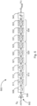
- FIG. 12 shows a structure with reshaping elements, many of which may also be referred to as filters, that may be included in the determination controller block 416.
- FIG. The vibration signal Sd to be damped can be input at the converter input 502 of the converter structure 500 . It is possible that only the normalized differential voltage is entered here, for example as a percentage value related to the nominal voltage. The voltage difference is therefore, as explained above, the amplitude of the space vector calculated from the three voltage values of the three phases minus the value of the nominal voltage. The nominal voltage can correspond to 100%.
- This input signal can first be passed through an amplifier 504 in order to amplify it.
- a low-pass filter element 506 can follow, which can further reduce any remaining noise component.
- FIG. 5 shows three examples, each with three members. However, more or, in particular, fewer links can also be provided in each case.
- the elements are linear, they may be arranged in an order other than that shown. However, the proposed sequence can be advantageous if the calculation is not arbitrarily precise and signal reproduction is not arbitrarily precise.
- the low-pass filter element 506 is followed by a high-pass filter element 510, which is made up of three high-pass filter elements 511 to 513 here.
- the high-pass filter element 510 is provided for filtering out remaining low-frequency signal components from the oscillation signal to be damped. Such low-frequency signal components can occur particularly due to wind energy installations feeding in due to wind fluctuations.
- the low-pass filter element 506 and the high-pass filter element 510 are tuned to the roll-off frequency f PSOD . Therefore, this damping frequency f PSOD is entered into the determination controller block 416 and can thus be used in this converter structure 500 of the figure 5 are taken into account.
- the low-pass filter element 506, the high-pass filter element 510 and the lead-lag elements or lead-lag elements explained below can also be set as a function of the damping frequency f PSOD .
- the low-pass filter element 506 is set in such a way that its cut-off frequency is above the roll-off frequency fPSOD .
- the high-pass filter element 510 or the high-pass filter elements 511 to 513 are set in such a way that their cut-off frequency or cut-off frequencies is or are below the damping frequency f PSOD .
- the high-pass filter element 510 is followed by a first lead-lag filter element 520, which is constructed from three individual lead-lag filter elements 521 to 523.
- a higher selectivity can be achieved by using a plurality of filter elements, in this case the three lead-lag filter elements 521 to 523. This also applies to the high-pass filter element 510 and also to the second lead-lag filter element, which will be described below.
- a lead-lag filter can be used to achieve signal shifts that are frequency-dependent.
- the vibration signal to be damped in particular be shifted accordingly after the further filtering described, which further elaborates this vibration signal to be damped. This allows communication-related delay times to be compensated.
- a lead-lag filter which can also be referred to as a lead-lag element, can be implemented in that at least one filter element or filter element is designed as a lead element and another filter element or filter element as a lag filter or lag member is formed.
- a second lead-lag filter element 530 can be provided, which is also made up of three lead-lag filter elements 531 to 533 . It is also contemplated that the first lead-lag filter element 520 operates essentially as a lead element in the frequency range under consideration, whereas the second lead-lag filter element 530 operates essentially as a lag element in the frequency range under consideration.
- a limiting element 540 is also provided, with which the generated signal can be limited if necessary. This can prevent an undesirably high signal amplitude from occurring as a result of the processing with the various filter elements. Such an undesirably high signal amplitude can also occur when the vibration signal to be damped has a correspondingly high amplitude. Generating a corresponding desired damping signal, which also has a high amplitude, would be appropriate in principle, but can have problems in implementation, so that this limitation is provided.
- a desired damping signal ⁇ Q PSOD is thus output by the converter structure 500, which can also be output as a percentage value.
- a maximum reactive power value of the feed-in device can be used as a reference here, which can correspond to the nominal power of the feed-in device.
- the designation with the Greek letter ⁇ indicates that this desired damping signal is to be superimposed on an existing signal. In particular after multiplication at the output multiplier 418 by the activation trigger T A , it can correspond to the desired damping signal Q PSOD .
- a corresponding reactive power signal is determined as the desired damping signal, and the elements or members in determination controller block 416 or converter structure 500 are adapted to this.
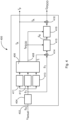
- Figures 6 to 8 show alternative structures for generating a feed target signal dependent on a base target signal and dependent on an attenuation target signal. All three structures of the Figures 6 to 8 build on a structure with a core controller 602, 702 or 802. Such a core controller is provided for converting a base target signal that does not yet have a target damping signal.
- This basic reactive power target signal Qs should be fed in as a feed signal, at least as long as no target attenuation signal is taken into account, and for this purpose the core controller generates a controller output signal Q A . Without taking into account the desired damping signal, this can correspond to a desired feed-in signal Q E .
- the core controller receives a control error e as an input signal (can also be referred to synonymously as a control deviation) as the result of a target/actual value comparison between the basic reactive power target signal Qs and a reactive power signal Qi actually fed in. Deviations between the basic reactive power setpoint signal Qs and the reactive power signal Qi actually fed in, i.e. the actual value, can result in particular from the behavior of the feed unit, i.e. in particular an inverter arrangement, and possibly other electrical components such as chokes, transformers and transmission lines.
- FIG 6 An overall structure 600 is presented, in which the target attenuation signal Q PSOD is applied to the base reactive power target signal Qs at a first summing element 604 .
- a modified base reactive power setpoint signal Qs′ results and, in addition to this, the control error e is formed at the second summing element 606 .
- the control error e is then input to the core controller 602 as before.
- the damping setpoint signal is generated by the damping controller 601, which essentially corresponds to the damping control structure 400 of FIG 4 can match.
- the attenuation controller 601 also receives an input signal So, which corresponds to the input signal So 4 can match.
- FIG. 6 thus shows a simple variant in which there is the problem that the previous core controller 602 also has to take this additional desired damping signal into account.
- a core controller 602 is often provided for the conversion of a substantially constant desired reactive power signal, that is to say a basic desired reactive power signal Q S , and is therefore not necessarily provided for correcting an oscillating desired signal.
- this core controller 602 is fast enough, that is to say it is designed fast enough and/or the vibration to be damped is slow enough or a correspondingly slow vibration to be damped is expected, the structure of the 6 be used.
- FIG. 7 shows an overall structure 700 in which the desired damping signal Q PSOD is applied to the controller output signal Q A downstream of the core controller 702 at a second summing element 706 . This directly results in the desired feed-in signal Q E .
- an attenuation controller 701 is provided, which essentially corresponds to the attenuation control structure 400 of FIG 4 can correspond and also can get the same input signal So.
- a first summing element 704 is also provided, which forms a control error e, namely from the difference between the base reactive power setpoint signal Qs and the fed-in reactive power actual value Qi.
- the control error e also includes an applied damping signal that is fed in superimposed on the desired damping signal.
- the desired damping signal Q PSOD By applying the desired damping signal Q PSOD to the second summing element 706, the reactive power fed in deviates from the basic desired reactive power signal Qs by this desired damping signal Q PSOD because of the modified desired feed signal Q E .
- the fed-in reactive power actual value Qi is changed accordingly as a result. This can lead to the core controller 702 attempting to correct this resulting, varying control error.
- the core controller 702 is sufficiently slow compared to the vibration signal Sd to be damped and thus compared to the desired damping signal Q PSOD , then this simple overall structure 700 can be suitable or at least sufficient.
- the overall structure 800 basically provides for the desired attenuation signal Q PSOD to be applied to the controller output signal Q A at a second summing element 806 in order to obtain the desired feed signal Q E in this way.
- the fed-in reactive power actual value Qi is made for the damping signal fed in according to the desired damping signal. In this way it can be achieved that the core controller 802 neither has to convert the desired damping signal nor is it influenced by it in the control error e.
- the actual reactive power signal Qi that is fed in is routed via a bandpass filter 810 .
- the bandpass filter 810 can correspond to the bandpass filter block 410 of the 4 and also receives the damping frequency f PSOD as an input value, namely from the damping controller 801, which can essentially correspond to the damping control structure 400.
- Bandpass filter 810 filters a compensation signal component from the recorded feed signal, ie from actual reactive power signal Qi.
- the compensation signal component corresponds, at least in terms of its frequency, to a damping signal Qd corresponding to the desired damping signal Q PSOD .
- damping signal Qd thus actually does not correspond exactly to the desired damping signal Q PSOD , so that the desired damping signal Q PSOD cannot simply be used for cleaning either.
- the compensation signal component generated in this way is subtracted as an attenuation compensation signal in a third summing element 808 from the reactive power actual signal Qi.
- a reactive power signal that has been corrected for the damping signal Qd remains, which is subtracted from the base reactive power target signal Qs in the first summing element 804 in order to form the control error e, which has accordingly been corrected for the damping signal Qd.
- the generation or output of the desired damping signal Q PSOD depends on the initialization trigger Ti and the activation trigger T A .
- This initialization or activation is thus also implemented in the overall structure 800 by an input multiplier 814 and an output multiplier 818 .
- the correction of the reactive power actual signal Qi at the third summing element 808 is not active even if no nominal damping signal Q PSOD is generated or output.
Landscapes
- Engineering & Computer Science (AREA)
- Power Engineering (AREA)
- Measurement Of Mechanical Vibrations Or Ultrasonic Waves (AREA)
- Control Of Eletrric Generators (AREA)
Priority Applications (4)
| Application Number | Priority Date | Filing Date | Title |
|---|---|---|---|
| EP21203591.9A EP4170848A1 (fr) | 2021-10-20 | 2021-10-20 | Procédé d'amortissement des vibrations basse fréquence dans un réseau d'alimentation électrique |
| CA3179034A CA3179034A1 (fr) | 2021-10-20 | 2022-10-12 | Methode d'attenuation des oscillations basse frequence dans un reseau d'alimentation electrique |
| US17/969,460 US11757284B2 (en) | 2021-10-20 | 2022-10-19 | Method for attenuating low-frequency oscillations in an electrical power supply grid |
| CN202211287020.2A CN115995826A (zh) | 2021-10-20 | 2022-10-20 | 用于衰减供电网中的低频振荡的方法和风能系统 |
Applications Claiming Priority (1)
| Application Number | Priority Date | Filing Date | Title |
|---|---|---|---|
| EP21203591.9A EP4170848A1 (fr) | 2021-10-20 | 2021-10-20 | Procédé d'amortissement des vibrations basse fréquence dans un réseau d'alimentation électrique |
Publications (1)
| Publication Number | Publication Date |
|---|---|
| EP4170848A1 true EP4170848A1 (fr) | 2023-04-26 |
Family
ID=78332569
Family Applications (1)
| Application Number | Title | Priority Date | Filing Date |
|---|---|---|---|
| EP21203591.9A Pending EP4170848A1 (fr) | 2021-10-20 | 2021-10-20 | Procédé d'amortissement des vibrations basse fréquence dans un réseau d'alimentation électrique |
Country Status (4)
| Country | Link |
|---|---|
| US (1) | US11757284B2 (fr) |
| EP (1) | EP4170848A1 (fr) |
| CN (1) | CN115995826A (fr) |
| CA (1) | CA3179034A1 (fr) |
Citations (10)
| Publication number | Priority date | Publication date | Assignee | Title |
|---|---|---|---|---|
| WO2005088802A1 (fr) * | 2004-03-08 | 2005-09-22 | A. Eberle Gmbh & Co. Kg | Dispositif de prevention de grandes pannes dans des reseaux d'alimentation electrique |
| US6965174B2 (en) | 2001-04-24 | 2005-11-15 | Aloys Wobben | Method for operating a wind turbine |
| US20130176751A1 (en) * | 2012-01-05 | 2013-07-11 | Ingeteam Power Technology, S.A. | Method and apparatus for controlling a frequency converter |
| WO2017129492A1 (fr) * | 2016-01-26 | 2017-08-03 | General Electric Technology Gmbh | Oscillations dans des réseaux électriques |
| EP3322060A1 (fr) * | 2016-11-14 | 2018-05-16 | Nordex Energy GmbH | Procédé d'amortissement d'oscillations électromécaniques dans un système électrique |
| EP3451482A1 (fr) * | 2017-08-28 | 2019-03-06 | General Electric Technology GmbH | Systèmes et procédés pour détecter et évaluer des oscillations dans un réseau électrique |
| EP3581791A1 (fr) * | 2018-06-13 | 2019-12-18 | Vestas Wind Systems A/S | Système de commande pour éoliennes permettant de réduire les perturbations dans un réseau électrique |
| WO2020007995A1 (fr) * | 2018-07-06 | 2020-01-09 | Wobben Properties Gmbh | Procédé pour commander un parc éolien de manière à atténuer des oscillations sous-synchrones |
| DE102018120768A1 (de) | 2018-08-24 | 2020-02-27 | Wobben Properties Gmbh | Windenergieanlage und Verfahren zum Erkennen niederfrequenter Schwingungen in einem elektrischen Versorgungsnetz |
| US20210208186A1 (en) | 2018-08-24 | 2021-07-08 | Wobben Properties Gmbh | Wind turbine and method for detecting low-frequency oscillations in an electrical supply grid |
-
2021
- 2021-10-20 EP EP21203591.9A patent/EP4170848A1/fr active Pending
-
2022
- 2022-10-12 CA CA3179034A patent/CA3179034A1/fr active Pending
- 2022-10-19 US US17/969,460 patent/US11757284B2/en active Active
- 2022-10-20 CN CN202211287020.2A patent/CN115995826A/zh active Pending
Patent Citations (10)
| Publication number | Priority date | Publication date | Assignee | Title |
|---|---|---|---|---|
| US6965174B2 (en) | 2001-04-24 | 2005-11-15 | Aloys Wobben | Method for operating a wind turbine |
| WO2005088802A1 (fr) * | 2004-03-08 | 2005-09-22 | A. Eberle Gmbh & Co. Kg | Dispositif de prevention de grandes pannes dans des reseaux d'alimentation electrique |
| US20130176751A1 (en) * | 2012-01-05 | 2013-07-11 | Ingeteam Power Technology, S.A. | Method and apparatus for controlling a frequency converter |
| WO2017129492A1 (fr) * | 2016-01-26 | 2017-08-03 | General Electric Technology Gmbh | Oscillations dans des réseaux électriques |
| EP3322060A1 (fr) * | 2016-11-14 | 2018-05-16 | Nordex Energy GmbH | Procédé d'amortissement d'oscillations électromécaniques dans un système électrique |
| EP3451482A1 (fr) * | 2017-08-28 | 2019-03-06 | General Electric Technology GmbH | Systèmes et procédés pour détecter et évaluer des oscillations dans un réseau électrique |
| EP3581791A1 (fr) * | 2018-06-13 | 2019-12-18 | Vestas Wind Systems A/S | Système de commande pour éoliennes permettant de réduire les perturbations dans un réseau électrique |
| WO2020007995A1 (fr) * | 2018-07-06 | 2020-01-09 | Wobben Properties Gmbh | Procédé pour commander un parc éolien de manière à atténuer des oscillations sous-synchrones |
| DE102018120768A1 (de) | 2018-08-24 | 2020-02-27 | Wobben Properties Gmbh | Windenergieanlage und Verfahren zum Erkennen niederfrequenter Schwingungen in einem elektrischen Versorgungsnetz |
| US20210208186A1 (en) | 2018-08-24 | 2021-07-08 | Wobben Properties Gmbh | Wind turbine and method for detecting low-frequency oscillations in an electrical supply grid |
Also Published As
| Publication number | Publication date |
|---|---|
| CA3179034A1 (fr) | 2023-04-20 |
| US11757284B2 (en) | 2023-09-12 |
| CN115995826A (zh) | 2023-04-21 |
| US20230122376A1 (en) | 2023-04-20 |
Similar Documents
| Publication | Publication Date | Title |
|---|---|---|
| EP3095165B1 (fr) | Procédé et dispositif de réglage et/ou commande pour faire fonctionner une éolienne et/ou un parc éolien et éolienne et parc éolien correspondants | |
| EP3818608B1 (fr) | Procédé pour commander un parc éolien de manière à atténuer des oscillations sous-synchrones | |
| EP2872777B1 (fr) | Procédé pour commander un générateur électrique | |
| EP2244348B1 (fr) | Parc éolien doté de plusieurs éoliennes et procédé de réglage de l'alimentation d'un parc éolien | |
| EP1224721B1 (fr) | Procede pour reguler la puissance reactive et dispositif pour produire de l'energie electrique dans un reseau electrique | |
| WO2020008036A1 (fr) | Système éolien et procédé pour détecter des oscillations de basse fréquence dans un réseau d'alimentation électrique | |
| WO2020007970A1 (fr) | Procédé de détection d'oscillations à basse fréquence et dispositif de détection correspondant | |
| EP3097622B1 (fr) | Régulation d'un parc éolien avec comportement amélioré de saut de la valeur de consigne | |
| EP3033816B1 (fr) | Procédé permettant d'injecter de l'énergie électrique dans un réseau d'alimentation | |
| EP3639339A1 (fr) | Procédé d'injection de la puissance électrique dans un réseau d'alimentation électrique au moyen d'un dispositif d'injection commandé par un convertisseur | |
| DE102011081446A1 (de) | Verfahren zum Betreiben einer Windenergieanlage | |
| EP0175863B1 (fr) | Procédé pour envoyer des données sur la ligne d'un réseau de distribution de courant alternatif et émetteur pour la réalisation du procédé | |
| EP2273646A2 (fr) | Procédé pour la compensation de puissance réactive et dispositif de production d'énergie électrique dans un réseau électrique | |
| EP2893629B1 (fr) | Procédé et dispositif permettant de faire fonctionner un appareil de production de courant pourvu d'un onduleur | |
| EP2351204B1 (fr) | DISPOSITIF DE COMMANDE D'UNE MACHINE À INDUCTION À & xA;DOUBLE ALIMENTATION | |
| EP4170848A1 (fr) | Procédé d'amortissement des vibrations basse fréquence dans un réseau d'alimentation électrique | |
| DE102014016664A1 (de) | Verfahren zum Betreiben einer Windenenergieanlage mit komplexer Umrichtersteuerung und Vorrichtung hierfür | |
| EP0268160A1 (fr) | Méthode et appareil à réduire au moins un facteur de fréquence d'une pulsation périodique | |
| EP3841649A1 (fr) | Éolienne et procédé pour détecter des oscillations de basse fréquence dans un réseau d'alimentation électrique | |
| DE102016203123A1 (de) | Vorrichtung und Verfahren zur Regelung eines Wechselrichters | |
| DE102019115943A1 (de) | Verfahren zum Steuern einer Windenergieanlage | |
| EP3638899A1 (fr) | Éolienne à générateur à entraînement direct et filtre de générateur | |
| DE102010000838A1 (de) | Verfahren und Vorrichtung zum Aufsynchronisieren eines Generators in einem Netz | |
| DE3830100A1 (de) | Verfahren zur optimierung der abstimmung eines senders und anordnung zum durchfuehren des verfahrens | |
| EP3813218A1 (fr) | Procédé d'injection de l'énergie électrique dans un réseau d'alimentation électrique |
Legal Events
| Date | Code | Title | Description |
|---|---|---|---|
| PUAI | Public reference made under article 153(3) epc to a published international application that has entered the european phase |
Free format text: ORIGINAL CODE: 0009012 |
|
| STAA | Information on the status of an ep patent application or granted ep patent |
Free format text: STATUS: THE APPLICATION HAS BEEN PUBLISHED |
|
| AK | Designated contracting states |
Kind code of ref document: A1 Designated state(s): AL AT BE BG CH CY CZ DE DK EE ES FI FR GB GR HR HU IE IS IT LI LT LU LV MC MK MT NL NO PL PT RO RS SE SI SK SM TR |
|
| RIN1 | Information on inventor provided before grant (corrected) |
Inventor name: BOROUJENI MALEKIAN, KAVEH Inventor name: BUSKER, KAI |
|
| STAA | Information on the status of an ep patent application or granted ep patent |
Free format text: STATUS: REQUEST FOR EXAMINATION WAS MADE |
|
| 17P | Request for examination filed |
Effective date: 20231026 |
|
| RBV | Designated contracting states (corrected) |
Designated state(s): AL AT BE BG CH CY CZ DE DK EE ES FI FR GB GR HR HU IE IS IT LI LT LU LV MC MK MT NL NO PL PT RO RS SE SI SK SM TR |