EP4170848A1 - Method for damping low-frequency vibrations in an electrical supply network - Google Patents
Method for damping low-frequency vibrations in an electrical supply network Download PDFInfo
- Publication number
- EP4170848A1 EP4170848A1 EP21203591.9A EP21203591A EP4170848A1 EP 4170848 A1 EP4170848 A1 EP 4170848A1 EP 21203591 A EP21203591 A EP 21203591A EP 4170848 A1 EP4170848 A1 EP 4170848A1
- Authority
- EP
- European Patent Office
- Prior art keywords
- signal
- frequency
- damping
- target
- oscillation
- Prior art date
- Legal status (The legal status is an assumption and is not a legal conclusion. Google has not performed a legal analysis and makes no representation as to the accuracy of the status listed.)
- Pending
Links
- 238000013016 damping Methods 0.000 title claims abstract description 204
- 238000000034 method Methods 0.000 title claims abstract description 39
- 230000010355 oscillation Effects 0.000 claims abstract description 170
- 230000036961 partial effect Effects 0.000 claims abstract description 101
- 238000004458 analytical method Methods 0.000 claims abstract description 64
- 230000001419 dependent effect Effects 0.000 claims abstract description 22
- 238000002347 injection Methods 0.000 claims abstract description 10
- 239000007924 injection Substances 0.000 claims abstract description 10
- 238000005070 sampling Methods 0.000 claims description 27
- 230000004913 activation Effects 0.000 claims description 19
- 238000009434 installation Methods 0.000 claims description 15
- 238000001914 filtration Methods 0.000 claims description 11
- 230000009849 deactivation Effects 0.000 claims description 10
- 238000006243 chemical reaction Methods 0.000 claims description 9
- 238000004891 communication Methods 0.000 claims description 9
- 238000001514 detection method Methods 0.000 claims description 8
- 238000011156 evaluation Methods 0.000 claims description 4
- 230000003213 activating effect Effects 0.000 claims description 2
- 230000008859 change Effects 0.000 description 9
- 238000005259 measurement Methods 0.000 description 8
- 239000000243 solution Substances 0.000 description 8
- 230000008569 process Effects 0.000 description 5
- 238000012545 processing Methods 0.000 description 5
- 230000005540 biological transmission Effects 0.000 description 4
- 238000012937 correction Methods 0.000 description 4
- 230000010363 phase shift Effects 0.000 description 4
- 238000007493 shaping process Methods 0.000 description 4
- 230000003595 spectral effect Effects 0.000 description 4
- 230000003321 amplification Effects 0.000 description 3
- 230000008901 benefit Effects 0.000 description 3
- 230000000694 effects Effects 0.000 description 3
- 238000003199 nucleic acid amplification method Methods 0.000 description 3
- 238000001228 spectrum Methods 0.000 description 3
- 230000009466 transformation Effects 0.000 description 3
- 230000006978 adaptation Effects 0.000 description 2
- 230000003044 adaptive effect Effects 0.000 description 2
- 230000033228 biological regulation Effects 0.000 description 2
- 238000010276 construction Methods 0.000 description 2
- 230000003247 decreasing effect Effects 0.000 description 2
- 238000010586 diagram Methods 0.000 description 2
- 230000005284 excitation Effects 0.000 description 2
- 230000002238 attenuated effect Effects 0.000 description 1
- 230000015572 biosynthetic process Effects 0.000 description 1
- 238000004140 cleaning Methods 0.000 description 1
- 239000012141 concentrate Substances 0.000 description 1
- 230000001276 controlling effect Effects 0.000 description 1
- 230000006866 deterioration Effects 0.000 description 1
- 230000005520 electrodynamics Effects 0.000 description 1
- 230000001747 exhibiting effect Effects 0.000 description 1
- 230000006872 improvement Effects 0.000 description 1
- 230000000670 limiting effect Effects 0.000 description 1
- 230000009467 reduction Effects 0.000 description 1
- 230000002829 reductive effect Effects 0.000 description 1
- 230000001105 regulatory effect Effects 0.000 description 1
- 230000000717 retained effect Effects 0.000 description 1
- 230000008054 signal transmission Effects 0.000 description 1
- 230000001629 suppression Effects 0.000 description 1
- 230000001360 synchronised effect Effects 0.000 description 1
- 238000012360 testing method Methods 0.000 description 1
- 238000000844 transformation Methods 0.000 description 1
- 238000011144 upstream manufacturing Methods 0.000 description 1
Images


Classifications
-
- H—ELECTRICITY
- H02—GENERATION; CONVERSION OR DISTRIBUTION OF ELECTRIC POWER
- H02J—CIRCUIT ARRANGEMENTS OR SYSTEMS FOR SUPPLYING OR DISTRIBUTING ELECTRIC POWER; SYSTEMS FOR STORING ELECTRIC ENERGY
- H02J3/00—Circuit arrangements for ac mains or ac distribution networks
- H02J3/24—Arrangements for preventing or reducing oscillations of power in networks
- H02J3/241—The oscillation concerning frequency
-
- H—ELECTRICITY
- H02—GENERATION; CONVERSION OR DISTRIBUTION OF ELECTRIC POWER
- H02J—CIRCUIT ARRANGEMENTS OR SYSTEMS FOR SUPPLYING OR DISTRIBUTING ELECTRIC POWER; SYSTEMS FOR STORING ELECTRIC ENERGY
- H02J3/00—Circuit arrangements for ac mains or ac distribution networks
- H02J3/38—Arrangements for parallely feeding a single network by two or more generators, converters or transformers
- H02J3/381—Dispersed generators
-
- F—MECHANICAL ENGINEERING; LIGHTING; HEATING; WEAPONS; BLASTING
- F03—MACHINES OR ENGINES FOR LIQUIDS; WIND, SPRING, OR WEIGHT MOTORS; PRODUCING MECHANICAL POWER OR A REACTIVE PROPULSIVE THRUST, NOT OTHERWISE PROVIDED FOR
- F03D—WIND MOTORS
- F03D7/00—Controlling wind motors
- F03D7/02—Controlling wind motors the wind motors having rotation axis substantially parallel to the air flow entering the rotor
- F03D7/028—Controlling wind motors the wind motors having rotation axis substantially parallel to the air flow entering the rotor controlling wind motor output power
- F03D7/0284—Controlling wind motors the wind motors having rotation axis substantially parallel to the air flow entering the rotor controlling wind motor output power in relation to the state of the electric grid
-
- H—ELECTRICITY
- H02—GENERATION; CONVERSION OR DISTRIBUTION OF ELECTRIC POWER
- H02J—CIRCUIT ARRANGEMENTS OR SYSTEMS FOR SUPPLYING OR DISTRIBUTING ELECTRIC POWER; SYSTEMS FOR STORING ELECTRIC ENERGY
- H02J2300/00—Systems for supplying or distributing electric power characterised by decentralized, dispersed, or local generation
- H02J2300/20—The dispersed energy generation being of renewable origin
- H02J2300/28—The renewable source being wind energy
-
- Y—GENERAL TAGGING OF NEW TECHNOLOGICAL DEVELOPMENTS; GENERAL TAGGING OF CROSS-SECTIONAL TECHNOLOGIES SPANNING OVER SEVERAL SECTIONS OF THE IPC; TECHNICAL SUBJECTS COVERED BY FORMER USPC CROSS-REFERENCE ART COLLECTIONS [XRACs] AND DIGESTS
- Y02—TECHNOLOGIES OR APPLICATIONS FOR MITIGATION OR ADAPTATION AGAINST CLIMATE CHANGE
- Y02E—REDUCTION OF GREENHOUSE GAS [GHG] EMISSIONS, RELATED TO ENERGY GENERATION, TRANSMISSION OR DISTRIBUTION
- Y02E10/00—Energy generation through renewable energy sources
- Y02E10/70—Wind energy
- Y02E10/76—Power conversion electric or electronic aspects
Definitions
- the present invention relates to a method for damping low-frequency oscillations in an electrical supply network by means of a feed device that feeds into the electrical supply network, in particular by means of a wind turbine.
- the present invention relates to a corresponding wind energy installation.
- Wind energy installations are known, they feed electrical power into an electrical supply network and are often also used to support the electrical supply network.
- it is known to feed in reactive power as a function of the mains voltage of the electrical supply network.
- a deviation of the mains voltage from a nominal mains voltage is considered and depending on this reactive power is fed in, which can be implemented by changing the phase angle of the current being fed in.
- Such a procedure is from the document U.S. 6,965,174 known.
- subsynchronous oscillations can occur in the electrical supply network. These can become noticeable as fluctuations in the voltage amplitudes. Such fluctuations can have frequencies below the nominal grid frequency, especially in the range of a few Hertz or even with frequencies below 1 Hz cause electrical oscillations in the network that cause other participants to react. These are essentially slow oscillations in the range of 0.1 Hz-1.5 Hz that are considered here. These are particularly inter-area vibrations, which are correspondingly slow, i.e. mostly below 1 Hz, rarely up to 1.5 Hz, or in one exception can reach 1.8 Hz.
- Such a detection has been proposed for checking for the presence of at least one subsynchronous oscillation over a frequency spectrum that can range over several orders of magnitude.
- it is possible to detect a subsynchronous oscillation with such a method but the method can have disadvantages for an implementation that also provides for damping of such subsynchronous oscillations.
- a higher quality of the detection is often required for the detection in order to provide an attenuation based thereon, but without such a large frequency spectrum having to be covered. It is particularly important that not every frequency in which a subsynchronous oscillation can occur must also be disruptive. Instead, damping of subsynchronous vibrations can often only be necessary in a narrowly specified frequency range.
- the damping of subsynchronous oscillations can be carried out by injecting reactive power.
- a damping reactive power feed can possibly collide with an above-mentioned voltage-dependent reactive power feed. It is therefore possible for a voltage-dependent reactive power feed to work against a reactive power feed that is intended to dampen subsynchronous oscillations.
- the present invention is therefore based on the object of addressing at least one of the problems mentioned above.
- a solution is to be proposed in which subsynchronous oscillations in a relevant frequency range are recognized and dampened, in particular with as little influence as possible on other grid-supporting feeds.
- an alternative solution to previously known solutions should be proposed.
- a feed device that feeds into the electrical supply network.
- a feed device can in particular be a wind energy plant.
- other decentralized feed-in devices can also be considered, e.g. feed from an energy store, from which a frequency converter is used to feed. Feeding in from other energy sources is also possible.
- the method is not suitable for directly coupled synchronous generators.
- the infeed devices that can be used here are therefore, in particular, converter-controlled infeed devices.
- so-called full converter concepts are proposed in which the entire power fed in is routed through a converter arrangement, so that the entire power fed in can be controlled by the converter arrangement in terms of amplitude, frequency and phase.
- An electrical supply network is assumed that has a network frequency, in particular the usual 50 Hz or 60 Hz. According to one step, it is proposed to record a network signal that has the low-frequency oscillations. In particular, a mains voltage is detected here. Of course, it can also happen that it turns out that there are no low-frequency vibrations at all. However, this network signal potentially exhibits the low-frequency oscillations, or at least one.
- Each sub-frequency range has a low, high, and middle range frequency. If, for example, vibrations to be damped are to be expected in a frequency range of 1-5Hz, a partial frequency range can range from 1Hz to 3Hz and thus have 1Hz, 2Hz and 3Hz as the lower, middle and upper frequency range. Another partial frequency range can range from 2Hz to 4Hz and thus have 2Hz, 3Hz and 4Hz as the lower, middle and upper frequency range. A third sub-frequency range can range from 3Hz to 5Hz and have 3Hz, 4Hz and 5Hz as the lower, middle and upper range frequencies accordingly.
- the center range frequency can be chosen as the arithmetic mean of the low and high range frequencies.
- a low-frequency vibration to be damped as a target vibration, depending on the frequency analyzes of all partial frequency ranges. It was particularly recognized here that a number of vibrations with different vibration frequencies can be identified, but it is not necessarily expedient and/or possible to dampen all of these vibration frequencies.
- a proposed embodiment is to select a possible target oscillation only from oscillations with oscillation frequencies that are also to be damped.
- a frequency range in which vibrations are to be damped if they occur, is smaller than the frequency range examined overall.
- the overall frequency range can already be defined in such a way that it goes beyond such a frequency range in which oscillations are to be damped.
- relevant frequencies can no longer be optimally identified at the edge of the overall frequency range, in particular at the edge of a partial frequency range.
- Vibration as a target vibration can already include identifying its frequency. However, this can still mean an inaccurate identification of the frequency of this target vibration. To this end, it is then proposed to record the target vibration according to frequency and amplitude as precisely as possible. Optionally, a phase, i.e. the phase position of the target oscillation, can also be recorded. This can be helpful for the damping to be carried out, but is not absolutely necessary, as will be seen below.
- a target damping signal as a function of the target vibration detected according to frequency and amplitude and possibly also phase, in order to dampen the detected target vibration.
- a desired damping signal itself has the frequency of the target oscillation.
- Setting a phase of the desired damping signal is also advantageous in order to then generate a corresponding damping signal according to the desired damping signal, which also damps the target oscillation and does not excite it if the phase position is incorrect.
- a phase position of the desired damping signal and thus also of the damping signal does not necessarily have to be set as a direct function of a phase of the detected target oscillation.
- the detected target oscillation or a signal derived from it can otherwise influence the phase position of the damping setpoint signal and thus the damping signal.
- one option is to record the phase of the target vibration and to determine the phase of the damping setpoint signal based on this.
- such a desired damping signal does not necessarily have to be a sinusoidal signal, but one variant is that the desired damping signal is sinusoidal.
- the desired feed-in signal is therefore a specification for a feed-in signal, which can in particular be reactive power to be fed in, but can also be or contain active power.
- the injection signal is supposed to implement the damping, but there can be other tasks for the injection signal, e.g. to support a voltage. These additional tasks, or just one additional task, are specified by the base target signal.
- the intended damping and the other tasks are therefore taken into account together in the desired feed signal and then in the feed signal.
- the desired feed signal is then composed in particular of the desired damping signal and the basic desired signal.
- the feed signal is then made up of a base signal and the damping signal. are for each target signals provided, so the feed target signal for the feed signal, the base target signal for the base signal and the attenuation target signal for the attenuation signal.
- the feed signal is generated and fed in as a function of the desired feed signal. This can be done with the help of a converter arrangement.
- the damping signal can be a reactive power or a reactive current.
- the feeding in of a reactive power or a reactive current can already be provided as a base signal.
- a voltage-dependent reactive power feed is already implemented.
- Such a voltage-dependent reactive power feed essentially supplies a constant reactive power or a constant reactive current when the mains voltage is essentially constant.
- such a voltage-dependent reactive power feed basically reacts to low-frequency oscillations that are superimposed on the base voltage signal, with a reaction that can even lead to a deterioration, in particular excitation of the oscillation.
- the desired damping signal is recorded and switched to the basic desired signal.
- the amplitude of the target oscillation may be small compared to the amplitude of the mains voltage, so the mains voltage may have a small amount of variation, but the derived damping target signal may have a significant amplitude, which may be of the order of the base target signal or greater. Of course, it can also be lower, which also depends on how large such a voltage-dependent reactive power is in each case, to stay with this example.
- this superimposition creates a desired feed signal or feed signal, or it is proposed to generate and feed the feed signal as a function of the desired feed signal.
- a feed signal can then be generated and controlled, which contains the damping signal and also an already existing base signal.
- a damping reactive power signal or reactive current signal on a voltage-dependent Reactive power feed or reactive current feed can be coordinated. This joint consideration prevents the damping signal and the voltage-dependent generated base signal from working against each other.
- the desired damping signal describes a reactive power to be fed in and, in particular, that the basic desired signal is specified by reactive power control as a desired signal for a reactive power to be fed in.
- the reactive power control can, for example, implement a permanently specified reactive power target value, but grid-voltage-dependent reactive power feed-in can also be considered.
- the feed-in signal is then also made up of the reactive power according to the desired damping signal and the reactive power according to the basic desired signal.
- the damping of the low-frequency oscillation takes place by means of a corresponding reactive power signal.
- a voltage oscillation in particular can be counteracted.
- the active power that is fed in is varied, and as a result, mechanical stresses on the wind energy plant due to the varying provision of active power are avoided.
- an oscillating change in active power can lead to correspondingly oscillating mechanical loads on the generator, which can also be transferred to other parts of the wind energy installation. For example, the tower can vibrate, which is avoided in this way.
- a core controller is provided to generate the desired feed signal, which outputs a controller output signal as a function of the basic desired signal and the fed-in signal, and that the desired feed signal is determined as a function of the controller output signal.
- the desired damping signal or part of it be superimposed on the basic desired signal and thus be taken into account by the core controller.
- the desired damping signal or a part thereof is applied to the controller output signal and thereby influences the desired feed signal.
- a core controller is therefore provided, which can also be referred to synonymously as an inner controller or inner control loop.
- This core controller emits a controller output signal as a function of the basic setpoint signal and the feed signal that is fed in.
- a setpoint/actual value comparison is formed between the basic setpoint signal and the feed-in signal that is fed in, and this setpoint/actual value comparison, i.e. the resulting control error, thus forms the input signal of the core controller.
- the controller output signal then forms the basis for the feed setpoint signal.
- the feed setpoint signal corresponds to the controller output signal.
- the desired feed signal is thus the sum of the controller output signal and the desired damping signal or the part thereof that is superimposed.
- the desired feed signal results here exclusively from the controller output signal and the added damping desired signal. Since the desired damping signal can be a sinusoidal signal in particular, it can of course also be subtracted depending on the phase position.
- the base setpoint signal, the setpoint attenuation signal and, correspondingly, also the resulting setpoint feed signal is a setpoint signal for a reactive power in each case.
- the base target signal can be a reactive power target signal that a voltage-dependent reactive power controller has output or specified.
- This basic setpoint signal which would be specified by such a voltage-dependent reactive power controller, especially when vibration damping is deactivated, should be implemented as well as possible with the help of the core controller.
- the setpoint/actual value comparison is made between the basic setpoint signal and the feed-in signal, i.e. the reactive power actually fed in, and leads to a control error.
- the core controller issues the controller output signal.
- the controller output signal is then itself a reactive power reference value.
- a core controller which can be the innermost controller of a corresponding controller cascade, regulates in particular deviations that occur due to the converting converter or are caused by the influence of lines and/or transformers.
- transmission lines from a wind turbine to a grid connection point, especially if the wind turbine is part of a wind farm, can be relevant here.
- this core controller modifies the basic setpoint signal in such a way that it compensates for changes caused by conversion by converters and the influence of cables and transformers.
- this core controller modifies the basic setpoint signal in such a way that it compensates for changes caused by conversion by converters and the influence of cables and transformers.
- the desired damping signal is superimposed on the basic desired signal.
- the result is compared with the actual value of the feed signal and the resulting control error is converted by the core controller into a modified target signal, i.e. into the controller output signal.
- the desired damping signal can basically be switched on in a simple manner.
- the desired damping signal can be in the form of a sinusoidal signal in particular, and this means that the core controller, which is essentially designed for a stationary signal without this desired damping signal, has to constantly readjust an oscillating signal. This can lead to a phase shift of this oscillating part due to the core controller, because it was not originally designed for regulating such a sinusoidal signal.
- the core controller can in particular have an integral part, since it is intended to achieve stationary accuracy for use without a superimposed sinusoidal damping signal.
- an integral part can be unfavorable for the correction of an oscillating signal, or at least not work optimally.
- the core controller can then continue to regulate a stationary accuracy for the base setpoint signal, ie basically as in the case when no damping setpoint signal is applied.
- the oscillating desired damping signal is then applied to the resulting controller output signal, which means that it does not have to pass through the core controller.
- Deviations caused by converters and the influence of lines and transformers cannot then be corrected for the damping signal, but this can be acceptable.
- Frequency and phase position are particularly important for the damping signal. Any deviations in amplitude are of less importance. A phase shift can be taken into account in other ways, particularly when generating the desired damping signal.
- a damping compensation signal dependent on the desired damping signal is applied, in particular to the basic desired signal, in order to at least partially compensate for an influence of the desired damping signal via the fed-back signal on the core controller.
- the basic idea here is to remove the damping signal from the recorded and fed-back feed signal.
- a target actual value comparison can then be carried out between the basic target value and the detected, fed-back feed signal, which results in a control error or control deviation corrected for the damping signal, so that a control error correspondingly corrected for the damping signal is input into the core controller. Due to the linear linkage when forming the control error, it is not important where exactly the compensation signal component is applied for correction, in particular whether the application is made with the appropriate sign for correction on the base setpoint, the fed-back signal, or on the control error.
- the oscillating signal superimposed on the feed signal that is actually fed in is not necessarily identical to the desired attenuation signal applied beforehand. Accordingly, a signal can be generated that corresponds approximately to the resulting oscillating partial signal superimposed on the feed signal. This is superimposed on the returned injection signal with the sign reversed, so essentially the same to compensate for the superimposed partial signal. In the ideal case, a setpoint/actual value comparison then takes place between the basic setpoint signal and the feed-in signal which has been corrected for this superimposed oscillating partial signal.
- the damping compensation signal is switched on the input side of the core controller, which emits a controller output signal as a function of the base setpoint signal and the fed-in feed signal, in particular to the base setpoint signal.
- the attenuation compensation signal is generated by filtering out a compensation signal component from the recorded feed signal.
- the compensation signal component has an oscillation frequency of the identified target oscillation and the damping compensation signal is formed as a function of the compensation signal component.
- the attenuation compensation signal can correspond to the compensation signal component.
- the filter is thus adjusted in such a way that it filters out a signal component with the oscillation frequency of the identified target oscillation. In this way it can be achieved that essentially the damping signal is filtered out as a compensation signal component, but with a changed amplitude and phase position in comparison to the desired damping signal.
- the compensation signal component filtered out in this way can be used directly as an attenuation compensation signal.
- an adjustment of the amplitude and/or the phase can also be considered if the compensation signal component is converted into the attenuation compensation signal. It is also possible to make the connection of the damping compensation signal or the further processing of the compensation signal component dependent on criteria such as an amplitude of the desired damping signal.
- a bandpass filter can be used to filter out the damping compensation signal from the detected injection signal and tuned to the oscillation frequency of the identified target oscillation.
- the bandpass filter essentially only lets through signals with the oscillation frequency of the identified target oscillation.
- the underlying idea is to remove the damping signal from the recorded and fed-back feed signal.
- At least three overlapping partial frequency ranges be provided.
- at least four, at least five or at least six partial frequency ranges are provided.
- the frequency analysis of the network signal for each sub-frequency range is better the narrower the frequency range is selected.
- the lower range frequency of each sub-frequency range defines the minimum length of time over which the signal must be recorded and evaluated here. The lower range frequency therefore limits the speed of the evaluation.
- the upper range frequency defines a minimum sampling frequency, which can also be referred to synonymously as the sampling rate, and high frequencies should also be recorded as quickly as possible.
- the lower and upper frequency range of each partial frequency range are thus in a certain contradiction and it is therefore proposed to select the partial frequency ranges as small as possible.
- the selection of smaller partial frequency ranges and thus the use of a larger number of partial frequency ranges does not necessarily have to lead to a correspondingly higher computing capacity being required.
- the computing effort can be kept correspondingly small by a good adaptation of the measurement duration and sampling frequency.
- the upper range frequency of a partial frequency range is in the range of 1.5 times to 10 times the lower range frequency of the same partial frequency range.
- the upper range frequency of a sub-frequency range is in the range of two to three times the lower range frequency of the same sub-frequency range.
- a frequency spectrum from 1 Hz to 16 Hz can already be covered with twice the value of the upper range frequency compared to the lower range frequency and with a choice of four partial frequency ranges. With a small overlap, for example, a range of 0.5 - 5Hz can be covered. It was also recognized that, in order to take into account relevant low-frequency oscillations in the electrical supply network, covering such a frequency range of, for example, 0.5-5 Hz can be sufficient.
- the respective frequency analysis uses different time sections of the detected network signal for each partial frequency range and has different sampling rates. This allows the frequency analysis to be well adjusted for each partial frequency range.
- such a time section that is as small as possible is defined by the lower range frequency of the respective partial frequency range, so that the selection of the shortest possible time segments means that they are different for each partial frequency range.
- a sampling rate that is as high as possible would be desirable.
- the sampling rate should not be selected too high.
- the number of samples per time segment is therefore preferably chosen to be the same or similar for the partial frequency ranges.
- the advantage explained does not only result if this number of samples per time section is always exactly the same.
- each partial frequency range is assigned a time segment of the network signal for evaluation, with time segments of several partial frequency ranges overlapping, and the time segment is larger the smaller the lower range frequency of the assigned partial frequency range is, and/or each partial frequency range for carrying out the frequency analysis is assigned a sampling rate that is greater the greater the upper range frequency of the partial frequency range.
- a number of samples per time section be used that is the same for different partial frequency ranges, in particular for all partial frequency ranges.
- a time segment of the network signal is therefore a section of the network signal that is analyzed in each case. It is of different length for different partial frequency ranges.
- the partial frequency ranges are evaluated as far as possible, ie also preferably, in an online calculation.
- the analysis for all partial frequency ranges also takes place in parallel or at the same time.
- the respective time excerpts are of different lengths, but appear at the same time, insofar as they are at least overlapping.
- the time sections can be implemented as sliding windows. Then the current time sections of each partial frequency range could have the same end time, which in turn is constantly renewed.
- the choice of the length of the time segment is therefore decisive.
- the length of the time segment is therefore based on the lower range frequency.
- the evaluation or calculation can be updated for the different partial frequency ranges at the same time.
- the time windows of different lengths go back different distances from such an update time, so that the end times, ie usually about the current time, are the same, but the start times are different.
- the sampling rate can be based on the size of the time section and can result in particular from the fact that a fixed number of samples per time section is specified. In addition or as an alternative, the sampling rate can also be based on the upper range frequency. After all, the sampling rate must be chosen so large that even the highest oscillation frequency still to be analyzed in the respective partial frequency range is sampled with a sufficiently high sampling rate.
- the duration of the time segment of the partial frequency range corresponds to at least half, in particular at least the entire reciprocal value of the lower range frequency.
- the duration of the time section of the partial frequency range corresponds to at least half a period. It was recognized that half the period of a signal can be sufficient to identify it.
- the duration of the time segment corresponds at most to five times the reciprocal value of the lower range frequency. It is therefore proposed to carry out the analysis over a maximum period of five times the longest period. In principle, an analysis can also take longer, but it should be noted that the result of the analysis should be available as early as possible. Choosing a time section that is too long results in an analysis time that is too long, which is avoided by setting the upper value of the time section.
- the sampling rate of a partial frequency range corresponds to at least twice, in particular at least five times, the upper range frequency. This ensures that sufficiently high sampling is performed even for signals in the upper frequency range.
- a technical lower limit is double the sampling rate of a frequency.
- the sampling rate of a partial frequency range corresponds at most to 100 times, in particular at most to 50 times, the upper range frequency.
- the sampling rate could be chosen as high as desired, but for practical reasons it was recognized that too high a sampling rate requires too much computing power.
- the sampling rate is based on the upper range frequency, the lower range frequency determines or influences the measurement duration.
- a solution is therefore proposed here in which measurements are taken for a sufficiently long time for the lower range frequency, sampling is carried out sufficiently frequently for the upper range frequency and all of this can also be evaluated in the shortest possible time.
- an oscillation with an oscillating frequency was detected in a first of the partial frequency ranges with a higher upper range frequency than at least one other partial frequency range, this oscillating frequency is taken into account as a potential aliasing frequency.
- a filtered signal of the network signal is then used for the frequency analysis of at least a second of the partial frequency ranges with a lower upper range frequency than in the case of the first partial frequency range. Signal components with the aliasing frequency are filtered out of this filtered signal.
- the partial frequency ranges can detect oscillations of different oscillation frequencies.
- a high frequency oscillation is detected in a high upper frequency sub-frequency range, it will still occur in lower upper frequency frequency sub-frequency ranges because it naturally occurs throughout the recorded mains signal.
- they may not be able to be identified in such sub-frequency ranges with a lower upper range frequency, because the frequency analysis adapted to the respective sub-frequency range, especially the sampling rate, is not designed for such frequencies.
- the frequency analysis is carried out for each partial frequency range in order to identify at least one oscillation with a first frequency.
- the frequency, amplitude and optionally the phase of the vibration identified in the first analysis step be identified by means of a signal examination adapted to the identified vibration.
- the adjusted signal analysis of the identified vibration has a higher resolution than the frequency analysis that identified the vibration in the first analysis step and/or is specifically tuned to the first frequency identified in the first analysis step.
- the analysis may only result in a vibration with a frequency of 1.2 Hz being detected. The exact frequency could not be identified.
- a higher resolution and/or targeted tuning to this first frequency of 1.2 Hz is carried out in such a more precisely delimited frequency range, that is to say in the example in the range from 1.1 Hz to 1.3 Hz.
- spectral lines to be examined can be selected and such a selection is made for the second pass depending on the result of the first examination.
- a window with a duration (window length) of 50s can be used, for which 50 points are provided.
- the length specifies the frequency resolution, in this case 1/50 Hz. Therefore, the spectral lines can be calculated with a resolution of 1/50 Hz, up to a maximum frequency that depends on the time resolution.
- the examination can therefore cover a range from DC-1Hz, with a resolution of 50 values. If, for example, 0.8Hz occurs during the first iteration, it is initially no longer possible to be more precise because the increment is fixed because no new measurements are taken. The analysis can then be improved by a further measurement, in particular parallel measurement with higher resolution.
- phase angle of the reference signal is changed by m iterations in a loop in the complete range, ie for 0 to 2 ⁇ or 0° to 360°.
- frequency of the reference signal is changed in a further loop by n iterations in the frequency range to be examined.
- the frequency range to be examined is very limited due to the vibration found in the first analysis step.
- the frequency range is limited from initially 1Hz to 2Hz to now 1.1Hz to 1.3Hz.
- the frequency and phase angle at which the DC component of the product is highest can be taken as the frequency and phase angle of the low-frequency oscillation.
- the magnitude of the low-frequency oscillation can also be determined.
- a calculation can be carried out in particular as described in the German Offenlegungsschrift DE 102018120768 A1 is described, namely to the Figures 3 and 4 , in paragraphs [0059] to [0098].
- an input signal which corresponds to the recorded mains signal or is derived from it, is filtered with a bandpass filter in order to determine the desired attenuation signal.
- the bandpass filter be set as a function of the identified target oscillation, to pass from the input signal a signal component with the oscillation frequency of the identified target oscillation to only pass the target oscillation from the input signal as extracted mains oscillation.
- the space vector can be calculated from the three phase-to-earth voltages and the amplitude can be taken from this.
- the nominal voltage ie a fixed value
- the nominal voltage is then subtracted from the amplitude of the space vector. This is based on the finding that the actual mains voltage signal, i.e. the 50Hz or 60Hz signal, dominates in terms of amplitude compared to the identified target oscillation.
- a very large signal component which cannot contain the target oscillation due to the artificial specification, can already be removed from the network signal.
- the input signal generated in this way essentially only has components that belong to superimposed oscillations.
- a mains oscillation is extracted which only has an oscillation with one frequency of the identified target oscillation.
- a second mains oscillation could also be extracted in the same way.
- the method preferably focuses on extracting a single mains oscillation.
- the conversion of the mains oscillation into the target damping signal is an amplification and a shift of 180°.
- it preferably relates in particular to the transformation into the physical unit of the target attenuation signal, ie in particular into a target attenuation signal which specifies a reactive power to be fed.
- an amplitude of the desired damping signal can also be set.
- the reshaping can also include a phase shift be provided so that the desired damping signal or the damping signal to be generated actually also dampens the identified target vibration and does not amplify it.
- the mains oscillation can be normalized in terms of its amplitude to the nominal voltage and the damping signal to the nominal reactive power.
- the gain can also be less than one.
- a mains oscillation is not identified, e.g. according to frequency, phase and amplitude, and a damping target signal is then generated depending on this, in which frequency, phase and amplitude are also specified again , but rather that the extracted mains oscillation, i.e. an extracted mains oscillation signal, is converted directly into the desired damping signal.
- the desired damping signal then also changes immediately if the extracted mains oscillation signal changes.
- the extracted mains oscillation signal is thus generated almost always up-to-date based on the currently input mains signal.
- target vibrations which can therefore be referred to as subsynchronous vibrations in particular, are based on resonance properties that can be caused by physical characteristics, particularly mechanical natural frequencies. These can affect other participants connected to the electrical supply network, especially power plants. This can lead to further excitation or amplification of vibrations.
- Such a fundamentally physically predetermined resonance is usually practically unchangeable in terms of its frequency. Only a hardware change, e.g. changed circuits in the electrical supply network, in particular switching large consumers or generators on or off, can cause a change. However, amplitudes can change more easily, as can phase shifts.
- At least one of the following conversion elements be used to convert the extracted mains oscillation into the desired damping signal.
- a low-pass filter can be used as a shaping element to filter out a noise component from the extracted mains oscillation.
- the extracted mains oscillation is itself, of course, also a signal that can be synonymously referred to here as a mains oscillation signal.
- this mains oscillation signal only shows the target oscillation, but in fact noise components can occur, e.g. due to the signal transmission paths and because the filters used do not work ideally.
- the extracted mains oscillation signal should be converted into the damping target signal. Even small noise components would then lead to corresponding components in the desired damping signal, which is to be avoided.
- Another possible shaping element is an amplifying element for amplifying the extracted mains oscillation.
- Such an amplification serves not only to ensure that the desired damping signal has a sufficient amplitude, but also to ensure that the amplitude of the desired damping signal or an intermediate signal can be significantly higher than an amplitude of possible interference.
- a high-pass filter is proposed as a further possible shaping element for filtering out low-frequency signal components.
- wind energy installations feed into the electrical supply network. These can introduce low-frequency voltage fluctuations due to wind fluctuations.
- Such a high-pass filter for filtering out such low-frequency signal components is also particularly suitable when the proposed method is implemented by wind turbines, in particular by a wind farm. Then such low-frequency signal components caused by wind fluctuations can occur in the network signal without them occurring in the electrical supply network, at least not to a significant extent.
- At least one lead-lag filter which can also be referred to as a lead-lag element, is proposed as a further shaping element.
- a lead-lag circuit includes a lead circuit and a lag circuit connected in series with each other.
- the term is also a technical term in the German professional world and could at best be referred to as a lead-delay filter or lead-delay element.
- Such a lead-lag filter is provided to compensate for communication-related delay times. Such communication-related delay times are generally well known and the lead-lag filter can be adjusted to compensate for such delay times compensated.
- two lead lag filters can be used, one with a higher frequency lead and one with a higher frequency lag. In a lead lag (or lead lag filter) with higher frequency lead, the lead lag has lead in a higher frequency range and lag in a lower frequency range on.
- the determination and/or application of the desired damping signal be activated or deactivated depending on a property of the identified target vibration, in particular depending on an amplitude of the identified target vibration.
- the target oscillation is provided in each case as a comparison value for the amplitude, and the activation threshold is greater than the deactivation threshold.
- the identification of the target oscillation remains unaffected, only the determination and/or application of the desired damping signal is activated or deactivated.
- the determination of the desired damping signal can always continue unchanged, since it can essentially be a computer-assisted process.
- the application of the desired damping signal can be carried out or suppressed or ended as desired.
- the application of such an attenuation target signal in particular the application of a corresponding reactive power signal, can also have at least a disruptive effect on the remaining operation of the feed device.
- a damping signal as reactive power
- a voltage-dependent reactive power feed is influenced. This should be avoided when the vibration is small.
- the amplitude of the identified target vibration is sufficiently high, it makes sense to apply the damping setpoint signal.
- a switch-on threshold should be higher than a switch-off threshold, ie the activation threshold should be greater than the deactivation threshold, in order to prevent a constant change between activation and deactivation taking place when the target oscillation is approximately in the threshold range.
- an activation function is generated, which increases the desired damping signal to be applied in a controlled manner at the beginning of the application, in particular according to a ramp function.
- a deactivation function is used to end the application of the damping signal, which deactivation function is used, which lowers the applied desired damping signal to end the application in a controlled manner, in particular according to a ramp function.
- the desired damping signal and thus the damping signal result from the extracted mains oscillation signal and can essentially be assumed to be a sinusoidal signal. Basically, it is not specified by parameters, but by conversion from the extracted vibration signal. If the damping signal is now switched on without an activation function, this can possibly happen exactly when the sinusoidal damping signal has a maximum positive or negative amplitude, which would then be switched on, which itself could possibly trigger an oscillation. The same applies to switching off. Therefore, the quasi-smooth intrusion or termination of the intrusion is proposed.
- the target vibration when several vibrations are detected, one is selected as the target vibration, in particular as a function of an amplitude, and in particular in such a way that the one with the greatest amplitude is selected as the target vibration from a number of detected vibrations.
- the desired damping signal be generated as a function of the selected target vibration and after the activation of the determination and/or application of the damping signal, the target vibration is maintained, and only after the determination or application has been deactivated, another of the detected vibrations is used as the target vibration is selected.
- vibrations can occur as a result, i.e. simply due to the switching process.
- a decrease in the initially identified target vibration would erroneously lead to the conclusion that it has generally decreased, although it has only decreased as a result of the damping. Switching off this damping, ie by changing to a different damping of a different oscillation, would immediately revive this initially selected target oscillation, which is to be avoided.
- the total frequency range can be specified, and that the total frequency range is automatically divided into the partial frequency ranges when the total frequency range is specified.
- a network operator specifies the overall frequency range, i.e. the range in which he considers low-frequency vibrations to be disruptive and prescribes vibration suppression there.
- the specification of such an overall frequency range can also mean that this is done only rarely or once for a feed device connected to the electrical supply network, especially as long as no new specification is made by a network operator.
- a feed device of the same construction ie a wind energy plant of the same construction, can, however, be given a different specification for the overall frequency range when connected to a different network connection point, in particular when connected to a different electrical supply network.
- the proposed division of the overall frequency range into the partial frequency ranges can easily be automated, e.g.
- the upper range frequency can, for example, always be twice as large as the lower range frequency.
- An overlap can also be specified from one partial frequency range to the next, e.g. in a percentage range.
- the lower range frequency of a sub-frequency range can be, for example, 10% below the upper range frequency of the next lower sub-frequency range.
- the feed-in signal is fed in by means of a wind farm comprising several wind turbines, the wind turbines each generating part of the feed-in signal, and each wind turbine taking into account the same target oscillation for generating the feed-in signal. It was particularly recognized here that such a wind farm can dampen vibrations particularly well if all wind energy installations dampen the same vibration.
- the proposed solution avoids this problem, or at least mitigates it. It is controlled centrally that all wind turbines use the same target vibration. This target vibration, especially its frequency, can then be used specifically for the bandpass filter. This can be done individually in each wind turbine and the further signal processing can also be done individually in each wind turbine, so that no large communication resources are required within the wind farm.
- an extracted mains oscillation or a corresponding extracted mains oscillation signal can be provided centrally in the park for all wind turbines.
- a converted target damping signal can of course also be considered as a central signal that a farm controller distributes to all wind turbines, provided that communication in the farm allows it.
- a wind energy system which comprises one or more wind energy installations.
- the wind energy system can therefore be a wind energy installation, or the wind energy system can be a wind farm with a number of wind energy installations.
- the wind energy system has at least one sensor for recording a grid signal that has the low-frequency oscillations, and the wind energy system has at least one control device that prepares for this is to carry out a method for damping low-frequency vibrations.
- the control device can also have an inverter or an inverter arrangement or converter arrangement for feeding electrical power and thus also for feeding reactive power into the electrical supply network.
- the wind energy system is prepared to carry out a method according to one of the embodiments or aspects described above.
- the control device is prepared to carry out the method.
- the measuring sensor can also be part of the control device. If the sensor is not part of the control device, the control device is prepared in particular to carry out the method steps that the sensor does not carry out.
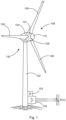
- the wind turbine 100 has a tower 102 and a nacelle 104 on the tower 102 .
- An aerodynamic rotor 106 with three rotor blades 108 and a spinner 110 is provided on the nacelle 104 .
- the aerodynamic rotor 106 is set in rotary motion by the wind and thus also rotates an electrodynamic rotor or rotor of a generator, which is directly or indirectly coupled to the aerodynamic rotor 106 .
- the electrical generator is arranged in the nacelle 104 and generates electrical energy.
- the pitch angles of the rotor blades 108 can be changed by pitch motors on the rotor blade roots 109 of the respective rotor blades 108 .
- the wind energy installation 100 has an electrical generator 101 which is indicated in the nacelle 104 . Electrical power can be generated by means of the generator 101 .
- a feed unit 105 is provided for feeding in electrical power, which feed unit can be designed in particular as an inverter.
- a three-phase feed current and/or a three-phase feed voltage can thus be generated according to amplitude, frequency and phase, for feeding at a grid connection point PCC. This can be done directly or together with other wind turbines in a wind farm.
- a system controller 103 is provided for controlling the wind energy system 100 and also the feed-in unit 105 . The system controller 103 can also receive default values from the outside, in particular from a central parking computer.
- FIG. 2 shows a wind farm 112 with, for example, three wind turbines 100, which can be the same or different.
- the three wind turbines 100 are therefore representative of basically any number of wind turbines in a wind farm 112 .
- the currents or powers generated by the individual wind turbines 100 are added up and a transformer 116 is usually provided, which steps up the voltage in the park in order to then feed it into the supply grid 120 at the feed point 118, which is also generally referred to as PCC.
- 2 11 is only a simplified representation of a wind farm 112.
- the farm network 114 can be designed differently, for example by also having a transformer at the output of each wind turbine 100, just to name another exemplary embodiment.
- the wind farm 112 also has a central farm computer 122, which can also be synonymously referred to as a central farm controller. This can be connected to the wind energy installations 100 via data lines 124 or wirelessly in order to exchange data with the wind energy installations and in particular to obtain measured values from the wind energy installations 100 and to transmit control values to the wind energy installations 100 .
- a central farm computer 122 which can also be synonymously referred to as a central farm controller. This can be connected to the wind energy installations 100 via data lines 124 or wirelessly in order to exchange data with the wind energy installations and in particular to obtain measured values from the wind energy installations 100 and to transmit control values to the wind energy installations 100 .
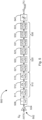
- FIG. 3 shows a diagram to illustrate possible frequency divisions with a frequency line 300 on which possible oscillation frequencies are plotted in Hz.
- a first frequency range 301 and a second frequency range 302 are shown as examples. These first and second frequency ranges 301 and 302 indicate ranges in which the detection and damping of a low-frequency oscillation is of interest. Such frequency ranges can vary depending on the electrical supply network or network section of an electrical supply network.
- 3 shows an example of a first, second and third partial frequency range 311, 312 and 313.
- the first two partial frequency ranges 311 and 312 cover the first frequency range 301 and all three partial frequency ranges 311 to 313 cover the second frequency range 302 .
- all three partial frequency ranges 311 to 313 can also be used to detect a low-frequency oscillation for the first range 301 . If a low-frequency oscillation is detected outside of the first region 301, it can be rejected or does not need to be considered any further.
- a time window with a length of 25 seconds and a resolution of 0.5 seconds is provided for the first partial frequency range 311 .
- a time window with a length of 12.5 seconds and a resolution of 0.25 seconds is provided for the second partial frequency range 312 .
- a time window with a length of 5 seconds and a resolution of 0.1 second is provided for the third partial frequency range 313 .
- FIG. 4 shows a damping control structure 400 for determining a desired damping signal for damping a low-frequency vibration.
- the damping control structure 400 has a signal input 402 at which the mains voltage or a mains signal exhibiting the low-frequency oscillations is input.
- the mains voltage can thus be recorded directly and entered there, i.e. a recorded mains signal.
- the mains voltage is recorded by detecting three phase-to-earth voltages of the three-phase system.
- a space vector is calculated from this and only the amplitude of this space vector is considered.
- the nominal voltage i.e. a fixed value, can be subtracted from the amplitude of this space vector. Only a difference between the amplitude of the space vector and the fixed mains voltage value then remains. This difference can be entered at the signal input 402 .
- This difference is therefore an input signal or mains signal that still has the low-frequency oscillations because only a constant value was subtracted.
- This input signal is then routed via the signal process block 404, which can carry out a first filtering in order to filter out measurement noise in particular.
- the signal process block 404 can thus have a low-pass behavior in particular.
- a pre-filtered or pre-processed signal S 1 is thus output at the output of the signal processing block 404 and input into one of the analysis blocks 411 to 413 .
- a network error can preferably be detected, for example a voltage dip. If a network fault is detected, a signal detected before the network fault or a signal or value representative thereof, such as an average value, can be used during the network fault instead of the detected or measured signal. This applies in particular to a very short network error in the range from 100 to 500 ms.
- the proposed damping of vibrations is usually important after a grid fault. The proposed bridging of the voltage dip during the measurement can ensure that the low-frequency oscillation is quickly and accurately recorded after the fault.
- each of the three analysis blocks carries out a frequency analysis for a partial frequency range.
- each of the three analysis blocks 411 to 413 has its own time window and its own resolution. This could be done, for example, for three different partial frequency ranges 311 to 313 with the corresponding window lengths and resolutions, as in 3 was explained.
- each of the three analysis blocks 411 to 413 can be an identified low-frequency oscillation. However, it is of course also possible that no low-frequency oscillation is present and therefore none can be detected. It is also conceivable that a plurality of low-frequency oscillations are detected in one or more of the analysis blocks.
- a low-frequency oscillation is detected in each of the three analysis blocks 411 to 413.
- the respective analysis block 411 to 413 outputs the frequency and amplitude and transfers these values to a coordination unit 406.
- These recognized low-frequency oscillations are evaluated in the coordination unit 406 .
- the target vibration One of the remaining low-frequency vibrations is identified as the target vibration and only this is then considered further. It is particularly important that the low-frequency vibration that has the greatest amplitude of all identified and relevant low-frequency vibrations is considered to be the target vibration. However, it is also possible to consider a different or further criterion. For example, a quotient of amplitude and oscillation frequency can be formed for each low-frequency oscillation, and the low-frequency oscillation with the largest quotient calculated here can be identified as the target oscillation, to name a further example.
- all three analysis blocks 411 to 413 which are also representative of a different number of analysis blocks, identify a total of only a single low-frequency oscillation, which then automatically forms the target oscillation.
- the oscillation frequency of the target oscillation identified in this way is output at frequency output 408 as oscillation frequency f PSOD of the low-frequency oscillation to be damped.
- This frequency f PSOD can be referred to as the damping frequency f PSOD for the sake of simplicity.
- This roll-off frequency f PSOD is then input to a bandpass filter block 410 .
- the bandpass filter block 410 is then adjusted according to the inputted attenuation frequency f PSOD , namely in particular such that the attenuation frequency f PSOD forms the bandpass filter frequency.
- the bandpass filter block 410 which is now set to the damping frequency f PSOD , can thus receive the pre-filtered signal S 1 as an input signal.
- the coordination unit 406 can output an initialization trigger Ti, which then namely has the value 1.
- the pre-filtered signal S 1 is multiplied by the initialization trigger Ti.
- the pre-filtered signal S 1 is thus passed through to the bandpass filter block 410 .
- the initialization trigger Ti can only assume the values 0 or 1. Before the initialization, the coordination unit 406 only outputs the value 0 as the initialization trigger Ti.
- the pre-filtered signal S 1 is then passed through the bandpass filter block 410 and of course it also has the low-frequency oscillation identified as dominant.
- the bandpass filter block 410 or the bandpass filter implemented therein is now precisely adapted to the dominant low-frequency oscillation to be damped, with the result that the pre-filtered signal S 1 , which initially still has all frequency components, now only the target vibration to be damped is passed through and everything else is filtered out.
- the bandpass filter block 410 therefore outputs the vibration signal Sd to be damped and transfers it to the determination controller block 416.
- the determination controller block 416 converts the vibration signal Sd to be damped into a desired damping signal Q PSOD .
- the determination controller block 416 can in particular change the amplitude and phase of the oscillation signal Sd to be damped and, if necessary, carry out further transformations such as filtering. Details on this are provided below figure 5 which basically shows the internal structure of the determination ruler block 416.
- the desired damping signal Q PSOD is to be superimposed on a further signal for damping, in order thereby to generate a desired feed signal which contains this desired damping signal. Details on this are described further below. First of all, however, it is provided that the amplitude of the desired damping signal Q PSOD generated by the determination controller block 416 can be increased slowly for activation, in particular from zero.
- An output multiplier 418 is provided for this purpose.
- the desired damping signal Q PSOD can be multiplied by a value in the output multiplier 418, which can rise from 0 to 1, for example as a ramp. Such a value can be output by the coordination unit 406 as an output trigger T A .
- This output trigger T A can also be output as output trigger T A in order to then be used as an activation indicator in subsequent control structures.
- the damping control structure 400 thus receives an input signal So, which is basically representative of the entire mains voltage signal, and depending on this, the damping control structure 400 outputs the damping setpoint signal Q PSOD in addition to the output trigger T A , which can act as an activation indicator.
- FIG. 12 shows a structure with reshaping elements, many of which may also be referred to as filters, that may be included in the determination controller block 416.
- FIG. The vibration signal Sd to be damped can be input at the converter input 502 of the converter structure 500 . It is possible that only the normalized differential voltage is entered here, for example as a percentage value related to the nominal voltage. The voltage difference is therefore, as explained above, the amplitude of the space vector calculated from the three voltage values of the three phases minus the value of the nominal voltage. The nominal voltage can correspond to 100%.
- This input signal can first be passed through an amplifier 504 in order to amplify it.
- a low-pass filter element 506 can follow, which can further reduce any remaining noise component.
- FIG. 5 shows three examples, each with three members. However, more or, in particular, fewer links can also be provided in each case.
- the elements are linear, they may be arranged in an order other than that shown. However, the proposed sequence can be advantageous if the calculation is not arbitrarily precise and signal reproduction is not arbitrarily precise.
- the low-pass filter element 506 is followed by a high-pass filter element 510, which is made up of three high-pass filter elements 511 to 513 here.
- the high-pass filter element 510 is provided for filtering out remaining low-frequency signal components from the oscillation signal to be damped. Such low-frequency signal components can occur particularly due to wind energy installations feeding in due to wind fluctuations.
- the low-pass filter element 506 and the high-pass filter element 510 are tuned to the roll-off frequency f PSOD . Therefore, this damping frequency f PSOD is entered into the determination controller block 416 and can thus be used in this converter structure 500 of the figure 5 are taken into account.
- the low-pass filter element 506, the high-pass filter element 510 and the lead-lag elements or lead-lag elements explained below can also be set as a function of the damping frequency f PSOD .
- the low-pass filter element 506 is set in such a way that its cut-off frequency is above the roll-off frequency fPSOD .
- the high-pass filter element 510 or the high-pass filter elements 511 to 513 are set in such a way that their cut-off frequency or cut-off frequencies is or are below the damping frequency f PSOD .
- the high-pass filter element 510 is followed by a first lead-lag filter element 520, which is constructed from three individual lead-lag filter elements 521 to 523.
- a higher selectivity can be achieved by using a plurality of filter elements, in this case the three lead-lag filter elements 521 to 523. This also applies to the high-pass filter element 510 and also to the second lead-lag filter element, which will be described below.
- a lead-lag filter can be used to achieve signal shifts that are frequency-dependent.
- the vibration signal to be damped in particular be shifted accordingly after the further filtering described, which further elaborates this vibration signal to be damped. This allows communication-related delay times to be compensated.
- a lead-lag filter which can also be referred to as a lead-lag element, can be implemented in that at least one filter element or filter element is designed as a lead element and another filter element or filter element as a lag filter or lag member is formed.
- a second lead-lag filter element 530 can be provided, which is also made up of three lead-lag filter elements 531 to 533 . It is also contemplated that the first lead-lag filter element 520 operates essentially as a lead element in the frequency range under consideration, whereas the second lead-lag filter element 530 operates essentially as a lag element in the frequency range under consideration.
- a limiting element 540 is also provided, with which the generated signal can be limited if necessary. This can prevent an undesirably high signal amplitude from occurring as a result of the processing with the various filter elements. Such an undesirably high signal amplitude can also occur when the vibration signal to be damped has a correspondingly high amplitude. Generating a corresponding desired damping signal, which also has a high amplitude, would be appropriate in principle, but can have problems in implementation, so that this limitation is provided.
- a desired damping signal ⁇ Q PSOD is thus output by the converter structure 500, which can also be output as a percentage value.
- a maximum reactive power value of the feed-in device can be used as a reference here, which can correspond to the nominal power of the feed-in device.
- the designation with the Greek letter ⁇ indicates that this desired damping signal is to be superimposed on an existing signal. In particular after multiplication at the output multiplier 418 by the activation trigger T A , it can correspond to the desired damping signal Q PSOD .
- a corresponding reactive power signal is determined as the desired damping signal, and the elements or members in determination controller block 416 or converter structure 500 are adapted to this.
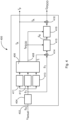
- Figures 6 to 8 show alternative structures for generating a feed target signal dependent on a base target signal and dependent on an attenuation target signal. All three structures of the Figures 6 to 8 build on a structure with a core controller 602, 702 or 802. Such a core controller is provided for converting a base target signal that does not yet have a target damping signal.
- This basic reactive power target signal Qs should be fed in as a feed signal, at least as long as no target attenuation signal is taken into account, and for this purpose the core controller generates a controller output signal Q A . Without taking into account the desired damping signal, this can correspond to a desired feed-in signal Q E .
- the core controller receives a control error e as an input signal (can also be referred to synonymously as a control deviation) as the result of a target/actual value comparison between the basic reactive power target signal Qs and a reactive power signal Qi actually fed in. Deviations between the basic reactive power setpoint signal Qs and the reactive power signal Qi actually fed in, i.e. the actual value, can result in particular from the behavior of the feed unit, i.e. in particular an inverter arrangement, and possibly other electrical components such as chokes, transformers and transmission lines.
- FIG 6 An overall structure 600 is presented, in which the target attenuation signal Q PSOD is applied to the base reactive power target signal Qs at a first summing element 604 .
- a modified base reactive power setpoint signal Qs′ results and, in addition to this, the control error e is formed at the second summing element 606 .
- the control error e is then input to the core controller 602 as before.
- the damping setpoint signal is generated by the damping controller 601, which essentially corresponds to the damping control structure 400 of FIG 4 can match.
- the attenuation controller 601 also receives an input signal So, which corresponds to the input signal So 4 can match.
- FIG. 6 thus shows a simple variant in which there is the problem that the previous core controller 602 also has to take this additional desired damping signal into account.
- a core controller 602 is often provided for the conversion of a substantially constant desired reactive power signal, that is to say a basic desired reactive power signal Q S , and is therefore not necessarily provided for correcting an oscillating desired signal.
- this core controller 602 is fast enough, that is to say it is designed fast enough and/or the vibration to be damped is slow enough or a correspondingly slow vibration to be damped is expected, the structure of the 6 be used.
- FIG. 7 shows an overall structure 700 in which the desired damping signal Q PSOD is applied to the controller output signal Q A downstream of the core controller 702 at a second summing element 706 . This directly results in the desired feed-in signal Q E .
- an attenuation controller 701 is provided, which essentially corresponds to the attenuation control structure 400 of FIG 4 can correspond and also can get the same input signal So.
- a first summing element 704 is also provided, which forms a control error e, namely from the difference between the base reactive power setpoint signal Qs and the fed-in reactive power actual value Qi.
- the control error e also includes an applied damping signal that is fed in superimposed on the desired damping signal.
- the desired damping signal Q PSOD By applying the desired damping signal Q PSOD to the second summing element 706, the reactive power fed in deviates from the basic desired reactive power signal Qs by this desired damping signal Q PSOD because of the modified desired feed signal Q E .
- the fed-in reactive power actual value Qi is changed accordingly as a result. This can lead to the core controller 702 attempting to correct this resulting, varying control error.
- the core controller 702 is sufficiently slow compared to the vibration signal Sd to be damped and thus compared to the desired damping signal Q PSOD , then this simple overall structure 700 can be suitable or at least sufficient.
- the overall structure 800 basically provides for the desired attenuation signal Q PSOD to be applied to the controller output signal Q A at a second summing element 806 in order to obtain the desired feed signal Q E in this way.
- the fed-in reactive power actual value Qi is made for the damping signal fed in according to the desired damping signal. In this way it can be achieved that the core controller 802 neither has to convert the desired damping signal nor is it influenced by it in the control error e.
- the actual reactive power signal Qi that is fed in is routed via a bandpass filter 810 .
- the bandpass filter 810 can correspond to the bandpass filter block 410 of the 4 and also receives the damping frequency f PSOD as an input value, namely from the damping controller 801, which can essentially correspond to the damping control structure 400.
- Bandpass filter 810 filters a compensation signal component from the recorded feed signal, ie from actual reactive power signal Qi.
- the compensation signal component corresponds, at least in terms of its frequency, to a damping signal Qd corresponding to the desired damping signal Q PSOD .
- damping signal Qd thus actually does not correspond exactly to the desired damping signal Q PSOD , so that the desired damping signal Q PSOD cannot simply be used for cleaning either.
- the compensation signal component generated in this way is subtracted as an attenuation compensation signal in a third summing element 808 from the reactive power actual signal Qi.
- a reactive power signal that has been corrected for the damping signal Qd remains, which is subtracted from the base reactive power target signal Qs in the first summing element 804 in order to form the control error e, which has accordingly been corrected for the damping signal Qd.
- the generation or output of the desired damping signal Q PSOD depends on the initialization trigger Ti and the activation trigger T A .
- This initialization or activation is thus also implemented in the overall structure 800 by an input multiplier 814 and an output multiplier 818 .
- the correction of the reactive power actual signal Qi at the third summing element 808 is not active even if no nominal damping signal Q PSOD is generated or output.
Abstract
Verfahren zum Dämpfen niederfrequenter Schwingungen in einem elektrischen Versorgungsnetz mittels einer in das elektrische Versorgungsnetz einspeisenden Einspeiseeinrichtung, insbesondere Windenergieanlage, wobei das elektrische Versorgungsnetz eine Netzspannung und eine Netzfrequenz aufweist, umfassend die Schritte: Aufnehmen eines die niederfrequenten Schwingungen aufweisenden Netzsignals, Aufteilen eines Gesamtfrequenzbereichs des Netzsignals, in dem zu dämpfende Schwingungen zu erwarten sind, in mehrere Teilfrequenzbereiche, jeweils mit einer unteren und einer oberen Bereichsfrequenz, Durchführen jeweils einer Frequenzanalyse des Netzsignals für jeden Teilfrequenzbereich, um jeweils eine oder mehrere Schwingungen mit einer in dem Teilfrequenzbereich liegenden Schwingungsfrequenz zu identifizieren, sofern vorhanden, in Abhängigkeit von den Frequenzanalysen aller Teilfrequenzbereiche Identifizieren einer zu dämpfenden niederfrequenten Schwingung als Zielschwingung, Erfassen der Zielschwingung wenigstens nach Frequenz und Amplitude und optional nach Phase, Bestimmen eines Dämpfungssollsignals in Abhängigkeit von der nach Frequenz und Amplitude und ggf. Phase erfassten Zielschwingung zum Dämpfen der erfassten Zielschwingung, Erzeugen eines Einspeisesollsignals in Abhängigkeit von dem Dämpfungssollsignal und einem Basissollsignal und Erzeugen und Einspeisen eines Einspeisesignals in Abhängigkeit von dem Einspeisesollsignals (QE).Method for damping low-frequency oscillations in an electrical supply network by means of a feed device, in particular a wind turbine, feeding into the electrical supply network, the electrical supply network having a network voltage and a network frequency, comprising the steps: recording a network signal having the low-frequency oscillations, dividing an overall frequency range of the network signal, in which vibrations to be damped are to be expected, into several sub-frequency ranges, each with a lower and an upper range frequency, carrying out a frequency analysis of the network signal for each sub-frequency range in order to identify one or more vibrations with an oscillation frequency in the sub-frequency range, if any , depending on the frequency analyzes of all partial frequency ranges, identifying a low-frequency vibration to be damped as a target vibration, recording the target vibration at least according to frequency and amplitude and optionally according to phase, determining a damping target signal depending on the target vibration recorded according to frequency and amplitude and, if necessary, phase, for damping the detected target vibration, generating a target injection signal dependent on the target damping signal and a base target signal, and generating and injecting an injection signal dependent on the target injection signal (QE).
Description
Die vorliegende Erfindung betrifft ein Verfahren zum Dämpfen niederfrequenter Schwingungen in einem elektrischen Versorgungsnetz mittels einer in das elektrische Versorgungsnetz einspeisenden Einspeiseeinrichtung, insbesondere mittels einer Windenergieanlage. Außerdem betrifft die vorliegende Erfindung eine entsprechende Windenergieanlage.The present invention relates to a method for damping low-frequency oscillations in an electrical supply network by means of a feed device that feeds into the electrical supply network, in particular by means of a wind turbine. In addition, the present invention relates to a corresponding wind energy installation.
Windenergieanlagen sind bekannt, sie speisen elektrische Leistung in ein elektrisches Versorgungsnetz ein und werden häufig auch zum Stützen des elektrischen Versorgungsnetzes eingesetzt. So ist es bspw. bekannt, Blindleistung in Abhängigkeit von der Netzspannung des elektrischen Versorgungsnetzes einzuspeisen. Insbesondere wird dabei eine Abweichung der Netzspannung von einer Netznennspannung betrachtet und abhängig davon wird Blindleistung eingespeist, was durch Veränderung des Phasenwinkels des einspeisenden Stroms realisiert werden kann. Ein solches Verfahren ist aus dem Dokument
Darüber hinaus können im elektrischen Versorgungsnetz sog. subsynchrone Schwingungen auftreten. Diese können sich als Schwankungen der Spannungsamplituden bemerkbar machen. Solche Schwankungen können Frequenzen unterhalb der Netznennfrequenz aufweisen, insbesondere im Bereich von wenigen Hertz oder sogar mit Frequenzen unter 1 Hz. Besonders werden hier elektromechanische Schwingungen betrachtet, nämlich mechanische Schwingungen konventioneller Kraftwerke, die infolge einer Störung auftreten und zu elektrischen Schwingungen im Netz führen, die eine Reaktion anderer Teilnehmer hervorrufen Das sind im Wesentlichen langsame Schwingungen im Bereich von 0,1 Hz-1,5 Hz, die hier betrachtet werden. Das sind besonders Inter-Area-Schwingungen, die entsprechend langsam sind, nämlich meist unter 1 Hz, selten bis 1,5 Hz, oder in einer Ausnahme 1,8 Hz erreichen können.In addition, so-called subsynchronous oscillations can occur in the electrical supply network. These can become noticeable as fluctuations in the voltage amplitudes. Such fluctuations can have frequencies below the nominal grid frequency, especially in the range of a few Hertz or even with frequencies below 1 Hz cause electrical oscillations in the network that cause other participants to react. These are essentially slow oscillations in the range of 0.1 Hz-1.5 Hz that are considered here. These are particularly inter-area vibrations, which are correspondingly slow, i.e. mostly below 1 Hz, rarely up to 1.5 Hz, or in one exception can reach 1.8 Hz.
Ein Problem solcher subsynchronen Schwingungen ist, dass sie schwer zu erfassen sind. Eine Möglichkeit der Erfassung besteht durch Verwendung einer Fast-Fourier-Transformation, was aus dem Dokument
Eine solche Erfassung ist vorgeschlagen worden für die Überprüfung auf das Vorliegen zumindest einer subsynchronen Schwingung über ein Frequenzspektrum, das über mehrere Zehnerpotenzen reichen kann. Die Erfassung einer subsynchronen Schwingung ist mit einem solchen Verfahren grundsätzlich möglich, das Verfahren kann aber für eine Implementierung, die auch eine Dämpfung solcher subsynchronen Schwingungen vorsieht, Nachteile aufweisen.Such a detection has been proposed for checking for the presence of at least one subsynchronous oscillation over a frequency spectrum that can range over several orders of magnitude. In principle, it is possible to detect a subsynchronous oscillation with such a method, but the method can have disadvantages for an implementation that also provides for damping of such subsynchronous oscillations.
Besonders ist für die Erfassung, um darauf basierend eine Dämpfung vorzusehen, oftmals eine höhere Güte der Erfassung erforderlich, ohne dass aber ein so großes Frequenzspektrum abgedeckt werden muss. Besonders kommt in Betracht, dass nicht jede Frequenz, in der eine subsynchrone Schwingung auftreten kann, auch störend sein muss. Stattdessen kann eine Dämpfung subsynchroner Schwingungen oftmals nur in einem eng vorgegebenen Frequenzbereich erforderlich sein.In particular, a higher quality of the detection is often required for the detection in order to provide an attenuation based thereon, but without such a large frequency spectrum having to be covered. It is particularly important that not every frequency in which a subsynchronous oscillation can occur must also be disruptive. Instead, damping of subsynchronous vibrations can often only be necessary in a narrowly specified frequency range.
Darüber hinaus kann das Dämpfen subsynchroner Schwingungen durch Einspeisung von Blindleistung durchgeführt werden. Eine solche dämpfende Blindleistungseinspeisung kann mit einer oben genannten spannungsabhängigen Blindleistungseinspeisung ggf. kollidieren. So kommt in Betracht, dass eine spannungsabhängige Blindleistungseinspeisung gegen eine Blindleistungseinspeisung arbeitet, die subsynchrone Schwingungen dämpfen soll.In addition, the damping of subsynchronous oscillations can be carried out by injecting reactive power. Such a damping reactive power feed can possibly collide with an above-mentioned voltage-dependent reactive power feed. It is therefore possible for a voltage-dependent reactive power feed to work against a reactive power feed that is intended to dampen subsynchronous oscillations.
Der vorliegenden Erfindung liegt somit die Aufgabe zu Grunde, zumindest eines der vorstehend genannten Probleme zu adressieren. Insbesondere soll eine Lösung vorgeschlagen werden, bei der subsynchrone Schwingungen in einem relevanten Frequenzbereich erkannt und gedämpft werden, insbesondere mit möglichst wenig Einfluss auf andere netzstützende Einspeisungen. Zumindest soll zu bisher bekannten Lösungen eine alternative Lösung vorgeschlagen werden.The present invention is therefore based on the object of addressing at least one of the problems mentioned above. In particular, a solution is to be proposed in which subsynchronous oscillations in a relevant frequency range are recognized and dampened, in particular with as little influence as possible on other grid-supporting feeds. At the very least, an alternative solution to previously known solutions should be proposed.
Erfindungsgemäß wird ein Verfahren gemäß Anspruch 1 vorgeschlagen. Ein solches Verfahren betrifft somit das Dämpfen niederfrequenter Schwingungen in einem elektrischenAccording to the invention a method according to
Versorgungsnetz mittels einer in das elektrische Versorgungsnetz einspeisenden Einspeiseeinrichtung. Eine solche Einspeiseeinrichtung kann insbesondere eine Windenergieanlage sein. Es kommen aber auch andere dezentrale Einspeiseeinrichtungen in Betracht, z.B. eine Einspeisung aus einem Energiespeicher, aus dem mittels eine Frequenzumrichters eingespeist wird. Es kommt auch eine Einspeisung aus anderen Energiequellen in Betracht. Für direkt gekoppelte Synchrongeneratoren ist das Verfahren grundsätzlich nicht geeignet. Die einspeisenden Einspeiseeinrichtungen, die hier verwendet werden können, sind somit insbesondere umrichtergeführte Einspeiseeinrichtungen. Insbesondere sog. Vollumrichterkonzepte werden vorgeschlagen, bei denen die gesamte eingespeiste Leistung durch eine Umrichteranordnung geführt wird, sodass die gesamte eingespeiste Leistung durch die Umrichteranordnung in Amplitude, Frequenz und Phase gesteuert werden kann.Supply network by means of a feed device that feeds into the electrical supply network. Such a feed device can in particular be a wind energy plant. However, other decentralized feed-in devices can also be considered, e.g. feed from an energy store, from which a frequency converter is used to feed. Feeding in from other energy sources is also possible. In principle, the method is not suitable for directly coupled synchronous generators. The infeed devices that can be used here are therefore, in particular, converter-controlled infeed devices. In particular, so-called full converter concepts are proposed in which the entire power fed in is routed through a converter arrangement, so that the entire power fed in can be controlled by the converter arrangement in terms of amplitude, frequency and phase.
Es wird von einem elektrischen Versorgungsnetz ausgegangen, dass eine Netzfrequenz aufweist, insbesondere übliche 50Hz oder 60Hz. Gemäß einem Schritt wird vorgeschlagen, ein die niederfrequenten Schwingungen aufweisendes Netzsignal aufzunehmen. Insbesondere wird hier eine Netzspannung erfasst. Natürlich kann es auch vorkommen, dass sich herausstellt, dass gar keine niederfrequenten Schwingungen vorliegen. Potentiell weist dieses Netzsignal aber die niederfrequenten Schwingungen, oder zumindest eine, auf.An electrical supply network is assumed that has a network frequency, in particular the usual 50 Hz or 60 Hz. According to one step, it is proposed to record a network signal that has the low-frequency oscillations. In particular, a mains voltage is detected here. Of course, it can also happen that it turns out that there are no low-frequency vibrations at all. However, this network signal potentially exhibits the low-frequency oscillations, or at least one.
Es wird dann ein Aufteilen eines Gesamtfrequenzbereiches des Netzsignals, in dem zu dämpfende Schwingungen zu erwarten sind, in mehrere Teilfrequenzbereiche vorgeschlagen. Jeder Teilfrequenzbereich weist eine untere, obere und mittlere Bereichsfrequenz auf. Sind bspw. zu dämpfende Schwingungen in einem Frequenzbereich von 1-5Hz zu erwarten, so kann ein Teilfrequenzbereich von 1Hz bis 3Hz reichen und damit 1Hz, 2Hz und 3Hz als untere, mittlere und obere Bereichsfrequenz aufweisen. Ein weiterer Teilfrequenzbereich kann von 2Hz bis 4Hz reichen und damit 2Hz, 3Hz und 4Hz als untere, mittlere und obere Bereichsfrequenz aufweisen. Ein dritter Teilfrequenzbereich kann von 3Hz bis 5Hz reichen und entsprechend 3Hz, 4Hz und 5Hz als untere, mittlere und obere Bereichsfrequenz aufweisen.It is then proposed to divide an overall frequency range of the network signal, in which vibrations to be damped are to be expected, into a number of partial frequency ranges. Each sub-frequency range has a low, high, and middle range frequency. If, for example, vibrations to be damped are to be expected in a frequency range of 1-5Hz, a partial frequency range can range from 1Hz to 3Hz and thus have 1Hz, 2Hz and 3Hz as the lower, middle and upper frequency range. Another partial frequency range can range from 2Hz to 4Hz and thus have 2Hz, 3Hz and 4Hz as the lower, middle and upper frequency range. A third sub-frequency range can range from 3Hz to 5Hz and have 3Hz, 4Hz and 5Hz as the lower, middle and upper range frequencies accordingly.
An diesem Beispiel ist zu erkennen, dass die Teilfrequenzbereiche sich auch überschneiden können, sie müssen sich aber nicht überschneiden oder können sich auch im geringeren Maße überschneiden.This example shows that the partial frequency ranges can also overlap, but they do not have to overlap or can also overlap to a lesser extent.
Die mittlere Bereichsfrequenz kann als arithmetisches Mittel der unteren und oberen Bereichsfrequenz gewählt werden.The center range frequency can be chosen as the arithmetic mean of the low and high range frequencies.
Es wird dann vorgeschlagen, jeweils eine Frequenzanalyse des Netzsignals für jeden Teilfrequenzbereich durchzuführen, um jeweils eine oder mehrere Schwingungen mit einer in dem Teilfrequenzbereich liegenden Schwingungsfrequenz zu identifizieren, sofern vorhanden.It is then proposed to carry out a frequency analysis of the network signal for each partial frequency range in order to identify one or more oscillations with an oscillation frequency lying in the partial frequency range, if any.
Es werden also alle Teilfrequenzbereiche einzeln auf eine oder mehrere Schwingungsfrequenzen untersucht. In diesem Stadium ist häufig noch nicht bekannt, ob überhaupt eine Schwingung in dem jeweiligen Teilfrequenzbereich zu erwarten ist, und daher auch nicht bei welcher Frequenz oder Amplitude sie zu erwarten ist.All partial frequency ranges are therefore individually examined for one or more vibration frequencies. At this stage it is often not yet known whether an oscillation is to be expected in the respective partial frequency range at all, and therefore also not at what frequency or amplitude it is to be expected.
Sind nun alle Teilfrequenzbereiche in diesem Sinne untersucht worden, sind also alle in diesen Teilfrequenzbereichen aufgetretenen Schwingungen mit ihren Schwingfrequenzen identifiziert worden, erfolgt eine Gesamtbetrachtung.If all partial frequency ranges have now been examined in this way, i.e. if all vibrations that have occurred in these partial frequency ranges have been identified with their vibration frequencies, an overall assessment follows.
Dafür wird vorgeschlagen, in Abhängigkeit von den Frequenzanalysen aller Teilfrequenzbereiche eine zu dämpfende niederfrequente Schwingung als Zielschwingung zu identifizieren. Hier wurde besonders erkannt, dass mehrere Schwingungen mit unterschiedlichen Schwingungsfrequenzen identifiziert werden können, es aber nicht unbedingt zweckmäßig und/oder möglich ist, all diese Schwingfrequenzen zu dämpfen. Hier kommt insbesondere in Betracht, eine Zielschwingung nach der Amplitude der identifizierten Schwingungen auszuwählen. Außerdem ist eine vorgeschlagene Ausgestaltung, eine mögliche Zielschwingung nur aus Schwingungen mit solchen Schwingfrequenzen auszusuchen, die auch gedämpft werden sollen.For this purpose, it is proposed to identify a low-frequency vibration to be damped as a target vibration, depending on the frequency analyzes of all partial frequency ranges. It was particularly recognized here that a number of vibrations with different vibration frequencies can be identified, but it is not necessarily expedient and/or possible to dampen all of these vibration frequencies. Here, in particular, it is possible to select a target vibration based on the amplitude of the identified vibrations. In addition, a proposed embodiment is to select a possible target oscillation only from oscillations with oscillation frequencies that are also to be damped.
Es kommt insbesondere in Betracht, dass ein Frequenzbereich, in dem Schwingungen gedämpft werden sollen, falls sie auftreten, kleiner ist als der insgesamt untersuchte Frequenzbereich. Insbesondere kann bereits das Festlegen des Gesamtfrequenzbereichs so erfolgen, dass dieser über einen solchen Frequenzbereich, in dem Schwingungen gedämpft werden sollen, hinausgeht. Ein Grund kann darin liegen, dass relevante Frequenzen möglicherweise am Rande des Gesamtfrequenzbereichs, insbesondere am Rande eines Teilfrequenzbereichs nicht mehr optimal identifiziert werden können.In particular, it is considered that a frequency range in which vibrations are to be damped, if they occur, is smaller than the frequency range examined overall. In particular, the overall frequency range can already be defined in such a way that it goes beyond such a frequency range in which oscillations are to be damped. One reason may be that relevant frequencies can no longer be optimally identified at the edge of the overall frequency range, in particular at the edge of a partial frequency range.
Grundsätzlich ist allerdings auch nicht ausgeschlossen, mehr als nur eine zu dämpfende niederfrequente Schwingung als Zielschwingung zu identifizieren. Es wurde aber erkannt, dass häufig nur eine relevante Zielschwingung zu erwarten ist und es ist von Vorteil, sowohl das Erfassen als auch das sich anschließende Dämpfen auf diese Zielschwingung zu konzentrieren.In principle, however, it is also possible to identify more than just one low-frequency vibration to be damped as a target vibration. However, it was recognized that often only one relevant target oscillation is to be expected and it is advantageous to concentrate both the detection and the subsequent damping on this target oscillation.
Nachdem also eine Zielschwingung identifiziert wurde, wird diese wenigstens nach Frequenz und Amplitude erfasst. Das Identifizieren der zu dämpfenden niederfrequentenSo after a target vibration has been identified, it is recorded at least according to frequency and amplitude. Identifying the low-frequency ones to be attenuated
Schwingung als Zielschwingung kann bereits das Identifizieren ihrer Frequenz beinhalten. Das kann aber noch ein ungenaues Identifizieren der Frequenz dieser Zielschwingung bedeuten. Dazu wird dann vorgeschlagen, die Zielschwingung nach Frequenz und Amplitude jeweils möglichst genau zu erfassen. Optional kann zusätzlich eine Phase, also Phasenlage der Zielschwingung erfasst werden. Das kann für die durchzuführende Dämpfung hilfreich sein, ist aber nicht unbedingt notwendig, wie nachfolgend noch erkennbar wird.Vibration as a target vibration can already include identifying its frequency. However, this can still mean an inaccurate identification of the frequency of this target vibration. To this end, it is then proposed to record the target vibration according to frequency and amplitude as precisely as possible. Optionally, a phase, i.e. the phase position of the target oscillation, can also be recorded. This can be helpful for the damping to be carried out, but is not absolutely necessary, as will be seen below.
Weiter wird vorgeschlagen, ein Dämpfungssollsignal in Abhängigkeit von der nach Frequenz und Amplitude und ggf. auch Phase erfassten Zielschwingung zu bestimmen, um die erfasste Zielschwingung zu dämpfen. Ein solches Dämpfungssollsignal weist insbesondere selbst die Frequenz der Zielschwingung auf. Das Einstellen einer Phase des Dämpfungssollsignals ist auch vorteilhaft, um dann ein entsprechendes Dämpfungssignal gemäß dem Dämpfungssollsignal zu erzeugen, das die Zielschwingung auch dämpft und nicht bei falscher Phasenlage anregt. Eine solche Phasenlage des Dämpfungssollsignals und damit dann auch des Dämpfungssignals muss aber nicht unbedingt unmittelbar von einer Phase der erfassten Zielschwingung abhängig eingestellt werden. Stattdessen kann auch, was später noch im Detail beschrieben wird, die erfasste Zielschwingung bzw. ein davon abgeleitetes Signal anderweitig die Phasenlage des Dämpfungssollsignals und damit des Dämpfungssignals beeinflussen. In der Tat ist aber eine Option, dafür die Phase der Zielschwingung zu erfassen und davon abhängig die Phase des Dämpfungssollsignals zu bestimmen.It is also proposed to determine a target damping signal as a function of the target vibration detected according to frequency and amplitude and possibly also phase, in order to dampen the detected target vibration. In particular, such a desired damping signal itself has the frequency of the target oscillation. Setting a phase of the desired damping signal is also advantageous in order to then generate a corresponding damping signal according to the desired damping signal, which also damps the target oscillation and does not excite it if the phase position is incorrect. However, such a phase position of the desired damping signal and thus also of the damping signal does not necessarily have to be set as a direct function of a phase of the detected target oscillation. Instead, as will be described later in detail, the detected target oscillation or a signal derived from it can otherwise influence the phase position of the damping setpoint signal and thus the damping signal. In fact, one option is to record the phase of the target vibration and to determine the phase of the damping setpoint signal based on this.
Allerdings muss ein solches Dämpfungssollsignal nicht unbedingt ein sinusförmiges Signal sein, eine Variante ist aber, dass das Dämpfungssollsignal sinusförmig ist.However, such a desired damping signal does not necessarily have to be a sinusoidal signal, but one variant is that the desired damping signal is sinusoidal.
Es wird dann vorgeschlagen, ein Einspeisesollsignal in Abhängigkeit von dem Dämpfungssollsignal und in Abhängigkeit von einem Basissollsignal zu erzeugen. Das Einspeisesollsignal ist also eine Vorgabe für ein Einspeisesignal, das insbesondere eine einzuspeisende Blindleistung sein kann, aber auch eine Wirkleistung sein kann, oder beinhalten kann. Das Einspeisesignal soll die Dämpfung umsetzen, aber es können noch weitere Aufgaben für das Einspeisesignal existieren, z.B. eine Spannung zu stützen. Diese weiteren Aufgaben, oder nur eine weitere Aufgabe, werden durch das Basissollsignal vorgegeben. Die vorgesehene Dämpfung und die weiteren Aufgaben werden also in dem Einspeisesollsignal und dann dem Einspeisesignal zusammen berücksichtigt. Das Einspeisesollsignal setzt sich dann insbesondere aus dem Dämpfungssollsignal und dem Basissollsignal zusammen.It is then proposed to generate a desired feed signal as a function of the desired damping signal and as a function of a basic desired signal. The desired feed-in signal is therefore a specification for a feed-in signal, which can in particular be reactive power to be fed in, but can also be or contain active power. The injection signal is supposed to implement the damping, but there can be other tasks for the injection signal, e.g. to support a voltage. These additional tasks, or just one additional task, are specified by the base target signal. The intended damping and the other tasks are therefore taken into account together in the desired feed signal and then in the feed signal. The desired feed signal is then composed in particular of the desired damping signal and the basic desired signal.
Eine Möglichkeit ist, dass das Dämpfungssollsignal oder ein Teil davon, auf das Basissollsignal zum Erzeugen des Einspeisesollsignals aufzuschalten. Das Einspeisesignal setzt sich dann also aus einem Basissignal und dem Dämpfungssignal zusammen. Dafür sind jeweils Sollsignale vorgesehen, also das Einspeisesollsignal für das Einspeisesignal, das Basissollsignal für das Basissignal und das Dämpfungssollsignal für das Dämpfungssignal.One possibility is that the desired damping signal or a part thereof is superimposed on the basic desired signal for generating the desired feed signal. The feed signal is then made up of a base signal and the damping signal. are for each target signals provided, so the feed target signal for the feed signal, the base target signal for the base signal and the attenuation target signal for the attenuation signal.
Schließlich erfolgt das Erzeugen und Einspeisen des Einspeisesignals in Abhängigkeit von dem Einspeisesollsignals. Das kann mit Hilfe einer Umrichteranordnung durchgeführt werden.Finally, the feed signal is generated and fed in as a function of the desired feed signal. This can be done with the help of a converter arrangement.
Besonders kann das Dämpfungssignal eine Blindleistung bzw. ein Blindstrom sein. Zusätzlich kann bereits das Einspeisen einer Blindleistung bzw. eines Blindstroms als Basissignal vorgesehen sein. Hier kommt in Betracht, dass bereits eine spannungsabhängige Blindleistungseinspeisung implementiert ist. Eine solche spannungsabhängige Blindleistungseinspeisung liefert im Wesentlichen eine konstante Blindleistung bzw. einen konstanten Blindstrom, wenn die Netzspannung im Wesentlichen konstant ist. Eine solche spannungsabhängige Blindleistungseinspeisung reagiert, je nach Regelungsgeschwindigkeit, grundsätzlich auf niederfrequente Schwingungen, die dem Basisspannungssignal überlagert sind, mit einer Reaktion, die sogar zu einer Verschlechterung, insbesondere Anregung der Schwingung führen kann.In particular, the damping signal can be a reactive power or a reactive current. In addition, the feeding in of a reactive power or a reactive current can already be provided as a base signal. Here it is possible that a voltage-dependent reactive power feed is already implemented. Such a voltage-dependent reactive power feed essentially supplies a constant reactive power or a constant reactive current when the mains voltage is essentially constant. Depending on the control speed, such a voltage-dependent reactive power feed basically reacts to low-frequency oscillations that are superimposed on the base voltage signal, with a reaction that can even lead to a deterioration, in particular excitation of the oscillation.
Genau solche niederfrequenten Schwingungen, oder eine davon, werden nun aber erfasst und insbesondere eine Zielschwingung davon identifiziert. Diese hat meist eine vergleichsweise geringe Amplitude bzw. eine geringe Schwingungsamplitude. Gleichwohl ist es relevant sie zu dämpfen, bevor ihre Amplitude größer wird.Precisely such low-frequency vibrations, or one of them, are now detected and, in particular, a target vibration identified. This usually has a comparatively low amplitude or a low vibration amplitude. However, it is relevant to dampen them before their amplitude increases.
Dafür wird das Dämpfungssollsignal erfasst und auf das Basissollsignal aufgeschaltet. Die Amplitude der Zielschwingung mag im Vergleich zur Amplitude der Netzspannung gering sein, die Netzspannung mag also eine geringe Schwankungshöhe haben, das abgeleitete Dämpfungssollsignal kann aber eine signifikante Amplitude haben, die in der Größenordnung des Basissollsignals liegen kann, oder darüber. Natürlich kann sie auch geringer sein, was auch davon abhängt, wie groß jeweils eine solche spannungsabhängig eingespeiste Blindleistung ist, um bei diesem Beispiel zu bleiben.For this purpose, the desired damping signal is recorded and switched to the basic desired signal. The amplitude of the target oscillation may be small compared to the amplitude of the mains voltage, so the mains voltage may have a small amount of variation, but the derived damping target signal may have a significant amplitude, which may be of the order of the base target signal or greater. Of course, it can also be lower, which also depends on how large such a voltage-dependent reactive power is in each case, to stay with this example.
Entsprechend wird durch diese Überlagerung ein Einspeisesollsignal bzw. Einspeisesignal geschaffen oder es wird vorgeschlagen, das Einspeisesignal in Abhängigkeit von dem Einspeisesollsignal zu erzeugen und einzuspeisen.Correspondingly, this superimposition creates a desired feed signal or feed signal, or it is proposed to generate and feed the feed signal as a function of the desired feed signal.
Dadurch kann dann ein Einspeisesignal erzeugt und gesteuert werden, das das Dämpfungssignal beinhaltet und auch ein bereits vorhandenes Basissignal. Insbesondere kann ein dämpfendes Blindleistungssignal bzw. Blindstromsignal auf eine spannungsabhängige Blindleistungseinspeisung bzw. Blindstromeinspeisung abgestimmt werden. Diese gemeinsame Betrachtung verhindert, dass das Dämpfungssignal und das spannungsabhängig erzeugte Basissignal gegeneinander arbeiten.As a result, a feed signal can then be generated and controlled, which contains the damping signal and also an already existing base signal. In particular, a damping reactive power signal or reactive current signal on a voltage-dependent Reactive power feed or reactive current feed can be coordinated. This joint consideration prevents the damping signal and the voltage-dependent generated base signal from working against each other.
Gemäß einem Aspekt wird vorgeschlagen, dass das Dämpfungssollsignal eine einzuspeisende Blindleistung beschreibt und insbesondere das Basissollsignal durch Blindleistungssteuerung als Sollsignal für eine einzuspeisende Blindleistung vorgegeben wird. Die Blindleistungssteuerung kann bspw. einen fest vorgegebenen Blindleistungssollwert umsetzen, es kommt aber auch eine netzspannungsabhängige Blindleistungseinspeisung in Betracht. Damit setzt sich dann also auch das Einspeisesignal aus der Blindleistung gemäß Dämpfungssollsignal und aus der Blindleistung gemäß Basissollsignal zusammen.According to one aspect, it is proposed that the desired damping signal describes a reactive power to be fed in and, in particular, that the basic desired signal is specified by reactive power control as a desired signal for a reactive power to be fed in. The reactive power control can, for example, implement a permanently specified reactive power target value, but grid-voltage-dependent reactive power feed-in can also be considered. The feed-in signal is then also made up of the reactive power according to the desired damping signal and the reactive power according to the basic desired signal.
Hier wurde besonders erkannt, dass die Dämpfung der niederfrequenten Schwingung, oder ggf. mehrerer niederfrequenter Schwingungen mittels eines entsprechenden Blindleistungssignals erfolgt. Damit kann besonders einer Spannungsschwingung entgegengewirkt werden. Es wird vermieden, dass die eingespeiste Wirkleistung variiert wird und dadurch werden mechanische Belastungen der Windenergieanlage durch variierende Wirkleistungsbereitstellung vermieden. Besonders kann eine schwingende Wirkleistungsveränderung zu entsprechend schwingenden mechanischen Belastungen des Generators kommen, die auch auf weitere Teile der Windenergieanlage übertragen werden können. So kann es bspw. zu Schwingungen des Turms kommen, was hierdurch vermieden wird.Here it was recognized in particular that the damping of the low-frequency oscillation, or possibly a plurality of low-frequency oscillations, takes place by means of a corresponding reactive power signal. In this way, a voltage oscillation in particular can be counteracted. It is avoided that the active power that is fed in is varied, and as a result, mechanical stresses on the wind energy plant due to the varying provision of active power are avoided. In particular, an oscillating change in active power can lead to correspondingly oscillating mechanical loads on the generator, which can also be transferred to other parts of the wind energy installation. For example, the tower can vibrate, which is avoided in this way.
Gemäß einem Aspekt wird vorgeschlagen, dass zum Erzeugen des Einspeisesollsignals ein Kernregler vorgesehen ist, der in Abhängigkeit von dem Basissollsignal und dem eingespeisten Einspeisesignal ein Reglerausgangssignal ausgibt, und dass das Einspeisesollsignal in Abhängigkeit von dem Reglerausgangssignal bestimmt wird.According to one aspect, it is proposed that a core controller is provided to generate the desired feed signal, which outputs a controller output signal as a function of the basic desired signal and the fed-in signal, and that the desired feed signal is determined as a function of the controller output signal.
Dazu wird noch vorgeschlagen, dass das Dämpfungssollsignal oder ein Teil davon auf das Basissollsignal aufgeschaltet wird, und dadurch vom Kernregler berücksichtigt wird. Ergänzend oder alternativ wird vorgeschlagen, dass das Dämpfungssollsignal oder ein Teil davon auf das Reglerausgangssignal aufgeschaltet wird, und dadurch das Einspeisesollsignal beeinflusst.In addition, it is also proposed that the desired damping signal or part of it be superimposed on the basic desired signal and thus be taken into account by the core controller. In addition or as an alternative, it is proposed that the desired damping signal or a part thereof is applied to the controller output signal and thereby influences the desired feed signal.
Es ist also ein Kernregler vorgesehen, der synonym auch als innerer Regler oder innerer Regelkreis bezeichnet werden kann. Dieser Kernregler gibt ein Reglerausgangssignal in Abhängigkeit von dem Basissollsignal und dem eingespeisten Einspeisesignal aus. Insbesondere wird ein Soll-/Istwert-Vergleich zwischen Basissollsignal und dem eingespeisten Einspeisesignal gebildet und dieser Soll-/Istwert-Vergleich, also der resultierende Regelfehler, bildet somit das Eingangssignal des Kernreglers. Das ausgegebene Reglerausgangssignal bildet dann die Basis für das Einspeisesollsignal. Im einfachsten Fall entspricht das Einspeisesollsignal dem Reglerausgangssignal.A core controller is therefore provided, which can also be referred to synonymously as an inner controller or inner control loop. This core controller emits a controller output signal as a function of the basic setpoint signal and the feed signal that is fed in. In particular, a setpoint/actual value comparison is formed between the basic setpoint signal and the feed-in signal that is fed in, and this setpoint/actual value comparison, i.e. the resulting control error, thus forms the input signal of the core controller. The controller output signal then forms the basis for the feed setpoint signal. In the simplest case, the feed setpoint signal corresponds to the controller output signal.
Bei dem Aspekt, bei dem auf das Reglerausgangssignal das Dämpfungssollsignal oder ein Teil davon aufgeschaltet wird, ergibt sich das Einspeisesollsignal somit als Summe aus dem Reglerausgangssignal und dem Dämpfungssollsignal oder dem Teil davon, der aufgeschaltet wird. Das schließt natürlich nicht aus, dass etwaige andere ergänzende Regelsignale hinzu kommen. In der einfachsten und bevorzugten Ausführungsform ergibt sich das Einspeisesollsignal hier aber ausschließlich aus dem Reglerausgangssignal und dem aufaddierten Dämpfungssollsignal. Da das Dämpfungssollsignal insbesondere ein sinusförmiges Signal sein kann, kann es je nach Phasenlage natürlich auch abgezogen werden.In the aspect in which the desired damping signal or a part thereof is superimposed on the controller output signal, the desired feed signal is thus the sum of the controller output signal and the desired damping signal or the part thereof that is superimposed. Of course, this does not rule out the possibility of any other supplementary control signals being added. In the simplest and preferred embodiment, however, the desired feed signal results here exclusively from the controller output signal and the added damping desired signal. Since the desired damping signal can be a sinusoidal signal in particular, it can of course also be subtracted depending on the phase position.
Auch bei diesen Aspekten ist insbesondere vorgesehen, dass das Basissollsignal, das Dämpfungssollsignal und entsprechend auch das resultierende Einspeisesollsignal jeweils ein Sollsignal für eine Blindleistung sind.In these aspects, too, provision is made in particular for the base setpoint signal, the setpoint attenuation signal and, correspondingly, also the resulting setpoint feed signal to be a setpoint signal for a reactive power in each case.
So kann das Basissollsignal ein Blindleistungssollsignal sein, das eine spannungsabhängige Blindleistungssteuerung ausgegeben oder vorgegeben hat. Dieses Basissollsignal, das insbesondere auch bei deaktivierter Schwingungsdämpfung von einer solchen spannungsabhängigen Blindleistungssteuerung vorgegeben werden würde, soll mithilfe des Kernreglers möglichst gut umgesetzt werden. Dafür erfolgt der Soll-/Istwert-Vergleich zwischen dem Basissollsignal und dem Einspeisesignal, also der tatsächlich eingespeisten Blindleistung und führt zu einem Regelfehler. In Abhängigkeit von diesem Regelfehler gibt der Kernregler das Reglerausgangssignal aus.The base target signal can be a reactive power target signal that a voltage-dependent reactive power controller has output or specified. This basic setpoint signal, which would be specified by such a voltage-dependent reactive power controller, especially when vibration damping is deactivated, should be implemented as well as possible with the help of the core controller. For this purpose, the setpoint/actual value comparison is made between the basic setpoint signal and the feed-in signal, i.e. the reactive power actually fed in, and leads to a control error. Depending on this control error, the core controller issues the controller output signal.
Das Reglerausgangssignal ist dann selbst wieder ein Blindleistungssollwert. Ein solcher Kernregler, der der innerste Regler einer entsprechenden Reglerkaskade sein kann, regelt insbesondere Abweichungen aus, die durch den umsetzenden Umrichter erfolgen, oder durch den Einfluss von Leitungen und/oder Transformatoren bedingt sind. Insbesondere Übertragungsleitungen von einer Windenergieanlage zu einem Netzanschlusspunkt, besonders dann, wenn die Windenergieanlage Teil eines Windparks ist, können hier relevant sein.The controller output signal is then itself a reactive power reference value. Such a core controller, which can be the innermost controller of a corresponding controller cascade, regulates in particular deviations that occur due to the converting converter or are caused by the influence of lines and/or transformers. In particular, transmission lines from a wind turbine to a grid connection point, especially if the wind turbine is part of a wind farm, can be relevant here.
Vereinfacht ausgedrückt wird durch diesen Kernregler das Basissollsignal so modifiziert, dass, dass es Veränderungen durch die Umsetzung durch Umrichter und Einflüsse von Leitungen und Transformatoren kompensiert. Durch die Verwendung eines Reglers braucht die genaue Dynamik von Umrichtern, Leitungen und Transformatoren nicht bekannt zu sein.To put it simply, this core controller modifies the basic setpoint signal in such a way that it compensates for changes caused by conversion by converters and the influence of cables and transformers. By using a controller, the exact dynamics of converters, lines and transformers do not need to be known.
Im Fall der spannungsabhängigen Blindleistungseinspeisung wird dadurch also erreicht, dass trotz der Abweichung bei der Umsetzung und Übertragung genau die Blindleistung eingespeist wird, die die spannungsabhängige Blindleistungssteuerung anfangs als Blindleistungssollwert vorgegeben hat.In the case of the voltage-dependent reactive power feed-in, this means that, despite the deviation in the conversion and transmission, exactly the reactive power that the voltage-dependent reactive power controller initially specified as the reactive power setpoint is fed in.
Zu einer solchen Blindleistungsregelung, oder anderen Regelung eines Basissollsignals, kommt nun die Umsetzung des Dämpfungssollsignals hinzu.In addition to such a reactive power regulation, or other regulation of a basic desired signal, the conversion of the damping desired signal is now added.
Im einfachsten Fall wird das Dämpfungssollsignal auf das Basissollsignal aufgeschaltet. Das Ergebnis wird mit dem Istwert des Einspeisesignals verglichen und der so entstehende Regelfehler wird durch den Kernregler in ein modifiziertes Sollsignal, also in das Reglerausgangssignal umgewandelt. Dadurch kann eine Aufschaltung des Dämpfungssollsignals im Grunde auf einfache Art und Weise realisiert werden.In the simplest case, the desired damping signal is superimposed on the basic desired signal. The result is compared with the actual value of the feed signal and the resulting control error is converted by the core controller into a modified target signal, i.e. into the controller output signal. As a result, the desired damping signal can basically be switched on in a simple manner.
Es ist aber zu beachten, dass das Dämpfungssollsignal insbesondere als sinusförmiges Signal ausgebildet sein kann und das führt dazu, dass der Kernregler, der ohne dieses Dämpfungssollsignal im Wesentlichen für ein stationäres Signal ausgelegt ist, ständig ein oszillierendes Signal nachregeln muss. Das kann durch den Kernregler zu einer Phasenverschiebung dieses schwingenden Anteils führen, denn für das Ausregeln eines solchen sinusförmigen Signals ist er ursprünglich nicht ausgelegt.However, it should be noted that the desired damping signal can be in the form of a sinusoidal signal in particular, and this means that the core controller, which is essentially designed for a stationary signal without this desired damping signal, has to constantly readjust an oscillating signal. This can lead to a phase shift of this oscillating part due to the core controller, because it was not originally designed for regulating such a sinusoidal signal.
Er könnte natürlich entsprechend angepasst werden. Das Ausregeln eines sinusförmigen Signals, das hier eine Frequenz von einigen Hertz aufweisen kann, kann aber immer problematisch sein. Es kommt hinzu, dass der Kernregler insbesondere einen integralen Anteil aufweisen kann, da er für die Anwendung ohne aufgeschaltetem sinusförmigen Dämpfungssignal besonders eine stationäre Genauigkeit erreichen soll. Ein solcher integraler Anteil kann aber für die Ausregelung eines schwingenden Signals ungünstig sein, zumindest nicht optimal arbeiten.It could of course be adjusted accordingly. However, correcting a sinusoidal signal, which can have a frequency of a few Hertz here, can always be problematic. In addition, the core controller can in particular have an integral part, since it is intended to achieve stationary accuracy for use without a superimposed sinusoidal damping signal. However, such an integral part can be unfavorable for the correction of an oscillating signal, or at least not work optimally.
Daher kann eine Möglichkeit sein, das Dämpfungssollsignal auf das Reglerausgangssignal aufzuschalten, also am Ausgang des Kernreglers. Der Kernregler kann dann weiterhin, also im Grunde wie für den Fall, wenn kein Dämpfungssollsignal aufgeschaltet wird, eine stationäre Genauigkeit für das Basissollsignal ausregeln. Auf das sich so ergebende Reglerausgangssignal wird dann das oszillierende Dämpfungssollsignal aufgeschaltet, das dadurch den Kernregler nicht durchlaufen muss. Abweichungen durch Umrichter und Einflüsse von Leitungen und Transformatoren können für das Dämpfungssignal zwar dann nicht ausgeregelt werden, das kann aber hinnehmbar sein. Besonders sind für das Dämpfungssignal Frequenz- und Phasenlage wichtig. Etwaige Abweichungen der Amplitude sind eher von geringerer Bedeutung. Eine Phasenverschiebung kann anderweitig, besonders beim Erzeugen des Dämpfungssollsignals, berücksichtigt werden.One possibility can therefore be to apply the damping setpoint signal to the controller output signal, i.e. at the output of the core controller. The core controller can then continue to regulate a stationary accuracy for the base setpoint signal, ie basically as in the case when no damping setpoint signal is applied. The oscillating desired damping signal is then applied to the resulting controller output signal, which means that it does not have to pass through the core controller. Deviations caused by converters and the influence of lines and transformers cannot then be corrected for the damping signal, but this can be acceptable. Frequency and phase position are particularly important for the damping signal. Any deviations in amplitude are of less importance. A phase shift can be taken into account in other ways, particularly when generating the desired damping signal.
Ein solches Verfahren funktioniert somit auch recht gut, es kann aber einen Nachteil haben. Das so aufgeschaltete oszillierende Dämpfungssignal wird nämlich entsprechend umgesetzt, sodass auch die eingespeiste Blindleistung diesen schwingenden Anteil aufweist, denn genau das soll erreicht werden. Dieses eingespeiste Einspeisesignal, also insbesondere die eingespeiste Blindleistung, mit dem oszillierenden Anteil, wird aber zurückgeführt zu einem Soll-/Istwert-Vergleich mit dem Basissollwert. Dadurch erhält der Regelfehler dann doch wieder einen oszillierenden Anteil und damit hat der Kernregler doch ein Eingangssignal mit oszillierendem Anteil.Such a method works quite well, but it can have a disadvantage. The oscillating damping signal that is switched on in this way is converted accordingly, so that the reactive power fed in also has this oscillating component, because that is exactly what is to be achieved. However, this fed-in feed signal, ie in particular the fed-in reactive power, with the oscillating component, is fed back to a reference/actual value comparison with the base reference value. As a result, the control error then has an oscillating component and the core controller therefore has an input signal with an oscillating component.
Je nach Geschwindigkeit und Reglerverstärkung kann ein solcher Einfluss aber hinnehmbar sein. Er kann aber auch zu einem störenden oszillierenden Anteil auf dem Reglerausgangssignal führen. Das kann dann das dort am Reglerausgang aufgeschaltete Dämpfungssignal verfälschen oder abschwächen.Depending on the speed and controller gain, however, such an influence can be acceptable. However, it can also lead to a disturbing oscillating component on the controller output signal. This can then falsify or weaken the damping signal applied there at the controller output.
Somit wird gemäß einem Aspekt vorgeschlagen, dass eingangsseitig des Kernreglers ein von dem Dämpfungssollsignal abhängiges Dämpfungskompensationssignal aufgeschaltet wird, insbesondere auf das Basissollsignal aufgeschaltet wird, um einen Einfluss des Dämpfungssollsignals über das rückgeführte Einspeisesignal auf den Kernregler zumindest teilweise zu kompensieren.Thus, according to one aspect, it is proposed that on the input side of the core controller, a damping compensation signal dependent on the desired damping signal is applied, in particular to the basic desired signal, in order to at least partially compensate for an influence of the desired damping signal via the fed-back signal on the core controller.
Es liegt hier besonders der Gedanke zu Grunde, das erfasste und rückgeführte Einspeisesignal um das Dämpfungssignal zu bereinigen. Es kann dann ein Sollistwertvergleich zwischen Basissollwert und erfasstem, rückgeführten Einspeisesignal durchgeführt werden, bei dem sich ein um das Dämpfungssignal bereinigter Regelfehler bzw. Regelabweichung ergibt, sodass ein entsprechend um das Dämpfungssignal bereinigter Regelfehler in den Kernregler eingegeben wird. Wegen der linearen Verknüpfung beim Bilden des Regelfehlers ist es nicht von Bedeutung, wo genau der Kompensationssignalanteil zur Bereinigung aufgeschaltet wird, insbesondere, ob das Aufschalten mit entsprechendem Vorzeichen zur Bereinigung auf dem Basissollwert, dem zurückgeführten Einspeisesignal, oder auf dem Regelfehler erfolgt.The basic idea here is to remove the damping signal from the recorded and fed-back feed signal. A target actual value comparison can then be carried out between the basic target value and the detected, fed-back feed signal, which results in a control error or control deviation corrected for the damping signal, so that a control error correspondingly corrected for the damping signal is input into the core controller. Due to the linear linkage when forming the control error, it is not important where exactly the compensation signal component is applied for correction, in particular whether the application is made with the appropriate sign for correction on the base setpoint, the fed-back signal, or on the control error.
Hier liegt zudem die Erkenntnis zu Grunde, dass ungefähr, aber nicht genau vorhersehbar und vorbestimmbar ist, zu was für einem Schwingungsanteil das Dämpfungssollsignal auf dem Einspeisesignal führt. Hier kann auch zumindest teilweise der angesprochene Einfluss des Umrichters und der Leitungen und Transformatoren berücksichtigt werden. Mit anderen Worten ist das dem tatsächlich eingespeisten Einspeisesignal überlagerte oszillierende Signal nicht unbedingt identisch mit dem zuvor aufgeschalteten Dämpfungssollsignal. Entsprechend kann ein Signal generiert werden, das etwa dem resultierenden oszillierenden, dem Einspeisesignal überlagerten Teilsignal entspricht. Dies wird auf das rückgeführte Einspeisesignal mit umgekehrten Vorzeichen aufgeschaltet, um so im Wesentlichen dieses überlagerte Teilsignal zu kompensieren. Im Idealfall erfolgt dann ein Soll-/Istwert-Vergleich zwischen dem Basissollsignal und dem um dieses überlagerte schwingende Teilsignal bereinigten Einspeisesignal.This is also based on the finding that it is possible to approximately, but not precisely, predict and predetermine what kind of oscillation component the desired damping signal on the feed signal will lead to. The mentioned influence of the converter and the lines and transformers can also be taken into account, at least in part. In other words, the oscillating signal superimposed on the feed signal that is actually fed in is not necessarily identical to the desired attenuation signal applied beforehand. Accordingly, a signal can be generated that corresponds approximately to the resulting oscillating partial signal superimposed on the feed signal. This is superimposed on the returned injection signal with the sign reversed, so essentially the same to compensate for the superimposed partial signal. In the ideal case, a setpoint/actual value comparison then takes place between the basic setpoint signal and the feed-in signal which has been corrected for this superimposed oscillating partial signal.
Natürlich kommt auch in Frage, dass ein solches Kompensationssignal auf den Regelfehler zur Kompensation aufgeschaltet wird, also nach dem Soll-/Istwert-Vergleich statt vor dem Soll-/Istwert-Vergleich, was bei entsprechender Berücksichtigung des Vorzeichens zum selben Ergebnis führt.Of course, it is also possible that such a compensation signal is applied to the control error for compensation, i.e. after the setpoint/actual value comparison instead of before the setpoint/actual value comparison, which leads to the same result if the sign is taken into account accordingly.
Gemäß einem Aspekt wird vorgeschlagen, dass eingangsseitig des Kernreglers, der in Abhängigkeit von dem Basissollsignal und dem eingespeisten Einspeisesignal ein Reglerausgangssignal ausgibt, das Dämpfungskompensationssignal aufgeschaltet wird, insbesondere auf das Basissollsignal aufgeschaltet wird. Dabei wird das Dämpfungskompensationssignal durch Herausfiltern eines Kompensationssignalanteils aus dem erfassten Einspeisesignal erzeugt. Der Kompensationssignalanteil weist eine Schwingungsfrequenz der identifizierten Zielschwingung auf und das Dämpfungskompensationssignal wird in Abhängigkeit von dem Kompensationssignalanteil gebildet. Insbesondere kann das Dämpfungskompensationssignal dem Kompensationssignalanteil entsprechen.According to one aspect, it is proposed that the damping compensation signal is switched on the input side of the core controller, which emits a controller output signal as a function of the base setpoint signal and the fed-in feed signal, in particular to the base setpoint signal. In this case, the attenuation compensation signal is generated by filtering out a compensation signal component from the recorded feed signal. The compensation signal component has an oscillation frequency of the identified target oscillation and the damping compensation signal is formed as a function of the compensation signal component. In particular, the attenuation compensation signal can correspond to the compensation signal component.
Der Filter wird also so eingestellt, dass er einen Signalanteil mit der Schwingungsfrequenz der identifizierten Zielschwingung herausfiltert. Dadurch kann erreicht werden, dass im Wesentlichen das Dämpfungssignal als Kompensationssignalanteil herausgefiltert wird, aber mit veränderter Amplitude und Phasenlage im Vergleich zum Dämpfungssollsignal.The filter is thus adjusted in such a way that it filters out a signal component with the oscillation frequency of the identified target oscillation. In this way it can be achieved that essentially the damping signal is filtered out as a compensation signal component, but with a changed amplitude and phase position in comparison to the desired damping signal.
Der so herausgefilterte Kompensationssignalanteil kann im Idealfall direkt als Dämpfungskompensationssignal verwendet werden. Es kommt aber auch eine Anpassung der Amplitude und/oder der Phase in Betracht, wenn der Kompensationssignalanteil in das Dämpfungskompensationssignal gewandelt wird. Es kommt auch in Betracht, das Aufschalten des Dämpfungskompensationssignals oder das Weiterverarbeiten des Kompensationssignalanteils von Kriterien wie einer Amplitude des Dämpfungssollsignals abhängig zu machen.In the ideal case, the compensation signal component filtered out in this way can be used directly as an attenuation compensation signal. However, an adjustment of the amplitude and/or the phase can also be considered if the compensation signal component is converted into the attenuation compensation signal. It is also possible to make the connection of the damping compensation signal or the further processing of the compensation signal component dependent on criteria such as an amplitude of the desired damping signal.
Besonders kann zum Herausfiltern des Dämpfungskompensationssignals aus dem erfassten Einspeisesignal ein Bandpassfilter verwendet und auf die Schwingungsfrequenz der identifizierten Zielschwingung eingestellt werden. Der Bandpassfilter lässt also im Wesentlichen nur Signale mit der Schwingungsfrequenz der identifizierten Zielschwingung durch.In particular, a bandpass filter can be used to filter out the damping compensation signal from the detected injection signal and tuned to the oscillation frequency of the identified target oscillation. The bandpass filter essentially only lets through signals with the oscillation frequency of the identified target oscillation.
Auch hier liegt der Gedanke zu Grunde, das erfasste und rückgeführte Einspeisesignal um das Dämpfungssignal zu bereinigen.Here, too, the underlying idea is to remove the damping signal from the recorded and fed-back feed signal.
Gemäß einem Aspekt wird vorgeschlagen, dass wenigstens drei überlappende Teilfrequenzbereiche vorgesehen sind. Insbesondere sind wenigstens vier, wenigstens fünf oder wenigstens sechs Teilfrequenzbereiche vorgesehen.According to one aspect, it is proposed that at least three overlapping partial frequency ranges be provided. In particular, at least four, at least five or at least six partial frequency ranges are provided.
Hier wurde besonders erkannt, dass die Frequenzanalyse des Netzsignals für jeden Teilfrequenzbereich umso besser ist, je enger der Frequenzbereich gewählt wird. Insbesondere legt die untere Bereichsfrequenz jedes Teilfrequenzbereichs die Mindestzeitdauer fest, über die das Signal hier aufgenommen und ausgewertet werden muss. Die untere Bereichsfrequenz begrenzt also die Geschwindigkeit der Auswertung.Here it was recognized in particular that the frequency analysis of the network signal for each sub-frequency range is better the narrower the frequency range is selected. In particular, the lower range frequency of each sub-frequency range defines the minimum length of time over which the signal must be recorded and evaluated here. The lower range frequency therefore limits the speed of the evaluation.
Die obere Bereichsfrequenz legt aber eine Mindestabtastfrequenz fest, die auch synonym als Abtastrate bezeichnet werden kann, und außerdem sollten auch hohe Frequenzen möglichst schnell erfasst werden. Die untere und obere Bereichsfrequenz eines jeden Teilfrequenzbereichs stehen somit in einem gewissen Widerspruch und daherwird vorgeschlagen, die Teilfrequenzbereiche möglichst klein zu wählen. Dabei wurde auch erkannt, dass das Wählen kleinerer Teilfrequenzbereich und damit die Verwendung einer größeren Anzahl von Teilfrequenzbereichen nicht unbedingt zu einer entsprechend höheren benötigten Rechenkapazität führen muss. Durch eine gute Anpassung der Messdauer und Abtastfrequenz kann der Rechenaufwand entsprechend kleingehalten werden.However, the upper range frequency defines a minimum sampling frequency, which can also be referred to synonymously as the sampling rate, and high frequencies should also be recorded as quickly as possible. The lower and upper frequency range of each partial frequency range are thus in a certain contradiction and it is therefore proposed to select the partial frequency ranges as small as possible. In this context, it was also recognized that the selection of smaller partial frequency ranges and thus the use of a larger number of partial frequency ranges does not necessarily have to lead to a correspondingly higher computing capacity being required. The computing effort can be kept correspondingly small by a good adaptation of the measurement duration and sampling frequency.
Gemäß einem Aspekt wird vorgeschlagen, dass die obere Bereichsfrequenz eines Teilfrequenzbereichs im Bereich von 1,5-fachen bis 10-fachen Wert der unteren Bereichsfrequenz desselben Teilfrequenzbereichs liegt. Insbesondere wird vorgeschlagen, dass die obere Bereichsfrequenz eines Teilfrequenzbereichs im Bereich vom doppelten bis dreifachen Wert der unteren Bereichsfrequenz desselben Teilfrequenzbereichs liegt. Dadurch kann eine gute Anpassung der Teilfrequenzbereiche erfolgen. Das hat im Grunde die gleichen Vorteile, die vorstehend zu dem Aspekt erläutert wurden, wenigstens drei überlappende Teilfrequenzbereiche vorzusehen, insbesondere wenigstens vier, fünf oder sechs Teilfrequenzbereich vorzusehen.According to one aspect it is proposed that the upper range frequency of a partial frequency range is in the range of 1.5 times to 10 times the lower range frequency of the same partial frequency range. In particular, it is proposed that the upper range frequency of a sub-frequency range is in the range of two to three times the lower range frequency of the same sub-frequency range. As a result, the partial frequency ranges can be well matched. This basically has the same advantages that were explained above with regard to the aspect of providing at least three overlapping partial frequency ranges, in particular providing at least four, five or six partial frequency ranges.
Besonders wurde auch erkannt, dass bereits mit dem zweifachen Wert der oberen Bereichsfrequenz gegenüber der unteren Bereichsfrequenz und mit einer Wahl von vier Teilfrequenzbereichen ein Frequenzspektrum von 1Hz bis 16Hz, oder bspw. von 0,5Hz bis 8Hz abgedeckt werden kann. Bei einer geringen Überlappung kann dann bspw. ein Bereich von 0,5 - 5Hz abgedeckt werden. Dabei wurde auch erkannt, dass zur Berücksichtigung relevanter niederfrequenter Schwingungen im elektrischen Versorgungsnetz die Abdeckung eines solchen Frequenzbereichs von bspw. 0,5 - 5Hz ausreichend sein kann.In particular, it was also recognized that a frequency spectrum from 1 Hz to 16 Hz, or for example from 0.5 Hz to 8 Hz, can already be covered with twice the value of the upper range frequency compared to the lower range frequency and with a choice of four partial frequency ranges. With a small overlap, for example, a range of 0.5 - 5Hz can be covered. It was also recognized that, in order to take into account relevant low-frequency oscillations in the electrical supply network, covering such a frequency range of, for example, 0.5-5 Hz can be sufficient.
Gemäß einem Aspekt wird vorgeschlagen, dass die jeweilige Frequenzanalyse für jeden Teilfrequenzbereich unterschiedliche Zeitausschnitte des erfassten Netzsignals verwendet und unterschiedliche Abtastraten aufweist. Dadurch kann die Frequenzanalyse für jeden Teilfrequenzbereich gut angepasst werden. Besonders ist es möglich, einen Zeitausschnitt so klein wie möglich zu wählen. Ein solcher möglichst kleiner Zeitausschnitt ist aber durch die untere Bereichsfrequenz des jeweiligen Teilfrequenzbereichs festgelegt, sodass die Wahl möglichst kurzer Zeitabschnitte dazu führt, dass sie je Teilfrequenzbereich unterschiedlich sind.According to one aspect, it is proposed that the respective frequency analysis uses different time sections of the detected network signal for each partial frequency range and has different sampling rates. This allows the frequency analysis to be well adjusted for each partial frequency range. In particular, it is possible to choose a time segment that is as small as possible. However, such a time section that is as small as possible is defined by the lower range frequency of the respective partial frequency range, so that the selection of the shortest possible time segments means that they are different for each partial frequency range.
Grundsätzlich wäre eine möglichst hohe Abtastrate wünschenswert. Unter Berücksichtigung vorhandener Rechenkapazitäten, um auch möglichst schnell zu einem Analyseergebnis zu kommen, sollte die Abtastrate aber nicht zu hoch gewählt werden. Insbesondere wird vorgeschlagen, dass für jeden Teilfrequenzbereich und damit für den jeweiligen Zeitausschnitt des erfassten Netzsignals, der bei dem betreffenden Teilfrequenzbereich zu Grunde gelegt wird, gleich viele Abtastungen durchgeführt werden. Dadurch ergibt sich bei größeren Zeitausschnitten, also bei Teilfrequenzbereichen mit niedrigeren unteren Bereichsfrequenzen eine geringere Abtastrate.In principle, a sampling rate that is as high as possible would be desirable. However, taking into account the available computing capacities, in order to arrive at an analysis result as quickly as possible, the sampling rate should not be selected too high. In particular, it is proposed that the same number of samples be carried out for each partial frequency range and thus for the respective time section of the detected network signal on which the relevant partial frequency range is based. This results in a lower sampling rate for larger time sections, ie for partial frequency ranges with lower lower range frequencies.
Die Anzahl von Abtastungen pro Zeitausschnitt wird also vorzugsweise für die Teilfrequenzbereiche jeweils gleich oder ähnlich gewählt. Der erläuterte Vorteil ergibt sich aber natürlich nicht nur, wenn diese Anzahl von Abtastungen pro Zeitausschnitt immer exakt gleich groß ist.The number of samples per time segment is therefore preferably chosen to be the same or similar for the partial frequency ranges. Of course, the advantage explained does not only result if this number of samples per time section is always exactly the same.
Insbesondere wird vorgeschlagen, dass jedem Teilfrequenzbereich ein Zeitausschnitt des Netzsignals zur Auswertung zugeordnet wird, wobei sich Zeitausschnitte mehrerer Teilfrequenzbereiche überschneiden können, und der Zeitausschnitt umso größer ist, je kleiner die untere Bereichsfrequenz des zugeordneten Teilfrequenzbereichs ist, und/oder jedem Teilfrequenzbereich zum Durchführen der Frequenzanalyse eine Abtastrate zugeordnet ist, die umso größer ist, je größer die obere Bereichsfrequenz des Teilfrequenzbereichs ist. Außerdem oder alternativ wird vorgeschlagen, dass eine Anzahl von Abtastungen pro Zeitausschnitt verwendet wird, die für unterschiedliche Teilfrequenzbereiche, insbesondere für alle Teilfrequenzbereich, gleich ist.In particular, it is proposed that each partial frequency range is assigned a time segment of the network signal for evaluation, with time segments of several partial frequency ranges overlapping, and the time segment is larger the smaller the lower range frequency of the assigned partial frequency range is, and/or each partial frequency range for carrying out the frequency analysis is assigned a sampling rate that is greater the greater the upper range frequency of the partial frequency range. In addition or as an alternative, it is proposed that a number of samples per time section be used that is the same for different partial frequency ranges, in particular for all partial frequency ranges.
Ein Zeitausschnitt des Netzsignals ist also ein Abschnitt des Netzsignals, der jeweils analysiert wird. Er ist für unterschiedliche Teilfrequenzbereiche unterschiedlich lang. Die Auswertung der Teilfrequenzbereiche erfolgt möglichst, also auch bevorzugt, in einer Online-Berechnung. Entsprechend erfolgt natürlich auch die Analyse für alle Teilfrequenzbereiche parallel bzw. zeitgleich. Entsprechend sind die jeweiligen Zeitausschnitte zwar unterschiedlich lang, treten aber zugleich auf, soweit sie jedenfalls überschneidend sind. Insbesondere können die Zeitausschnitte als gleitende Fenster realisiert werden. Dann könnten die jeweils aktuellen Zeitausschnitte jedes Teilfrequenzbereichs denselben Endzeitpunkt haben, der sich wiederum ständig erneuert. Entscheidend ist also die Wahl der Länge des Zeitausschnitts. Die Länge des Zeitausschnitts orientiert sich also an der unteren Bereichsfrequenz. Hierdurch kann erreicht werden, dass für die unterschiedlichen Teilfrequenzbereiche zeitgleich eine Aktualisierung der Auswertung bzw. Berechnung durchgeführt wird. Von einem solchen Aktualisierungszeitpunkt reichen die unterschiedlich langen Zeitfenster unterschiedliche weit zurück, sodass die Endzeitpunkte, also meist etwa der aktuelle Zeitpunkt, gleich sind, der Startzeitpunkte aber unterschiedlich.A time segment of the network signal is therefore a section of the network signal that is analyzed in each case. It is of different length for different partial frequency ranges. The partial frequency ranges are evaluated as far as possible, ie also preferably, in an online calculation. Correspondingly, of course, the analysis for all partial frequency ranges also takes place in parallel or at the same time. Accordingly, the respective time excerpts are of different lengths, but appear at the same time, insofar as they are at least overlapping. In particular, the time sections can be implemented as sliding windows. Then the current time sections of each partial frequency range could have the same end time, which in turn is constantly renewed. The choice of the length of the time segment is therefore decisive. The length of the time segment is therefore based on the lower range frequency. As a result, the evaluation or calculation can be updated for the different partial frequency ranges at the same time. The time windows of different lengths go back different distances from such an update time, so that the end times, ie usually about the current time, are the same, but the start times are different.
Die Abtastrate kann sich an der Größe des Zeitausschnitts orientieren und sich insbesondere daraus ergeben, dass eine feste Anzahl von Abtastungen pro Zeitausschnitt vorgegeben wird. Außerdem oder alternativ kann sich die Abtastrate aber auch an der oberen Bereichsfrequenz orientieren. Immerhin muss die Abtastrate so groß gewählt werden, dass auch die höchste noch in dem jeweiligen Teilfrequenzbereich zu analysierende Schwingfrequenz mit einer ausreichend hohen Abtastrate abgetastet wird.The sampling rate can be based on the size of the time section and can result in particular from the fact that a fixed number of samples per time section is specified. In addition or as an alternative, the sampling rate can also be based on the upper range frequency. After all, the sampling rate must be chosen so large that even the highest oscillation frequency still to be analyzed in the respective partial frequency range is sampled with a sufficiently high sampling rate.
Insbesondere wird vorgeschlagen, dass die Dauer des Zeitausschnitts des Teilfrequenzbereichs wenigstens dem halben, insbesondere wenigstens dem ganzen Kehrwert der unteren Bereichsfrequenz entspricht. Mit anderen Worten entspricht die Dauer des Zeitausschnitts des Teilfrequenzbereichs wenigstens einer halben Periodendauer. Es wurde erkannt, dass die halbe Periodendauer eines Signals ausreichen kann, dieses zu identifizieren. Insbesondere wird aber vorgeschlagen, wenigstens eine ganze Periodendauer zu verwenden, um auch Standard DFT-Analysen anwenden zu können. Insbesondere wird vorgeschlagen, für die Frequenzanalyse eine DFT zu verwenden. Dadurch ist es möglich, auszuwählen, welche Spektrallinien gerechnet / berücksichtigt werden sollen. Dadurch können erwartete und/oder interessierenden Spektrallinien, und damit Frequenzen, gezielt zur Berücksichtigung ausgewählt werden.In particular, it is proposed that the duration of the time segment of the partial frequency range corresponds to at least half, in particular at least the entire reciprocal value of the lower range frequency. In other words, the duration of the time section of the partial frequency range corresponds to at least half a period. It was recognized that half the period of a signal can be sufficient to identify it. In particular, however, it is proposed to use at least an entire period in order to also be able to use standard DFT analyses. In particular, it is proposed to use a DFT for the frequency analysis. This makes it possible to select which spectral lines should be calculated / taken into account. As a result, expected and/or interesting spectral lines, and thus frequencies, can be specifically selected for consideration.
Außerdem oder alternativ wird vorgeschlagen, dass die Dauer des Zeitausschnitts maximal dem fünffachen Kehrwert der unteren Bereichsfrequenz entspricht. Es wird also vorgeschlagen, maximal über eine fünffache Periodendauer der längsten Periode die Analyse durchzuführen. Grundsätzlich kann eine Analyse auch länger dauern, es ist aber zu berücksichtigen, dass das Ergebnis der Analyse möglichst frühzeitig vorliegen sollte. Durch Wahl eines zu langen Zeitausschnitts ergebe sich damit eine zu lange Analysedauer, was durch das Festsetzen des oberen Werts des Zeitausschnitts vermieden wird.In addition or as an alternative, it is proposed that the duration of the time segment corresponds at most to five times the reciprocal value of the lower range frequency. It is therefore proposed to carry out the analysis over a maximum period of five times the longest period. In principle, an analysis can also take longer, but it should be noted that the result of the analysis should be available as early as possible. Choosing a time section that is too long results in an analysis time that is too long, which is avoided by setting the upper value of the time section.
Außerdem oder alternativ wird vorgeschlagen, dass die Abtastrate jeweils eines Teilfrequenzbereichs wenigstens der doppelten, insbesondere wenigstens der fünffachen oberen Bereichsfrequenz entspricht. Dadurch ist gewährleistet, dass selbst für Signale der oberen Bereichsfrequenz eine ausreichend hohe Abtastung durchgeführt wird. Eine technische Untergrenze bildet jeweils eine doppelte Abtastrate einer Frequenz. Durch den fünffachen Wert wird aber eine wesentlich verbesserte Analyse erreicht, die nicht nur theoretisch, sondern auch im praktischen Vorgehen eine ausreichende Abtastung erreicht.In addition or as an alternative, it is proposed that the sampling rate of a partial frequency range corresponds to at least twice, in particular at least five times, the upper range frequency. This ensures that sufficiently high sampling is performed even for signals in the upper frequency range. A technical lower limit is double the sampling rate of a frequency. By the fivefold Value, however, a significantly improved analysis is achieved, which not only theoretically but also achieves sufficient scanning in practical procedures.
Außerdem oder alternativ wird vorgeschlagen, dass die Abtastrate jeweils eines Teilfrequenzbereichs höchstens der 100fachen, insbesondere höchstens der 50fachen oberen Bereichsfrequenz entspricht. Grundsätzlich könnte die Abtastrate beliebig hoch gewählt werden, aus praktischen Gründen wurde aber erkannt, dass für eine zu hohe Abtastrate eine zu hohe Rechenleistung benötigt wird. Hier wurde besonders auch berücksichtigt, dass sich die Abtastrate zwar an der oberen Bereichsfrequenz orientiert, die untere Bereichsfrequenz aber die Messdauer festlegt bzw. beeinflusst. Es wird hier also eine Lösung vorgeschlagen, bei derfürdie untere Bereichsfrequenz ausreichend lange gemessen wird, für die obere Bereichsfrequenz ausreichend häufig abgetastet wird und all dies auch in möglichst kurzer Zeit auswertbar ist.In addition or as an alternative, it is proposed that the sampling rate of a partial frequency range corresponds at most to 100 times, in particular at most to 50 times, the upper range frequency. In principle, the sampling rate could be chosen as high as desired, but for practical reasons it was recognized that too high a sampling rate requires too much computing power. Here, particular attention was paid to the fact that although the sampling rate is based on the upper range frequency, the lower range frequency determines or influences the measurement duration. A solution is therefore proposed here in which measurements are taken for a sufficiently long time for the lower range frequency, sampling is carried out sufficiently frequently for the upper range frequency and all of this can also be evaluated in the shortest possible time.
Gemäß einem Aspekt wird vorgeschlagen, dass dann, wenn in einem ersten der Teilfrequenzbereiche mit einer höheren oberen Bereichsfrequenz als wenigstens ein weiterer der Teilfrequenzbereiche eine Schwingung mit einer Schwingfrequenz erkannt wurde, diese Schwingfrequenz als potentielle Aliasingfrequenz berücksichtigt wird. Für die Frequenzanalyse von wenigstens einem zweiten der Teilfrequenzbereiche mit kleinerer oberer Bereichsfrequenz als beim ersten Teilfrequenzbereich wird dann ein gefiltertes Signal des Netzsignals verwendet wird. Aus diesem gefilterten Signal werden Signalanteile mit der Aliasingfrequenz herausgefiltert.According to one aspect, it is proposed that if an oscillation with an oscillating frequency was detected in a first of the partial frequency ranges with a higher upper range frequency than at least one other partial frequency range, this oscillating frequency is taken into account as a potential aliasing frequency. A filtered signal of the network signal is then used for the frequency analysis of at least a second of the partial frequency ranges with a lower upper range frequency than in the case of the first partial frequency range. Signal components with the aliasing frequency are filtered out of this filtered signal.
Hier wird berücksichtigt, dass die Teilfrequenzbereiche Schwingungen unterschiedlicher Schwingfrequenz erkennen können. Wird also eine Schwingung mit hoher Frequenz in einem Teilfrequenzbereich mit hoher oberer Bereichsfrequenz erkannt, tritt sie dennoch in Teilfrequenzbereichen mit niedrigerer oberer Bereichsfrequenz auf, denn sie tritt natürlich im gesamten aufgenommenen Netzsignal auf. In solchen Teilfrequenzbereichen mit niedrigerer oberer Bereichsfrequenz können sie u.U. aber nicht identifiziert werden, denn die an den jeweiligen Teilfrequenzbereich angepasste Frequenzanalyse, besonders die Abtastrate, ist für solche Frequenzen nicht ausgelegt.It is taken into account here that the partial frequency ranges can detect oscillations of different oscillation frequencies. Thus, if a high frequency oscillation is detected in a high upper frequency sub-frequency range, it will still occur in lower upper frequency frequency sub-frequency ranges because it naturally occurs throughout the recorded mains signal. However, they may not be able to be identified in such sub-frequency ranges with a lower upper range frequency, because the frequency analysis adapted to the respective sub-frequency range, especially the sampling rate, is not designed for such frequencies.
Deswegen kann eine solche höherfrequente Schwingung in einem Teilfrequenzbereich mit niedrigerer oberer Bereichsfrequenz zu einem Aliasingeffekt führen. Es kann nämlich sein, dass die Abtastrate in diesem Teilfrequenzbereich mit niedrigerer oberer Bereichsfrequenz zum Identifizieren dieser höherfrequenten Schwingung zu gering ist.Therefore, such a higher-frequency oscillation in a sub-frequency range with a lower upper range frequency can lead to an aliasing effect. This is because it may be that the sampling rate in this sub-frequency range with a lower upper range frequency is too low to identify this higher-frequency oscillation.
Um hier Abhilfe zu schaffen, wird gezielt eine solche Schwingung höherer Schwingfrequenz für die Analyse des Testsignals in Teilfrequenzbereichen mit niedrigerer oberer Bereichsfrequenz herausgefiltert. Hier wurde besonders erkannt, dass ein gezieltes Herausfiltern einer identifizierten Schwingung bzw. Frequenz ansonsten ohne starke Beeinflussung des verbleibenden Signals durchgeführt werden kann. Ein solcher gezielter Filter verfälscht das Signal also wesentlich weniger, als bspw. ein Tiefpassfilter, der generell jegliche hohe Frequenzen herausfiltern könnte.In order to remedy this, such an oscillation with a higher oscillation frequency is specifically used for the analysis of the test signal in partial frequency ranges with a lower upper range frequency filtered out. Here it was particularly recognized that a targeted filtering out of an identified oscillation or frequency can otherwise be carried out without severely influencing the remaining signal. Such a targeted filter therefore falsifies the signal much less than, for example, a low-pass filter, which could generally filter out any high frequencies.
Gemäß einem Aspekt wird vorgeschlagen, dass in einem ersten Analyseschritt für jeden Teilfrequenzbereich die Frequenzanalyse durchgeführt wird, um wenigstens eine Schwingung mit einer ersten Frequenz zu identifizieren. Dazu wird weiter vorgeschlagen, in einem zweiten Analyseschritt Frequenz, Amplitude und optional Phase der im ersten Analyseschritt identifizierten Schwingung durch eine auf die identifizierte Schwingung angepasste Signaluntersuchung zu identifizieren. Insbesondere wird vorgeschlagen, dass die angepasste Signaluntersuchung der identifizierten Schwingung gegenüber der Frequenzanalyse, die die Schwingung im ersten Analyseschritt identifiziert hat, eine höhere Auflösung aufweist und/oder gezielt auf die im ersten Analyseschritt identifizierte erste Frequenz abgestimmt ist.According to one aspect, it is proposed that, in a first analysis step, the frequency analysis is carried out for each partial frequency range in order to identify at least one oscillation with a first frequency. To this end, it is further proposed that, in a second analysis step, the frequency, amplitude and optionally the phase of the vibration identified in the first analysis step be identified by means of a signal examination adapted to the identified vibration. In particular, it is proposed that the adjusted signal analysis of the identified vibration has a higher resolution than the frequency analysis that identified the vibration in the first analysis step and/or is specifically tuned to the first frequency identified in the first analysis step.
Hier wurde besonders erkannt, dass jeweils eine Frequenzanalyse in einem Teilfrequenzbereich immer noch einen vergleichsweise großen Frequenzbereich abdecken muss. Mit anderen Worten ist zu Beginn nicht klar, ob überhaupt eine Schwingung vorliegt, und falls eine vorliegt, welche Frequenz sie aufweist. Es muss also der gesamte Frequenzbereich des jeweiligen Teilfrequenzbereichs nach einer Schwingung abgesucht werden.Here it was particularly recognized that a frequency analysis in a partial frequency range still has to cover a comparatively large frequency range. In other words, it is not clear at the beginning whether there is any oscillation at all, and if there is, what frequency it has. The entire frequency range of the respective partial frequency range must therefore be searched for an oscillation.
Bspw. kann in einem Teilfrequenzbereich, der von 1Hz bis 2Hz reicht, eine Schwingung mit einer Frequenz von 1,23Hz vorliegen, um ein einfaches anschauliches Beispiel zu wählen. Die Analyse führt aber möglicherweise in einem ersten Analyseschritt nur dazu, dass eine Schwingung mit einer Frequenz von 1,2Hz erkannt wird. Die genaue Frequenz konnte dabei noch nicht erkannt werden.For example, in a sub-frequency range ranging from 1Hz to 2Hz, there may be an oscillation with a frequency of 1.23Hz, to choose a simple illustrative example. However, in a first analysis step, the analysis may only result in a vibration with a frequency of 1.2 Hz being detected. The exact frequency could not be identified.
Diese Kenntnis der Schwingung mit einer Frequenz von etwa 1,2 Hz kann dann für den zweiten Analyseschritt verwendet werden. Die Analyse wird dann so ausgeführt, dass sie gezielt auf den Bereich um 1,2Hz fokussiert. Es ist nun bereits bekannt, dass eine Schwingungen mit einer Frequenz bspw. unter 1,1Hz und über 1,3Hz nicht vorliegen. Es kann nun also sehr genau die Schwingung in diesem Frequenzbereich von 1,1Hz bis 1,3Hz untersucht werden.This knowledge of the vibration with a frequency of about 1.2 Hz can then be used for the second analysis step. The analysis is then carried out in such a way that it specifically focuses on the area around 1.2 Hz. It is now already known that there are no oscillations with a frequency below 1.1 Hz and above 1.3 Hz, for example. The vibration in this frequency range from 1.1Hz to 1.3Hz can now be examined very precisely.
Besonders wird in einem so genauer abgegrenzten Frequenzbereich, also in dem Beispiel im Bereich von 1,1Hz bis 1,3Hz, eine höhere Auflösung und/oder eine gezielte Abstimmung auf diese erste Frequenz von 1,2Hz vorgenommen.In particular, a higher resolution and/or targeted tuning to this first frequency of 1.2 Hz is carried out in such a more precisely delimited frequency range, that is to say in the example in the range from 1.1 Hz to 1.3 Hz.
Eine Möglichkeit einer solchen Verfeinerung besteht darin, dass eine Analyse mittels einer DFT durchgeführt wird und die DFT nach einer ersten Eingrenzung einer Schwingungsfrequenz wiederholt wird. Bei einer DFT können zu untersuchende Spektrallinien ausgewählt werden und eine solche Auswahl erfolgt somit für den zweiten Durchgang in Abhängigkeit vom Ergebnis der ersten Untersuchung.One possibility for such a refinement is that an analysis is carried out using a DFT and the DFT is repeated after a first confinement of an oscillation frequency. In a DFT, spectral lines to be examined can be selected and such a selection is made for the second pass depending on the result of the first examination.
Bspw. kann ein Fenster mit einer Dauer (Fensterlänge) von 50s, verwendet werden, für das 50 Punkte vorgesehen sind. Die Länge gibt bei DFT die Frequenzauflösung vor, in diesem Fall also 1/50 Hz. Daher können die Spektrallinien mit einer Auflösung von 1/50 Hz gerechnet werden, bis zu einer maximalen Frequenz, die von der Zeitauflösung abhängt. In diesem Bsp. ergibt sich: 50s/50 Punkte = 1s, und daher 1/1s = 1Hz als max Frequenz: Die Untersuchung kann also einen Bereich von DC-1Hz abdecken, mit einer Auflösung von 50 Werten. Wenn bei der ersten Iteration z.B. 0,8Hz auftreten, kann man zunächst nicht mehr genauer werden, weil die Schrittweite festgelegt ist, weil nicht erneut gemessen wird. Durch eine weitere Messung, insbesondere parallele Messung mit höherer Auflösung kann die Analyse dann verbessert werden.For example, a window with a duration (window length) of 50s can be used, for which 50 points are provided. With DFT, the length specifies the frequency resolution, in this
Eine Möglichkeit besteht auch darin, das zu untersuchende Signal mit einem sinusförmigen Referenzsignal zu multiplizieren. Dabei wird der Phasenwinkel des Referenzsignals durch m-Iterationen in einer Schleife im kompletten Bereich, also für 0 bis 2π bzw. 0° bis 360° geändert. Des Weiteren wird die Frequenz des Referenzsignals in einer weiteren Schleife durch n-Iterationen im zu untersuchenden Frequenzbereich geändert.Another possibility is to multiply the signal to be examined by a sinusoidal reference signal. The phase angle of the reference signal is changed by m iterations in a loop in the complete range, ie for 0 to 2π or 0° to 360°. Furthermore, the frequency of the reference signal is changed in a further loop by n iterations in the frequency range to be examined.
Genau hier kann die erhöhte Auflösung ansetzen, wenn nämlich der zu untersuchende Frequenzbereich aufgrund der im ersten Analyseschritt gefundenen Schwingung sehr stark eingegrenzt ist. In dem genannten Beispiel ist der Frequenzbereich also von anfänglich 1Hz bis 2Hz auf nun 1,1Hz bis 1,3Hz eingeschränkt. Jedenfalls ergeben sich m × n Produkte. Die Frequenz und der Phasenwinkel, bei denen der Gleichanteil des Produkts am höchsten ist, können als die Frequenz und der Phasenwinkel der niederfrequenten Schwingung angenommen werden. Sind die Frequenz und der Phasenwinkel identifiziert, kann auch der Betrag der niederfrequenten Schwingung ermittelt werden. Eine Berechnung kann besonders so durchgeführt werden, wie es in der deutschen Offenlegungsschrift
Gemäß einem Aspekt wird vorgeschlagen, dass zum Bestimmen des Dämpfungssollsignals ein Eingangssignal, das dem aufgenommenen Netzsignal entspricht oder davon abgeleitet ist, mit einem Bandpassfilter gefiltert wird. Dazu wird weiter vorgeschlagen, dass der Bandpassfilter in Abhängigkeit von der identifizierten Zielschwingung eingestellt wird, um aus dem Eingangssignal einen Signalanteil mit der Schwingungsfrequenz der identifizierten Zielschwingung passieren zu lassen, um nur die Zielschwingung aus dem Eingangssignal als extrahierte Netzschwingung passieren zu lassen. Dazu wird weiter vorgeschlagen, die extrahierte Netzschwingung in das Dämpfungssollsignal umzuformen.According to one aspect, it is proposed that an input signal, which corresponds to the recorded mains signal or is derived from it, is filtered with a bandpass filter in order to determine the desired attenuation signal. To this end, it is further proposed that the bandpass filter be set as a function of the identified target oscillation, to pass from the input signal a signal component with the oscillation frequency of the identified target oscillation to only pass the target oscillation from the input signal as extracted mains oscillation. To this end, it is further proposed to convert the extracted mains oscillation into the desired damping signal.
Hier liegt also besonders der Gedanke zu Grunde, basierend auf der identifizierten Zielschwingung einen Bandpassfilter gezielt einzustellen. Hier liegt das Konzept zu Grunde, dass der Schwingungsanteil der Zielschwingung in dem Netzsignal zunächst unmittelbar weiterverwendet wird. Der gezielt angepasste Bandpassfilter filtert also - anschaulich gesprochen - alles heraus, was nicht die Schwingungsfrequenz der identifizierten Zielschwingung aufweist. Das Ergebnis ist dann eine möglichst gut aus dem Netzsignal extrahierte Zielschwingung, die in das Dämpfungssollsignal umgewandelt wird.This is based on the idea of specifically setting a bandpass filter based on the identified target oscillation. This is based on the concept that the oscillation component of the target oscillation in the network signal is initially used immediately. The specifically adapted bandpass filter filters out everything that does not have the oscillation frequency of the identified target oscillation. The result is then a target vibration extracted as well as possible from the network signal, which is converted into the damping target signal.
Es ist zu bemerken, dass es vorteilhaft ist, statt dem aufgenommenen Netzsignal ein Eingangssignal zu verwenden, das von dem Netzsignal abgeleitet wurde. Besonders wird vorgeschlagen, eine Differenz zwischen der Amplitude eines berechneten Raumzeigers und einem Nennspannungswert als Eingangssignal zu verwenden. Dazu kann von den drei Leiter-Erde-Spannung der Raumzeiger berechnet, und davon die Amplitude genommen werden. Nach oder als Teil einer solchen Transformation wird dann die Nennspannung, also ein fester Wert, von der Amplitude des Raumzeigers abgezogen. Hier liegt die Erkenntnis zu Grunde, dass das tatsächliche Netzspannungssignal, also das 50Hz- oder 60Hz-Signal, gegenüber der identifizierten Zielschwingung in der Amplitude dominiert. Durch diese Differenzbildung kann somit ein sehr großer Signalanteil, der aufgrund der künstlichen Vorgabe die Zielschwingung nicht enthalten kann, aus dem Netzsignal bereits herausgenommen werden. Das so erzeugte Eingangssignal weist also im Wesentlichen nur noch Anteile auf, die zu überlagerten Schwingungen gehören.It should be noted that it is advantageous to use an input signal derived from the mains signal instead of the received mains signal. In particular, it is proposed to use a difference between the amplitude of a calculated space vector and a nominal voltage value as an input signal. To do this, the space vector can be calculated from the three phase-to-earth voltages and the amplitude can be taken from this. After or as part of such a transformation, the nominal voltage, ie a fixed value, is then subtracted from the amplitude of the space vector. This is based on the finding that the actual mains voltage signal, i.e. the 50Hz or 60Hz signal, dominates in terms of amplitude compared to the identified target oscillation. As a result of this difference formation, a very large signal component, which cannot contain the target oscillation due to the artificial specification, can already be removed from the network signal. The input signal generated in this way essentially only has components that belong to superimposed oscillations.
Jedenfalls wird darauf basierend eine Netzschwingung extrahiert, die nur eine Schwingung mit der einen Frequenz der identifizierten Zielschwingung aufweist. Natürlich könnte auch auf die gleiche Art und Weise noch eine zweite Netzschwingung extrahiert werden. Vorzugsweise konzentriert sich das Verfahren aber darauf, eine einzige Netzschwingung zu extrahieren.In any case, based on this, a mains oscillation is extracted which only has an oscillation with one frequency of the identified target oscillation. Of course, a second mains oscillation could also be extracted in the same way. However, the method preferably focuses on extracting a single mains oscillation.
Die Umwandlung der Netzschwingung in das Dämpfungssollsignal ist im Idealfall, wenn reine Blindleistung aufgeschaltet wird, eine Verstärkung und eine Verschiebung um 180°. Vorzugsweise betrifft sie aber insbesondere das Transformieren in die physikalische Einheit des Dämpfungssollsignals, also insbesondere in ein Dämpfungssollsignal, das eine einzuspeisende Blindleistung vorgibt. Dabei kann auch eine Amplitude des Dämpfungssollsignals eingestellt werden. Das Umformen kann auch beinhalten, eine Phasenverschiebung vorzusehen, damit das Dämpfungssollsignal bzw. das zu erzeugende Dämpfungssignal die identifizierte Zielschwingung tatsächlich auch dämpft und nicht verstärkt. Hierbei kann die Netzschwingung in ihrer Amplitude auf Nennspannung normiert sein und das Dämpfungssignal auf Nennblindleistung. Die Verstärkung kann auch kleiner als eins sein.In the ideal case, when pure reactive power is connected, the conversion of the mains oscillation into the target damping signal is an amplification and a shift of 180°. However, it preferably relates in particular to the transformation into the physical unit of the target attenuation signal, ie in particular into a target attenuation signal which specifies a reactive power to be fed. In this case, an amplitude of the desired damping signal can also be set. The reshaping can also include a phase shift be provided so that the desired damping signal or the damping signal to be generated actually also dampens the identified target vibration and does not amplify it. The mains oscillation can be normalized in terms of its amplitude to the nominal voltage and the damping signal to the nominal reactive power. The gain can also be less than one.
Ein Gedanke der vorgeschlagenen Lösung, also ein ganz genereller Gedanke, besteht darin, dass nicht eine Netzschwingung identifiziert wird, z.B. nach Frequenz, Phase und Amplitude, und davon abhängig dann ein Dämpfungssollsignal erzeugt wird, in dem ebenfalls wieder Frequenz, Phase und Amplitude vorgegeben werden, sondern, dass die extrahierte Netzschwingung, also ein extrahiertes Netzschwingungssignal unmittelbar in das Dämpfungssollsignal umgewandelt wird. Das Dämpfungssollsignal verändert sich dann also auch sofort, wenn sich das extrahierte Netzschwingungssignal verändert. Das extrahierte Netzschwingungssignal wird also quasi immer aktuell basierend auf dem aktuell eingegebenen Netzsignal erzeugt.One idea of the proposed solution, i.e. a very general idea, is that a mains oscillation is not identified, e.g. according to frequency, phase and amplitude, and a damping target signal is then generated depending on this, in which frequency, phase and amplitude are also specified again , but rather that the extracted mains oscillation, i.e. an extracted mains oscillation signal, is converted directly into the desired damping signal. The desired damping signal then also changes immediately if the extracted mains oscillation signal changes. The extracted mains oscillation signal is thus generated almost always up-to-date based on the currently input mains signal.
Das hat besonders den Vorteil, dass die vorgeschaltete Netzschwingungsidentifizierung im Grunde zu keiner Verzögerung führt, denn diese wird im Wesentlichen dafür verwendet, den Bandpassfilter präzise einzustellen, mit dem letztlich das Netzschwingungssignal aus dem Eingangssignal extrahiert wird.This has the particular advantage that the upstream mains oscillation identification basically does not lead to any delay, because this is essentially used to precisely set the bandpass filter, with which the mains oscillation signal is ultimately extracted from the input signal.
Hier liegt auch die Erkenntnis zu Grunde, dass die Zielschwingung sich verändern kann, diese Veränderungen aber in der Amplitude und Phase zu erwarten sind, nicht aber in der Frequenz der Zielschwingung. Besonders wurde erkannt, dass solche Zielschwingungen, die also besonders als subsynchrone Schwingungen bezeichnet werden können, auf Resonanzeigenschaften beruhen, die durch physikalische Charakteristika besonders mechanische Eigenfrequenzen bedingt sein können. Diese können weitere, im elektrischen Versorgungsnetz angeschlossene Teilnehmer, besonders Kraftwerke, beeinflussen. Dadurch kann es zu einer weiteren Anregung oder Verstärkung von Schwingungen kommen. Eine solche im Grunde physikalisch vorgegebene Resonanz ist üblicherweise in ihrer Frequenz praktisch nicht veränderbar. Erst eine Hardwareveränderung, also z.B. geänderte Schaltungen im elektrischen Versorgungsnetz, insbesondere Ab- oder Zuschaltungen von großen Verbrauchern oder Erzeugern, können eine Änderung hervorrufen. Amplituden können sich allerdings leichter ändern, wie auch Phasenverschiebungen.This is also based on the knowledge that the target vibration can change, but these changes are to be expected in the amplitude and phase, but not in the frequency of the target vibration. In particular, it was recognized that such target vibrations, which can therefore be referred to as subsynchronous vibrations in particular, are based on resonance properties that can be caused by physical characteristics, particularly mechanical natural frequencies. These can affect other participants connected to the electrical supply network, especially power plants. This can lead to further excitation or amplification of vibrations. Such a fundamentally physically predetermined resonance is usually practically unchangeable in terms of its frequency. Only a hardware change, e.g. changed circuits in the electrical supply network, in particular switching large consumers or generators on or off, can cause a change. However, amplitudes can change more easily, as can phase shifts.
Diese Erkenntnis wird sich in der vorgeschlagenen Lösung zunutze gemacht, indem sich die Identifizierung auf die Frequenz konzentriert, dadurch die Zielschwingung extrahiert wird, und alle anderen Eigenschaften, insbesondere Amplitude und Phase, durch die so extrahierte Zielschwingung immer aktuell sind und im Grunde bis zum Dämpfungssignal durchgeschleift werden.This insight is exploited in the proposed solution by focusing the identification on the frequency, thereby extracting the target vibration, and all other properties, especially amplitude and phase, are always up-to-date through the thus extracted target vibration and basically up to the damping signal be looped through.
Gemäß einem Aspekt wird vorgeschlagen, dass zum Umformen der extrahierten Netzschwingung in das Dämpfungssollsignal wenigstens eines der folgenden Umformelemente verwendet wird.According to one aspect, it is proposed that at least one of the following conversion elements be used to convert the extracted mains oscillation into the desired damping signal.
Als ein Umformelement kann ein Tiefpassfilter verwendet werden, um einen Rauschanteil aus der extrahierten Netzschwingung herauszufiltern. Die extrahierte Netzschwingung ist ihrerseits natürlich auch ein Signal, das hier synonym als Netzschwingungssignal bezeichnet werden kann. Dieses Netzschwingungssignal weist zwar idealisierend nur die Zielschwingung auf, tatsächlich können aber, u.a. durch die Signalübertragungswege und weil verwendete Filter nicht ideal arbeiten, Rauschanteile auftreten. Hier ist besonders zu beachten, dass das extrahierte Netzschwingungssignal in das Dämpfungssollsignal umgewandelt werden soll. Auch kleine Rauschanteile würden dann zu entsprechenden Anteilen in dem Dämpfungssollsignal führen, was zu vermeiden ist.A low-pass filter can be used as a shaping element to filter out a noise component from the extracted mains oscillation. The extracted mains oscillation is itself, of course, also a signal that can be synonymously referred to here as a mains oscillation signal. Ideally, this mains oscillation signal only shows the target oscillation, but in fact noise components can occur, e.g. due to the signal transmission paths and because the filters used do not work ideally. Here it is particularly important to note that the extracted mains oscillation signal should be converted into the damping target signal. Even small noise components would then lead to corresponding components in the desired damping signal, which is to be avoided.
Ein weiteres mögliches Umformelement ist ein Verstärkungselement zum Verstärken der extrahierten Netzschwingung. Eine solche Verstärkung dient nicht nur dazu, dass das Dämpfungssollsignal eine ausreichende Amplitude erhält, sondern auch dazu, dass die Amplitude des Dämpfungssollsignals, oder eines Zwischensignals deutlich höher als eine Amplitude möglicher Störeinflüsse sein kann.Another possible shaping element is an amplifying element for amplifying the extracted mains oscillation. Such an amplification serves not only to ensure that the desired damping signal has a sufficient amplitude, but also to ensure that the amplitude of the desired damping signal or an intermediate signal can be significantly higher than an amplitude of possible interference.
Als weiteres mögliches Umformelement wird ein Hochpassfilter vorgeschlagen zum Herausfiltern niederfrequenter Signalanteile. Hier wurde besonders erkannt, dass in modernen elektrischen Versorgungsnetzen Windenergieanlagen in das elektrische Versorgungsnetz einspeisen. Diese können durch Windschwankungen entsprechend niederfrequente Spannungsschwankungen einbringen. Besonders kommt ein solcher Hochpassfilter zum Herausfiltern solcher niederfrequenten Signalanteile auch dann in Betracht, wenn das vorgeschlagene Verfahren von Windenergieanlagen, insbesondere von einem Windpark umgesetzt wird. Dann können solche windschwankungsbedingte, niederfrequente Signalanteile in dem Netzsignal auftreten, ohne dass sie in dem elektrischen Versorgungsnetz auftreten, zumindest nicht in signifikanter Höhe.A high-pass filter is proposed as a further possible shaping element for filtering out low-frequency signal components. Here it was particularly recognized that in modern electrical supply networks, wind energy installations feed into the electrical supply network. These can introduce low-frequency voltage fluctuations due to wind fluctuations. Such a high-pass filter for filtering out such low-frequency signal components is also particularly suitable when the proposed method is implemented by wind turbines, in particular by a wind farm. Then such low-frequency signal components caused by wind fluctuations can occur in the network signal without them occurring in the electrical supply network, at least not to a significant extent.
Als ein weiteres Umformelement wird wenigstens ein Lead-Lag-Filter vorgeschlagen, der auch als Lead-Lag-Glied bezeichnet werden kann. Ein Lead-Lag-Glied weist ein Lead-Glied und ein Lag-Glied auf, die zueinander in Reihe geschaltet sind. Der Begriff ist auch in der deutschen Fachwelt ein Fachbegriff und könnte allenfalls als Führungs-Verzögerungs-Filter bzw. Führungs-Verzögerungs-Glied bezeichnet werden. Ein solcher Lead-Lag-Filter ist zum Kompensieren von kommunikationsbedingten Verzögerungszeiten vorgesehen. Solche kommunikationsbedingten Verzögerungszeiten sind im Allgemeinen gut bekannt und der Lead-Lag-Filter kann so eingestellt werden, dass er solche Verzögerungszeiten kompensiert. Bspw. können zwei Lead-Lag-Filter verwendet werden, eines mit höherfrequentem Lead-Glied-Verhalten und eines mit höherfrequentem Lag-Glied-Verhalten. Bei einem Lead-Lag-Glied (oder Lead-Lag-Filter) mit höherfrequentem Lead-Glied-Verhalten weist das Lead-Lag-Glied in einem höherfrequenten Bereich Lead-Glied-Verhalten und in einem Bereich mit geringerer Frequenz Lag-Glied-Verhalten auf.At least one lead-lag filter, which can also be referred to as a lead-lag element, is proposed as a further shaping element. A lead-lag circuit includes a lead circuit and a lag circuit connected in series with each other. The term is also a technical term in the German professional world and could at best be referred to as a lead-delay filter or lead-delay element. Such a lead-lag filter is provided to compensate for communication-related delay times. Such communication-related delay times are generally well known and the lead-lag filter can be adjusted to compensate for such delay times compensated. For example, two lead lag filters can be used, one with a higher frequency lead and one with a higher frequency lag. In a lead lag (or lead lag filter) with higher frequency lead, the lead lag has lead in a higher frequency range and lag in a lower frequency range on.
Gemäß einem Aspekt wird vorgeschlagen, dass in Abhängigkeit von einer Eigenschaft der identifizierten Zielschwingung, insbesondere in Abhängigkeit von einer Amplitude der identifizierten Zielschwingung, das Bestimmen und/oder Aufschalten des Dämpfungssollsignals aktiviert oder deaktiviert wird. Insbesondere ist zum Aktivieren einer Aktivierungsschwelle und zum Deaktivieren einer Deaktivierungsschwelle jeweils als Vergleichswert für die Amplitude die Zielschwingung vorgesehen, und die Aktivierungsschwelle ist größer als die Deaktivierungsschwelle.According to one aspect, it is proposed that the determination and/or application of the desired damping signal be activated or deactivated depending on a property of the identified target vibration, in particular depending on an amplitude of the identified target vibration. In particular, for activating an activation threshold and for deactivating a deactivation threshold, the target oscillation is provided in each case as a comparison value for the amplitude, and the activation threshold is greater than the deactivation threshold.
Hier wird besonders vorgesehen, dass das Identifizieren der Zielschwingung unbeeinflusst bleibt, lediglich das Bestimmen und/oder Aufschalten des Dämpfungssollsignals aktiviert oder deaktiviert wird. Das Bestimmen des Dämpfungssollsignals kann grundsätzlich immer unverändert weiterlaufen, da es im Wesentlichen ein computergestützter Vorgang sein kann. Besonders aber das Aufschalten des Dämpfungssollsignals kann wahlweise durchgeführt oder unterdrückt bzw. beendet werden.Here it is particularly provided that the identification of the target oscillation remains unaffected, only the determination and/or application of the desired damping signal is activated or deactivated. In principle, the determination of the desired damping signal can always continue unchanged, since it can essentially be a computer-assisted process. In particular, however, the application of the desired damping signal can be carried out or suppressed or ended as desired.
Hier wurde besonders erkannt, dass das Aufschalten eines solchen Dämpfungssollsignals, insbesondere das Aufschalten eines entsprechenden Blindleistungssignals auch zumindest einen störenden Einfluss auf den übrigen Betrieb der Einspeiseeinrichtung haben kann. Bspw. wird im Falle eines Dämpfungssignals als Blindleistung eine spannungsabhängige Blindleistungseinspeisung beeinflusst. Das sollte vermieden werden, wenn die Schwingung klein ist. Ist aber die Amplitude der identifizierten Zielschwingung ausreichend hoch, ist das Aufschalten des Dämpfungssollsignals sinnvoll. Eine Einschaltschwelle sollte allerdings höher als eine Ausschaltschwelle sein, also die Aktivierungsschwelle größer als die Deaktivierungsschwelle, um zu verhindern, dass in dem Fall, wenn die Zielschwingung etwa im Bereich der Schwelle ist, ein ständiger Wechsel zwischen Aktivierung und Deaktivierung erfolgt.Here it was recognized in particular that the application of such an attenuation target signal, in particular the application of a corresponding reactive power signal, can also have at least a disruptive effect on the remaining operation of the feed device. For example, in the case of a damping signal as reactive power, a voltage-dependent reactive power feed is influenced. This should be avoided when the vibration is small. However, if the amplitude of the identified target vibration is sufficiently high, it makes sense to apply the damping setpoint signal. However, a switch-on threshold should be higher than a switch-off threshold, ie the activation threshold should be greater than the deactivation threshold, in order to prevent a constant change between activation and deactivation taking place when the target oscillation is approximately in the threshold range.
Gemäß einem Aspekt wird vorgeschlagen, dass zum Aufschalten des Dämpfungssignals eine Aktivierungsfunktion erzeugt wird, die das aufzuschaltende Dämpfungssollsignal zu Beginn des Aufschaltens gesteuert hochfährt, insbesondere gemäß einer Rampenfunktion hochfährt. Außerdem oder alternativ wird vorgeschlagen, dass zum Beenden des Aufschaltens des Dämpfungssignals eine Deaktivierungsfunktion verwendet wird, die das aufgeschaltete Dämpfungssollsignal zum Beenden des Aufschaltens gesteuert herunterfährt, insbesondere gemäß einer Rampenfunktion herunterfährt.According to one aspect, it is proposed that for the application of the damping signal an activation function is generated, which increases the desired damping signal to be applied in a controlled manner at the beginning of the application, in particular according to a ramp function. In addition or as an alternative, it is proposed that a deactivation function is used to end the application of the damping signal, which deactivation function is used, which lowers the applied desired damping signal to end the application in a controlled manner, in particular according to a ramp function.
Dadurch werden diskontinuierliche Schaltvorgänge vermieden. Insbesondere wird auch das Aufschalten einer ungünstigen Phasenlage vermieden. Das Dämpfungssollsignal und damit das Dämpfungssignal ergibt sich aus dem extrahierten Netzschwingungssignal und kann im Wesentlichen als sinusförmiges Signal angenommen werden. Es wird im Grunde nicht durch Parameter vorgegeben, sondern durch Umwandlung aus dem extrahierten Schwingungssignal. Wird nun das Aufschalten des Dämpfungssignals ohne Aktivierungsfunktion durchgeführt, kann dies möglicherweise genau dann passieren, wenn das sinusförmige Dämpfungssignal gerade eine maximale positive oder negative Amplitude aufweist, diese würde dann aufgeschaltet werden, was möglicherweise selbst eine Schwingung auslösen könnte. Gleiches gilt für das Abschalten. Daher wird das quasi sanfte Aufschalten bzw. Beenden des Aufschaltens vorgeschlagen.This avoids discontinuous switching operations. In particular, the switching on of an unfavorable phase position is also avoided. The desired damping signal and thus the damping signal result from the extracted mains oscillation signal and can essentially be assumed to be a sinusoidal signal. Basically, it is not specified by parameters, but by conversion from the extracted vibration signal. If the damping signal is now switched on without an activation function, this can possibly happen exactly when the sinusoidal damping signal has a maximum positive or negative amplitude, which would then be switched on, which itself could possibly trigger an oscillation. The same applies to switching off. Therefore, the quasi-smooth intrusion or termination of the intrusion is proposed.
Gemäß einem Aspekt wird vorgeschlagen, dass bei mehreren erkannten Schwingungen eine als Zielschwingung ausgewählt wird, insbesondere in Abhängigkeit von einer Amplitude, und insbesondere so, dass von mehreren erkannten Schwingungen diejenige mit der größten Amplitude als Zielschwingung ausgewählt wird. Dazu wird weiter vorgeschlagen, dass das Dämpfungssollsignal in Abhängigkeit von der ausgewählten Zielschwingung erzeugt wird und nach der Aktivierung des Bestimmens und/oder Aufschaltens des Dämpfungssignals die Zielschwingung beibehalten wird, und erst nach einem Deaktivieren des Bestimmens bzw. Aufschaltens eine andere der erkannten Schwingungen als Zielschwingung ausgewählt wird.According to one aspect, it is proposed that when several vibrations are detected, one is selected as the target vibration, in particular as a function of an amplitude, and in particular in such a way that the one with the greatest amplitude is selected as the target vibration from a number of detected vibrations. To this end, it is further proposed that the desired damping signal be generated as a function of the selected target vibration and after the activation of the determination and/or application of the damping signal, the target vibration is maintained, and only after the determination or application has been deactivated, another of the detected vibrations is used as the target vibration is selected.
Hier liegt besonders die Erkenntnis zu Grunde, dass das Aufschalten des Dämpfungssignals auch dazu führen soll, dass die erkannte Zielschwingung zumindest in ihrer Amplitude reduziert wird. Das Ergebnis könnte dann sein, dass diese Reduzierung erfolgreich ist und eine andere Schwingung deshalb die größte Amplitude aufweist und als Zielschwingung ausgewählt werden könnte. Dann müsste aber im laufenden Prozess des aufgeschalteten Dämpfungssignals dieses geändert werden. Das ist aber aus mehrerlei Hinsicht ungünstig.This is based in particular on the knowledge that the application of the damping signal should also result in the identified target oscillation being reduced at least in terms of its amplitude. The result could then be that this reduction is successful and another vibration therefore has the largest amplitude and could be selected as the target vibration. However, this would then have to be changed in the ongoing process of the switched-on damping signal. However, this is unfavorable in several respects.
Zum einen können dadurch Schwingungen auftreten, also allein durch den Schaltvorgang. Zum anderen würde fälschlicherweise aus einer Abnahme der zuerst identifizierten Zielschwingung geschlossen werden, dass diese generell geringer geworden ist, obwohl sie nur durch die Dämpfung geringer geworden ist. Das Abschalten dieser Dämpfung, also durch Wechsel zu einer anderen Dämpfung einer anderen Schwingung, würde diese zuerst ausgewählte Zielschwingung also sofort wiederaufleben lassen, was vermieden werden soll.On the one hand, vibrations can occur as a result, i.e. simply due to the switching process. On the other hand, a decrease in the initially identified target vibration would erroneously lead to the conclusion that it has generally decreased, although it has only decreased as a result of the damping. Switching off this damping, ie by changing to a different damping of a different oscillation, would immediately revive this initially selected target oscillation, which is to be avoided.
Ist aber die Aufschaltung des Dämpfungssignals deaktiviert, und stellt sich dann heraus, dass eine andere Zielschwingung größer ist, ist dann das Ändern der identifizierten Zielschwingung gerechtfertigt und sinnvoll.However, if the injection of the damping signal is deactivated and it then turns out that another target vibration is larger, then changing the identified target vibration is justified and makes sense.
Gemäß einem Aspekt wird vorgeschlagen, dass der Gesamtfrequenzbereich vorgebbar ist, und auf eine Vorgabe des Gesamtfrequenzbereichs eine automatische Aufteilung des Gesamtfrequenzbereichs in die Teilfrequenzbereiche erfolgt.According to one aspect, it is proposed that the total frequency range can be specified, and that the total frequency range is automatically divided into the partial frequency ranges when the total frequency range is specified.
Hier wurde besonders erkannt, dass nicht nur erwartbare niederfrequente Schwingungen sich ändern können, sondern dass sich auch Frequenzbereiche, in denen niederfrequente Schwingungen störend für ein elektrisches Versorgungsnetz sind, verändern können oder vom elektrischen Versorgungsnetz abhängen können, oder vom Einspeisepunkt abhängen können.Here it was recognized in particular that not only expected low-frequency vibrations can change, but also that frequency ranges in which low-frequency vibrations are disruptive to an electrical supply network can change or depend on the electrical supply network or depend on the feed point.
Hier kommt besonders in Betracht, dass ein Netzbetreiber den Gesamtfrequenzbereich vorgibt, also den Bereich, in dem er niederfrequente Schwingungen für störend hält und dort eine Schwingungsunterdrückung vorschreibt. Die Vorgabe eines solchen Gesamtfrequenzbereichs kann auch bedeuten, dass dies für eine mit dem elektrischen Versorgungsnetz verbundene Einspeiseeinrichtung nur selten oder einmal erfolgt, besonders, solange keine neue Vorgabe durch einen Netzbetreiber erfolgt. Eine baugleiche Einspeiseeinrichtung, also eine baugleiche Windenergieanlage, kann aber bei Anschluss an einem anderen Netzanschlusspunkt, insbesondere bei Anschluss an einem anderen elektrischen Versorgungsnetz, eine andere Vorgabe für den Gesamtfrequenzbereich erhalten.Here it is particularly important that a network operator specifies the overall frequency range, i.e. the range in which he considers low-frequency vibrations to be disruptive and prescribes vibration suppression there. The specification of such an overall frequency range can also mean that this is done only rarely or once for a feed device connected to the electrical supply network, especially as long as no new specification is made by a network operator. A feed device of the same construction, ie a wind energy plant of the same construction, can, however, be given a different specification for the overall frequency range when connected to a different network connection point, in particular when connected to a different electrical supply network.
Die vorgeschlagene Aufteilung des Gesamtfrequenzbereichs in die Teilfrequenzbereiche kann dabei gut automatisiert werden, indem z.B. Größenaufteilungen dieser Teilfrequenzbereiche vorgegeben werden, z.B. dadurch, dass die obere Bereichsfrequenz immer um einen vorbestimmten Faktor größer als die untere Bereichsfrequenz ist. Die obere Bereichsfrequenz kann bspw. immer doppelt so groß wie die untere Bereichsfrequenz gewählt werden. Ebenfalls kann von einem zum nächsten Teilfrequenzbereich eine Überschneidung vorgegeben werden, z.B. in einem Prozentbereich. Die untere Bereichsfrequenz eines Teilfrequenzbereichs kann bspw. um 10% unter der oberen Bereichsfrequenz des nächst niedrigeren Teilfrequenzbereichs liegen.The proposed division of the overall frequency range into the partial frequency ranges can easily be automated, e.g. The upper range frequency can, for example, always be twice as large as the lower range frequency. An overlap can also be specified from one partial frequency range to the next, e.g. in a percentage range. The lower range frequency of a sub-frequency range can be, for example, 10% below the upper range frequency of the next lower sub-frequency range.
Mit solchen Vorgaben ist es dann ohne weiteres möglich, einen vorgegebenen Gesamtfrequenzbereich automatisch in Teilfrequenzbereiche aufzuteilen.With such specifications, it is then easily possible to automatically divide a specified overall frequency range into partial frequency ranges.
Oben wurden zudem bereits Erläuterungen gegeben zu der Wahl des zu wählenden Zeitausschnitts und der zu wählenden Abtastrate, nämlich in Abhängigkeit von unterer und oberer Bereichsfrequenz des jeweiligen Teilfrequenzbereichs. Somit können auch diese Werte automatisch aus dem Gesamtfrequenzbereich, der vorgegeben werden kann, abgeleitet werden. Auch die übrige Analyse kann entsprechend automatisch angepasst werden. Das kann je nach erkannter Schwingungsfrequenz erfolgen. Besonders auch adaptive Filter können automatisch angepasst werden. Besonders wird dafür und für alle übrigen Ausführungsformen vorgeschlagen, den Bandpassfilter als adaptiven Filter vorzusehen. Die Adaption kann dadurch erfolgen, dass zumindest eine Bandpassfrequenz eingestellt wird.In addition, explanations have already been given above regarding the selection of the time section to be selected and the sampling rate to be selected, namely as a function of the lower and upper frequency range of the respective partial frequency range. This means that these values can also be derived automatically from the total frequency range that can be specified. The rest of the analysis can also be automatically adjusted accordingly. This can be done depending on the detected vibration frequency. Especially adaptive filters can be adjusted automatically. In particular, it is proposed for this and for all other embodiments to provide the bandpass filter as an adaptive filter. The adaptation can take place by setting at least one bandpass frequency.
Gemäß einem Aspekt wird vorgeschlagen, dass das Einspeisen des Einspeisesignals mittels eines mehrere Windenergieanlagen umfassenden Windparks erfolgt, wobei die Windenergieanlagen jeweils einen Teil des Einspeisesignals erzeugen, und jede Windenergieanlage dieselbe Zielschwingung zum Erzeugen des Einspeisesignals berücksichtigt. Hier wurde besonders erkannt, dass ein solcher Windpark besonders dann gut eine Schwingungsdämpfung durchführen kann, wenn alle Windenergieanlagen dieselbe Schwingung dämpfen.According to one aspect, it is proposed that the feed-in signal is fed in by means of a wind farm comprising several wind turbines, the wind turbines each generating part of the feed-in signal, and each wind turbine taking into account the same target oscillation for generating the feed-in signal. It was particularly recognized here that such a wind farm can dampen vibrations particularly well if all wind energy installations dampen the same vibration.
Besonders beim Erzeugen solcher Dämpfungssignale, was zeitkritisch sein kann, besteht die Herausforderung, solche Dämpfungssignale möglichst synchron und natürlich gleichartig zu erzeugen, damit sie sich auch zu einem Gesamtdämpfungssignal überlagern. Eine zentrale Koordinierung eines solchen Dämpfungssignals durch einen Parkregler kann aufgrund notwendiger schneller parkübergreifender Kommunikation problematisch sein. Insbesondere kann das zentrale Vorgeben eines Dämpfungssollsignals durch einen Parkregler an Kommunikationsgrenzen innerhalb des Windparks stoßen.Particularly when generating such damping signals, which can be time-critical, there is the challenge of generating such damping signals as synchronously as possible and of course in the same way, so that they are also superimposed to form an overall damping signal. A central coordination of such a damping signal by a farm regulator can be problematic due to the need for faster communication across farms. In particular, the central specification of a target damping signal by a farm controller can reach communication limits within the wind farm.
Die vorgeschlagene Lösung vermeidet dieses Problem, entschärft es zumindest. Zentral wird gesteuert, dass alle Windenergieanlagen dieselbe Zielschwingung verwenden. Diese Zielschwingung, besonders ihre Frequenz, kann dann besonders für den Bandpassfilter verwendet werden. Das kann in jeder Windenergieanlage individuell erfolgen und auch die weitere Signalverarbeitung kann in jeder Windenergieanlage individuell erfolgen, sodass keine großen Kommunikationsressourcen innerhalb des Windparks erforderlich sind.The proposed solution avoids this problem, or at least mitigates it. It is controlled centrally that all wind turbines use the same target vibration. This target vibration, especially its frequency, can then be used specifically for the bandpass filter. This can be done individually in each wind turbine and the further signal processing can also be done individually in each wind turbine, so that no large communication resources are required within the wind farm.
Bei ausreichend Kommunikationsressourcen kommt aber auch in Betracht, dass im Park zentral eine extrahierte Netzschwingung bzw. ein entsprechendes extrahiertes Netzschwingungssignal für alle Windenergieanlagen bereitgestellt wird. Auch ein umgewandeltes Dämpfungssollsignal kommt natürlich als zentrales Signal in Betracht, das ein Parkregler an alle Windenergieanlagen verteilt, sofern die Kommunikation im Park das zulässt.With sufficient communication resources, however, it is also possible for an extracted mains oscillation or a corresponding extracted mains oscillation signal to be provided centrally in the park for all wind turbines. A converted target damping signal can of course also be considered as a central signal that a farm controller distributes to all wind turbines, provided that communication in the farm allows it.
Erfindungsgemäß wird auch ein Windenergiesystem vorgeschlagen, das eine oder mehrere Windenergieanlagen umfasst. Das Windenergiesystem kann also eine Windenergieanlage sein, oder das Windenergiesystem kann ein Windpark mit mehreren Windenergieanlagen sein. Das Windenergiesystem weist dazu wenigstens einen Messaufnehmer auf, zum Aufnehmen eines die niederfrequenten Schwingungen aufweisenden Netzsignals und das Windenergiesystem weist wenigstens eine Steuereinrichtung auf, die dazu vorbereitet ist, ein Verfahren zum Dämpfen niederfrequenter Schwingungen durchzuführen. Die Steuereinrichtung kann auch einen Wechselrichter bzw. eine Wechselrichteranordnung oder Umrichteranordnung zum Einspeisen elektrischer Leistung und damit auch zum Einspeisen von Blindleistung in das elektrische Versorgungsnetz aufweisen.According to the invention, a wind energy system is also proposed which comprises one or more wind energy installations. The wind energy system can therefore be a wind energy installation, or the wind energy system can be a wind farm with a number of wind energy installations. For this purpose, the wind energy system has at least one sensor for recording a grid signal that has the low-frequency oscillations, and the wind energy system has at least one control device that prepares for this is to carry out a method for damping low-frequency vibrations. The control device can also have an inverter or an inverter arrangement or converter arrangement for feeding electrical power and thus also for feeding reactive power into the electrical supply network.
Gemäß einem Aspekt ist das Windenergiesystem dazu vorbereitet, ein Verfahren gemäß einem der vorstehend beschriebenen Ausführungsformen bzw. Aspekte auszuführen. Insbesondere ist die Steuereinrichtung dazu vorbereitet, das Verfahren durchzuführen. Insbesondere kann auch der Messaufnehmer Teil der Steuereinrichtung sein. Wenn der Messaufnehmer nicht Teil der Steuereinrichtung ist, ist die Steuereinrichtung insbesondere dazu vorbereitet, die Verfahrensschritte auszuführen, die der Messaufnehmer nicht ausführt.According to one aspect, the wind energy system is prepared to carry out a method according to one of the embodiments or aspects described above. In particular, the control device is prepared to carry out the method. In particular, the measuring sensor can also be part of the control device. If the sensor is not part of the control device, the control device is prepared in particular to carry out the method steps that the sensor does not carry out.
Nachfolgend wird die Erfindung nun anhand von Ausführungsformen beispielhaft unter Bezugnahme auf die begleitenden Figuren näher erläutert.
- Fig. 1
- zeigt eine Windenergieanlage in einer perspektivischen Darstellung.
- Fig. 2
- zeigt einen Windpark in einer schematischen Darstellung.
- Fig. 3
- zeigt ein Diagramm für eine mögliche Frequenzaufteilung.
- Fig. 4
- zeigt eine Dämpfungsregelungsstruktur zum Bestimmen eines Dämpfungssollsignals.
- Fig. 5
- zeigt eine Struktur mit Umformelementen als Teil der Regelungsstruktur gemäß
Fig. 4 . - Fig. 6 bis 8
- zeigen alternative Gesamtregelungsstrukturen zum Aufschalten eines Dämpfungssollsignals.
- 1
- shows a wind turbine in a perspective view.
- 2
- shows a wind farm in a schematic representation.
- 3
- shows a diagram for a possible frequency distribution.
- 4
- shows a damping control structure for determining a desired damping signal.
- figure 5
- shows a structure with forming elements as part of the control structure according to FIG
4 . - Figures 6 to 8
- show alternative overall control structures for applying a desired damping signal.
Die Windenergieanlage 100 weist dabei einen elektrischen Generator 101 auf, der in der Gondel 104 angedeutet ist. Mittels des Generators 101 kann elektrische Leistung erzeugt werden. Zum Einspeisen elektrischer Leistung ist eine Einspeiseeinheit 105 vorgesehen, die besonders als Wechselrichter ausgebildet sein kann. Damit kann ein dreiphasiger Einspeisestrom und/oder eine dreiphasige Einspeisespannung nach Amplitude, Frequenz und Phase erzeugt werden, zum Einspeisen an einem Netzanschlusspunkt PCC. Das kann direkt oder auch gemeinsam mit weiteren Windenergieanlagen in einem Windpark erfolgen. Zum Steuern der Windenergieanlage 100 und auch der Einspeiseeinheit 105 ist eine Anlagensteuerung 103 vorgesehen. Die Anlagensteuerung 103 kann auch Vorgabewerte von extern, insbesondere von einem zentralen Parkrechner erhalten.The
Der Windpark 112 weist zudem einen zentralen Parkrechner 122 auf, der synonym auch als zentrale Parksteuerung bezeichnet werden kann. Dieser kann über Datenleitungen 124, oder kabellos, mit den Windenergieanlagen 100 verbunden sein, um darüber mit den Windenergieanlagen Daten auszutauschen und insbesondere Messwerte von den Windenergieanlagen 100 zu erhalten und Steuerwerte an die Windenergieanlagen 100 zu übertragen.The
Exemplarisch sind ein erster Frequenzbereich 301 und ein zweiter Frequenzbereich 302 eingezeichnet. Dieser erste bzw. zweite Frequenzbereich 301 und 302 kennzeichnen Bereiche, in denen das Erfassen und Dämpfen einer niederfrequenten Schwingung von Interesse ist. Solche Frequenzbereiche können je nach elektrischem Versorgungsnetz oder Netzabschnitt eines elektrischen Versorgungsnetzes variieren.A first frequency range 301 and a
Zur Erfassung wenigstens einer niederfrequenten Schwingung wird eine Aufteilung in mehrere, insbesondere überlappende Teilfrequenzbereiche vorgeschlagen.
Die ersten beiden Teilfrequenzbereiche 311 und 312 decken den ersten Frequenzbereich 301 ab und alle drei Teilfrequenzbereiche 311 bis 313 decken den zweiten Frequenzbereich 302 ab. Es können aber auch alle drei Teilfrequenzbereiche 311 bis 313 zum Erfassen einer niederfrequenten Schwingung für den ersten Bereich 301 verwendet werden. Wird dabei eine niederfrequente Schwingung außerhalb des ersten Bereichs 301 detektiert, kann diese verworfen werden bzw. braucht nicht weiter betrachtet zu werden.The first two partial frequency ranges 311 and 312 cover the first frequency range 301 and all three partial frequency ranges 311 to 313 cover the
Für die in
Somit ist es besonders möglich, für Bereiche höherer Frequenz ein kürzeres Zeitfenster vorzusehen, um dadurch auch entsprechend schnell eine niederfrequente Schwingung zu erfassen. Durch die Variation der Auflösung kann zudem erreicht werden, dass keine zu große Rechenkapazität benötigt wird, was der Fall wäre, wenn die Auflösung eines kleinen Zeitfensters für einen hohen Frequenzbereich bei einem langen Zeitfenster für einen niedrigen Frequenzbereich beibehalten werden würde. Die vorgeschlagene Lösung vermeidet das.It is thus particularly possible to provide a shorter time window for areas of higher frequency, in order to thereby also detect a low-frequency oscillation correspondingly quickly. By varying the resolution, it can also be achieved that not too much computing capacity is required, which would be the case if the resolution of a small time window for a high frequency range were to be retained for a long time window for a low frequency range. The proposed solution avoids that.
Dazu weist die Dämpfungsregelungsstruktur 400 einen Signaleingang 402 auf, an dem die Netzspannung oder ein die niederfrequenten Schwingungen aufweisendes Netzsignal eingegeben wird. Es kann somit die Netzspannung unmittelbar erfasst und dort eingegeben werden, also ein aufgenommenes Netzsignal. Vorzugsweise wird die Netzspannung durch die Erfassung von drei Leiter-Erde-Spannungen des dreiphasigen Systems aufgenommen. Daraus wird ein Raumzeiger berechnet und von diesem Raumzeiger wird lediglich die Amplitude betrachtet. Von der Amplitude dieses Raumzeigers kann die Nennspannung, also ein fester Wert, abgezogen werden. Es bleibt dann nur eine Differenz zwischen der Amplitude des Raumzeigers und dem festen Netzspannungswert übrig. Diese Differenz kann an dem Signaleingang 402 eingegeben werden.For this purpose, the damping
Diese Differenz ist somit ein Eingangssignal bzw. Netzsignal, das die niederfrequenten Schwingungen weiterhin aufweist, denn es wurde nur ein konstanter Wert abgezogen. Dieses Eingangssignal wird dann über den Signalprozessblock 404 geführt, der eine erste Filterung vornehmen kann, um insbesondere ein Messrauschen herauszufiltern. Der Signalprozessblock 404 kann somit insbesondere Tiefpassverhalten aufweisen.This difference is therefore an input signal or mains signal that still has the low-frequency oscillations because only a constant value was subtracted. This input signal is then routed via the
Es wird somit am Ausgang des Signalprozessblocks 404 ein vorgefiltertes oder vorbearbeitetes Signal S1 ausgegeben und in einen der Analyseblöcke 411 bis 413 eingegeben. In dem Signalprozessblock 404, oder in einem anderen Element, kann vorzugsweise ein Netzfehler erkannt werden, z.B. ein Spannungseinbruch. Wird ein Netzfehler erkannt, kann während des Netzfehlers an Stelle des erfassten bzw. gemessenen Signals ein vor dem Netzfehler erfasstes Signal oder dazu repräsentatives Signal oder Wert, wie z.B. ein Mittelwert verwendet werden. Dies betrifft besonders einen sehr kurzen Netzfehler im Bereich von 100 bis 500 ms. Hier wurde besonders erkannt, dass das vorgeschlagene Dämpfen von Schwingungen meist nach einem Netzfehler wichtig ist. Durch die vorgeschlagene Überbrückung des Spannungseinbruchs bei der Messung kann erreicht werden, dass nach dem Fehler schnell eine gute Erfassung der niederfrequenten Schwingung vorliegt.A pre-filtered or pre-processed signal S 1 is thus output at the output of the
Zum Erkennen niederfrequenter Schwingungen in dem vorgefilterten Signal S1 sind somit mehrere Analyseblöcke vorgesehen, nämlich hier ein erster, zweiter und dritter Analyseblock 411, 412 bzw. 413. Jeder dieser drei Analyseblöcke führt jeweils für einen Teilfrequenzbereich eine Frequenzanalyse durch. Dazu weist jeder der drei Analyseblöcke 411 bis 413 ein eigenes Zeitfenster und eine eigene Auflösung auf. Das könnte beispielsweise für drei unterschiedliche Teilfrequenzbereiche 311 bis 313 mit den entsprechenden Fensterlängen und Auflösungen erfolgen, wie in
Das Ergebnis jedes der drei Analyseblöcke 411 bis 413 kann eine identifizierte niederfrequente Schwingung sein. Es kommt aber natürlich auch in Betracht, dass jeweils keine niederfrequente Schwingung vorhanden ist und daher auch keine erkannt werden kann. Es kommt auch in Betracht, dass in einem oder mehreren der Analyseblöcke jeweils mehrere niederfrequente Schwingungen erkannt werden.The result of each of the three
In einem Fall, der hier auch zur Erläuterung dient, wird in jedem der drei Analyseblöcke 411 bis 413 jeweils eine niederfrequente Schwingung erfasst. Zu jeder erfassten niederfrequenten Schwingung gibt der jeweilige Analyseblock 411 bis 413 Frequenz und Amplitude aus und übergibt diese Werte an eine Koordinationseinheit 406.In one case, which is also used for explanation here, a low-frequency oscillation is detected in each of the three
In der Koordinationseinheit 406 werden diese erkannten niederfrequenten Schwingungen ausgewertet. Zunächst wird ausgewertet, ob sie überhaupt in dem zu betrachtenden Frequenzbereich liegen. Liegt also beispielsweise, Bezug nehmend auf
Von den verbleibenden niederfrequenten Schwingungen wird eine als Zielschwingung identifiziert und nur diese wird dann weiter betrachtet. Besonders kommt in Betracht, dass diejenige niederfrequente Schwingung als Zielschwingung betrachtet wird, die von allen erkannten und relevanten niederfrequenten Schwingungen die größte Amplitude aufweist. Es kommt aber auch in Betracht, ein anderes oder weiteres Kriterium zu betrachten. Beispielsweise kann für jede niederfrequente Schwingung ein Quotient aus Amplitude und Schwingungsfrequenz gebildet werden und die niederfrequente Schwingung mit dem hierbei berechneten größten Quotienten als Zielschwingung identifiziert werden, um ein weiteres Beispiel zu nennen.One of the remaining low-frequency vibrations is identified as the target vibration and only this is then considered further. It is particularly important that the low-frequency vibration that has the greatest amplitude of all identified and relevant low-frequency vibrations is considered to be the target vibration. However, it is also possible to consider a different or further criterion. For example, a quotient of amplitude and oscillation frequency can be formed for each low-frequency oscillation, and the low-frequency oscillation with the largest quotient calculated here can be identified as the target oscillation, to name a further example.
Es kommt natürlich auch in Betracht, dass alle drei Analyseblöcke 411 bis 413, die repräsentativ auch für eine andere Anzahl von Analyseblöcken steht, insgesamt nur eine einzige niederfrequente Schwingung identifizieren, die dann somit automatisch die Zielschwingung bildet.Of course, it is also possible that all three
Von der so identifizierten Zielschwingung wird ihre Schwingungsfrequenz als Schwingungsfrequenz fPSOD der zu dämpfenden niederfrequenten Schwingung am Frequenzausgang 408 ausgegeben. Diese Frequenz fPSOD kann vereinfachend als Dämpfungsfrequenz fPSOD bezeichnet werden.The oscillation frequency of the target oscillation identified in this way is output at
Diese Dämpfungsfrequenz fPSOD wird dann in einen Bandpassfilterblock 410 eingegeben. Der Bandpassfilterblock 410 wird dann entsprechend der eingegebenen Dämpfungsfrequenz fPSOD eingestellt, nämlich insbesondere so, dass die Dämpfungsfrequenz fPSOD die Bandpassfilterfrequenz bildet.This roll-off frequency f PSOD is then input to a
Der Bandpassfilterblock 410, der nun auf die Dämpfungsfrequenz fPSOD eingestellt ist, kann somit das vorgefilterte Signal S1 als Eingangssignal erhalten. Dazu kann die Koordinationseinheit 406 einen InitialisierungstriggerTi ausgeben, der dann nämlich den Wert 1 aufweist. Somit wird im Eingangsmultiplikator 414 das vorgefilterte Signal S1 mit dem Initialisierungstrigger Ti multipliziert. Das vorgefilterte Signal S1 wird also dadurch zum Bandpassfilterblock 410 durchgeleitet. Insbesondere ist vorgesehen, dass der Initialisierungstrigger Ti nur die Werte 0 oder 1 annehmen kann. Vor der Initialisierung gibt die Koordinationseinheit 406 als Initialisierungstrigger Ti also nur den Wert 0 aus.The
Das vorgefilterte Signal S1 wird dann durch den Bandpassfilterblock 410 geführt und es weist natürlich auch die als dominant identifizierte niederfrequente Schwingung auf. Der Bandpassfilterblock 410 bzw. der darin implementierte Bandpassfilter ist nun genau auf die dominante zu dämpfende niederfrequente Schwingung angepasst, was dazu führt, dass von dem vorgefilterten Signal S1, das zunächst noch alle Frequenzanteile aufweist, nun nur noch die zu dämpfende Zielschwingung durchgeleitet wird, und alles andere herausgefiltert wird. Der Bandpassfilterblock 410 gibt also das zu dämpfende Schwingungssignal Sd aus und übergibt es dabei an den Bestimmungsreglerblock 416.The pre-filtered signal S 1 is then passed through the
Der Bestimmungsreglerblock 416 formt das zu dämpfende Schwingungssignal Sd in ein Dämpfungssollsignal QPSOD um.The
Der Bestimmungsregelerblock 416 kann dabei insbesondere Amplitude und Phase des zu dämpfenden Schwingungssignals Sd verändern und gegebenenfalls weitere Umformungen wie Filterungen vornehmen. Details dazu werden unten zur
Das Dämpfungssollsignal QPSOD soll zur Dämpfung auf ein weiteres Signal aufgeschaltet werden, um dadurch ein Einspeisesollsignal zu erzeugen, das dieses Dämpfungssollsignal beinhaltet. Details dazu werden weiter unten noch beschrieben. Zunächst ist aber vorgesehen, dass das vom Bestimmungsregelerblock 416 erzeugte Dämpfungssollsignal QPSOD zur Aktivierung in seiner Amplitude langsam hochgefahren werden kann, insbesondere von null. Dazu ist ein Ausgangsmultiplikator 418 vorgesehen. Das Dämpfungssollsignal QPSOD kann in dem Ausgangsmultiplikator 418 mit einem Wert multipliziert werden, der von 0 bis 1 beispielsweise als Rampe ansteigen kann. Ein solcher Wert kann von der Koordinationseinheit 406 als Ausgabetrigger TA ausgegeben werden. Dieser Ausgabetrigger TA kann auch als Ausgabetrigger TA ausgegeben werden, um dann als Aktivierungsindikator in nachfolgenden Regelungsstrukturen verwendet zu werden.The desired damping signal Q PSOD is to be superimposed on a further signal for damping, in order thereby to generate a desired feed signal which contains this desired damping signal. Details on this are described further below. First of all, however, it is provided that the amplitude of the desired damping signal Q PSOD generated by the
Die Dämpfungsregelungsstruktur 400 erhält also ein Eingangssignal So, das im Grunde repräsentativ für das gesamte Netzspannungssignal ist, und davon abhängig gibt die Dämpfungsregelungsstruktur 400 neben dem Ausgabetrigger TA, die als Aktivierungsindikator fungieren kann, das Dämpfungssollsignal QPSOD aus.The damping
Dieses Eingangssignal kann zunächst über ein Verstärkungsglied 504 gegeben werden, um es zu verstärken. Ein Tiefpassfilterglied 506 kann sich anschließen, das einen noch verbleibenden Rauschanteil weiter senken kann.This input signal can first be passed through an
Weitere Elemente, die sich anschließen, können jeweils aus mehreren einzelnen Gliedern zusammengesetzt sein.
An das Tiefpassfilterglied 506 schließt sich ein Hochpassfilterelement 510 an, das hier aus drei Hochpassfiltergliedern 511 bis 513 aufgebaut ist. Das Hochpassfilterelement 510 ist dazu vorgesehen, noch verbliebene niederfrequente Signalanteile aus dem zu dämpfenden Schwingungssignal herauszufiltern. Solche niederfrequenten Signalanteile können besonders durch einspeisende Windenergieanlagen aufgrund von Windschwankungen auftreten.The low-
Sowohl hochfrequente Rauschanteile, die durch das Tiefpassfilterglied 506 herausgefiltert werden, als auch niederfrequente Signalanteile, die durch das Hochpassfilterelement 510 herausgefiltert werden, sind natürlich auch schon durch den Bandpassfilterblock 410 der
Das Tiefpassfilterglied 506 und das Hochpassfilterelement 510 sind auf die Dämpfungsfrequenz fPSOD abgestimmt. Daher wird diese Dämpfungsfrequenz fPSOD in den Bestimmungsreglerblock 416 eingegeben und kann damit in dieser Umformerstruktur 500 der
Das Tiefpassfilterglied 506 wird so eingestellt, dass seine Grenzfrequenz oberhalb der Dämpfungsfrequenz fPSOD liegt. Das Hochpassfilterelement 510 bzw. die Hochpassfilterglieder 511 bis 513 werden so eingestellt, dass ihre Grenzfrequenz bzw. Grenzfrequenzen unterhalb der Dämpfungsfrequenz fPSOD liegt bzw. liegen.The low-
An das Hochpassfilterelement 510 schließt sich ein erstes lead-lag-Filterelement 520 an, das aus drei einzelnen lead-lag-Filtergliedern 521 bis 523 aufgebaut ist. Durch die Verwendung mehrerer Filterglieder, hier also der drei lead-lag-Filterglieder 521 bis 523, kann eine höhere Trennschärfe erreicht werden. Das gilt auch für das Hochpassfilterelement 510 und auch das nachfolgend noch beschriebene zweite lead-lag-Filterelement.The high-
Durch einen lead-lag-Filter können Signalverschiebungen erreicht werden, die frequenzabhängig sind. So kann besonders das zu dämpfende Schwingungssignal, insbesondere nach der beschriebenen weiteren Filterung, die dieses zu dämpfende Schwingungssignal weiter herausarbeitet, entsprechend verschoben werden. Dadurch können kommunikationsbedingte Verzögerungszeiten kompensiert werden.A lead-lag filter can be used to achieve signal shifts that are frequency-dependent. In particular, the vibration signal to be damped, in particular be shifted accordingly after the further filtering described, which further elaborates this vibration signal to be damped. This allows communication-related delay times to be compensated.
Ein lead-lag-Filter, der auch als lead-lag-Glied bezeichnet werden kann, kann dadurch realisiert werden, dass wenigstens ein Filterglied oder Filterelement als lead-Glied oder lead-Element ausgebildet ist und ein weiteres Filterelement oder Filterglied als lag-Filter oder lag-Glied ausgebildet ist.A lead-lag filter, which can also be referred to as a lead-lag element, can be implemented in that at least one filter element or filter element is designed as a lead element and another filter element or filter element as a lag filter or lag member is formed.
Weiterhin kann ein zweites lead-lag-Filterelement 530 vorgesehen sein, das ebenfalls aus drei lead-lag-Filtergliedern 531 bis 533 aufgebaut ist. Es kommt auch in Betracht, dass das erste lead-lag-Filterelement 520 im betrachteten Frequenzbereich im Wesentlichen als lead-Element arbeitet, wohingegen das zweite lead-lag-Filterelement 530 im betrachteten Frequenzbereich im Wesentlichen als lag-Element arbeitet.Furthermore, a second lead-
Schließlich ist noch ein Begrenzungsglied 540 vorgesehen, mit dem gegebenenfalls eine Begrenzung des erzeugten Signals durchgeführt werden kann. Hierdurch kann vermieden werden, dass durch die Bearbeitung mit den diversen Filterelementen eine unerwünscht hohe Signalamplitude auftritt. Eine solche unerwünscht hohe Signalamplitude kann auch dann auftreten, wenn das zu dämpfende Schwingungssignal eine entsprechend hohe Amplitude aufweist. Ein entsprechendes Dämpfungssollsignal zu generieren, das ebenfalls eine hohe Amplitude aufweist, wäre zwar dem Grunde nach angemessen, kann aber Probleme bei der Umsetzung haben, sodass diese Begrenzung vorgesehen ist.Finally, a limiting
Somit wird von der Umformerstruktur 500 ein Dämpfungssollsignal ΔQPSOD ausgegeben, das ebenfalls als prozentualer Wert ausgegeben werden kann. Als Bezug kann hier ein maximaler Blindleistungswert der Einspeisereinrichtung verwendet werden, der der Höhe nach der Nennleistung der Einspeiseeinrichtung entsprechen kann. Die Bezeichnung mit dem griechischen Buchstaben Δ deutet an, dass dieses Dämpfungssollsignal auf ein vorhandenes Signal aufgeschaltet werden soll. Es kann, insbesondere nach Multiplikation an dem Ausgangsmultiplikator 418 mit dem Aktivierungstrigger TA dem Dämpfungssollsignal QPSOD entsprechen.A desired damping signal ΔQ PSOD is thus output by the
Insbesondere ist hier vorgesehen, als Dämpfungssollsignal ein entsprechendes Blindleistungssignal zu bestimmen und darauf sind die Elemente bzw. Glieder in dem Bestimmungsreglerblock 416 bzw. der Umformerstruktur 500 angepasst.In particular, it is provided here that a corresponding reactive power signal is determined as the desired damping signal, and the elements or members in
Hier geht es dabei um ein Basisblindleistungssollsignal als Basissollsignal. Dieses Basisblindleistungssollsignal Qs soll, zumindest solange keine Berücksichtigung eines Dämpfungssollsignals erfolgt, als Einspeisesignal eingespeist werden und dazu erzeugt der Kernregler ein Reglerausgangssignal QA. Ohne Berücksichtigung des Dämpfungssollsignals kann dieses einem Einspeisesollsignal QE entsprechen. Dazu erhält der Kernregler als Eingangssignal einen Regelfehler e (kann auch synonym als Regelabweichung bezeichnet werden) als Ergebnis eines Soll-Istwertvergleichs zwischen dem Basisblindleistungssollsignal Qs und einem tatsächlich eingespeisten Blindleistungssignal Qi. Abweichungen zwischen dem Basisblindleistungssollsignal Qs und dem tatsächlich eingespeisten Blindleistungssignal Qi, also dem Istwert, können sich besonders durch das Verhalten der Einspeiseeinheit, also insbesondere einer Wechselrichteranordnung, und gegebenenfalls weiterer elektrischer Komponenten wie Drosseln, Transformatoren und Überragungsleitungen ergeben.This is about a base target reactive power signal as a base target signal. This basic reactive power target signal Qs should be fed in as a feed signal, at least as long as no target attenuation signal is taken into account, and for this purpose the core controller generates a controller output signal Q A . Without taking into account the desired damping signal, this can correspond to a desired feed-in signal Q E . For this purpose, the core controller receives a control error e as an input signal (can also be referred to synonymously as a control deviation) as the result of a target/actual value comparison between the basic reactive power target signal Qs and a reactive power signal Qi actually fed in. Deviations between the basic reactive power setpoint signal Qs and the reactive power signal Qi actually fed in, i.e. the actual value, can result in particular from the behavior of the feed unit, i.e. in particular an inverter arrangement, and possibly other electrical components such as chokes, transformers and transmission lines.
Zur zusätzlichen Einspeisung des Dämpfungssollsignals bzw. eines dem Dämpfungssollsignal entsprechenden Dämpfungssignals, sieht
Das Dämpfungssollsignal wird durch den Dämpfungsregler 601 erzeugt, der im Wesentlichen der Dämpfungsregelungsstruktur 400 der
In der Gesamtstruktur 700 der
Eine Verbesserung kann aber über die Gesamtstruktur 800 der
Dazu ist im Grunde vorgesehen, dass das eingespeiste Blindleistungsistsignal Qi über einen Bandpassfilter 810 geführt wird. Der Bandpassfilter 810 kann dem Bandpassfilterblock 410 der
Jedenfalls wird der so erzeugte Kompensationssignalanteil als Dämpfungskompensationssignal in einem dritten Summierglied 808 von dem Blindleistungsistsignal Qi abgezogen. Idealisierend bleibt somit ein um das Dämpfungssignal Qd bereinigtes Blindleistungssignal übrig, das in dem ersten Summierglied 804 von dem Basisblindleistungssollsignal Qs abgezogen wird, um so den Regelfehler e zu bilden, der damit entsprechend um das Dämpfungssignal Qd bereinigt ist.In any case, the compensation signal component generated in this way is subtracted as an attenuation compensation signal in a third summing
Gemäß der Dämpfungsregelungsstruktur 400 hängt die Erzeugung bzw. Ausgabe des Dämpfungssollsignals QPSOD von dem InitialisierungstriggerTi und dem Aktivierungstrigger TA ab. Diese Initialisierung bzw. Aktivierung wird damit sinngemäß auch in der Gesamtstruktur 800 durch einen Eingangsmultiplikator 814 und einen Ausgangsmultiplikator 818 umgesetzt. Mit anderen Worten ist die Bereinigung des Blindleistungsistsignals Qi an dem dritten Summierglied 808 auch dann nicht aktiv, wenn gar kein Dämpfungssollsignal QPSOD erzeugt oder ausgegeben wird.According to the damping
Claims (15)
wenn in einem ersten der Teilfrequenzbereiche mit einer höheren oberen Bereichsfrequenz als ein weiterer der Teilfrequenzbereiche, eine Schwingung mit einer Schwingfrequenz erkannt wurde,
if an oscillation with an oscillation frequency was detected in a first of the partial frequency ranges with a higher upper range frequency than another of the partial frequency ranges,
ein Verfahren zum Dämpfen niederfrequenter Schwingungen in einem elektrischen Versorgungsnetz auszuführen, wobei das elektrische Versorgungsnetz eine Netzspannung und eine Netzfrequenz aufweist, umfassend
to carry out a method for damping low-frequency oscillations in an electrical supply network, the electrical supply network having a network voltage and a network frequency, comprising
Priority Applications (4)
| Application Number | Priority Date | Filing Date | Title |
|---|---|---|---|
| EP21203591.9A EP4170848A1 (en) | 2021-10-20 | 2021-10-20 | Method for damping low-frequency vibrations in an electrical supply network |
| CA3179034A CA3179034A1 (en) | 2021-10-20 | 2022-10-12 | Method for attenuating low-frequency oscillations in an electrical power supply grid |
| US17/969,460 US11757284B2 (en) | 2021-10-20 | 2022-10-19 | Method for attenuating low-frequency oscillations in an electrical power supply grid |
| CN202211287020.2A CN115995826A (en) | 2021-10-20 | 2022-10-20 | Method and wind energy system for damping low-frequency oscillations in a power supply network |
Applications Claiming Priority (1)
| Application Number | Priority Date | Filing Date | Title |
|---|---|---|---|
| EP21203591.9A EP4170848A1 (en) | 2021-10-20 | 2021-10-20 | Method for damping low-frequency vibrations in an electrical supply network |
Publications (1)
| Publication Number | Publication Date |
|---|---|
| EP4170848A1 true EP4170848A1 (en) | 2023-04-26 |
Family
ID=78332569
Family Applications (1)
| Application Number | Title | Priority Date | Filing Date |
|---|---|---|---|
| EP21203591.9A Pending EP4170848A1 (en) | 2021-10-20 | 2021-10-20 | Method for damping low-frequency vibrations in an electrical supply network |
Country Status (4)
| Country | Link |
|---|---|
| US (1) | US11757284B2 (en) |
| EP (1) | EP4170848A1 (en) |
| CN (1) | CN115995826A (en) |
| CA (1) | CA3179034A1 (en) |
Citations (10)
| Publication number | Priority date | Publication date | Assignee | Title |
|---|---|---|---|---|
| WO2005088802A1 (en) * | 2004-03-08 | 2005-09-22 | A. Eberle Gmbh & Co. Kg | Device for the prevention of serious faults in electrical mains supply networks |
| US6965174B2 (en) | 2001-04-24 | 2005-11-15 | Aloys Wobben | Method for operating a wind turbine |
| US20130176751A1 (en) * | 2012-01-05 | 2013-07-11 | Ingeteam Power Technology, S.A. | Method and apparatus for controlling a frequency converter |
| WO2017129492A1 (en) * | 2016-01-26 | 2017-08-03 | General Electric Technology Gmbh | Oscillations in electrical power networks |
| EP3322060A1 (en) * | 2016-11-14 | 2018-05-16 | Nordex Energy GmbH | Method of damping electromechanical oscillations on a power system |
| EP3451482A1 (en) * | 2017-08-28 | 2019-03-06 | General Electric Technology GmbH | Systems and methods for detecting and evaluating oscillations in an electrical power grid |
| EP3581791A1 (en) * | 2018-06-13 | 2019-12-18 | Vestas Wind Systems A/S | A control system for wind turbines for reducing disturbances in an electrical grid |
| WO2020007995A1 (en) * | 2018-07-06 | 2020-01-09 | Wobben Properties Gmbh | Method for controlling a wind farm in order to damp subsynchronous oscillations |
| DE102018120768A1 (en) | 2018-08-24 | 2020-02-27 | Wobben Properties Gmbh | Wind turbine and method for detecting low-frequency vibrations in an electrical supply network |
| US20210208186A1 (en) | 2018-08-24 | 2021-07-08 | Wobben Properties Gmbh | Wind turbine and method for detecting low-frequency oscillations in an electrical supply grid |
-
2021
- 2021-10-20 EP EP21203591.9A patent/EP4170848A1/en active Pending
-
2022
- 2022-10-12 CA CA3179034A patent/CA3179034A1/en active Pending
- 2022-10-19 US US17/969,460 patent/US11757284B2/en active Active
- 2022-10-20 CN CN202211287020.2A patent/CN115995826A/en active Pending
Patent Citations (10)
| Publication number | Priority date | Publication date | Assignee | Title |
|---|---|---|---|---|
| US6965174B2 (en) | 2001-04-24 | 2005-11-15 | Aloys Wobben | Method for operating a wind turbine |
| WO2005088802A1 (en) * | 2004-03-08 | 2005-09-22 | A. Eberle Gmbh & Co. Kg | Device for the prevention of serious faults in electrical mains supply networks |
| US20130176751A1 (en) * | 2012-01-05 | 2013-07-11 | Ingeteam Power Technology, S.A. | Method and apparatus for controlling a frequency converter |
| WO2017129492A1 (en) * | 2016-01-26 | 2017-08-03 | General Electric Technology Gmbh | Oscillations in electrical power networks |
| EP3322060A1 (en) * | 2016-11-14 | 2018-05-16 | Nordex Energy GmbH | Method of damping electromechanical oscillations on a power system |
| EP3451482A1 (en) * | 2017-08-28 | 2019-03-06 | General Electric Technology GmbH | Systems and methods for detecting and evaluating oscillations in an electrical power grid |
| EP3581791A1 (en) * | 2018-06-13 | 2019-12-18 | Vestas Wind Systems A/S | A control system for wind turbines for reducing disturbances in an electrical grid |
| WO2020007995A1 (en) * | 2018-07-06 | 2020-01-09 | Wobben Properties Gmbh | Method for controlling a wind farm in order to damp subsynchronous oscillations |
| DE102018120768A1 (en) | 2018-08-24 | 2020-02-27 | Wobben Properties Gmbh | Wind turbine and method for detecting low-frequency vibrations in an electrical supply network |
| US20210208186A1 (en) | 2018-08-24 | 2021-07-08 | Wobben Properties Gmbh | Wind turbine and method for detecting low-frequency oscillations in an electrical supply grid |
Also Published As
| Publication number | Publication date |
|---|---|
| US20230122376A1 (en) | 2023-04-20 |
| US11757284B2 (en) | 2023-09-12 |
| CN115995826A (en) | 2023-04-21 |
| CA3179034A1 (en) | 2023-04-20 |
Similar Documents
| Publication | Publication Date | Title |
|---|---|---|
| EP3095165B1 (en) | Method and regulating and/or control device for operating a wind turbine and/or a wind park, and wind turbine and wind park | |
| EP3818608B1 (en) | Method for controlling a wind farm in order to damp subsynchronous oscillations | |
| EP2872777B1 (en) | Method for controlling an electric generator | |
| EP2244348B1 (en) | Wind farm with multiple wind energy assemblies and method for regulating the feed-in from a wind farm | |
| EP1224721B1 (en) | Method for controlling the reactive power and device for generating electrical energy in an electrical network | |
| EP3818613A1 (en) | Method for detecting low-frequency oscillations and detection device for same | |
| EP3097622B1 (en) | Wind farm control having improved target value jump behavior | |
| EP3033816B1 (en) | Method for feeding electric power into a supply grid | |
| EP3639339A1 (en) | Method for supplying electric power into an electric supply network by means of a converter-controlled supply device | |
| DE102011081446A1 (en) | Method for operating a wind energy plant | |
| WO2020008036A1 (en) | Wind energy system and method for identifying low-frequency oscillations in an electrical supply network | |
| EP0175863B1 (en) | Method for sending data on the line of an alternating-current distribution network, and method for carrying out the method | |
| EP2273646A2 (en) | Method for reactive power compensation and apparatus for power generation in an electricity grid | |
| EP2893629B1 (en) | Method and apparatus for operating a current generation device comprising an inverter | |
| EP2351204B1 (en) | Device for controlling a doubly fed induction machine | |
| EP4170848A1 (en) | Method for damping low-frequency vibrations in an electrical supply network | |
| DE102014016664A1 (en) | Method for operating a wind energy plant with complex inverter control and apparatus therefor | |
| EP3638899A1 (en) | Wind turbine comprising a gearless generator and a generator filter | |
| EP0268160A1 (en) | Method and device to reduce at least one frequence portion of a periodic pulsation | |
| EP3841649A1 (en) | Wind turbine and method for detecting low-frequency vibrations in an electric supply network | |
| DE102016203123A1 (en) | Device and method for controlling an inverter | |
| DE102010000838A1 (en) | Method and device for synchronizing a generator in a network | |
| DE3830100A1 (en) | METHOD FOR OPTIMIZING THE TUNING OF A TRANSMITTER AND ARRANGEMENT FOR CARRYING OUT THE METHOD | |
| EP3813218A1 (en) | Arrangement for feeding electric power into an electricity supply network | |
| EP3557048A1 (en) | Wind turbine and method and device for operating a wind turbine |
Legal Events
| Date | Code | Title | Description |
|---|---|---|---|
| PUAI | Public reference made under article 153(3) epc to a published international application that has entered the european phase |
Free format text: ORIGINAL CODE: 0009012 |
|
| STAA | Information on the status of an ep patent application or granted ep patent |
Free format text: STATUS: THE APPLICATION HAS BEEN PUBLISHED |
|
| AK | Designated contracting states |
Kind code of ref document: A1 Designated state(s): AL AT BE BG CH CY CZ DE DK EE ES FI FR GB GR HR HU IE IS IT LI LT LU LV MC MK MT NL NO PL PT RO RS SE SI SK SM TR |
|
| RIN1 | Information on inventor provided before grant (corrected) |
Inventor name: BOROUJENI MALEKIAN, KAVEH Inventor name: BUSKER, KAI |
|
| STAA | Information on the status of an ep patent application or granted ep patent |
Free format text: STATUS: REQUEST FOR EXAMINATION WAS MADE |
|
| 17P | Request for examination filed |
Effective date: 20231026 |
|
| RBV | Designated contracting states (corrected) |
Designated state(s): AL AT BE BG CH CY CZ DE DK EE ES FI FR GB GR HR HU IE IS IT LI LT LU LV MC MK MT NL NO PL PT RO RS SE SI SK SM TR |