EP3095165B1 - Procédé et dispositif de réglage et/ou commande pour faire fonctionner une éolienne et/ou un parc éolien et éolienne et parc éolien correspondants - Google Patents
Procédé et dispositif de réglage et/ou commande pour faire fonctionner une éolienne et/ou un parc éolien et éolienne et parc éolien correspondants Download PDFInfo
- Publication number
- EP3095165B1 EP3095165B1 EP15700275.9A EP15700275A EP3095165B1 EP 3095165 B1 EP3095165 B1 EP 3095165B1 EP 15700275 A EP15700275 A EP 15700275A EP 3095165 B1 EP3095165 B1 EP 3095165B1
- Authority
- EP
- European Patent Office
- Prior art keywords
- oscillation
- period
- wind
- amplitude
- value
- Prior art date
- Legal status (The legal status is an assumption and is not a legal conclusion. Google has not performed a legal analysis and makes no representation as to the accuracy of the status listed.)
- Active
Links
- 238000000034 method Methods 0.000 title claims description 40
- 230000001105 regulatory effect Effects 0.000 title description 18
- 230000010355 oscillation Effects 0.000 claims description 159
- 238000001514 detection method Methods 0.000 claims description 64
- 238000009434 installation Methods 0.000 claims description 63
- 230000033228 biological regulation Effects 0.000 claims description 40
- 238000005259 measurement Methods 0.000 claims description 15
- 230000007423 decrease Effects 0.000 claims description 13
- 238000011156 evaluation Methods 0.000 claims description 10
- 230000003071 parasitic effect Effects 0.000 claims description 6
- 230000011664 signaling Effects 0.000 claims description 4
- 230000002459 sustained effect Effects 0.000 claims 3
- 238000012360 testing method Methods 0.000 description 16
- 230000008859 change Effects 0.000 description 11
- 238000011161 development Methods 0.000 description 11
- 230000018109 developmental process Effects 0.000 description 11
- 230000001360 synchronised effect Effects 0.000 description 9
- 230000000694 effects Effects 0.000 description 8
- 230000006870 function Effects 0.000 description 8
- 230000008569 process Effects 0.000 description 8
- 238000012544 monitoring process Methods 0.000 description 5
- 230000000737 periodic effect Effects 0.000 description 5
- 230000008901 benefit Effects 0.000 description 4
- 230000001419 dependent effect Effects 0.000 description 4
- 230000004044 response Effects 0.000 description 4
- 238000004891 communication Methods 0.000 description 3
- 230000010354 integration Effects 0.000 description 3
- 230000000670 limiting effect Effects 0.000 description 3
- 230000008520 organization Effects 0.000 description 3
- 238000010276 construction Methods 0.000 description 2
- 230000003247 decreasing effect Effects 0.000 description 2
- 230000005611 electricity Effects 0.000 description 2
- 230000005923 long-lasting effect Effects 0.000 description 2
- 238000011017 operating method Methods 0.000 description 2
- 230000000087 stabilizing effect Effects 0.000 description 2
- 238000012549 training Methods 0.000 description 2
- 230000001131 transforming effect Effects 0.000 description 2
- 230000004913 activation Effects 0.000 description 1
- 230000001154 acute effect Effects 0.000 description 1
- 230000006978 adaptation Effects 0.000 description 1
- 238000007792 addition Methods 0.000 description 1
- 238000004458 analytical method Methods 0.000 description 1
- 238000013459 approach Methods 0.000 description 1
- 230000000903 blocking effect Effects 0.000 description 1
- 238000004364 calculation method Methods 0.000 description 1
- 239000003245 coal Substances 0.000 description 1
- 239000004020 conductor Substances 0.000 description 1
- 230000001276 controlling effect Effects 0.000 description 1
- 238000012937 correction Methods 0.000 description 1
- 238000013016 damping Methods 0.000 description 1
- 230000006735 deficit Effects 0.000 description 1
- 238000013461 design Methods 0.000 description 1
- 238000005516 engineering process Methods 0.000 description 1
- 238000012986 modification Methods 0.000 description 1
- 230000004048 modification Effects 0.000 description 1
- 230000007935 neutral effect Effects 0.000 description 1
- 230000003534 oscillatory effect Effects 0.000 description 1
- 238000010248 power generation Methods 0.000 description 1
- 230000002028 premature Effects 0.000 description 1
- 230000035484 reaction time Effects 0.000 description 1
- 230000001172 regenerating effect Effects 0.000 description 1
- 230000004043 responsiveness Effects 0.000 description 1
- 230000000630 rising effect Effects 0.000 description 1
- 238000001228 spectrum Methods 0.000 description 1
- 230000002269 spontaneous effect Effects 0.000 description 1
- 230000006641 stabilisation Effects 0.000 description 1
- 238000011105 stabilization Methods 0.000 description 1
- 230000003068 static effect Effects 0.000 description 1
- 230000002123 temporal effect Effects 0.000 description 1
- 238000010998 test method Methods 0.000 description 1
- 238000012546 transfer Methods 0.000 description 1
- 230000007704 transition Effects 0.000 description 1
Images


Classifications
-
- H—ELECTRICITY
- H02—GENERATION; CONVERSION OR DISTRIBUTION OF ELECTRIC POWER
- H02J—CIRCUIT ARRANGEMENTS OR SYSTEMS FOR SUPPLYING OR DISTRIBUTING ELECTRIC POWER; SYSTEMS FOR STORING ELECTRIC ENERGY
- H02J3/00—Circuit arrangements for ac mains or ac distribution networks
- H02J3/38—Arrangements for parallely feeding a single network by two or more generators, converters or transformers
- H02J3/46—Controlling of the sharing of output between the generators, converters, or transformers
-
- F—MECHANICAL ENGINEERING; LIGHTING; HEATING; WEAPONS; BLASTING
- F03—MACHINES OR ENGINES FOR LIQUIDS; WIND, SPRING, OR WEIGHT MOTORS; PRODUCING MECHANICAL POWER OR A REACTIVE PROPULSIVE THRUST, NOT OTHERWISE PROVIDED FOR
- F03D—WIND MOTORS
- F03D9/00—Adaptations of wind motors for special use; Combinations of wind motors with apparatus driven thereby; Wind motors specially adapted for installation in particular locations
- F03D9/20—Wind motors characterised by the driven apparatus
- F03D9/25—Wind motors characterised by the driven apparatus the apparatus being an electrical generator
- F03D9/255—Wind motors characterised by the driven apparatus the apparatus being an electrical generator connected to electrical distribution networks; Arrangements therefor
- F03D9/257—Wind motors characterised by the driven apparatus the apparatus being an electrical generator connected to electrical distribution networks; Arrangements therefor the wind motor being part of a wind farm
-
- H—ELECTRICITY
- H02—GENERATION; CONVERSION OR DISTRIBUTION OF ELECTRIC POWER
- H02J—CIRCUIT ARRANGEMENTS OR SYSTEMS FOR SUPPLYING OR DISTRIBUTING ELECTRIC POWER; SYSTEMS FOR STORING ELECTRIC ENERGY
- H02J3/00—Circuit arrangements for ac mains or ac distribution networks
- H02J3/24—Arrangements for preventing or reducing oscillations of power in networks
- H02J3/241—The oscillation concerning frequency
-
- H—ELECTRICITY
- H02—GENERATION; CONVERSION OR DISTRIBUTION OF ELECTRIC POWER
- H02J—CIRCUIT ARRANGEMENTS OR SYSTEMS FOR SUPPLYING OR DISTRIBUTING ELECTRIC POWER; SYSTEMS FOR STORING ELECTRIC ENERGY
- H02J3/00—Circuit arrangements for ac mains or ac distribution networks
- H02J3/38—Arrangements for parallely feeding a single network by two or more generators, converters or transformers
- H02J3/381—Dispersed generators
-
- H—ELECTRICITY
- H02—GENERATION; CONVERSION OR DISTRIBUTION OF ELECTRIC POWER
- H02P—CONTROL OR REGULATION OF ELECTRIC MOTORS, ELECTRIC GENERATORS OR DYNAMO-ELECTRIC CONVERTERS; CONTROLLING TRANSFORMERS, REACTORS OR CHOKE COILS
- H02P9/00—Arrangements for controlling electric generators for the purpose of obtaining a desired output
- H02P9/10—Control effected upon generator excitation circuit to reduce harmful effects of overloads or transients, e.g. sudden application of load, sudden removal of load, sudden change of load
- H02P9/105—Control effected upon generator excitation circuit to reduce harmful effects of overloads or transients, e.g. sudden application of load, sudden removal of load, sudden change of load for increasing the stability
-
- H—ELECTRICITY
- H02—GENERATION; CONVERSION OR DISTRIBUTION OF ELECTRIC POWER
- H02J—CIRCUIT ARRANGEMENTS OR SYSTEMS FOR SUPPLYING OR DISTRIBUTING ELECTRIC POWER; SYSTEMS FOR STORING ELECTRIC ENERGY
- H02J2300/00—Systems for supplying or distributing electric power characterised by decentralized, dispersed, or local generation
- H02J2300/20—The dispersed energy generation being of renewable origin
- H02J2300/28—The renewable source being wind energy
-
- Y—GENERAL TAGGING OF NEW TECHNOLOGICAL DEVELOPMENTS; GENERAL TAGGING OF CROSS-SECTIONAL TECHNOLOGIES SPANNING OVER SEVERAL SECTIONS OF THE IPC; TECHNICAL SUBJECTS COVERED BY FORMER USPC CROSS-REFERENCE ART COLLECTIONS [XRACs] AND DIGESTS
- Y02—TECHNOLOGIES OR APPLICATIONS FOR MITIGATION OR ADAPTATION AGAINST CLIMATE CHANGE
- Y02E—REDUCTION OF GREENHOUSE GAS [GHG] EMISSIONS, RELATED TO ENERGY GENERATION, TRANSMISSION OR DISTRIBUTION
- Y02E10/00—Energy generation through renewable energy sources
- Y02E10/70—Wind energy
- Y02E10/72—Wind turbines with rotation axis in wind direction
-
- Y—GENERAL TAGGING OF NEW TECHNOLOGICAL DEVELOPMENTS; GENERAL TAGGING OF CROSS-SECTIONAL TECHNOLOGIES SPANNING OVER SEVERAL SECTIONS OF THE IPC; TECHNICAL SUBJECTS COVERED BY FORMER USPC CROSS-REFERENCE ART COLLECTIONS [XRACs] AND DIGESTS
- Y02—TECHNOLOGIES OR APPLICATIONS FOR MITIGATION OR ADAPTATION AGAINST CLIMATE CHANGE
- Y02E—REDUCTION OF GREENHOUSE GAS [GHG] EMISSIONS, RELATED TO ENERGY GENERATION, TRANSMISSION OR DISTRIBUTION
- Y02E10/00—Energy generation through renewable energy sources
- Y02E10/70—Wind energy
- Y02E10/76—Power conversion electric or electronic aspects
Definitions
- the present invention relates to a method for operating a wind energy installation and / or a wind farm and a regulating and / or control device for operating a wind energy installation and / or a wind farm.
- the present invention also relates to a wind energy installation and a wind park.
- a wind energy installation and / or a wind park can be used as a wind energy generator, i.e. an energy generator system, for generating energy from wind energy, which is designed in particular to feed electrical power into an electrical supply network.
- a wind energy generator i.e. an energy generator system
- an electrical supply network such as, for example, the European interconnected network or the US electricity network
- an electrical supply network is understood to mean an alternating voltage network, as has been generally accepted. This does not rule out that there are DC voltage sections in the network.
- aspects that are frequency-independent can in principle also relate to a DC voltage network.
- it is fed into an electrical supply network with a large power plant that consists of primary energy, such as B. coal, nuclear energy or gas, drives a synchronous generator.
- the synchronous generator can be influenced by control technology, for example to adjust the power.
- Such an adjustment process can, however, be slow.
- the physical reaction of the synchronous generator often influences a change in a network status, at least for a short time.
- the speed of the synchronous generator increases if the supply network cannot completely take off the power provided or can be provided by the synchronous generator.
- the resulting excess power then accelerates the synchronous generator, which is noticeable in an increase in the feed frequency.
- the frequency in the supply network can increase accordingly.
- the loss of network stability i.e. the loss of stability of the supply network
- LOS loss of stability
- Such a loss of stability (LOS) describes processes of a physical nature which no longer permit continued operation and which have to be ended by shutdowns.
- Loss of network stability (LOS) is understood to be a phenomenon in which angular stability is initially lost, which can ultimately lead to loss of voltage stability. In the case of power plants, their output then fails and can thus contribute to an escalation of so-called deficit output.
- overcurrents to be achieved are specified as stability criteria, which must be able to be provided in the event of a loss of stability.
- a new power plant or similar energy generator, in particular a new power plant to be built, is thus matched to the supply network as it is at the network connection point to which the power plant is to be connected. It can prove to be problematic to adhere to this basic coordination requirement even during the construction of a wind park or similar wind energy generator, which is only partially in operation.
- US 2007/0085343 A1 discloses, for example, a method for controlling a wind energy installation as a function of a change in a system parameter for the operation of an electrical supply network.
- the wind energy installation is operated with a higher output power for output into the electrical supply system, compared to a nominal operation.
- Fig. 3 of the US 2007/0085343 A1 describes the possibility of compensating for oscillations in a system frequency of the electrical supply network as a consequence of a load failure.
- WO 2011/000754 A1 discloses a method for detecting electrical quantities of a three-phase AC voltage network with a first, second and third phase, comprising the steps of: measuring a voltage value in each case, transforming the voltage values and repeating the measuring and transforming. This is conducive to the most accurate and timely detection possible, primarily of the electrical voltages of the electrical supply network.
- German Patent and Trademark Office researched the following prior art in the priority application: WO 2013 / 102791A1 , WO 2011/000754 A1 , US 7,639,893 B2 , US 2007/0085343 A1 and DE 10 2011 086 988 B3 .
- a wind energy installation i.e. a single wind energy generator, which is connected to the electrical supply network for feeding in electrical energy via a network connection point provided for this purpose (which is also sometimes referred to as a connection point or feed point).
- a network connection point provided for this purpose (which is also sometimes referred to as a connection point or feed point).
- a wind park is basically to be understood as a number of wind energy installations, but at least two wind energy installations, which are connected to the electrical supply network for feeding in electrical energy via a single network connection point.
- Such a wind farm is shown schematically in Fig. 2 shown and is characterized in particular by a common network connection point, via which all wind turbines of the wind park into the electrical Feed in the supply network. Nonetheless, the wind farm - then referred to as a mixed farm - can also include individual wind turbines, each with a separate network connection point;
- a mixed park can also comprise a number of wind parks and a number of individual wind energy plants.
- wind farms can not only feed comparatively high power into the electrical supply network, but also basically have a correspondingly large control potential for stabilizing the electrical supply network.
- the US application suggests U.S. 7,638,893 suggest that, for example, the operator of the electrical supply network can give the wind farm a power specification in order to reduce the park power to be fed in, in order to have a further control option for its supply network.
- Such control interventions can be weak, depending on the size of the wind farm. They can also be difficult to handle due to the fact that wind turbines and wind farms are decentralized generating units because they are distributed over a comparatively large area over an area in which the respective electrical supply network is operated.
- a power output of a wind energy generator in particular a wind energy installation and / or a wind park, to be as reliable as possible; also in areas that are fundamentally less advantageous, in particular with regard to the control situation, e.g. B. outside of nominal operation or in the case of a partially completed but already partially operated wind farm.
- a network-stabilizing handling of an output power in the electrical supply network is desirable.
- a solution is desirable by means of which a wind energy generator, in particular a wind energy installation and / or a wind park, can improve the support of an electrical supply network; this can be used to create a supply network that is as stable as possible and / or to operate the wind energy generator within the framework of intended and desired regulation and control states; especially even if a regulating and control device and the wind energy generator should not yet be optimized or coordinated with one another.
- the object of the invention is to provide a device and a method that addresses at least one of the problems mentioned. At least an alternative solution to previous approaches in this area should be proposed.
- the object of the invention is in particular to provide a device and a method by means of which an output power a wind energy installation and / or a wind park can be at least monitored, in particular regulated and / or controlled, in an improved manner.
- this should provide an improved response time to acute wind conditions and / or operating states of the wind energy installation and / or a wind park; this in particular in order to furthermore achieve a network stabilizing effect in an improved manner, in particular not to restrict this or only to an insignificant extent.
- the functional sequences of a wind energy generator that make sense for this purpose or its parameterization should be designed advantageously.
- the object with regard to the device is achieved according to the invention with a wind energy installation according to claim 15 and the object with regard to the device is achieved according to the invention with a wind park according to claim 16.
- the first and second recording periods are advantageously the same period.
- the wind energy generator is advantageously a wind energy installation, in particular a single wind energy installation, and / or a wind park.
- An oscillation curve is generally to be understood as any curve with an amplitude that is the same or fluctuating with repetitions.
- An oscillation is to be understood in the narrower sense as an oscillation to which a fixed period or, if applicable, a changing period can be assigned at least temporarily, and an amplitude, if applicable, variable.
- the invention is based on the idea that it is fundamentally advantageous to provide a first and / or second acquisition period, if not permanent, but at least limited in time, for whose time window the output of the wind generator and the mains voltage of the electrical supply network are recorded.
- the detection of an output power of the wind generator and the network voltage of the electrical supply network are advantageously already carried out for reasons of power regulation and / or power control of the wind energy generator.
- the acquisition is also advantageously carried out for reasons of monitoring network stability. Examples of a preferred power regulation, in particular a power regulation that is dependent on the network frequency, are explained in the description of the drawing.
- the invention is based on the consideration that the occurrence of oscillation curves in the output power of wind energy generation is in any case an indication that a possibly undesired instability of a regulation and / or occurrence of oscillation curves in the mains voltage is in any case an indication that a if necessary, there is unwanted network instability of the electrical supply network.
- a wind energy generator that is to say in particular a wind energy installation and / or a wind farm or any other system for generating energy from wind energy
- advantageously a more reliable measure for the operation e.g. B. with regard to a parameter setting of a controller or an indication of what is to be regulated and / or controlled when an oscillation curve occurs.
- waveforms can also occur without the aforementioned instabilities being present;
- oscillation courses can occur normally as a result of fluctuating wind conditions or conscious performance requirements, or simply as parasitic or other oscillations that do not require regulation. According to the knowledge of the invention, such and other in this sense irrelevant waveforms are not to be taken into account in the context of an operating method of a wind power generator.
- an oscillation with a period and with an amplitude is assigned to the waveform and it is established that the oscillation continues over the detection period and does not decrease in the process. If the aforementioned two criteria are met, a signal is output which signals an upward oscillation state.
- the first and second recording period or a test period defined therein can be selected application-specifically.
- the aforementioned first criterion can be assigned an oscillation with a period and with an amplitude according to the waveform, is based on the knowledge that there can also be non-periodic waveforms which, according to the concept of the invention, are present as insignificant in the context of a method for operating a Wind energy generator or a control and regulation of the same is to be considered.
- the invention is based on the knowledge that in this respect only real oscillations - that is, oscillations characterized by a period and an amplitude over the detection period or at least a relevant test period - represent oscillation profiles that indicate an undesired instability.
- the invention can be guided by the consideration that ultimately an upswing behavior should be regulated within the scope of the operating method.
- the invention is further based on the knowledge that an amplitude of the oscillation can accordingly in principle be arbitrarily small; If, however, it is established that the oscillation continues over the detection period and does not decrease, in particular its amplitude does not decrease, this indicates a system weakness that causes an oscillation behavior.
- Wind turbines - and much of the following also applies to other decentralized generating units - are dependent on the wind and must therefore take into account a fluctuating energy source; they usually do not feed into the supply network with a synchronous generator directly coupled to the network, but use a voltage-based inverter; they are of a different order of magnitude than large power plants, with their nominal output usually being around three powers of ten below that of a large power plant; they are usually subject to other political laws, which often guarantee that the operators of electrical supply networks will purchase their output; they are usually set up decentrally; they usually feed into a medium-voltage network, whereas large power plants usually feed into a high-voltage network.
- the aforementioned second criterion that the oscillation continues over the detection period and does not decrease in the process can be checked in a particularly preferred manner, in particular with further training measures.
- the detection of a lower threshold amplitude being exceeded is already sufficient to signal an upswing state if the oscillation lasts for a sufficiently long time; even if the amplitude should not decrease over time.
- the detection of exceeding an upper threshold value amplitude alone can be sufficient to signal an upward oscillation state, in particular independently of a duration of the oscillation and / or independently of an increase or decrease behavior of the oscillation.
- a state of oscillation can also be recognized when there is an increasing amplitude, regardless of its size or gradient or duration of the oscillation. Even in the case of a constant amplitude, a state of oscillation can also be recognized; if necessary, further conditions can be provided in the case of a constant amplitude, such as the stipulation that the constant amplitude should exist for a minimum period of time.
- a corresponding detection algorithm provides that an increasing amplitude, a constant amplitude or a decreasing amplitude of an oscillation is detected.
- a signal of an oscillation state is only output in the case of an increase or a constancy of the amplitude.
- a particularly preferred development provides that at least one, preferably several, of the following parameters of an oscillation are checked, the parameter being selected from the group consisting of: amplitude of the oscillation, period of the oscillation, gradient of the amplitude of the oscillation, variance the period, increase in period, decrease in period, gradient of change the period, duration of an oscillation longer than a limit time, frequency of the oscillation, frequency width of the oscillation, frequency amplitude of the oscillation.
- the period has a period value within a period range over the detection period.
- it is preferably determined whether the period lies within a period range and is identical to a lower period limit value and an upper period limit value or lies between them.
- a lower period limit value of the period range can preferably be between 0.05 s and 0.5 s.
- An upper period limit value of the period range can preferably be between 10 s and 30 s.
- the period largely continues over the detection period, in particular over a limit time value, and in particular maintains the period value preferably within the period range.
- the oscillation represents an oscillation with a largely fixed period that lies within a certain variance, but in any case has a period that - following a regularity - is constant, increases or decreases. In any case, it can be ruled out comparatively well that a statistical or parasitic oscillation position is present.
- a frequency spectrum of the time curve can preferably be recorded in order to determine whether a specific frequency is present within a predetermined frequency interval and / or of sufficient amplitude and / or with a width within a specific bandwidth.
- an amplitude of the oscillation has an amplitude value above a threshold value amplitude over the detection period. If an oscillation is provided with an amplitude which is so strong that it exceeds the threshold value amplitude, an instability is advantageously concluded. In addition, it can be determined whether the amplitude of the oscillation is above a lower threshold value amplitude for a minimum period of time; in this case, even in the case of an amplitude value below the upper threshold value amplitude, an upward oscillation behavior can be concluded. For similar analyzes, only a single threshold amplitude value can be provided, and if it is exceeded, a conclusion is drawn that there is an upswing behavior.
- the amplitude has an amplitude value over the detection period which increases or is possibly constant. For example, it can be determined whether the gradient of an envelope of the oscillation is positive. In principle, it is particularly preferred to detect an upswing behavior when the gradient is above an amplitude gradient, preferably the oscillation with a comparatively high amplitude and / or fast i.e. a high amplitude gradient increases.
- a period interval and / or a threshold value amplitude, on the one hand, of a wind power, preferably output power, in particular active and / or reactive power, and, on the other hand, of a network voltage are set differently.
- the parameters for recognizing an upswing behavior of the wind power are set more narrowly than those for a network voltage. This requirement is also based on experience with control and regulating systems for wind energy installations on the one hand in comparison to a network behavior of an electrical supply network on the other hand.
- a regulation and control method provides in particular that parasitic and / or normal oscillation states, in particular oscillation states of the output power, preferably the reactive power and / or active power and / or the mains voltage, are excluded before a signal indicates an oscillation state.
- parasitic and / or normal oscillation states in particular oscillation states of the output power, preferably the reactive power and / or active power and / or the mains voltage, are excluded before a signal indicates an oscillation state.
- a regulating parameter of a regulating and / or control device and / or a supply network device can be changed when a signal indicating an oscillation state is present.
- the corresponding control parameter is preferably throttled.
- control parameters are set too high and / or too close to certain limits and / or with a ramp that is too steep can make a control loop unstable.
- a gradient for adapting a ramp can preferably be lowered in order to make the ramp flatter and / or an output value of a control loop can be reduced as a percentage and / or a control parameter can be lower can be set and / or set with a further distance to certain limits.
- Such and other measures can preferably be taken in order to throttle a control result or to throttle a network and / or wind generator system control device.
- the damping of a controller and / or the limitation of a controller and / or a control component can be provided, in particular the limitation of an I component of a controller can be provided.
- An active and / or reactive power of the output power is preferably checked.
- a setpoint value for the reactive power is checked on the basis of the knowledge that the reactive power is suitable for supporting network stability.
- the output power and the mains voltage are constantly monitored, in particular measured, even beyond the recording period. If necessary, a constant test process can also be set up, which tests the output power and the mains voltage with regard to an oscillation curve with practically no time limit.
- Fig. 1 shows a wind energy installation 100 with a tower 102 and a nacelle 104.
- a rotor 106 with three rotor blades 108 and a spinner 110 is arranged on the nacelle 104.
- the rotor 106 is set in rotation by the wind during operation and thereby drives a generator in the nacelle 104.
- Fig. 2 shows a wind park 112 with, for example, three wind energy installations 100, which can be the same or different.
- the three wind energy installations 100 are therefore representative of basically any number of wind energy installations in a wind farm 112.
- the wind energy installations 100 provide their output, namely in particular the generated electricity, via an electrical wind farm network 114.
- the currents or powers generated in each case by the individual wind turbines 100 are added up and a transformer 116 is usually provided, which steps up the voltage in the park in order to then convert it to the network connection point 118, which is also referred to as PoC (Point of Connection) Feed supply network 120.
- Fig. 2 is only a simplified representation of a wind farm 112, which shows no control, for example, although a control is of course present.
- the wind farm network 114 be designed differently, in which, for example, a transformer is also present at the output of each wind energy installation 100, to name just one other exemplary embodiment.
- FIG. 8 shows an overview of a wind farm control system 130 with a schematic structure of the wind farm 112 with a number of wind energy installations WEA.
- the wind farm controller 131 is a superordinate wind farm control and regulation unit.
- the reference point of this control and / or regulation is a project-specific defined reference point. Usually this is identical to the network junction 118 of the wind farm 112 on the medium or high voltage network; that is to say the supply network 120.
- the network connection point 118 is a substation or a transfer station.
- the wind farm controller 131 has the option of measuring voltage and current at the network connection point 118, as will be further described in relation to FIG Fig. 9 is shown and explained.
- a wind farm control system 130 is formed from a central unit (hardware and software) of a wind farm controller 131 at the network connection point 118 and a SCADA wind farm controller 132, which are also control-connected to a control room 133 of the network operator.
- the data communication to the wind energy plants WEAi takes place via its own data bus, the wind farm control bus. This is set up parallel to the Scada bus.
- a receiver unit which is referred to here as the wind energy installation interface 103, is installed in each wind energy installation 100.
- the wind energy installation interface 103 is the interface of the wind farm control 131 in the wind energy installation WEAi.
- a board of the wind energy installation interface 103 serves as the receiving interface in each of the wind energy installations WEAi. It receives the setpoint values specified by the wind farm control 131, converts them, and forwards the information to the wind energy installations WEAi.
- This wind energy installation interface 103 receives the manipulated variables from the wind farm controller 131 and forwards them to the wind energy installation WEAi.
- Wind farm control organizational unit 131.1 shown further.
- the wind farm controller 131 measures the voltage U and the current I at the network junction 118, possibly with an in Fig. 9 Network measuring unit 920 shown further.
- a control board with analog inputs and microprocessors in the wind farm control, in particular the control unit, 131.2 analyzes the network and calculates the corresponding voltages, currents and powers.
- the wind farm controller 131 provides a certain working area which can be set with relevant hardware-technical wind farm or hardware parameters. Some of the settings relate, for example, to information on the nominal voltage and / or the nominal current at the low voltage level, the medium voltage level and / or high voltage level, the specification of a park nominal active power, the specification of a park nominal reactive power, the specification of the network frequency, the specification of the number of wind turbines in the park, as well as various Settings of special functions, setpoint specifications and information on data communication and control.
- the following parameters can also be specified, such as filter time constants, controller reset options, network faults, undervoltage / overvoltage, default value ramps; It is also possible to define the limits that are permitted once as a default value or, for example, minimum and maximum power of a wind turbine, as well as limits on output values for reactive power, active power phase angle, as well as limit values for maximum or minimum target value specifications regarding voltage, active and reactive power, phase angle as well as limiting values for setpoint specifications from external sources.
- All standard default settings of the wind farm controller 131 can also be made; there is a standard default value for each default value.
- a preferred structure of a power regulator in particular an active power regulator, is shown.
- controllers can be differentiated according to continuous and discontinuous behavior.
- the "standard controllers" with P, PI, PD and PID behavior are among the best known continuous controllers.
- Continuous controllers with analog or digital behavior can be used for linear controlled systems.
- a P controller has a selected gain; Due to the lack of time behavior, the P controller reacts immediately, but its use is limited because the gain must be reduced depending on the behavior of the controlled system.
- a control error of a step response remains as a "permanent control deviation" after the controlled variable has settled if there is no I element in the system.
- a known controller is the I controller (integrating controller, I element) for determining an I component, the step response of which in the I component results from the time integration of the control deviation on the manipulated variable with the weighting through the reset time; a gain is inverse to the reset time.
- a constant system deviation leads from an initial value of the output to a linear increase of the output up to its limitation.
- the I controller is a slow and precise controller; through its (theoretically) infinite gain. It does not leave any permanent control deviation, but only a weak gain or a large time constant can be set.
- the so-called wind-up effect in large-signal behavior is known. If the manipulated variable is limited by the controlled system in the I-controller, a so-called wind-up effect occurs.
- the integration of the controller continues to work without the manipulated variable increasing. If the control deviation becomes smaller, there is an unwanted delay in the manipulated variable and thus the controlled variable when the return flow occurs. This can be countered by limiting the integration to the manipulated variable limits (anti-wind-up).
- anti-wind-up As a possible anti-wind-up measure, the I component is used when the input variable is reached frozen at the last value (e.g. by blocking the I-element). As with any limiting effect within a dynamic system, the controller then behaves non-linearly. The behavior of the control loop is to be checked by numerical calculation.
- PI-controller proportional-integral-controller
- the P-element there are parts of the P-element and the I-element with the time constant. It can be defined from a parallel structure or from a series structure.
- the PI controller acts compared to the I controller in such a way that, after an input jump, its effect is brought forward by the reset time.
- the steady-state accuracy is guaranteed by the I component, the control deviation becomes zero after the controlled variable has settled. This means that there is no control deviation with a constant setpoint. Due to the I-element, the control deviation becomes zero in the steady state with a constant setpoint.
- a PID controller can also be created in combination with a D component.
- the D element is a differentiator that is normally only used as a controller in connection with controllers with P and / or I behavior. It does not react to the level of the control deviation, but only to its rate of change.
- a rise function produces a constant output signal at the D-element. The size of the output signal depends on the product of the rise constant and the differential coefficient.
- a wind farm controller 131 e.g. B. the Fig. 3 , is the network measurement, preferably with setting of filter time constants.
- the wind farm controller 131 measures three network voltages (against the neutral conductor or the earth potential) and three phase currents at the network junction 118. A space vector is created from this and filtered according to the network quality.
- This filter can be set with a filter time constant and a number of parameters.
- the basic controller structure can use so-called modules, one of which is in Fig. 4 is shown, as mentioned for the example of an active power controller. A number of chained such or other modules one behind the other can then form the function required for the respective project.
- So-called default values 404 are preferably setpoint values for the controller.
- the wind farm controller 131 offers a value for all relevant setpoints, for example a voltage setpoint, a reactive power setpoint, a phase angle (Phi) setpoint, an active power setpoint, a power reserve setpoint, in particular a grid frequency-dependent (P (f) function).
- Limits For each setpoint value, in the wind farm controller 131, in particular a wind farm controller control unit 131 Fig. 9 , Limits (min-max values).
- the specification of such setpoint values can be specified directly on the wind farm controller 131 or transmitted via an external interface.
- For the specification 400 of specification values 404 by means of a setpoint specification a few stages are first run through until the value is available as an input variable on the actual control module 501 of the controller 500.
- a preliminary setpoint value is generated at a setpoint value generation 401, either directly at the wind farm control 131 or via an external setpoint value interface. This preliminary setpoint value runs through a limitation 402 with a maximum value and a minimum value (here for an active power with a Pmax and Pmin value).
- the target value resulting therefrom runs through what is known as a target value ramp 403.
- the target value ramp is intended to prevent sudden changes in the target value.
- Parameters are permanently preset settings or values in the wind farm controller 131, which can only be set on the controller itself. These are then saved on the controller. They serve as operating parameters and thus define the behavior of the wind farm controller 131 and thus of the controller.
- the wind power plants 100 then receive the same control signal (POutput) from the control module 501 according to the specification of the target output power 503.
- POutput control signal
- the basic controller structure 500 is even when using a function-specific modified or supplemented control module compared to that of the Fig. 4 basically the same.
- the input variable here P-target (either entered directly at the wind farm controller 131 or specified by the external interface) can be standardized to the nominal park power (P-nominal) within the framework of a default value determination 400.
- the set limits of the default value are then set checked in the limitation 402 (these are stored as parameters in the wind farm control 131 Pmin, Pmax).
- This setpoint is not immediately adopted when the setpoint is changed, but changed with a corresponding setpoint ramp (so-called "setpoint ramp”) 403.
- the ramp steepness is again a parameter in the wind farm controller 131.
- the resulting value then serves, as explained, as a default value 404 for the actual controller 500 with control module 501; here for the example of active power.
- the measured power (Plst) at the network junction 118 serves as the actual value for the control module 501.
- This variable can be filtered depending on the parameterization.
- the actual power 504 k can also be normalized to the nominal wind farm output (P-nominal).
- the control module 501 of the controller 500 for active power according to Fig. 4 (or, for example, completely analog for reactive power) is an independent module that can be called up by various controllers or can be used as a simplified module for other controllers.
- FIGS. 5 to 8 Such controller structures of the Fig. 4 and other controller structures can not only become inherently unstable due to the aforementioned controller-related WindUp, but also system-specifically; Opportunities to be expected are in FIGS. 5 to 8 shown.
- a network voltage is monitored on the one hand.
- an oscillation detection can output a corresponding signal of a positive detection “(1)” or a negative detection “(0)”. In this respect, in FIGS.
- the signal "S01”, the current mains voltage, normalized to the nominal voltage * 1000 ( 100.0%); the signal “S00” denotes the corresponding envelope which connects the amplitude values of the oscillating signal "S01".
- Fig. 5 if the mains voltage is 1.040 (ie 4% overvoltage) before the oscillation begins.
- the value "(1)" is output in the oscillation detection, which means that an oscillation has been recognized which represents a relatively certain oscillation behavior.
- Fig. 5 as in the case of the Fig. 7 - Detected when an oscillation with a constant period is detected for which an increasing amplitude is detected.
- Fig. 7 shows a very slowly rising oscillation of the mains voltage with a low frequency.
- the value "(1)" is output in the oscillation detection; that is, an oscillation is recognized that comparatively reliably represents an oscillation behavior.
- Fig. 8 shows a constant oscillation after a setpoint change.
- the value "(1)" is output in the oscillation detection, which means that an oscillation has been recognized which represents a relatively certain oscillation behavior.
- Also in the case of the Fig. 8 is recognized after a setpoint change to an oscillation state.
- an undesired state is to be inferred, already because of the long-lasting course of the oscillation.
- the amplitude of the oscillation is also given above a lower threshold value amplitude, so that it is possible to reliably signal a state of oscillation.
- Fig. 6 shows the behavior of a sharply parameterized controller after a setpoint change (from 0.95 to 1.04).
- the value "(0)" is output, which means that a vibration has been recognized that comparatively certainly does not represent any upswing behavior; or, to put it simply, no oscillation is recognized.
- a lower threshold value amplitude is exceeded, a state of oscillation cannot be recognized, since a gradient of the amplitude curve is negative.
- the concept explained here by way of example thus contains an evaluation in which it is recognized whether the oscillation is increasing, remains constant or subsides.
- a sharply parameterized controller tends to overshoot when the setpoint changes.
- the vibration of the Fig. 6 is decaying and must therefore not lead to a status that would be signaled as an upswing state; rather, such a state is in accordance with Fig. 6 insignificant compared to a state in Fig. 5 , FIGS. 7 and 8 .
- Fig. 9 shows an in Fig. 3 Wind farm control 131 shown in detail, namely with a wind farm control organization unit 131.1 (“management”) and a wind farm control control unit (and / or regulating unit) 131.2 (“control”).
- the wind farm control organization unit 131.1 organizes different control units such as a SCADA control or a control 133 of the EVU (energy supply company), which in particular observe the network status; To this extent, the wind farm control organizational unit 131.1 is responsible for prioritizing or coordinating different control specifications.
- the wind farm controller 131 in the present case has a number of control modules, such as one in principle in FIG Fig. 4 is shown; namely to implement suitable control and regulation specifications such as these above in relation to, among others Fig. 4 are described. These can have the stated susceptibilities or a tendency to oscillation processes in the event that a controller is only adapted to a controlled system (wind turbine) to a limited extent.
- the control and regulating module 901 shown serves for specifying and determining a power control input value a power control output value from the power control input value and outputting the power control output value.
- the wind farm controller 131 has a measurement and evaluation module; this with several units of the measurement and evaluation module 902.
- the measurement and evaluation module 902 accordingly has a system measurement unit 910 and a network measurement unit 920, both of which are signal-connected to a vibration detection unit 930.
- the system measurement unit 910 is designed to record actual values and target values of the To detect control and regulation module 901 and to feed these to the oscillation detection unit 930.
- the network measuring unit 920 is designed to measure the network voltage U and / or a network current I at the network junction 118 and to supply the corresponding results to the surge detection unit 930.
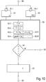
- Fig. 10 shows schematically a method by means of the oscillation states of a wind energy installation WEA as a safety measure (e.g. according to FIG Fig. 1 ) and / or a wind farm (e.g. according to Fig. 2 ) can be recognized comparatively reliably as real oscillations; in particular those that have their cause in the mode of operation of the wind energy installation 100 and / or of the wind park 112 in connection with the electrical supply network 120.
- the aspect of an oscillation detection only for such an oscillation curve which turns out to be a real oscillating oscillation in a wind power plant and / or a wind park coupled to the electrical supply network, has been recognized as particularly relevant by the present concept.
- the mains voltage U (in particular a linked mains voltage, according to the space vector method) is continuously monitored by an oscillation detection unit 930 of Fig. 9 monitored for an oscillating behavior. This is intended to detect when a control algorithm (voltage regulator, reactive power regulator) becomes unstable. This could possibly with reference to the possibilities of FIGS. 5 to 8 occur when control parameters are set too sharply or when network conditions change or when setpoint specifications are changed.
- a control algorithm voltage regulator, reactive power regulator
- the reactive power setpoint of a wind energy installation WEA (setpoint for the WEA, output variable from the wind farm control 131) is constantly monitored for an oscillating behavior. This is intended to detect when a control algorithm (voltage regulator, reactive power regulator) becomes unstable. This could possibly be with reference to the possibilities of FIGS. 5 to 8 occur when control parameters are set too sharply or when network conditions change or when setpoint specifications are changed.
- the oscillation detection can be activated in a starting method step S0; this proves to be particularly useful in a situation as described above.
- this can prevent a parameter set of the wind farm controller 131 that is set too sharply from being throttled or converted into a regular parameter set in the event of activation during the transition to regular operation.
- a time profile of the network voltage U of the electrical supply network 120 is recorded over a first recording period.
- this takes place within the scope of a measurement S1.1 at the network connection point 118 to the electrical supply network 120.
- This detection measure proves to be particularly useful in the event that network stability is rather weak; in that case an oscillation detected over the detection period would already represent a strong indication of an oscillation state.
- step S2 the active power Q of the wind energy installation WEA is recorded as a time profile over a second recording period;
- the first and second recording periods preferably coincide and the active power Q and the mains voltage U are recorded simultaneously.
- the acquisition of a setpoint value for the reactive power Q-SOLL in a step S2.1 at a wind farm control interface 103 to the wind energy installation WEA 100 is advantageous.
- the background to such a measure could be that a determination of an oscillation proves to be significant for an oscillation state especially when the network stability is comparatively strong. Then the oscillating reactive power indicates a regulator oscillation, the oscillation of which should be eliminated.
- the combination of the further steps S1 and S2 includes both weak network stability situations and strong network stability situations.
- the first step S1 is directed to the monitoring of oscillations at the network connection point 118 to the supply network 120
- the second step S2 is directed to the monitoring of oscillations at the wind energy installation WEA itself.
- the combination of the two steps S1, S2 monitors oscillations as they can arise in a coupled wind energy installation 100 or a coupled wind farm 112 to an electrical supply network 120 and which can contribute to undesired oscillatory states.
- Both parameters of a grid voltage U and a reactive power Q-Soll can be measured comparatively easily in steps S1.1 and S2.1 or are already provided as measurement parameters within the scope of normal regulation by means of a wind farm controller 131 for a wind farm 112. They are thus already available in a comparatively simple manner and can be used for the further process.
- a third further step S3 it is determined whether the output power and the mains voltage U have an oscillation curve which is present as an oscillation with a period T and an amplitude A and which can be characterized as an oscillation state over the detection period; i.e. which in particular does not decrease.
- a period T and an amplitude A it is determined whether a period T and an amplitude A can be assigned to the oscillation over the detection period. In other words, it is determined whether it is a relevant oscillation at all and not just a static oscillation that cannot be classified as an oscillation. For this purpose it can be checked, if necessary, whether a determined period T can be assigned to a size frequency with a sufficiently small bandwidth, or it can additionally it can be checked whether the determined period T does not fluctuate more than a predetermined variance in the recording period. It is preferably established that the period T can always be assigned to the same frequency, that is to say is constant over the detection period.
- a period time interval I
- These limit values of the period interval I can result from experience relating to the wind farm control and / or regulating systems 130 and wind farm control properties for a wind energy installation 100 or for a wind farm 112, respectively.
- changing supply network states that occur with other oscillation states are excluded.
- a third test step S3.3 it is determined whether the measured amplitude A is above a threshold value amplitude A s (ie A> A s ). If this is the case, it is checked in a fourth test step S3.4 whether the amplitude values of the amplitude A increase over time over the detection period; ie it is checked whether the gradient degree A is above a limit gradient G s .
- the method described here therefore does not take into account oscillations whose amplitude value of the amplitude A is sufficiently low or whose amplitude value decreases with sufficient speed.
- a third test step S3.3 it can also be checked whether the measured amplitude is above an upper threshold amplitude (A >> A s + ); if this is the case - regardless of whether the amplitude A rises or falls in step S3.4 '- it can be recognized that there is an oscillation state.
- a >> A s + the system reaches its limits and then regardless of whether it is an upswing, downswing or constant oscillation, the control parameter of the wind farm controller 131 can be throttled .
- step S4 for the above-mentioned test steps S3.1, S3.2, S3.3, S3.4 or S3.1, S3.2, S3.3 ', S3.4' all results are positive, that is to say all test queries
- a parameter set of the wind farm control 131 is to be reduced in its values by suitable throttle values ⁇ in a fifth step S5, that is to say usually corresponding setting parameters, ramps or the like.
- the procedure can then again be recorded in step S0 and possibly run in a loop.
- test steps S3.1, S3.2, S3.3, S3.4 or S3.1, S3.2, S3.3 ', S3.4' has to be answered with "NO” is provided in the present case that a parameter change for the controller 500 of the wind farm controller 131 does not take place.
- the basic idea behind this development is that a large part of such vibrations, which do not correspond to all four of the aforementioned test criteria S3.1 to S3.4 / S3.4 ', are either decreasing (that is, they disappear on their own) or are too low (and therefore are irrelevant).
- the test method for detecting an upswing behavior can then be run through as a loop with step S0.
Claims (13)
- Procédé servant à faire fonctionner une éolienne (100) et/ou un parc éolien (112), servant à injecter une puissance électrique dans un réseau d'alimentation (120) électrique, dans lequel une puissance délivrée, en particulier une puissance active et/ou réactive (Q, P), est régulée au moyen d'au moins un module de régulation de puissance (500) d'un dispositif de régulation et/ou de commande (131), présentant les étapes suivantes :- spécification (S0) d'une valeur d'entrée de régulation de puissance et de définition d'une valeur de sortie de régulation de puissance à partir de valeur d'entrée de régulation de puissance ainsi que d'envoi d'une valeur de sortie de régulation de puissance, dans lequel- une évolution dans le temps de la puissance délivrée de la production d'énergie du vent est détectée sur un intervalle de temps de détection (S2), et- une évolution dans le temps de la tension de réseau du réseau d'alimentation électrique est détectée sur un intervalle de temps de détection (S1), dans lequel- il est contrôlé sur l'intervalle de temps de détection si la puissance délivrée et la tension de réseau présentent une évolution oscillatoire, caractérisé en ce que- une oscillation avec une période (T) et avec une amplitude (A) est associée à l'évolution oscillatoire, et- il est constaté que l'oscillation s'arrête sans diminuer ce faisant sur l'intervalle de temps de détection, dans lequel il est constaté que la période (T) a sur l'intervalle de temps de détection une valeur de période à l'intérieur d'une plage de périodes, et/ou- il est constaté que l'amplitude (A) a, sur l'intervalle de temps de détection, une valeur d'amplitude supérieure à une amplitude de valeur de seuil, et/ou- il est constaté que l'amplitude a, sur l'intervalle de temps de détection, une valeur d'amplitude qui augmente, et- un signal est envoyé pour signaler un état d'oscillation ascendante.
- Procédé selon la revendication 1, caractérisé en ce qu'une valeur limite de période inférieure de la plage de périodes est comprise entre 0,05 s et 0,5 s.
- Procédé selon l'une quelconque des revendications précédentes, caractérisé en ce qu'une valeur limite de période supérieure de la plage de périodes est comprise entre 10 s et 30 s.
- Procédé selon l'une quelconque des revendications précédentes, caractérisé en ce qu'il est constaté que- la période a, sur l'intervalle de temps de détection, en particulier au-delà de la valeur de temps limite, une valeur de période largement persistante.
- Procédé selon l'une quelconque des revendications précédentes, caractérisé en ce qu'un intervalle de période d'une puissance réactive et un intervalle de période d'une tension de réseau sont différents et/ou une amplitude de valeur de seuil d'une puissance réactive et une amplitude de valeur de seuil d'une tension de réseau sont différentes, en particulier l'intervalle de période et/ou l'amplitude de valeur de seuil de la puissance réactive sont inférieurs à l'intervalle de période et/ou à l'amplitude de valeur de seuil de la tension de réseau.
- Procédé selon l'une quelconque des revendications précédentes, caractérisé en ce que des états d'oscillation de puissance réactive parasitaires et/ou normaux sont exclus avant que le signal n'affiche l'état d'oscillation ascendante.
- Procédé selon l'une quelconque des revendications précédentes, caractérisé en ce que le signal s'affichant après l'état d'oscillation ascendante, en particulier servant à éliminer un paramètre de régulation réglé de manière trop forte, un paramètre de régulation d'un dispositif de régulation et/ou de commande et/ou d'un dispositif de réseau d'alimentation, sont modifiés, en particulier sont réduits.
- Procédé selon l'une quelconque des revendications précédentes, caractérisé en ce qu'une puissance réactive (Q) de la puissance délivrée, en particulier une valeur théorique de la puissance réactive et/ou une valeur réelle de la puissance réactive (Q), est surveillée.
- Procédé selon l'une quelconque des revendications précédentes, caractérisé en ce que la puissance délivrée et la tension de réseau (U) sont surveillées, en particulier sont mesurées, au-delà de l'intervalle de temps de détection, de préférence il est contrôlé en permanence au-delà de la période détection si la puissance délivrée et la tension de réseau présentent une évolution oscillatoire.
- Dispositif de régulation et/ou de commande servant à faire fonctionner une éolienne et/ou un parc éolien, qui est réalisé pour exécuter un procédé selon l'une quelconque des revendications précédentes, et qui présente :- un module de régulation (500) servant à spécifier une valeur d'entrée de régulation de puissance et servant à définir une valeur de sortie de régulation de puissance à partir de la valeur d'entrée de régulation de puissance ainsi qu'à envoyer la valeur de sortie de régulation de puissance,- un module de mesure d'installation (902) servant à détecter une évolution dans le temps de la puissance délivrée de la génération d'énergie du vent sur un intervalle de temps de détection, et- une unité de mesure de réseau (920) servant à détecter une évolution dans le temps de la tension de réseau du réseau d'alimentation électrique sur un intervalle de temps de détection, et- un module d'évaluation (930), qui est réalisé pour contrôler si la puissance délivrée et la tension de réseau présentent, sur l'intervalle de temps de détection, une évolution oscillatoire, caractérisé en ce que- le module d'évaluation est réalisé en outre pour associer, à l'évolution oscillatoire, une oscillation avec une période (T) et avec une amplitude (A), dans lequel- le module d'évaluation présente par ailleurs une détection d'oscillation ascendante, au moyen de laquelle il peut être constaté que l'oscillation se maintient pendant l'intervalle de temps de détection sans diminuer ce faisant, dans lequel- il est constaté que la période (T) a, sur l'intervalle de temps de détection, une valeur de période à l'intérieur d'une plage de périodes, et/ou- il est constaté que l'amplitude (A) a, sur l'intervalle de temps de détection, une valeur d'amplitude supérieure à une amplitude de valeur de seuil, et/ou- il est constaté que l'amplitude a, sur l'intervalle de temps de détection, une valeur d'amplitude qui augmente, et- un émetteur de signaux servant à envoyer un signal indiquant un état d'oscillation ascendante.
- Dispositif de régulation et/ou de commande selon la revendication 10, caractérisé en ce que le module d'évaluation avec la détection d'oscillation ascendante fait partie d'une commande d'éolienne et/ou d'une commande de parc éolien (130, 131, 132) et/ou le module de mesure d'installation et le module de mesure de réseau sont un dispositif au niveau du point de connexion de réseau (118).
- Eolienne (100) avec un dispositif de régulation et/ou de commande selon la revendication 10 ou 11.
- Parc éolien (120) avec un nombre d'éoliennes et un dispositif de régulation et/ou de commande selon la revendication 10 ou 11.
Applications Claiming Priority (2)
| Application Number | Priority Date | Filing Date | Title |
|---|---|---|---|
| DE102014200740.2A DE102014200740A1 (de) | 2014-01-16 | 2014-01-16 | Verfahren und Regel- und/oder Steuereinrichtung zum Betrieb einer Windenergieanlage und/oder eines Windparks sowie Windenergieanlage und Windpark |
| PCT/EP2015/050143 WO2015106994A1 (fr) | 2014-01-16 | 2015-01-07 | Procédé et dispositif de réglage et/ou commande pour faire fonctionner une éolienne et/ou un parc éolien et éolienne et parc éolien correspondants |
Publications (2)
| Publication Number | Publication Date |
|---|---|
| EP3095165A1 EP3095165A1 (fr) | 2016-11-23 |
| EP3095165B1 true EP3095165B1 (fr) | 2020-10-28 |
Family
ID=52347316
Family Applications (1)
| Application Number | Title | Priority Date | Filing Date |
|---|---|---|---|
| EP15700275.9A Active EP3095165B1 (fr) | 2014-01-16 | 2015-01-07 | Procédé et dispositif de réglage et/ou commande pour faire fonctionner une éolienne et/ou un parc éolien et éolienne et parc éolien correspondants |
Country Status (9)
| Country | Link |
|---|---|
| US (1) | US20160336888A1 (fr) |
| EP (1) | EP3095165B1 (fr) |
| CN (1) | CN105917542B (fr) |
| AR (1) | AR099099A1 (fr) |
| CA (1) | CA2934348C (fr) |
| DE (1) | DE102014200740A1 (fr) |
| DK (1) | DK3095165T3 (fr) |
| TW (1) | TWI555296B (fr) |
| WO (1) | WO2015106994A1 (fr) |
Families Citing this family (24)
| Publication number | Priority date | Publication date | Assignee | Title |
|---|---|---|---|---|
| DE102015201431A1 (de) * | 2015-01-28 | 2016-07-28 | Wobben Properties Gmbh | Verfahren zum Betreiben eines Windparks |
| DE102015120306A1 (de) * | 2015-11-24 | 2017-05-24 | Wobben Properties Gmbh | Verfahren zum Ausgeben von Steuerbefehlen oder Ereignismeldungen für eine Windenergieanlage oder einen Windpark sowie eine Auswerteeinrichtung und ein System hierfür |
| DE102016101468A1 (de) * | 2016-01-27 | 2017-07-27 | Wobben Properties Gmbh | Verfahren zum Einspeisen elektrischer Leistung in ein elektrisches Versorgungsnetz |
| WO2017221430A1 (fr) * | 2016-06-21 | 2017-12-28 | Hitachi, Ltd. | Procédé d'identification permettant d'identifier une résonance d'un réseau électrique, et unité connectée au réseau |
| DE102016009413A1 (de) * | 2016-08-04 | 2018-02-08 | Senvion Gmbh | Verfahren zum Regeln der Blindleistungsabgabe eines Windparks sowie ein entsprechender Windpark |
| EP3318751B1 (fr) * | 2016-11-08 | 2021-07-21 | Siemens Gamesa Renewable Energy A/S | Amortissement des oscillations mécaniques d'une éolienne |
| DE102016124840A1 (de) * | 2016-12-19 | 2018-06-21 | Wobben Properties Gmbh | Verfahren zum Steuern eines Netzwiederaufbaus |
| DK3376026T3 (da) * | 2017-03-13 | 2022-02-28 | Nordex Energy Se & Co Kg | Fremgangsmåde til regulering af aktiv-effekt fra en vindmøllepark, og tilsvarende vindmøllepark |
| EP3407452A1 (fr) * | 2017-05-24 | 2018-11-28 | Siemens Aktiengesellschaft | Commande d'un réseau de distribution |
| CN107238772A (zh) * | 2017-06-28 | 2017-10-10 | 国网辽宁省电力有限公司 | 一种基于功率梯度分量的电压稳定性检测方法 |
| WO2019052614A1 (fr) * | 2017-09-13 | 2019-03-21 | Vestas Wind Systems A/S | Perfectionnements se rapportant à la régulation de tension dans des centrales éoliennes |
| FR3071620B1 (fr) * | 2017-09-26 | 2020-10-02 | Ge Energy Power Conversion Technology Ltd | Dispositif et procede de test de modules de puissance |
| DE102017122695A1 (de) | 2017-09-29 | 2019-04-04 | Wobben Properties Gmbh | Verfahren zum Versorgen von Windenergieanlagenkomponenten mit Energie sowie Energieversorgungseinrichtung und Windenergieanlage damit |
| DE102018102224A1 (de) * | 2018-02-01 | 2019-08-01 | Wobben Properties Gmbh | Verfahren zum Einspeisen elektrischer Leistung in ein elektrisches Versorgungsnetz |
| DE102018002916A1 (de) | 2018-04-10 | 2019-10-10 | Senvion Gmbh | Verfahren, Vorrichtung und Computerprogrammprodukt zum Betrieb einer oder mehrerer Windenergieanlagen |
| DE102018116446A1 (de) * | 2018-07-06 | 2020-01-09 | Wobben Properties Gmbh | Windenergiesystem und Verfahren zum Erkennen niederfrequenter Schwingungen in einem elektrischen Versorgungsnetz |
| DE102018120751A1 (de) * | 2018-08-24 | 2020-02-27 | Wobben Properties Gmbh | Windenergieanlage und Verfahren zum Erkennen niederfrequenter Schwingungen in einem elektrischen Versorgungsnetz |
| US11063441B2 (en) * | 2018-10-18 | 2021-07-13 | General Electric Company | Systems and methods for managing resonance in wind turbine power systems |
| CN110838720B (zh) * | 2019-11-18 | 2021-06-29 | 长沙晟道电气科技有限公司 | 基于多绕组永磁发电机的直流串并联海上风电场及其控制方法 |
| EP3848575A1 (fr) * | 2020-01-09 | 2021-07-14 | Nordex Energy SE & Co. KG | Procédé de fonctionnement d'un parc éolien comprenant plusieurs éoliennes ainsi que parc éolien correspondant |
| CN111900743B (zh) * | 2020-07-28 | 2021-11-16 | 南京东博智慧能源研究院有限公司 | 一种风电调频潜力预测误差分布估计方法 |
| CN113217280A (zh) * | 2021-04-20 | 2021-08-06 | 东方电气风电有限公司 | 一种制动装置及直驱风力发电机的制动式停机控制方法 |
| CN113328434B (zh) * | 2021-05-17 | 2022-05-10 | 浙江运达风电股份有限公司 | 一种满足风电场支撑要求的场级协同控制系统及方法 |
| CN114256868B (zh) * | 2021-11-16 | 2023-01-24 | 中国大唐集团科学技术研究院有限公司火力发电技术研究院 | 风电并网系统宽频带振荡安全域构建方法 |
Family Cites Families (12)
| Publication number | Priority date | Publication date | Assignee | Title |
|---|---|---|---|---|
| PL212009B1 (pl) * | 2001-09-28 | 2012-07-31 | Aloys Wobben | Układ regulacji farmy wiatrowej składającej się z co najmniej dwóch instalacji wiatrowych |
| US7119452B2 (en) * | 2003-09-03 | 2006-10-10 | General Electric Company | Voltage control for wind generators |
| EP1665494B2 (fr) | 2003-09-03 | 2023-06-28 | Siemens Gamesa Renewable Energy Service GmbH | Procédé pour faire fonctionner ou réguler une éolienne et procédé pour mettre à disposition une puissance de régulation primaire au moyen d'éoliennes |
| DE102005032693A1 (de) * | 2005-07-13 | 2007-02-01 | Repower Systems Ag | Leistungsregelung eines Windparks |
| US7639893B2 (en) | 2006-05-17 | 2009-12-29 | Xerox Corporation | Histogram adjustment for high dynamic range image mapping |
| WO2009048964A1 (fr) * | 2007-10-09 | 2009-04-16 | Schweitzer Engineering Laboratories, Inc. | Détection d'oscillation de système d'alimentation en temps réel par l'utilisation d'une analyse modale |
| DE102009031017B4 (de) | 2009-06-29 | 2018-06-21 | Wobben Properties Gmbh | Verfahren und Vorrichtung zur Beobachtung eines dreiphasigen Wechselspannungsnetzes sowie Windenergieanlage |
| WO2012019613A1 (fr) * | 2010-08-13 | 2012-02-16 | Vestas Wind Systems A/S | Production d'électricité à partir de l'énergie éolienne avec fluctuations réduites de puissance |
| EP2594004B1 (fr) * | 2010-09-28 | 2015-03-04 | Siemens Aktiengesellschaft | Amortissement d'oscillation d'énergie électrique par un dispositif de production d'énergie électrique à base de convertisseur |
| DE102011086988B3 (de) * | 2011-11-23 | 2013-03-21 | Suzlon Energy Gmbh | Verfahren zum Betrieb einer Windturbine |
| US9455633B2 (en) * | 2012-01-05 | 2016-09-27 | Ingeteam Power Technology, S.A. | Method and apparatus for controlling a frequency converter |
| EP2662561A1 (fr) * | 2012-05-09 | 2013-11-13 | Siemens Aktiengesellschaft | Procédé et dispositif d'amortissement d'oscillation d'arbre |
-
2014
- 2014-01-16 DE DE102014200740.2A patent/DE102014200740A1/de not_active Withdrawn
- 2014-12-29 TW TW103146131A patent/TWI555296B/zh not_active IP Right Cessation
-
2015
- 2015-01-07 DK DK15700275.9T patent/DK3095165T3/da active
- 2015-01-07 CN CN201580004818.3A patent/CN105917542B/zh active Active
- 2015-01-07 EP EP15700275.9A patent/EP3095165B1/fr active Active
- 2015-01-07 US US15/112,128 patent/US20160336888A1/en not_active Abandoned
- 2015-01-07 CA CA2934348A patent/CA2934348C/fr active Active
- 2015-01-07 WO PCT/EP2015/050143 patent/WO2015106994A1/fr active Application Filing
- 2015-01-15 AR ARP150100100A patent/AR099099A1/es unknown
Also Published As
| Publication number | Publication date |
|---|---|
| DE102014200740A1 (de) | 2015-07-16 |
| CN105917542A (zh) | 2016-08-31 |
| CA2934348C (fr) | 2020-08-04 |
| CN105917542B (zh) | 2020-03-31 |
| CA2934348A1 (fr) | 2015-07-23 |
| EP3095165A1 (fr) | 2016-11-23 |
| DK3095165T3 (da) | 2020-11-30 |
| US20160336888A1 (en) | 2016-11-17 |
| TWI555296B (zh) | 2016-10-21 |
| TW201541796A (zh) | 2015-11-01 |
| WO2015106994A1 (fr) | 2015-07-23 |
| AR099099A1 (es) | 2016-06-29 |
Similar Documents
| Publication | Publication Date | Title |
|---|---|---|
| EP3095165B1 (fr) | Procédé et dispositif de réglage et/ou commande pour faire fonctionner une éolienne et/ou un parc éolien et éolienne et parc éolien correspondants | |
| EP2872777B1 (fr) | Procédé pour commander un générateur électrique | |
| EP2875562B1 (fr) | Procédé de commande d'un parc éolien | |
| EP3408913B1 (fr) | Procédé d'injection d'énergie électrique dans un réseau d'alimentation électrique | |
| EP2556247B1 (fr) | Régulation d'inertie dynamique | |
| EP2873129B1 (fr) | Procédé et dispositif pour injecter de l'énergie électrique dans un réseau d'alimentation électrique | |
| EP3095168B1 (fr) | Méthode de reglage et/ou controle pour l'exploitation d'une centrale éolienne et/ou d'un parc d'éoliennes et centrale éolienne et parc d'éoliennes | |
| EP2989321B1 (fr) | Procédé de réglage d'un parc éolien | |
| EP3008334B1 (fr) | Procédé pour injecter une puissance électrique dans un réseau de distribution électrique | |
| WO2018228901A1 (fr) | Éolienne ou parc éolien servant à injecter une puissance électrique | |
| EP3420222B1 (fr) | Procédé et module de régulation de parc éolien pour la régulation d'un parc éolien | |
| EP3548737A1 (fr) | Éolienne et procédé permettant de faire fonctionner une éolienne | |
| EP3818609A1 (fr) | Procédé pour commander un parc éolien | |
| EP3818384A1 (fr) | Système éolien et procédé pour détecter des oscillations de basse fréquence dans un réseau d'alimentation électrique | |
| DE102013204600A1 (de) | Windkraftanlage mit Frequenzmessung | |
| DE102013106151B4 (de) | Kaskadierung und Energiespeicher | |
| DE102018108023A1 (de) | Verfahren zum Einspeisen elektrischer Leistung in ein elektrisches Versorgungsnetz | |
| EP3577738A1 (fr) | Procédé d'injection de puissance électrique dans un réseau de distribution électrique | |
| EP3891384A1 (fr) | Procédé servant à faire fonctionner au moins une éolienne, ainsi que dispositif associé | |
| EP3514910A1 (fr) | Procédé de fonctionnement d'une éolienne | |
| WO2020008033A1 (fr) | Procédé pour injecter une puissance électrique dans un réseau d'alimentation électrique | |
| EP3511564A1 (fr) | Procédé et système de commande d'une éolienne | |
| EP3993215A1 (fr) | Bandes frt dynamiques pour éoliennes | |
| EP3852214A1 (fr) | Procédé de commande d'une éolienne | |
| EP3813218A1 (fr) | Procédé d'injection de l'énergie électrique dans un réseau d'alimentation électrique |
Legal Events
| Date | Code | Title | Description |
|---|---|---|---|
| PUAI | Public reference made under article 153(3) epc to a published international application that has entered the european phase |
Free format text: ORIGINAL CODE: 0009012 |
|
| 17P | Request for examination filed |
Effective date: 20160816 |
|
| AK | Designated contracting states |
Kind code of ref document: A1 Designated state(s): AL AT BE BG CH CY CZ DE DK EE ES FI FR GB GR HR HU IE IS IT LI LT LU LV MC MK MT NL NO PL PT RO RS SE SI SK SM TR |
|
| AX | Request for extension of the european patent |
Extension state: BA ME |
|
| DAX | Request for extension of the european patent (deleted) | ||
| GRAP | Despatch of communication of intention to grant a patent |
Free format text: ORIGINAL CODE: EPIDOSNIGR1 |
|
| STAA | Information on the status of an ep patent application or granted ep patent |
Free format text: STATUS: GRANT OF PATENT IS INTENDED |
|
| INTG | Intention to grant announced |
Effective date: 20200602 |
|
| GRAS | Grant fee paid |
Free format text: ORIGINAL CODE: EPIDOSNIGR3 |
|
| GRAA | (expected) grant |
Free format text: ORIGINAL CODE: 0009210 |
|
| STAA | Information on the status of an ep patent application or granted ep patent |
Free format text: STATUS: THE PATENT HAS BEEN GRANTED |
|
| AK | Designated contracting states |
Kind code of ref document: B1 Designated state(s): AL AT BE BG CH CY CZ DE DK EE ES FI FR GB GR HR HU IE IS IT LI LT LU LV MC MK MT NL NO PL PT RO RS SE SI SK SM TR |
|
| REG | Reference to a national code |
Ref country code: GB Ref legal event code: FG4D Free format text: NOT ENGLISH |
|
| REG | Reference to a national code |
Ref country code: CH Ref legal event code: EP |
|
| REG | Reference to a national code |
Ref country code: DE Ref legal event code: R096 Ref document number: 502015013702 Country of ref document: DE |
|
| REG | Reference to a national code |
Ref country code: AT Ref legal event code: REF Ref document number: 1329196 Country of ref document: AT Kind code of ref document: T Effective date: 20201115 |
|
| REG | Reference to a national code |
Ref country code: IE Ref legal event code: FG4D Free format text: LANGUAGE OF EP DOCUMENT: GERMAN |
|
| REG | Reference to a national code |
Ref country code: DK Ref legal event code: T3 Effective date: 20201124 |
|
| REG | Reference to a national code |
Ref country code: NL Ref legal event code: FP |
|
| PG25 | Lapsed in a contracting state [announced via postgrant information from national office to epo] |
Ref country code: RS Free format text: LAPSE BECAUSE OF FAILURE TO SUBMIT A TRANSLATION OF THE DESCRIPTION OR TO PAY THE FEE WITHIN THE PRESCRIBED TIME-LIMIT Effective date: 20201028 Ref country code: FI Free format text: LAPSE BECAUSE OF FAILURE TO SUBMIT A TRANSLATION OF THE DESCRIPTION OR TO PAY THE FEE WITHIN THE PRESCRIBED TIME-LIMIT Effective date: 20201028 Ref country code: NO Free format text: LAPSE BECAUSE OF FAILURE TO SUBMIT A TRANSLATION OF THE DESCRIPTION OR TO PAY THE FEE WITHIN THE PRESCRIBED TIME-LIMIT Effective date: 20210128 Ref country code: PT Free format text: LAPSE BECAUSE OF FAILURE TO SUBMIT A TRANSLATION OF THE DESCRIPTION OR TO PAY THE FEE WITHIN THE PRESCRIBED TIME-LIMIT Effective date: 20210301 Ref country code: GR Free format text: LAPSE BECAUSE OF FAILURE TO SUBMIT A TRANSLATION OF THE DESCRIPTION OR TO PAY THE FEE WITHIN THE PRESCRIBED TIME-LIMIT Effective date: 20210129 |
|
| REG | Reference to a national code |
Ref country code: LT Ref legal event code: MG4D |
|
| PG25 | Lapsed in a contracting state [announced via postgrant information from national office to epo] |
Ref country code: IS Free format text: LAPSE BECAUSE OF FAILURE TO SUBMIT A TRANSLATION OF THE DESCRIPTION OR TO PAY THE FEE WITHIN THE PRESCRIBED TIME-LIMIT Effective date: 20210228 Ref country code: LV Free format text: LAPSE BECAUSE OF FAILURE TO SUBMIT A TRANSLATION OF THE DESCRIPTION OR TO PAY THE FEE WITHIN THE PRESCRIBED TIME-LIMIT Effective date: 20201028 Ref country code: SE Free format text: LAPSE BECAUSE OF FAILURE TO SUBMIT A TRANSLATION OF THE DESCRIPTION OR TO PAY THE FEE WITHIN THE PRESCRIBED TIME-LIMIT Effective date: 20201028 Ref country code: PL Free format text: LAPSE BECAUSE OF FAILURE TO SUBMIT A TRANSLATION OF THE DESCRIPTION OR TO PAY THE FEE WITHIN THE PRESCRIBED TIME-LIMIT Effective date: 20201028 Ref country code: ES Free format text: LAPSE BECAUSE OF FAILURE TO SUBMIT A TRANSLATION OF THE DESCRIPTION OR TO PAY THE FEE WITHIN THE PRESCRIBED TIME-LIMIT Effective date: 20201028 Ref country code: BG Free format text: LAPSE BECAUSE OF FAILURE TO SUBMIT A TRANSLATION OF THE DESCRIPTION OR TO PAY THE FEE WITHIN THE PRESCRIBED TIME-LIMIT Effective date: 20210128 |
|
| PG25 | Lapsed in a contracting state [announced via postgrant information from national office to epo] |
Ref country code: HR Free format text: LAPSE BECAUSE OF FAILURE TO SUBMIT A TRANSLATION OF THE DESCRIPTION OR TO PAY THE FEE WITHIN THE PRESCRIBED TIME-LIMIT Effective date: 20201028 |
|
| REG | Reference to a national code |
Ref country code: DE Ref legal event code: R097 Ref document number: 502015013702 Country of ref document: DE |
|
| PG25 | Lapsed in a contracting state [announced via postgrant information from national office to epo] |
Ref country code: RO Free format text: LAPSE BECAUSE OF FAILURE TO SUBMIT A TRANSLATION OF THE DESCRIPTION OR TO PAY THE FEE WITHIN THE PRESCRIBED TIME-LIMIT Effective date: 20201028 Ref country code: SK Free format text: LAPSE BECAUSE OF FAILURE TO SUBMIT A TRANSLATION OF THE DESCRIPTION OR TO PAY THE FEE WITHIN THE PRESCRIBED TIME-LIMIT Effective date: 20201028 Ref country code: LT Free format text: LAPSE BECAUSE OF FAILURE TO SUBMIT A TRANSLATION OF THE DESCRIPTION OR TO PAY THE FEE WITHIN THE PRESCRIBED TIME-LIMIT Effective date: 20201028 Ref country code: SM Free format text: LAPSE BECAUSE OF FAILURE TO SUBMIT A TRANSLATION OF THE DESCRIPTION OR TO PAY THE FEE WITHIN THE PRESCRIBED TIME-LIMIT Effective date: 20201028 Ref country code: CZ Free format text: LAPSE BECAUSE OF FAILURE TO SUBMIT A TRANSLATION OF THE DESCRIPTION OR TO PAY THE FEE WITHIN THE PRESCRIBED TIME-LIMIT Effective date: 20201028 Ref country code: EE Free format text: LAPSE BECAUSE OF FAILURE TO SUBMIT A TRANSLATION OF THE DESCRIPTION OR TO PAY THE FEE WITHIN THE PRESCRIBED TIME-LIMIT Effective date: 20201028 |
|
| PG25 | Lapsed in a contracting state [announced via postgrant information from national office to epo] |
Ref country code: MC Free format text: LAPSE BECAUSE OF FAILURE TO SUBMIT A TRANSLATION OF THE DESCRIPTION OR TO PAY THE FEE WITHIN THE PRESCRIBED TIME-LIMIT Effective date: 20201028 |
|
| REG | Reference to a national code |
Ref country code: CH Ref legal event code: PL |
|
| PLBE | No opposition filed within time limit |
Free format text: ORIGINAL CODE: 0009261 |
|
| STAA | Information on the status of an ep patent application or granted ep patent |
Free format text: STATUS: NO OPPOSITION FILED WITHIN TIME LIMIT |
|
| PG25 | Lapsed in a contracting state [announced via postgrant information from national office to epo] |
Ref country code: LU Free format text: LAPSE BECAUSE OF NON-PAYMENT OF DUE FEES Effective date: 20210107 |
|
| 26N | No opposition filed |
Effective date: 20210729 |
|
| REG | Reference to a national code |
Ref country code: BE Ref legal event code: MM Effective date: 20210131 |
|
| PG25 | Lapsed in a contracting state [announced via postgrant information from national office to epo] |
Ref country code: AL Free format text: LAPSE BECAUSE OF FAILURE TO SUBMIT A TRANSLATION OF THE DESCRIPTION OR TO PAY THE FEE WITHIN THE PRESCRIBED TIME-LIMIT Effective date: 20201028 Ref country code: IT Free format text: LAPSE BECAUSE OF FAILURE TO SUBMIT A TRANSLATION OF THE DESCRIPTION OR TO PAY THE FEE WITHIN THE PRESCRIBED TIME-LIMIT Effective date: 20201028 |
|
| PG25 | Lapsed in a contracting state [announced via postgrant information from national office to epo] |
Ref country code: LI Free format text: LAPSE BECAUSE OF NON-PAYMENT OF DUE FEES Effective date: 20210131 Ref country code: CH Free format text: LAPSE BECAUSE OF NON-PAYMENT OF DUE FEES Effective date: 20210131 Ref country code: SI Free format text: LAPSE BECAUSE OF FAILURE TO SUBMIT A TRANSLATION OF THE DESCRIPTION OR TO PAY THE FEE WITHIN THE PRESCRIBED TIME-LIMIT Effective date: 20201028 |
|
| PG25 | Lapsed in a contracting state [announced via postgrant information from national office to epo] |
Ref country code: IE Free format text: LAPSE BECAUSE OF NON-PAYMENT OF DUE FEES Effective date: 20210107 |
|
| REG | Reference to a national code |
Ref country code: AT Ref legal event code: MM01 Ref document number: 1329196 Country of ref document: AT Kind code of ref document: T Effective date: 20210107 |
|
| PG25 | Lapsed in a contracting state [announced via postgrant information from national office to epo] |
Ref country code: AT Free format text: LAPSE BECAUSE OF NON-PAYMENT OF DUE FEES Effective date: 20210107 |
|
| PG25 | Lapsed in a contracting state [announced via postgrant information from national office to epo] |
Ref country code: IS Free format text: LAPSE BECAUSE OF FAILURE TO SUBMIT A TRANSLATION OF THE DESCRIPTION OR TO PAY THE FEE WITHIN THE PRESCRIBED TIME-LIMIT Effective date: 20210228 |
|
| PG25 | Lapsed in a contracting state [announced via postgrant information from national office to epo] |
Ref country code: BE Free format text: LAPSE BECAUSE OF NON-PAYMENT OF DUE FEES Effective date: 20210131 |
|
| PGFP | Annual fee paid to national office [announced via postgrant information from national office to epo] |
Ref country code: FR Payment date: 20230123 Year of fee payment: 9 Ref country code: DK Payment date: 20230123 Year of fee payment: 9 |
|
| PG25 | Lapsed in a contracting state [announced via postgrant information from national office to epo] |
Ref country code: HU Free format text: LAPSE BECAUSE OF FAILURE TO SUBMIT A TRANSLATION OF THE DESCRIPTION OR TO PAY THE FEE WITHIN THE PRESCRIBED TIME-LIMIT; INVALID AB INITIO Effective date: 20150107 |
|
| PGFP | Annual fee paid to national office [announced via postgrant information from national office to epo] |
Ref country code: GB Payment date: 20230124 Year of fee payment: 9 Ref country code: DE Payment date: 20220629 Year of fee payment: 9 |
|
| PG25 | Lapsed in a contracting state [announced via postgrant information from national office to epo] |
Ref country code: CY Free format text: LAPSE BECAUSE OF FAILURE TO SUBMIT A TRANSLATION OF THE DESCRIPTION OR TO PAY THE FEE WITHIN THE PRESCRIBED TIME-LIMIT Effective date: 20201028 |
|
| PGFP | Annual fee paid to national office [announced via postgrant information from national office to epo] |
Ref country code: NL Payment date: 20230124 Year of fee payment: 9 |
|
| PGFP | Annual fee paid to national office [announced via postgrant information from national office to epo] |
Ref country code: NL Payment date: 20240123 Year of fee payment: 10 |