EP4170766A1 - Secondary battery and manufacturing method for same - Google Patents
Secondary battery and manufacturing method for same Download PDFInfo
- Publication number
- EP4170766A1 EP4170766A1 EP21894853.7A EP21894853A EP4170766A1 EP 4170766 A1 EP4170766 A1 EP 4170766A1 EP 21894853 A EP21894853 A EP 21894853A EP 4170766 A1 EP4170766 A1 EP 4170766A1
- Authority
- EP
- European Patent Office
- Prior art keywords
- electrode
- separator
- adhesive
- manufacturing
- secondary battery
- Prior art date
- Legal status (The legal status is an assumption and is not a legal conclusion. Google has not performed a legal analysis and makes no representation as to the accuracy of the status listed.)
- Pending
Links
- 238000004519 manufacturing process Methods 0.000 title claims abstract description 168
- 239000000853 adhesive Substances 0.000 claims abstract description 221
- 230000001070 adhesive effect Effects 0.000 claims abstract description 221
- 238000000034 method Methods 0.000 claims abstract description 137
- 239000008151 electrolyte solution Substances 0.000 claims abstract description 43
- 238000007789 sealing Methods 0.000 claims abstract description 8
- 239000012790 adhesive layer Substances 0.000 claims description 52
- 230000015572 biosynthetic process Effects 0.000 claims description 26
- NIXOWILDQLNWCW-UHFFFAOYSA-M Acrylate Chemical compound [O-]C(=O)C=C NIXOWILDQLNWCW-UHFFFAOYSA-M 0.000 claims description 7
- 239000003960 organic solvent Substances 0.000 claims description 6
- 239000007789 gas Substances 0.000 description 16
- 238000012546 transfer Methods 0.000 description 10
- 230000032683 aging Effects 0.000 description 9
- 238000003825 pressing Methods 0.000 description 8
- 238000007872 degassing Methods 0.000 description 7
- 239000010410 layer Substances 0.000 description 7
- 238000003475 lamination Methods 0.000 description 6
- 230000000712 assembly Effects 0.000 description 4
- 238000000429 assembly Methods 0.000 description 4
- 238000004090 dissolution Methods 0.000 description 4
- 238000010030 laminating Methods 0.000 description 4
- HBBGRARXTFLTSG-UHFFFAOYSA-N Lithium ion Chemical compound [Li+] HBBGRARXTFLTSG-UHFFFAOYSA-N 0.000 description 3
- 230000008901 benefit Effects 0.000 description 3
- 230000002950 deficient Effects 0.000 description 3
- 230000006866 deterioration Effects 0.000 description 3
- 238000007599 discharging Methods 0.000 description 3
- 229910001416 lithium ion Inorganic materials 0.000 description 3
- 239000000047 product Substances 0.000 description 3
- CSCPPACGZOOCGX-UHFFFAOYSA-N Acetone Chemical compound CC(C)=O CSCPPACGZOOCGX-UHFFFAOYSA-N 0.000 description 2
- KMTRUDSVKNLOMY-UHFFFAOYSA-N Ethylene carbonate Chemical compound O=C1OCCO1 KMTRUDSVKNLOMY-UHFFFAOYSA-N 0.000 description 2
- 238000006243 chemical reaction Methods 0.000 description 2
- 238000012790 confirmation Methods 0.000 description 2
- 238000005520 cutting process Methods 0.000 description 2
- 230000000694 effects Effects 0.000 description 2
- JBTWLSYIZRCDFO-UHFFFAOYSA-N ethyl methyl carbonate Chemical compound CCOC(=O)OC JBTWLSYIZRCDFO-UHFFFAOYSA-N 0.000 description 2
- 238000003860 storage Methods 0.000 description 2
- 238000001994 activation Methods 0.000 description 1
- 238000004458 analytical method Methods 0.000 description 1
- OJIJEKBXJYRIBZ-UHFFFAOYSA-N cadmium nickel Chemical compound [Ni].[Cd] OJIJEKBXJYRIBZ-UHFFFAOYSA-N 0.000 description 1
- 239000000919 ceramic Substances 0.000 description 1
- 230000000593 degrading effect Effects 0.000 description 1
- 230000002542 deteriorative effect Effects 0.000 description 1
- 239000007772 electrode material Substances 0.000 description 1
- 238000003411 electrode reaction Methods 0.000 description 1
- 239000003792 electrolyte Substances 0.000 description 1
- 238000005516 engineering process Methods 0.000 description 1
- 239000012467 final product Substances 0.000 description 1
- 239000001257 hydrogen Substances 0.000 description 1
- 229910052739 hydrogen Inorganic materials 0.000 description 1
- 230000002452 interceptive effect Effects 0.000 description 1
- 239000000463 material Substances 0.000 description 1
- 238000012986 modification Methods 0.000 description 1
- 230000004048 modification Effects 0.000 description 1
- 229920001690 polydopamine Polymers 0.000 description 1
- 229920000642 polymer Polymers 0.000 description 1
- 238000012805 post-processing Methods 0.000 description 1
- 239000002002 slurry Substances 0.000 description 1
- 239000000243 solution Substances 0.000 description 1
- 230000009897 systematic effect Effects 0.000 description 1
Images


Classifications
-
- H—ELECTRICITY
- H01—ELECTRIC ELEMENTS
- H01M—PROCESSES OR MEANS, e.g. BATTERIES, FOR THE DIRECT CONVERSION OF CHEMICAL ENERGY INTO ELECTRICAL ENERGY
- H01M50/00—Constructional details or processes of manufacture of the non-active parts of electrochemical cells other than fuel cells, e.g. hybrid cells
- H01M50/10—Primary casings, jackets or wrappings of a single cell or a single battery
- H01M50/102—Primary casings, jackets or wrappings of a single cell or a single battery characterised by their shape or physical structure
- H01M50/105—Pouches or flexible bags
-
- H—ELECTRICITY
- H01—ELECTRIC ELEMENTS
- H01M—PROCESSES OR MEANS, e.g. BATTERIES, FOR THE DIRECT CONVERSION OF CHEMICAL ENERGY INTO ELECTRICAL ENERGY
- H01M10/00—Secondary cells; Manufacture thereof
- H01M10/04—Construction or manufacture in general
- H01M10/0459—Cells or batteries with folded separator between plate-like electrodes
-
- H—ELECTRICITY
- H01—ELECTRIC ELEMENTS
- H01M—PROCESSES OR MEANS, e.g. BATTERIES, FOR THE DIRECT CONVERSION OF CHEMICAL ENERGY INTO ELECTRICAL ENERGY
- H01M10/00—Secondary cells; Manufacture thereof
- H01M10/04—Construction or manufacture in general
- H01M10/049—Processes for forming or storing electrodes in the battery container
-
- H—ELECTRICITY
- H01—ELECTRIC ELEMENTS
- H01M—PROCESSES OR MEANS, e.g. BATTERIES, FOR THE DIRECT CONVERSION OF CHEMICAL ENERGY INTO ELECTRICAL ENERGY
- H01M10/00—Secondary cells; Manufacture thereof
- H01M10/05—Accumulators with non-aqueous electrolyte
- H01M10/058—Construction or manufacture
- H01M10/0585—Construction or manufacture of accumulators having only flat construction elements, i.e. flat positive electrodes, flat negative electrodes and flat separators
-
- H—ELECTRICITY
- H01—ELECTRIC ELEMENTS
- H01M—PROCESSES OR MEANS, e.g. BATTERIES, FOR THE DIRECT CONVERSION OF CHEMICAL ENERGY INTO ELECTRICAL ENERGY
- H01M50/00—Constructional details or processes of manufacture of the non-active parts of electrochemical cells other than fuel cells, e.g. hybrid cells
- H01M50/40—Separators; Membranes; Diaphragms; Spacing elements inside cells
- H01M50/46—Separators, membranes or diaphragms characterised by their combination with electrodes
- H01M50/461—Separators, membranes or diaphragms characterised by their combination with electrodes with adhesive layers between electrodes and separators
-
- H—ELECTRICITY
- H01—ELECTRIC ELEMENTS
- H01M—PROCESSES OR MEANS, e.g. BATTERIES, FOR THE DIRECT CONVERSION OF CHEMICAL ENERGY INTO ELECTRICAL ENERGY
- H01M50/00—Constructional details or processes of manufacture of the non-active parts of electrochemical cells other than fuel cells, e.g. hybrid cells
- H01M50/40—Separators; Membranes; Diaphragms; Spacing elements inside cells
- H01M50/463—Separators, membranes or diaphragms characterised by their shape
- H01M50/466—U-shaped, bag-shaped or folded
-
- H—ELECTRICITY
- H01—ELECTRIC ELEMENTS
- H01M—PROCESSES OR MEANS, e.g. BATTERIES, FOR THE DIRECT CONVERSION OF CHEMICAL ENERGY INTO ELECTRICAL ENERGY
- H01M50/00—Constructional details or processes of manufacture of the non-active parts of electrochemical cells other than fuel cells, e.g. hybrid cells
- H01M50/50—Current conducting connections for cells or batteries
- H01M50/531—Electrode connections inside a battery casing
- H01M50/536—Electrode connections inside a battery casing characterised by the method of fixing the leads to the electrodes, e.g. by welding
-
- Y—GENERAL TAGGING OF NEW TECHNOLOGICAL DEVELOPMENTS; GENERAL TAGGING OF CROSS-SECTIONAL TECHNOLOGIES SPANNING OVER SEVERAL SECTIONS OF THE IPC; TECHNICAL SUBJECTS COVERED BY FORMER USPC CROSS-REFERENCE ART COLLECTIONS [XRACs] AND DIGESTS
- Y02—TECHNOLOGIES OR APPLICATIONS FOR MITIGATION OR ADAPTATION AGAINST CLIMATE CHANGE
- Y02E—REDUCTION OF GREENHOUSE GAS [GHG] EMISSIONS, RELATED TO ENERGY GENERATION, TRANSMISSION OR DISTRIBUTION
- Y02E60/00—Enabling technologies; Technologies with a potential or indirect contribution to GHG emissions mitigation
- Y02E60/10—Energy storage using batteries
-
- Y—GENERAL TAGGING OF NEW TECHNOLOGICAL DEVELOPMENTS; GENERAL TAGGING OF CROSS-SECTIONAL TECHNOLOGIES SPANNING OVER SEVERAL SECTIONS OF THE IPC; TECHNICAL SUBJECTS COVERED BY FORMER USPC CROSS-REFERENCE ART COLLECTIONS [XRACs] AND DIGESTS
- Y02—TECHNOLOGIES OR APPLICATIONS FOR MITIGATION OR ADAPTATION AGAINST CLIMATE CHANGE
- Y02P—CLIMATE CHANGE MITIGATION TECHNOLOGIES IN THE PRODUCTION OR PROCESSING OF GOODS
- Y02P70/00—Climate change mitigation technologies in the production process for final industrial or consumer products
- Y02P70/50—Manufacturing or production processes characterised by the final manufactured product
Definitions
- the present invention relates to a secondary battery and a method for manufacturing the same, which is a method for preventing an electrode or a separator from being separated from a fixed position when manufacturing a unit cell by stacking the electrode and the separator, and more particularly, to a secondary battery and a method for manufacturing the same, which is capable of reducing production costs, reducing a defective rate in a process, which is caused by high-temperature heat and a high pressure, and preventing performance of the battery from being deteriorated, when compared to a method for manufacturing a radical unit cell through a lamination according to the related art.
- secondary batteries include nickel-cadmium batteries, nickel-hydrogen batteries, lithium ion batteries, and lithium ion polymer batteries.
- Such a secondary battery is being applied to and used in small-sized products such as digital cameras, P-DVDs, MP3Ps, mobile phones, PDAs, portable game devices, power tools, E-bikes, and the like as well as large-sized products requiring high power such as electric vehicles and hybrid vehicles, power storage devices for storing surplus power or renewable energy, and backup power storage devices.
- electrode active material slurry is applied to a positive electrode collector and a negative electrode collector to manufacture a positive electrode and a negative electrode, and then, the electrodes are laminated on both sides of a separator, thereby forming an electrode assembly having a predetermined shape. Further, the electrode assembly is accommodated in a battery case, an electrolyte solution is injected therein and then the battery case is sealed.
- the electrode assembly is classified into various types.
- the electrode assembly is classified into a simple stack type, in which a positive electrode, a separator, and a negative electrode are simply and continuously stacked to cross each other without manufacturing a unit cell, a lamination & stack (L&S) type, in which unit cells are manufactured using positive electrodes, separators, and negative electrodes and then are stacked, a stack & folding (S&F) type, in which a plurality of electrodes or unit cells are attached to be separated from each other on one surface of a separator sheet, of which one side is long, and then the separator sheet is repeatedly folded from one end thereof in the same direction, and a Z-folding type, in which a plurality of electrodes or unit cells are alternately attached on one surface and the other surface of a separator sheet, of which one side is long, and then a process, in which the separator sheet is folded from one end thereof in a specific direction and then folded in an opposite direction, is alternately and repeatedly performed.
- L&S la
- the unit cell in order to manufacture the lamination & stack type electrode assembly, the stack & fold type electrode assembly, or the Z-folding type electrode assembly, the unit cell may be manufactured first.
- the separator in order to manufacture the unit cell, the separator may be stacked on each of top and bottom surfaces of a center electrode, and then an upper electrode may be further stacked at the uppermost end.
- a laminating process in which heat and a pressure are applied to the stack, in which the electrode and the separator are stacked, may be performed. Since the lamination process is performed, the electrode and the separator may be bonded to each other to firmly form the unit cell.
- the electrode and the separator are not bonded to each other until the lamination process is performed on the stack, in which the electrode and the separator are stacked, but are only in contact with each other. Therefore, in order to perform the laminating process, there is a problem that the electrode is separated from a fixed position in the process of transferring the stack. In addition, since the laminating process applies high-temperature heat and a high pressure to the stack, the electrode may be damaged. Furthermore, recently, a separator capable of adhering to an electrode even with low-temperature heat and a low pressure has been developed, but the separator consumes an excessively high manufacturing cost, which is not economical and also deteriorates process efficiency.
- the present invention has been devised to solve the above problems, and an object of the present invention is to provide a secondary battery and a method for manufacturing the same, which is capable of preventing an electrode or a separator from being separated from a fixed position when manufacturing a unit cell by stacking the electrode and the separator.
- an object of the present invention is to provide a secondary battery and a method for manufacturing the same, which is capable of reducing production costs, reducing a defective rate in a process, which is caused by high-temperature heat and a high pressure, and preventing performance of the battery from being deteriorated, when compared to a method for manufacturing a radical unit cell through a lamination according to the related art.
- a method for manufacturing a secondary battery according to the present invention comprises manufacturing an electrode assembly by alternately stacking an electrode and a separator and applying an adhesive to at least one surface of the electrode and the separator to adhere the electrode and the separator to each other; and manufacturing a battery cell by accommodating the electrode assembly together with an electrolyte solution in a pouch case and sealing the pouch case, wherein at least portion of the adhesive is dissolved in the electrolyte solution, and thereby a mark, which the adhesive was applied to, is formed on the separator.
- the step of manufacturing the battery cell may further comprise a formation process of charging the battery cell at a temperature that is higher than a room temperature to activate the battery cell, wherein the at least portion of the adhesive may be dissolved in the electrolyte solution in the formation process.
- the formation process may be performed at a temperature of 50 degrees Celsius or more and 70 degrees Celsius or less.
- the formation process may further comprise a process of compressing both side surfaces of the initial cell by using a jig.
- the formation process may be performed at a temperature of 55 degrees Celsius or more and 65 degrees Celsius or less, and the adhesive may be completely dissolved in the electrolyte solution in the formation process so that the adhesive is removed from a surface of the electrode.
- the adhesive may be an acrylate-based adhesive, and the electrolyte solution may be an organic solvent.
- the secondary battery manufacturing method may further comprise manufacturing a radical unit, wherein the radical unit may be a unit which the electrode and the separator are stacked, wherein the electrode assembly may be manufactured by attaching a fixing tape around an electrode stack, in which a plurality of radical units are stacked.
- the step of manufacturing the radical unit may comprise: unwinding a lower separator from a lower separator reel; applying the adhesive to at least portion of one surface of the unwound lower separator, which faces an upper side, through a first nozzle; positioning a first electrode on one surface of the lower separator to which the adhesive is applied; unwinding an upper separator from an upper separator reel; applying the adhesive to at least portion of one surface of the unwound upper separator, which is in contact with the first electrode, through a second nozzle; applying the adhesive to at least portion of the other surface of the upper separator, which faces the upper side, through a third nozzle; and positioning a second electrode on the other surface of the upper separator, to which the adhesive is applied, after applying the adhesive through the third nozzle.
- the first nozzle, the second nozzle, and the third nozzle may apply the adhesive in a form a plurality of dots.
- the secondary battery manufacturing method may further comprise manufacturing a radical unit, wherein the radical unit is a unit which the electrode and the separator are stacked, the separator being folded to cover the electrode, wherein the electrode assembly is manufactured by repeatedly forming the radical unit.
- the step of manufacturing the radical unit may comprise: unwinding an electrode sheet from an electrode reel to form a plurality of electrodes from the electrode sheet; unwinding the separator to be stacked with the electrode, from a separator reel; positioning the separator on an upper surface of a table; and applying the adhesive to at least portion of the separator which is positioned on the table and the electrode, through a nozzle, wherein the electrode comprises a first electrode and a second electrode.
- the method may further comprise a folding step after the step of applying the adhesive, wherein in the folding step, when the first electrode is positioned on the separator, one side of the separator may be folded to cover the first electrode, and when the second electrode is positioned on the separator, the other side of the separator may be folded to cover the second electrode.
- the nozzle may apply the adhesive in a form a plurality of dots.
- a secondary battery according to the present invention may comprise an electrode assembly in which an electrode and a separator are alternately stacked; and a pouch case for accommodating the electrode assembly together with the electrolyte solution, wherein a mark, which at least one adhesive was applied to, remains on a surface of the separator, which is in contact with the electrode, and the mark, which the adhesive was applied to, is a mark in which the first adhesive layer having been formed between the electrode and the separator was dissolved into the electrolyte solution.
- the first adhesive layer may be formed by applying the adhesive in a form of a plurality of dots, and the mark, which the adhesive was applied to, is formed in the form of dots at a position where the first adhesive layer is formed.
- the adhesive may be an acrylate-based adhesive, and the electrolyte solution may be an organic solvent.
- the electrode may comprise a first electrode and a second electrode
- the separator may comprise an upper separator and a lower separator
- the electrode assembly may have a structure in which the lower separator, the first electrode, the upper separator, and the second electrode are alternately stacked.
- the electrode may comprise a first electrode and a second electrode, and the electrode assembly may be configured such that: the first electrode is positioned on the separator, and one side of the separator is folded to cover the first electrode, and the second electrode is positioned on the separator, and the other side of the separator is folded to cover the second electrode.
- An electrode tab may be formed at one end of the electrode, a second adhesive layer may be formed between the electrode tab and the separator, and the second adhesive layer may comprise an adhesive component that is not dissolved into the electrolyte solution.
- the second adhesive layer may be formed by applying the adhesive in a form of a plurality of dots.
- the secondary battery and the method for manufacturing the same according to the present invention are configured such that an electrode assembly, in which an electrode and a separator are alternately stacked, and an adhesive is applied to at least one surface of the electrode and the separator to allow the electrode and the separator to adhere to each other, is accommodated together with an electrolyte solution in a pouch case, wherein while at least a portion of the adhesive is dissolved in the electrolyte solution, an application mark of the adhesive is formed on the separator, and the application mark of the adhesive does not include a component of the adhesive.
- the secondary battery and the method for manufacturing the same can prevent the electrode or the separator from being separated from a fixed position by the adhesive when manufacturing an electrode assembly by stacking an electrode and a separator.
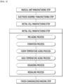
- FIG. 1 is flowchart illustrating a method for manufacturing a secondary battery according to an embodiment of the present invention.
- a method for manufacturing a secondary battery may include a radical unit manufacturing step, an electrode assembly manufacturing step, an initial cell manufacturing step, and a final cell manufacturing step.
- FIG. 2 is a perspective view illustrating a radical unit manufacturing step in the method for manufacturing the secondary battery according to an embodiment of the present invention.
- FIG. 3 is a front view illustrating the radical unit manufacturing step in the method for manufacturing the secondary battery according to an embodiment of the present invention.
- a radical unit 10 may be a stacked unit of an electrode and a separator 13. That is, the electrode and the separator 13 are sequentially stacked to form one radical unit 10, and when a plurality of radical units 10 are stacked, an electrode stack 20 may be formed.
- the radical unit manufacturing step may be a step of applying an adhesive 14 to at least one surface of the electrode and the separator 13 to manufacture the radical unit 10 in which the electrode and the separator 13 adhere to each other.
- the radical unit manufacturing step may include a step of unwinding a lower separator sheet 111 from a lower separator reel 110.
- the radical unit manufacturing step may include a step of applying an adhesive 14 to at least a portion of one surface of the unwound lower separator sheet 111, which faces an upper side, through a first nozzle 211.
- the first nozzle 211 may apply the adhesive 14 in the form of a plurality of dots.
- a step of sealing a first electrode 11 on one surface of the lower separator sheet 111 to which the adhesive 14 is applied by the first nozzle 211 may be followed.
- the first electrode 11 is configured so that a sheet of the first electrode 11 unwound from a first electrode reel 11-1 is cut to a predetermined size so as to be seated on one surface of the lower separator sheet 111.
- the first electrode 11 and the lower separator may adhere to each other by the adhesive 14 applied by the first nozzle 211.
- the method for manufacturing the secondary battery according to the embodiment of the present invention may include a step of unwinding an upper separator sheet 121 from an upper separator reel 120.
- a step of applying the adhesive 14 to at least a portion of one surface of the unwound upper separator sheet 121, which is in contact with the first electrode 11, through a second nozzle 212 may be performed.
- the second nozzle 212 may apply the adhesive 14 in the form of a plurality of dots.
- one surface and the other surface of the upper separator sheet 121 may be inverted to each other.
- the adhesive 14 is applied in a form that falls from an upper side to a lower side, and the one surface of the upper separator sheet 121, which is in contact with the first electrode 11, faces the lower side in order to be in contact with the first electrode 11, and thus, the state when the adhesive 14 is applied and the state when the adhesive 14 adheres to the first electrode 11 may be forms that are inverted upside down.
- a step of applying the adhesive 14 to at least a portion of the other surface of the upper separator sheet 121, which face the upper side, through a third nozzle 213 may be performed. That is, the third nozzle 213 may apply the adhesive 14 to an upper portion of the stack, in which the lower separator sheet 111, the first electrode 11, and the upper separator sheet 121 are sequentially stacked upward from the lower side. In this case, the third nozzle 213 may apply the adhesive 14 in the form of a plurality of dots.
- the radical unit manufacturing step may include a step of seating the second electrode 12 on the other surface of the upper separator sheet 121 to which the adhesive 14 is applied.
- the second electrode 12 may be formed by cutting a sheet of the second electrode 12, which is unwound from a second electrode reel 12-1, by using a second cutter 222.
- a four-layered structure may be formed. That is, after the step of seating the second electrode 12, the lower separator sheet 111, the first electrode 11, the upper separator sheet 121, and the second electrode 12 may be sequentially stacked to form a four-layered stack 130.
- a step in which a pressing nip roll 230 is disposed on each of both vertical surfaces of the four-layered stack 130 to apply a pressure to the four-layered stack 130 while rotating may be further performed.
- a delaminated portion within the four-layered stack 130 may be prevented from occurring by the pressure applying step due to the pressing nip roll 230.
- the electrode and the separator 13 may closely adhere to each other.
- a step of cutting the four-layered stack 130 at a predetermined interval by using the cutter to form the radical unit 10 may be further performed.
- a portion of the upper separator sheet 121 and a portion of the lower separator sheet 111, which are disposed at a spaced portion between the electrodes, may be cut using a third cutter 223 to manufacture the radical unit 10.
- the adhesive 14 may be previously applied whenever the electrode is seated on the separator sheets 111 and 121 to prevent the electrode from being displaced even if the expensive separator is not used.
- a defective rate in the process caused by high-temperature heat and a high pressure may be reduced.
- a unit cell manufacturing apparatus may be reduced in volume, and the manufacturing process may be simplified.
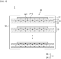
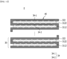
- FIG. 4 is a cross-sectional view of the electrode assembly 1 formed by stacking the radical units 10 manufactured through the radical unit manufacturing step in the method for manufacturing the secondary battery according to Embodiment 1 of the present invention.
- FIG. 5 is a cross-sectional view of an electrode assembly formed by stacking radical units manufactured through the radical unit manufacturing step in the method for manufacturing the secondary battery according to another embodiment of the present invention.
- the electrode assembly manufacturing step may be a step of attaching a fixing tape 50 to a circumference of the electrode stack 20 formed by stacking the plurality of radical units 10 to manufacture the electrode assembly 1.
- the electrode assembly manufacturing step may be performed separately from the above-mentioned radical unit manufacturing step, or the above-mentioned radial unit manufacturing step may be included in the electrode assembly manufacturing step.
- the electrodes 11 and 12 and the separator 13 may be in a state of adhering to each other by the adhesive 14. As a result, the electrodes 11 and 12 and the separator 13 may be maintained in alignment by adhesion force of the adhesive 14.
- the relative positions of the radical units 10, which are stacked may be fixed by the fixing tape 50 attached to the outside of the radical units 10. That is, the stacked alignment state of the radical units 10 can be maintained by fixing force of the fixing tape 50.
- the state of the stack before attaching the fixing tape 50 may be called the electrode stack 20, and the state of the stack after attaching the fixing tape 50 may be called the electrode assembly 1.
- the adhesive 14 may be disposed at the same position between the electrodes 11 and 12 and the separator 13.
- the adhesive 14 located between the lower portion of the first electrode 11 and the separator 13, and the adhesive 14 located between the upper portion of the first electrode 11 and the separator 13 may be arranged on the same vertical line with respect to the bottom surface, and the interval at which the adhesive 14 is disposed may be equal to each other. This can be similarly explained even in the case of the adhesive 14 located between the second electrode 12 and the separator 13.
- the adhesive 14 is disposed at the same position between the electrodes 11 and 12 and the separator 13, which has the advantage that the process time and efficiency can be increased.
- the adhesive 14 may be disposed between the electrodes 11 and 12 and the separator 13, and the adhesive 14 disposed in layers adjacent to each other may be disposed in a crossed manner.
- a first adhesive 14-1 located between the lower portion of the first electrode 11 and the separator 13, and a second adhesives 14-2 located between the upper portion of the first electrode 11 and the separator 13 may be disposed to cross each other.
- the positions of the first adhesive 14-1 and the second adhesive 14-2 only cross each other, and the applied intervals may be equal to each other. This can be similarly explained even in the case of the adhesive 14 located between the second electrode 12 and the separator 13.
- the first adhesive 14-1 and the second adhesive 14-2 may be disposed to cross each other.
- a separate nozzle is additionally disposed in addition to the first nozzle 211, the second nozzle 212, and the third nozzle 213, so that the first adhesive 14-1 and the second adhesive 14-2 may be disposed to cross each other. More specifically, a separate nozzle is disposed at a position different from the first nozzle 211, the second nozzle 212, and the third nozzle 213, so that one of the first adhesive 14-1 and the second adhesive 14-2 is applied from the first nozzle 211, the second nozzle 212, and the third nozzle 213. Further, the other one of the first adhesive 14-1 and the second adhesive 14-2 is applied from the separate nozzle, so that the first adhesive 14-1 and the second adhesive 14-2 may be disposed to cross each other.
- the present invention is not limited thereto, and a structure in which the first adhesive 14-1 and the second adhesive 14-2 is disposed to cross each other may be applied by various methods to perform manufacture.
- the adhesive 14 is disposed between the electrodes 11 and 12 and the separator 13, while the adhesive 14 disposed in layers adjacent to each other is disposed in a crossed manner, so that an increase in the thickness of the electrode assembly 2 due to the adhesive 14 can be minimized.
- the adhesives 14 disposed in layers adjacent to each other cross each other, and thus, the adhesive 14 can be more easily dissolved in the electrolyte solution contained in the initial cell 0 described later.
- the radical unit manufacturing step and the electrode assembly manufacturing step will be mainly described below.
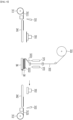
- FIGS. 6 to 9 are schematic views illustrating a radical unit manufacturing step of a method for manufacturing the secondary battery according to another embodiment of the present invention.
- the radical unit 30 may be a unit in which the separator 322 is folded to cover the electrode 31, and the electrode 31 and the separator 322 are stacked. That is, the radical unit 30 may be configured such that one side and the other side of the separator 322 are sequentially folded to cover the electrode 31, while the electrode 31 and the separator 322 are sequentially stacked.
- a electrode stack 40 in which the radical unit 10 is repeatedly formed a plurality of times can be manufactured.
- the method for manufacturing the secondary battery according to the embodiment of the present invention includes: a step of unwinding electrode sheets 3111 and 3121 from electrode reels 311 and 312 to form a plurality of electrodes 31 from the electrode sheets 3111 and 3121; a step of unwinding the electrode 31 and the stacked separator 322 from a separator reel 321; a step of seating the separator 322 on an upper surface of a table 36; and a step of applying the adhesive to at least a portion of one surface of the separator 322 seated on the table 36 and the electrode 31, through a nozzle 37, wherein the electrode 31 includes a first electrode 3112 and a second electrode 3112.
- a first cutter 331 cuts the first electrode sheet 3111 to form a plurality of first electrodes 3112. Then, when the first transfer device 341 transfers the first electrode 3112, a first header 351 adsorbs the first electrode 3112.
- the first nozzle 371 may apply an adhesive to at least a portion of the first area 3221 of the separator 3222.
- the first nozzle 371 may apply an adhesive in the form of a plurality of dots.
- the table 36 can move towards the first transfer device 341, and the first header 351 on which the first electrode 3112 is adsorbed can also move toward the table 36.
- the present invention is not limited thereto, the table 36 can be fixed.
- the first header 351 can seat the first electrode 3112 in the first area 3221 of the separator 322 to which the adhesive is applied, as shown in FIG. 6 .
- an adhesive is not applied to the first area 3221 of the separator 322, but an adhesive may be previously applied to the lower portion of the first electrode 3112. That is, in a state in which the adhesive is previously applied to the lower portion of the first electrode 3112, the first electrode 3112 can be seated on the first area 3221 of the separator 322 by the first header 351.
- the method for manufacturing the secondary battery according to the embodiment of the present invention further includes a folding step after the step of applying the adhesive.
- the folding step when the first electrode 3112 is seated on the separator 322, one side of the separator 322 can be folded to cover the first electrode 3112, and when the second electrode 3122 is seated on the separator 322, the other side of the separator 322 can be folded to cover the second electrode 3122.
- the table 36 moves toward the second transfer device 342 that transfers the second electrode 3122. Then, one side of the separator 322 can be folded, and the second area 3222 of the separator 322 can cover the first electrode 3112.
- an adhesive may be previously applied to the upper portion of the first electrode 3112 or the second area 3222 of the separator 322 by the first nozzle 371.
- the second cutter 332 may cut the second electrode sheet 3121 to form a plurality of second electrodes 3122. Thereafter, when the second transfer device 342 transfers the second electrode 3122, the second header 352 adsorbs the second electrode 3122.
- a second nozzle 372 located on the upper side of the second area 3122 applies an adhesive to at least a portion of the second area 3222 of the separator 322.
- the second nozzle 372 may apply an adhesive in the form of a plurality of dots.
- the table 36 can move toward the second transfer device 342, and the second header 352 on which the second electrode 3122 is adsorbed may also move toward the table 36.
- the present invention is not limited thereto, and the table 36 may be fixed.
- the second header 352 may seat the second electrode 3122 in the second area 3222 of the separator 322 to which the adhesive is applied, as shown in FIG. 8 .
- an adhesive is not applied to the second area 3222 of the separator 322, and an adhesive may be previously applied to the lower portion of the second electrode 3122. That is, in a state in which the adhesive is previously applied to the lower portion of the second electrode 3122, the second electrode 3122 may be seated on the second area 3222 of the separator 322 by the second header 352.
- the table 36 moves toward the first transfer device 341 that transfers the first electrode 3112.
- the present invention is not limited thereto, and the table 36 may be fixed.
- the other side of the separator 322 may be folded, so that the first area 3221 of the separator 322 may cover the second electrode 3122.
- an adhesive may be previously applied to the upper portion of the second electrode 3122 or the first area 3221 of the separator 322 by the second nozzle 372.
- a first nozzle 371 located on the upper side of the first area 3221 applies an adhesive to at least a portion of the first area 3221 of the separator 322.
- the first nozzle 371 may apply an adhesive in the form of a plurality of dots.
- the radical unit can be manufactured by the method for manufacturing the secondary battery according to the embodiment of the present invention.
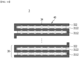
- FIG. 10 is a cross-sectional view of an electrode assembly is manufactured by repeatedly forming the radical unit manufactured through the radical unit manufacturing step in the method for manufacturing the secondary battery according to another embodiment of the present invention.
- FIG. 11 is a cross-sectional view of an electrode assembly is manufactured by repeatedly forming the radical unit manufactured through the radical unit manufacturing step in the method for manufacturing the secondary battery according to another embodiment of the present invention.
- the electrode assembly manufacturing step may be a step of manufacturing the electrode assembly 3 by attaching a fixing tape 50 to a circumference of an electrode stack 40, in which a plurality of radical units 30 are repeatedly formed a plurality of times, as in the electrode laminate 20 of FIG. 4 .
- the electrode assembly 3 may omit the fixing tape 50 as shown in FIG. 10 .
- one end of the separator 322 may surround a portion of the outer surface of the electrode stack 40.
- the electrode assembly manufacturing step may be performed separately from the above-mentioned radical unit manufacturing step, or the above-mentioned radical unit manufacturing step may be included in the electrode assembly manufacturing step.
- the radical unit 30 of the embodiment of the present invention may be in a state in which the electrodes 3112 and 3122 and the separator 322 are adhered to each other with an adhesive 34. Thereby, the electrodes 3112 and 3122 and the separator 322 can be maintained in alignment by adhesive force of the adhesive 34.
- the electrode stacks 40 of the embodiment of the present invention is configured such that the separator 322 covers the upper and lower portions and one side surface of the electrodes 3112 and 3122, and thus, can maintain the stacked alignment state of the radical units 30 even without a separate fixing tape 50 as shown in FIG. 4 .
- the fixing tape 50 of FIG. 4 is attached to the outside of the electrode stack 40 of this embodiment or one end of the separator 322 is wrapped around the outside, the stacked alignment state of the radical units 30 can be more stably maintained.
- the adhesive 34 may be disposed at the same position between the electrodes 3112 and 3122 and the separator 322.
- the adhesive 34 located between the lower portion of the first electrode 3112 and the separator 322 and the adhesive 34 located between the upper portion of the first electrode 3112 and the separator 322 may be disposed on the same vertical line with respect to the bottom surface, respectively, and the interval at which the adhesive 34 is disposed may be equal to each other. This may be similarly explained even in the case of the adhesive 34 located between the second electrode 3122 and the separator 322.
- the adhesive 34 is disposed at the same position between the electrodes 3112 and 3122 and the separator 322, which has the advantage that the process time and efficiency can be increased.
- the adhesive 34 may be disposed between the electrodes 3112 and 3122 and the separator 322, and the adhesives 34 disposed in layers adjacent to each other may be disposed in a crossed manner.
- a first adhesive 34-1 located between the lower portion of the first electrode 3112 and the separator 322, and a second adhesives 34-2 located between the upper portion of the first electrode 3112 and the separator 322 may be disposed to cross each other.
- the positions of the first adhesive 34-1 and the second adhesive 34-2 are only crossed each other, and the intervals at which they are applied can be equal to each other. This may be similarly explained even in the case of the adhesive 14 located between the second electrode 3122 and the separator 322.
- the first adhesive 34-1 and the second adhesive 34-2 may be disposed to cross each other.
- a separate nozzle may be additionally disposed in addition to the first nozzle 371 and the second nozzle 372, so that the first adhesive 34-1 and the second adhesive 34-2 can be disposed to cross each other. More specifically, the separate nozzle is disposed at a position different from the first nozzle 371 and the second nozzle 372, so that one of the first adhesive 34-1 and the second adhesive 34-2 is applied from the first nozzle 371 and the second nozzle 372, and the other one of the first adhesive 34-1 and the second adhesive 34-2 is applied from the separate nozzle, so that the first adhesive 34-1 and the second adhesive 34-2 can be disposed to cross each other.
- the present invention is not limited thereto, and a structure in which the first adhesive 34-1 and the second adhesive 34-2 is disposed to cross each other may be applied by various methods to perform manufacture.
- the adhesive 34 is disposed between the electrodes 3112 and 3122 and the separator 322, and the adhesives 34 disposed in layers adjacent to each other are disposed in a crossed manner, so that an increase in the thickness of the electrode assembly 4 due to the adhesive 34 can be minimized.
- the adhesives 34 disposed in layers adjacent to each other cross each other, and thus, the adhesives 34 can be more easily dissolved in the electrolyte solution contained in the initial cell 0 described later.
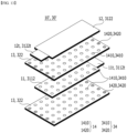
- FIGS. 12 and 13 are exploded perspective views of a radical unit manufactured through the radical unit manufacturing step in the method for manufacturing the secondary battery according to another embodiment of the present invention.
- the radical unit 10 may have a structure in which the separator 13, the first electrode 11, the separator 13, and the second electrode 12 are alternately stacked as shown in FIGS. 2 to 5 .
- the separator 13 located under the first electrode 11 is called an upper separator
- the separator 13 located under the second electrode 12 is called an upper separator.
- the radical unit is in a zigzag shape in which the separator 322 is folded to cover the electrodes 3112 and 3122, and may have a structure in which a first electrode 3112, a separator 322, and a second electrode 3122 are alternatively stacked.
- the surface on which the separator 322 is folded is omitted.
- first electrode tabs 11t and 3112t may be formed at one end of the first electrodes 11 and 3112
- second electrode tabs 12t and 3122t may be formed at one end of the second electrodes 12 and 3122.
- the first electrodes 11 and 3112 and the second electrodes 12 and 3122 may be disposed such that the first electrode tabs 11t and 3112t and the second electrode tabs 12t and 3122t face different directions.
- adhesive layers 14 and 34 may be formed between the first electrodes 11 and 3112 and the separators 13 and 322 and between the second electrodes 13 and 3122 and the separators 12 and 322.
- the adhesive layers 14 and 34 may be formed by applying an adhesive in the form of a plurality of dots as shown in FIG. 12 . Further, the plurality of dots may be arranged at regular intervals. Further, the adhesive layers 14 and 34 may include an adhesive component that is dissolved in the electrolyte solution contained in the initial cell 0 described later.
- the adhesive layers 14 and 34 are arranged in the form of a plurality of dots, and can be more easily dissolved in the electrolyte solution.
- the adhesive layers 14 and 34 include an adhesive component dissolved in the electrolyte solution, and in the final battery cell, the adhesive layers 14 and 34 do not remain on the surfaces of the first electrodes 11 and 3112 and the second electrodes 12 and 3122, thereby capable of preventing deterioration of cell performance due to the adhesive layers 14 and 34.
- the radical units 10' and 30' can be described almost in the same way as the radical units 10 and 30 of FIG. 12 , and the adhesive layers 14 and 34 will be mainly described below.
- the adhesive layers 14 and 34 may include first and second adhesive layers 1410 and 3410 and second adhesive layers 1420 and 3420.
- first adhesive layers 1410 and 3410 may be located between the central portion of the first electrodes 11 and 3112 and the separators 13 and 322 and between the central portion of the second electrodes 12 and 3122 and the separators 13 and 322.
- the second adhesive layers 1420 and 3420 may be located at both ends of the separators 12 and 322 adjacent to the first electrode tabs 11t and 3112t or the second electrode tabs 12t and 3122t. More specifically, the second adhesive layers 1420 and 3420 may be located between the first electrode tabs 11t and 3112t and the separators 13 and 322 and between the second electrode tabs 12t and 3122t.
- the second adhesive layers 1420 and 3420 can be formed between the first electrode tabs 11t and 3112t and the separators 13 and 322 only at the portion where the first electrode tabs 11t and 3112t and the separators 13 and 322 face each other, and can be formed between the second electrode tabs 12t and 3122t and the separators 13 and 322 only at the portion where the second electrode tabs 12t and 3122t and the separators 13 and 322 face each other.
- the first adhesive layers 1410 and 3410 and the second adhesive layers 1420 and 3420 may be formed by applying an adhesive in the form of a plurality of dots, respectively.
- the first adhesive layers 1410 and 3410 may include an adhesive component dissolved in an electrolyte solution contained in the initial cell 0 described later, similar to the adhesive layers 14 and 34 of FIG. 12 .
- the second adhesive layers 1420 and 3420 may include an adhesive component that is not dissolved in the electrolyte solution.
- first adhesive layers 1410 and 3410 and second adhesive layers 1420 and 3420 may be formed, respectively.
- a separate nozzle is additionally disposed in addition to the nozzle 21 of FIGS. 2 and 3 or the nozzle 37 of FIGS. 6 to 9 , so that first adhesive layers 1410 and 3410 and second adhesive layers 1420 and 3420 may be formed, respectively. More specifically, the separate nozzles are disposed adjacent to both ends of the separators 12 and 322, so that the first adhesive layers 1410 and 3410 are formed from the nozzle 21 of FIGS. 2 and 3 or the nozzle 37 of FIGS. 6 to 9 , and second adhesive layers 1420 and 3420 may be formed from the separate nozzle.
- first adhesive layers 1410 and 3410 and the second adhesive layers 1420 and 3420 may be formed by applying different adhesives by various methods.
- the first adhesive layers 1410 and 3410 are located between the central portions of the first electrodes 11 and 3112 and the separators 13 and 322 and between the central portion of the second electrode 12 and 3122 and the separators 13 and 322, so that in the final battery cell, the first adhesive layers 15 and 35 do not remain on the surfaces of the first electrodes 11 and 3112 and the second electrodes 12 and 3122, thereby preventing deterioration of cell performance due to the first adhesive layers 1410 and 3410.
- the second adhesive layers 1420 and 3420 are located between the first electrode tabs 11t and 3112t and the separators 13 and 322 and between the second electrode tab 12t and 3122t), so that in the final battery cell, the second adhesive layers 1420 and 3420 are not dissolved in the electrolyte solution, thereby preventing the separators 13 and 322 facing the first electrode tabs 11t and 3112t and the second electrode tabs 12t and 3122t from being folded. Further, the second adhesive layers 1420 and 3420 can prevent the first electrodes 11 and 3112 and the second electrodes 12 and 3122 from being separated from the separators 13 and 322 in the final battery cell.
- the second adhesive layers 1420 and 3420 are located between the pair of separators 13 and 322 facing each other, while they may be formed in a portion except the portion where the separators 13 and 322 and the first electrodes 11 and 3112 and/or the second electrodes 12 and 3122 come into contact.
- the second adhesive layers 1420 and 3420 are positioned between a pair of separators 13 and 322 facing each other, and can be formed in a portion excluding a portion where the separators 13 and 322 and the first electrodes 11 and 3112 and/or the second electrodes 12 and 3122 are in contact with each other. In other words, the second adhesive layers 1420 and 3420 are located between the pair of separators 13 and 322 facing each other, and do not come into contact with the first electrodes 11 and 3112 and the second electrodes 12 and 3122.
- the second adhesive layers 1420 and 3420 are formed at a position avoiding a portion where the first electrodes 11 and 31112 and/or the second electrodes 12 and 3122 comes into contact with the separators 13 and 322, so that the second adhesive layers 1420 and 3420 can prevent the first electrodes 11 and 3112 and the second electrodes 12 and 3122 from interfering with the movement of lithium ions between the separators 13 and 322. That is, the second adhesive layers 1420 and 3420 can prevent the above-mentioned separators 13 and 322 from being folded without degrading cell performance, and can prevent the first electrodes 11 and 3112 and the second electrodes 12 and 3122 from being separated from the separators 13 and 322.
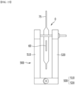
- FIG. 14 is a perspective view illustrating an initial cell manufacturing step in the method for manufacturing the secondary battery according to another embodiment of the present invention.
- FIG. 15 is a front view illustrating a formation process in a method for manufacturing a secondary battery according to an embodiment of the present invention.
- the method for manufacturing the secondary battery according to an embodiment of the present invention may include an initial cell manufacturing step after the electrode assembly manufacturing step.
- the initial cell manufacturing step may be a step of accommodating the electrode assemblies 1, 2, 3, and 4 in a pouch case 70 and injecting an electrolyte solution into the pouch case 70 to seal a pouch case edge 71, thereby manufacturing an initial cell 0.
- the pouch case 70 may include a gas pocket part 75 extending to one side of the cup part in which the electrode assemblies 1, 2, 3, and 4 are accommodated. After the electrode assemblies 1, 2, 3 and 4 and the electrolyte solution are accommodated in the cup part, the pouch case edge 71 can be sealed.
- the sealing may be performed at an edge of the cup part and an outer edge of the gas pocket part 75. That is, an edge of an area on which the cup part and the gas pocket part 75 are combined with each other may be sealed in the form of a closed curve so that the combined area of the cup part and the gas pocket part 75 is sealed from the outside. That is, after the sealing, the cup part and the gas pocket part 75 may be sealed from the outside, but may communicate with each other.
- the step of manufacturing a final cell by post-processing the initial cell 0 may be performed.
- the adhesive applied to the surface of at least one of the electrode and the separators 13 and 322 in the foregoing radical unit manufacturing step may be dissolved.
- the electrolyte solution contained in the initial cell 0 may be an organic solvent, and the meaning that the adhesive 14 is dissolved may mean that the adhesives 14 and 34 are dissolved and penetrated into the electrolyte solution, which is the organic solvent.
- the adhesives 14 and 34 applied to the surface of the electrode or separators 13 and 322 are reduced in the applied area, or the applied adhesives 14 and 34 is completely removed so as not to remain on the surface of the electrode.
- the adhesives 14 and 34 do not remain on the electrode surface.
- a portion of the adhesives 14 and 34 may be permeated into the separators 13 and 322 in that the separators 13 and 322 are generally a porous sheet.
- the adhesives 14 and 34 that have penetrated into the separators 13 and 322 may be dissolved into the electrolyte solution, and in this process, the application mark of the adhesives 14 and 34 may remain on the separators 13 and 322.
- the application mark of the adhesives 14 and 34 may mean that the components of the adhesives 14 and 34 do not remain, but a portion of the outer surfaces of the separators 13 and 322 are deformed by the adhesives 14 and 34.
- the present invention is not limited thereto, and the application mark of the adhesives 14 and 34 may mean a mark that can confirm whether the adhesives 14 and 34 are applied by various methods, such as a mark that can confirm whether the adhesives 14 and 34 are applied with the naked eye.
- the application mark of the adhesives 14 and 34 formed on the separators 13 and 322 may be formed at the same position as the position where the adhesives 14 and 34 are applied.
- the adhesives 14 and 34 for allowing the electrode and the separator to adhere to each other which is used in the method for manufacturing the secondary battery according to an embodiment of the present invention, may be an acrylate-based adhesive.
- the acrylate-based adhesives 14 and 34 it may be possible to dissolve the adhesives 14 and 34 into the electrolyte solution.
- the final cell manufacturing step may include a formation process of charging the initial cell 0 at a high temperature that is greater than room temperature to activate the initial cell 0.
- the formation process (activation process) may be a process in which an SEI layer is formed on a surface of an electrode plates of the electrode assembly through the charging process so as to be charged, and thus, the secondary battery may supply power.
- the formation process may be performed at a temperature of 45 degrees or more.
- at least a portion of the adhesives 14 and 34 may be dissolved in the formation process.
- the formation process may be performed at a temperature between 50 degrees and 70 degrees. The dissolution of the adhesive 14 is more likely to occur at a temperature of 50 degrees, which is higher than 45 degrees. Also, it may be undesirable because the performance of the cell product is deteriorated at a temperature of 70 degrees or more.
- the formation process may include a jig pressing process of pressing both side surfaces of an initial cell 0 by using a jig 500.
- a left side of the initial cell 0 may be pressed using a left jig 510
- a right side of the initial cell 0 may be pressed using the right jig 520.
- a gas generated inside the electrode assemblies 1, 2, 3 and 4 may smoothly move to the gas pocket part 75.
- the gas moving to the gas pocket part 75 may be smoothly discharged to the outside of the cell in a subsequent degassing process. If the jig pressing process is performed during the formation process, the process of dissolving the adhesive 14 in the electrolyte solution may be easily performed.
- the jig pressing process may include a process of applying and releasing a pressure of the jig 500 to/from both side surfaces of the initial cell 0. That is, a process of one cycle, in which the jig 500 applies and releases a pressure to/from the initial cell 0 is repeated at least twice.
- the process of one cycle in which the pressure of the jig 500 is applied and released may be a process of directly applying physical force to the adhesives 14 and 34 by alternately applying positive and negative pressures during dissolution. Therefore, it is possible to obtain an effect of allowing the dissolution of the adhesives 14 and 34 to significantly well occur.
- a control device may be connected to a jig device for more systematic operation.
- a positive pressure time and a negative pressure time may be adjusted, and an intensity of the positive pressure and an intensity of the negative pressure may also be controlled. Therefore, a more effective adhesive dissolution system can be implemented.
- the formation process may include a jig pressing process which is performed at a temperature of 55 degrees to 65 degrees and presses both side surfaces of the initial cell 0 by using the jig 500.
- the adhesive 14 is completely dissolved in the formation process, and thus, a mark of the adhesives 14 and 34 do not remain on the surface of the electrode.
- the application mark of the adhesives 14 and 34 may remain on the separators 13 and 322.
- an area on which the adhesives 14 and 34 remains may become a non-reaction area on which an electrode reaction does not occur, and thus the battery performance may be deteriorated.
- the non-reaction area due to the adhesives 14 and 34 may be disappeared to prevent the performance from being deteriorated, thereby realizing excellent battery performance.
- the final cell manufacturing step in the method for manufacturing the secondary battery according to the embodiment of the present invention may further include a pre-aging process of storing the initial cell 0 at room temperature before the formation process.
- the pre-aging process at room temperature may be performed for about 1.5 days.
- the pre-aging process may be a process that gives time so that the electrolyte is sufficiently impregnated between the electrode and the separators 13 and 322.
- at least a portion of the adhesives 14 and 34 may be dissolved even in the pre-aging process.
- the final cell manufacturing step in the method for manufacturing the secondary battery according to the embodiment of the present invention may further include a room-temperature aging process of storing the initial cell 0 at room temperature after the formation process.
- the room-temperature aging process may be performed for about 1 day.
- the final cell manufacturing step may further include a high-temperature aging process of storing the initial cell 0 at a temperature of 60 degrees to 65 degrees after the room temperature aging process and before the degassing process.
- the final cell manufacturing step in the method for manufacturing the secondary battery according to the embodiment of the present invention may include the degassing process after the high-temperature aging process.
- the degassing process may be a process of discharging the internal gas of the initial cell 0 to the outside.
- the gas discharged in the degassing process may be the internal gas that is mainly generated in the formation process and stored in the gas pocket part 75.
- a through-hole may be formed in the gas pocket part 75 to allow the gas to be discharged to the outside.
- the final cell manufacturing step may include a re-sealing process of re-sealing the initial cell 0 so as to be sealed from the outside again after the degassing process.
- the final cell manufacturing step may manufacture the final cell.
- the adhesives 14 and 34 may be dissolved so as not to remain on the surface of the internal electrode or the separators 13 and 322 of the manufactured final cell. In particular, as described above, the application mark of the adhesives 14 and 34 may remain on the separators 13 and 322.
- the method for manufacturing the secondary battery according to the embodiment of the present invention may further include a finish charging/discharging step of charging and discharging the final cell after the final cell manufacturing step.
- the final charge/discharge step may include a process of measuring a battery capacity of the final cell and may include a process of finally charging the battery to a set voltage for shipment of the final product.
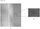
- a battery cell was manufactured accommodating an electrode assembly, in which a positive electrode, a negative electrode, and a separator were alternately stacked, together with an electrolyte solution.
- the adhesive was applied in the form of a plurality of dots between the positive electrode and the separator and between the negative electrode and the separator.
- the separator is CCS (Ceramic Coated Separator)
- the adhesive includes an acrylate-based adhesive material
- the electrolyte solution may be a standard electrolyte solution in which ethylene carbonate (EC) and ethylmethyl carbonate (EMC) are mixed in a ratio of 3:7.
- FIG. 16 (a) is an image confirmed with the naked eye
- FIG. 16 (b) is an image taken by magnifying it with a microscope.
- FIGS. 16 (a) and (b) in the separator separated from the charged battery cell, it can be confirmed that the adhesive leaves a mark on the separator. In particular, when magnified and photographed with a microscope enlarged as shown in FIG. 16(b) , it can be confirmed that an application mark of the adhesive left on the separator are more easily observed.
- the adhesive was applied between the positive electrode and the separator and between the negative electrode and the separator in the electrode assembly unit through the application mark of the adhesive left on the outer surface of the separator.
Abstract
The method for manufacturing the secondary battery according to the present invention includes: manufacturing an electrode assembly by alternately stacking an electrode and a separator, applying an adhesive to at least one surface of the electrode and the separator to adhere the electrode and the separator to each other; and manufacturing a battery cell by accommodating the electrode assembly together with an electrolyte solution in a pouch case and sealing the pouch case, wherein at least portion of the adhesive is dissolved in the electrolyte solution, and thereby a mark, which the adhesive was applied to, is formed on the separator.
Description
- This application claims the benefit of
Korean Patent Application No. 10-2020-0155000 on November 18, 2020 Korean Patent Application No. 10-2021-0124053 on September 16, 2021 - The present invention relates to a secondary battery and a method for manufacturing the same, which is a method for preventing an electrode or a separator from being separated from a fixed position when manufacturing a unit cell by stacking the electrode and the separator, and more particularly, to a secondary battery and a method for manufacturing the same, which is capable of reducing production costs, reducing a defective rate in a process, which is caused by high-temperature heat and a high pressure, and preventing performance of the battery from being deteriorated, when compared to a method for manufacturing a radical unit cell through a lamination according to the related art.
- In general, secondary batteries include nickel-cadmium batteries, nickel-hydrogen batteries, lithium ion batteries, and lithium ion polymer batteries. Such a secondary battery is being applied to and used in small-sized products such as digital cameras, P-DVDs, MP3Ps, mobile phones, PDAs, portable game devices, power tools, E-bikes, and the like as well as large-sized products requiring high power such as electric vehicles and hybrid vehicles, power storage devices for storing surplus power or renewable energy, and backup power storage devices.
- In order to manufacture such a secondary battery, first, electrode active material slurry is applied to a positive electrode collector and a negative electrode collector to manufacture a positive electrode and a negative electrode, and then, the electrodes are laminated on both sides of a separator, thereby forming an electrode assembly having a predetermined shape. Further, the electrode assembly is accommodated in a battery case, an electrolyte solution is injected therein and then the battery case is sealed.
- The electrode assembly is classified into various types. For example, the electrode assembly is classified into a simple stack type, in which a positive electrode, a separator, and a negative electrode are simply and continuously stacked to cross each other without manufacturing a unit cell, a lamination & stack (L&S) type, in which unit cells are manufactured using positive electrodes, separators, and negative electrodes and then are stacked, a stack & folding (S&F) type, in which a plurality of electrodes or unit cells are attached to be separated from each other on one surface of a separator sheet, of which one side is long, and then the separator sheet is repeatedly folded from one end thereof in the same direction, and a Z-folding type, in which a plurality of electrodes or unit cells are alternately attached on one surface and the other surface of a separator sheet, of which one side is long, and then a process, in which the separator sheet is folded from one end thereof in a specific direction and then folded in an opposite direction, is alternately and repeatedly performed.
- Among them, in order to manufacture the lamination & stack type electrode assembly, the stack & fold type electrode assembly, or the Z-folding type electrode assembly, the unit cell may be manufactured first. In general, in order to manufacture the unit cell, the separator may be stacked on each of top and bottom surfaces of a center electrode, and then an upper electrode may be further stacked at the uppermost end. In addition, a laminating process in which heat and a pressure are applied to the stack, in which the electrode and the separator are stacked, may be performed. Since the lamination process is performed, the electrode and the separator may be bonded to each other to firmly form the unit cell.
- However, in the related art, the electrode and the separator are not bonded to each other until the lamination process is performed on the stack, in which the electrode and the separator are stacked, but are only in contact with each other. Therefore, in order to perform the laminating process, there is a problem that the electrode is separated from a fixed position in the process of transferring the stack. In addition, since the laminating process applies high-temperature heat and a high pressure to the stack, the electrode may be damaged. Furthermore, recently, a separator capable of adhering to an electrode even with low-temperature heat and a low pressure has been developed, but the separator consumes an excessively high manufacturing cost, which is not economical and also deteriorates process efficiency.
- As a way to solve this problem, a method for manufacturing an adhesive is considered, but in this case, the adhesive exists on the surface of the electrode so as not to exert a proper function of the electrode at a corresponding portion, thereby deteriorating battery performance.
- The present invention has been devised to solve the above problems, and an object of the present invention is to provide a secondary battery and a method for manufacturing the same, which is capable of preventing an electrode or a separator from being separated from a fixed position when manufacturing a unit cell by stacking the electrode and the separator.
- In particular, an object of the present invention is to provide a secondary battery and a method for manufacturing the same, which is capable of reducing production costs, reducing a defective rate in a process, which is caused by high-temperature heat and a high pressure, and preventing performance of the battery from being deteriorated, when compared to a method for manufacturing a radical unit cell through a lamination according to the related art.
- A method for manufacturing a secondary battery according to the present invention comprises manufacturing an electrode assembly by alternately stacking an electrode and a separator and applying an adhesive to at least one surface of the electrode and the separator to adhere the electrode and the separator to each other; and manufacturing a battery cell by accommodating the electrode assembly together with an electrolyte solution in a pouch case and sealing the pouch case, wherein at least portion of the adhesive is dissolved in the electrolyte solution, and thereby a mark, which the adhesive was applied to, is formed on the separator.
- The step of manufacturing the battery cell may further comprise a formation process of charging the battery cell at a temperature that is higher than a room temperature to activate the battery cell, wherein the at least portion of the adhesive may be dissolved in the electrolyte solution in the formation process.
- The formation process may be performed at a temperature of 50 degrees Celsius or more and 70 degrees Celsius or less.
- The formation process may further comprise a process of compressing both side surfaces of the initial cell by using a jig.
- The formation process may be performed at a temperature of 55 degrees Celsius or more and 65 degrees Celsius or less, and the adhesive may be completely dissolved in the electrolyte solution in the formation process so that the adhesive is removed from a surface of the electrode.
- The adhesive may be an acrylate-based adhesive, and the electrolyte solution may be an organic solvent.
- The secondary battery manufacturing method may further comprise manufacturing a radical unit, wherein the radical unit may be a unit which the electrode and the separator are stacked, wherein the electrode assembly may be manufactured by attaching a fixing tape around an electrode stack, in which a plurality of radical units are stacked.
- The step of manufacturing the radical unit may comprise: unwinding a lower separator from a lower separator reel; applying the adhesive to at least portion of one surface of the unwound lower separator, which faces an upper side, through a first nozzle; positioning a first electrode on one surface of the lower separator to which the adhesive is applied; unwinding an upper separator from an upper separator reel; applying the adhesive to at least portion of one surface of the unwound upper separator, which is in contact with the first electrode, through a second nozzle; applying the adhesive to at least portion of the other surface of the upper separator, which faces the upper side, through a third nozzle; and positioning a second electrode on the other surface of the upper separator, to which the adhesive is applied, after applying the adhesive through the third nozzle.
- The first nozzle, the second nozzle, and the third nozzle may apply the adhesive in a form a plurality of dots.
- The secondary battery manufacturing method may further comprise manufacturing a radical unit, wherein the radical unit is a unit which the electrode and the separator are stacked, the separator being folded to cover the electrode, wherein the electrode assembly is manufactured by repeatedly forming the radical unit.
- The step of manufacturing the radical unit may comprise: unwinding an electrode sheet from an electrode reel to form a plurality of electrodes from the electrode sheet; unwinding the separator to be stacked with the electrode, from a separator reel; positioning the separator on an upper surface of a table; and applying the adhesive to at least portion of the separator which is positioned on the table and the electrode, through a nozzle, wherein the electrode comprises a first electrode and a second electrode.
- The method may further comprise a folding step after the step of applying the adhesive, wherein in the folding step, when the first electrode is positioned on the separator, one side of the separator may be folded to cover the first electrode, and when the second electrode is positioned on the separator, the other side of the separator may be folded to cover the second electrode.
- The nozzle may apply the adhesive in a form a plurality of dots.
- A secondary battery according to the present invention may comprise an electrode assembly in which an electrode and a separator are alternately stacked; and a pouch case for accommodating the electrode assembly together with the electrolyte solution, wherein a mark, which at least one adhesive was applied to, remains on a surface of the separator, which is in contact with the electrode, and the mark, which the adhesive was applied to, is a mark in which the first adhesive layer having been formed between the electrode and the separator was dissolved into the electrolyte solution.
- The first adhesive layer may be formed by applying the adhesive in a form of a plurality of dots, and the mark, which the adhesive was applied to, is formed in the form of dots at a position where the first adhesive layer is formed.
- The adhesive may be an acrylate-based adhesive, and the electrolyte solution may be an organic solvent.
- The electrode may comprise a first electrode and a second electrode, the separator may comprise an upper separator and a lower separator, and the electrode assembly may have a structure in which the lower separator, the first electrode, the upper separator, and the second electrode are alternately stacked.
- The electrode may comprise a first electrode and a second electrode, and the electrode assembly may be configured such that: the first electrode is positioned on the separator, and one side of the separator is folded to cover the first electrode, and the second electrode is positioned on the separator, and the other side of the separator is folded to cover the second electrode.
- An electrode tab may be formed at one end of the electrode, a second adhesive layer may be formed between the electrode tab and the separator, and the second adhesive layer may comprise an adhesive component that is not dissolved into the electrolyte solution.
- The second adhesive layer may be formed by applying the adhesive in a form of a plurality of dots.
- The secondary battery and the method for manufacturing the same according to the present invention are configured such that an electrode assembly, in which an electrode and a separator are alternately stacked, and an adhesive is applied to at least one surface of the electrode and the separator to allow the electrode and the separator to adhere to each other, is accommodated together with an electrolyte solution in a pouch case, wherein while at least a portion of the adhesive is dissolved in the electrolyte solution, an application mark of the adhesive is formed on the separator, and the application mark of the adhesive does not include a component of the adhesive.
- Therefore, the secondary battery and the method for manufacturing the same can prevent the electrode or the separator from being separated from a fixed position by the adhesive when manufacturing an electrode assembly by stacking an electrode and a separator. In addition, it is possible to prevent performance deterioration of the battery due to the adhesive by being dissolved the adhesive in the electrolyte solution in the battery cell.
-
-
FIG. 1 is flowchart illustrating a method for manufacturing a secondary battery according to an embodiment of the present invention. -
FIG. 2 is a perspective view illustrating a radical unit manufacturing step in the method for manufacturing the secondary battery according to an embodiment of the present invention. -
FIG. 3 is a front view illustrating the radical unit manufacturing step in the method for manufacturing the secondary battery according to an embodiment of the present invention. -
FIG. 4 is a cross-sectional view of an electrode assembly formed by stacking radical units manufactured through the radical unit manufacturing step in the method for manufacturing the secondary battery according to an embodiment of the present invention. -
FIG. 5 is a cross-sectional view of an electrode assembly formed by stacking radical units manufactured through the radical unit manufacturing step in the method for manufacturing the secondary battery according to another embodiment of the present invention. -
FIGS. 6 to 9 are schematic views illustrating the radical unit manufacturing step in the method for manufacturing the secondary battery according to another embodiment of the present invention. -
FIG. 10 is a cross-sectional view of an electrode assembly is manufactured by repeatedly forming the radical unit manufactured through the radical unit manufacturing step in the method for manufacturing the secondary battery according to another embodiment of the present invention. -
FIG. 11 is a cross-sectional view of an electrode assembly is manufactured by repeatedly forming the radical unit manufactured through the radical unit manufacturing step in the method for manufacturing the secondary battery according to another embodiment of the present invention. -
FIGS. 12 and13 are exploded perspective views of a radical unit manufactured through the radical unit manufacturing step in the method for manufacturing the secondary battery according to another embodiment of the present invention. -
FIG. 14 is a perspective view illustrating an initial cell manufacturing step in the method for manufacturing the secondary battery according to another embodiment of the present invention. -
FIG. 15 is a front view illustrating a formation process in a method for manufacturing a secondary battery according to an embodiment of the present invention. -
FIG. 16 is a view showing an application mark of the adhesive remaining on the surface of the separator. - Hereinafter, preferred embodiments of the present invention will be described in detail with reference to the accompanying drawings so that those of ordinary skill in the art can easily carry out the present invention. However, the present invention may be implemented in several different forms and is not limited or restricted by the following examples.
- In order to clearly explain the present invention, detailed descriptions of portions that are irrelevant to the description or related known technologies that may unnecessarily obscure the gist of the present invention have been omitted, and in the present specification, reference symbols are added to components in each drawing. In this case, the same or similar reference numerals are assigned to the same or similar elements throughout the specification.
- Also, terms or words used in this specification and claims should not be restrictively interpreted as ordinary meanings or dictionary-based meanings, but should be interpreted as meanings and concepts conforming to the scope of the present invention on the basis of the principle that an inventor can properly define the concept of a term to describe and explain his or her invention in the best ways.
-
FIG. 1 is flowchart illustrating a method for manufacturing a secondary battery according to an embodiment of the present invention. - Referring to
FIGS. 1 to 3 , a method for manufacturing a secondary battery according to an embodiment of the present invention may include a radical unit manufacturing step, an electrode assembly manufacturing step, an initial cell manufacturing step, and a final cell manufacturing step. - In the method for manufacturing a secondary battery according to an embodiment of the present invention, a radical unit manufacturing step and an electrode assembly manufacturing step will be mainly described below.
-
FIG. 2 is a perspective view illustrating a radical unit manufacturing step in the method for manufacturing the secondary battery according to an embodiment of the present invention.FIG. 3 is a front view illustrating the radical unit manufacturing step in the method for manufacturing the secondary battery according to an embodiment of the present invention. - First, in the embodiment of the present invention, a
radical unit 10 may be a stacked unit of an electrode and aseparator 13. That is, the electrode and theseparator 13 are sequentially stacked to form oneradical unit 10, and when a plurality ofradical units 10 are stacked, anelectrode stack 20 may be formed. - In the method for manufacturing the secondary battery according to the embodiment of the present invention, the radical unit manufacturing step may be a step of applying an adhesive 14 to at least one surface of the electrode and the
separator 13 to manufacture theradical unit 10 in which the electrode and theseparator 13 adhere to each other. - Referring to
FIGS. 2 and3 , the radical unit manufacturing step may include a step of unwinding alower separator sheet 111 from alower separator reel 110. In addition, the radical unit manufacturing step may include a step of applying an adhesive 14 to at least a portion of one surface of the unwoundlower separator sheet 111, which faces an upper side, through afirst nozzle 211. Thefirst nozzle 211 may apply the adhesive 14 in the form of a plurality of dots. Next, a step of sealing afirst electrode 11 on one surface of thelower separator sheet 111 to which the adhesive 14 is applied by thefirst nozzle 211, may be followed. Thefirst electrode 11 is configured so that a sheet of thefirst electrode 11 unwound from a first electrode reel 11-1 is cut to a predetermined size so as to be seated on one surface of thelower separator sheet 111. Thefirst electrode 11 and the lower separator may adhere to each other by the adhesive 14 applied by thefirst nozzle 211. - In addition, the method for manufacturing the secondary battery according to the embodiment of the present invention may include a step of unwinding an
upper separator sheet 121 from anupper separator reel 120. When theupper separator sheet 121 is unwound, a step of applying the adhesive 14 to at least a portion of one surface of the unwoundupper separator sheet 121, which is in contact with thefirst electrode 11, through asecond nozzle 212 may be performed. Thesecond nozzle 212 may apply the adhesive 14 in the form of a plurality of dots. - Referring to
FIG. 2 , after thesecond nozzle 212 applies the adhesive 14 to one surface of theupper separator sheet 121, one surface and the other surface of theupper separator sheet 121 may be inverted to each other. This is because the adhesive 14 is applied in a form that falls from an upper side to a lower side, and the one surface of theupper separator sheet 121, which is in contact with thefirst electrode 11, faces the lower side in order to be in contact with thefirst electrode 11, and thus, the state when the adhesive 14 is applied and the state when the adhesive 14 adheres to thefirst electrode 11 may be forms that are inverted upside down. - When the
upper separator sheet 121 is inverted upside down to adhere to thefirst electrode 11, a step of applying the adhesive 14 to at least a portion of the other surface of theupper separator sheet 121, which face the upper side, through athird nozzle 213 may be performed. That is, thethird nozzle 213 may apply the adhesive 14 to an upper portion of the stack, in which thelower separator sheet 111, thefirst electrode 11, and theupper separator sheet 121 are sequentially stacked upward from the lower side. In this case, thethird nozzle 213 may apply the adhesive 14 in the form of a plurality of dots. - In addition, after the
third nozzle 213 applies the adhesive 14 in this manner, in the method for manufacturing the secondary battery according to the embodiment of the present invention, the radical unit manufacturing step may include a step of seating thesecond electrode 12 on the other surface of theupper separator sheet 121 to which the adhesive 14 is applied. Thesecond electrode 12 may be formed by cutting a sheet of thesecond electrode 12, which is unwound from a second electrode reel 12-1, by using asecond cutter 222. As a result, a four-layered structure may be formed. That is, after the step of seating thesecond electrode 12, thelower separator sheet 111, thefirst electrode 11, theupper separator sheet 121, and thesecond electrode 12 may be sequentially stacked to form a four-layeredstack 130. - In addition, a step in which a pressing nip
roll 230 is disposed on each of both vertical surfaces of the four-layeredstack 130 to apply a pressure to the four-layeredstack 130 while rotating may be further performed. A delaminated portion within the four-layeredstack 130 may be prevented from occurring by the pressure applying step due to the pressing niproll 230. Thus, the electrode and theseparator 13 may closely adhere to each other. - As illustrated in
FIGS. 2 and3 , after the step of applying the pressure to the four-layeredstack 130, a step of cutting the four-layeredstack 130 at a predetermined interval by using the cutter to form theradical unit 10 may be further performed. In this case, a portion of theupper separator sheet 121 and a portion of thelower separator sheet 111, which are disposed at a spaced portion between the electrodes, may be cut using athird cutter 223 to manufacture theradical unit 10. - According to the radical unit manufacturing step in the method for manufacturing the secondary battery according to the embodiment of the present invention, when the electrode and the separator are stacked to manufacture the unit cell (i.e., the radical unit), the adhesive 14 may be previously applied whenever the electrode is seated on the
separator sheets - In addition, since there is no need to perform the laminating process, a defective rate in the process caused by high-temperature heat and a high pressure may be reduced. Also, since the laminate is capable of being removed, a unit cell manufacturing apparatus may be reduced in volume, and the manufacturing process may be simplified.
-
FIG. 4 is a cross-sectional view of theelectrode assembly 1 formed by stacking theradical units 10 manufactured through the radical unit manufacturing step in the method for manufacturing the secondary battery according toEmbodiment 1 of the present invention.FIG. 5 is a cross-sectional view of an electrode assembly formed by stacking radical units manufactured through the radical unit manufacturing step in the method for manufacturing the secondary battery according to another embodiment of the present invention. - Referring to
FIG. 4 , in the method for manufacturing the secondary battery according to the embodiment of the present invention, the electrode assembly manufacturing step may be a step of attaching a fixingtape 50 to a circumference of theelectrode stack 20 formed by stacking the plurality ofradical units 10 to manufacture theelectrode assembly 1. Here, the electrode assembly manufacturing step may be performed separately from the above-mentioned radical unit manufacturing step, or the above-mentioned radial unit manufacturing step may be included in the electrode assembly manufacturing step. - In the
radical unit 10, theelectrodes separator 13 may be in a state of adhering to each other by the adhesive 14. As a result, theelectrodes separator 13 may be maintained in alignment by adhesion force of the adhesive 14. In addition, the relative positions of theradical units 10, which are stacked, may be fixed by the fixingtape 50 attached to the outside of theradical units 10. That is, the stacked alignment state of theradical units 10 can be maintained by fixing force of the fixingtape 50. For reference, the state of the stack before attaching the fixingtape 50 may be called theelectrode stack 20, and the state of the stack after attaching the fixingtape 50 may be called theelectrode assembly 1. - Further, in the
electrode assembly 1 manufactured in the embodiment of the present invention, the adhesive 14 may be disposed at the same position between theelectrodes separator 13. As an example, as shown inFIG. 4 , in theelectrode assembly 1 of the embodiment of the present invention, the adhesive 14 located between the lower portion of thefirst electrode 11 and theseparator 13, and the adhesive 14 located between the upper portion of thefirst electrode 11 and theseparator 13 may be arranged on the same vertical line with respect to the bottom surface, and the interval at which the adhesive 14 is disposed may be equal to each other. This can be similarly explained even in the case of the adhesive 14 located between thesecond electrode 12 and theseparator 13. - Consequently, in the
electrode assembly 1 manufactured in the embodiment of the present invention, the adhesive 14 is disposed at the same position between theelectrodes separator 13, which has the advantage that the process time and efficiency can be increased. - Further, in the
electrode assembly 2 manufactured in the method for manufacturing a secondary battery according to another embodiment of the present invention, the adhesive 14 may be disposed between theelectrodes separator 13, and the adhesive 14 disposed in layers adjacent to each other may be disposed in a crossed manner. As an example, as shown inFIG. 5 , in theelectrode assembly 2 of the embodiment of the present invention, a first adhesive 14-1 located between the lower portion of thefirst electrode 11 and theseparator 13, and a second adhesives 14-2 located between the upper portion of thefirst electrode 11 and theseparator 13 may be disposed to cross each other. At this time, the positions of the first adhesive 14-1 and the second adhesive 14-2 only cross each other, and the applied intervals may be equal to each other. This can be similarly explained even in the case of the adhesive 14 located between thesecond electrode 12 and theseparator 13. - As an example, in the above-mentioned radical unit manufacturing step, as the position of at least one of the
first nozzle 211, thesecond nozzle 212, and thethird nozzle 213 is adjusted, the first adhesive 14-1 and the second adhesive 14-2 may be disposed to cross each other. - As another example, in the above-mentioned radical unit manufacturing step, a separate nozzle is additionally disposed in addition to the
first nozzle 211, thesecond nozzle 212, and thethird nozzle 213, so that the first adhesive 14-1 and the second adhesive 14-2 may be disposed to cross each other. More specifically, a separate nozzle is disposed at a position different from thefirst nozzle 211, thesecond nozzle 212, and thethird nozzle 213, so that one of the first adhesive 14-1 and the second adhesive 14-2 is applied from thefirst nozzle 211, thesecond nozzle 212, and thethird nozzle 213. Further, the other one of the first adhesive 14-1 and the second adhesive 14-2 is applied from the separate nozzle, so that the first adhesive 14-1 and the second adhesive 14-2 may be disposed to cross each other. - However, the present invention is not limited thereto, and a structure in which the first adhesive 14-1 and the second adhesive 14-2 is disposed to cross each other may be applied by various methods to perform manufacture.
- Therefore, in the
electrode assembly 2 manufactured in the embodiment of the present invention, the adhesive 14 is disposed between theelectrodes separator 13, while the adhesive 14 disposed in layers adjacent to each other is disposed in a crossed manner, so that an increase in the thickness of theelectrode assembly 2 due to the adhesive 14 can be minimized. In addition to this, theadhesives 14 disposed in layers adjacent to each other cross each other, and thus, the adhesive 14 can be more easily dissolved in the electrolyte solution contained in theinitial cell 0 described later. - In the method for manufacturing the secondary battery according to another embodiment of the present invention, the radical unit manufacturing step and the electrode assembly manufacturing step will be mainly described below.
-
FIGS. 6 to 9 are schematic views illustrating a radical unit manufacturing step of a method for manufacturing the secondary battery according to another embodiment of the present invention. - First, in the embodiment of the present invention, the
radical unit 30 may be a unit in which theseparator 322 is folded to cover theelectrode 31, and theelectrode 31 and theseparator 322 are stacked. That is, theradical unit 30 may be configured such that one side and the other side of theseparator 322 are sequentially folded to cover theelectrode 31, while theelectrode 31 and theseparator 322 are sequentially stacked. Aelectrode stack 40 in which theradical unit 10 is repeatedly formed a plurality of times can be manufactured. - Referring to
FIGS. 6 to 9 , the method for manufacturing the secondary battery according to the embodiment of the present invention includes: a step of unwindingelectrode sheets electrode reels electrodes 31 from theelectrode sheets electrode 31 and thestacked separator 322 from aseparator reel 321; a step of seating theseparator 322 on an upper surface of a table 36; and a step of applying the adhesive to at least a portion of one surface of theseparator 322 seated on the table 36 and theelectrode 31, through anozzle 37, wherein theelectrode 31 includes afirst electrode 3112 and asecond electrode 3112. - More specifically, referring to
FIG. 6 , in the method for manufacturing the secondary battery according to the embodiment of the present invention, when thefirst electrode sheet 3111 is unwound from thefirst electrode reel 311, afirst cutter 331 cuts thefirst electrode sheet 3111 to form a plurality offirst electrodes 3112. Then, when thefirst transfer device 341 transfers thefirst electrode 3112, afirst header 351 adsorbs thefirst electrode 3112. - Meanwhile, referring to
FIG. 6 , when theseparator 322 is unwound from theseparator reel 121, thefirst area 3221 of theseparator 322 is seated on the upper surface of the table 36. Then, as shown inFIG. 6 , thefirst nozzle 371 may apply an adhesive to at least a portion of thefirst area 3221 of theseparator 3222. Here, thefirst nozzle 371 may apply an adhesive in the form of a plurality of dots. - Then, the table 36 can move towards the
first transfer device 341, and thefirst header 351 on which thefirst electrode 3112 is adsorbed can also move toward the table 36. However, the present invention is not limited thereto, the table 36 can be fixed. When thefirst header 351 is located above the table 36, thefirst header 351 can seat thefirst electrode 3112 in thefirst area 3221 of theseparator 322 to which the adhesive is applied, as shown inFIG. 6 . - However, the present invention is not limited thereto, and unlike
FIG. 6 , an adhesive is not applied to thefirst area 3221 of theseparator 322, but an adhesive may be previously applied to the lower portion of thefirst electrode 3112. That is, in a state in which the adhesive is previously applied to the lower portion of thefirst electrode 3112, thefirst electrode 3112 can be seated on thefirst area 3221 of theseparator 322 by thefirst header 351. - Further, the method for manufacturing the secondary battery according to the embodiment of the present invention further includes a folding step after the step of applying the adhesive. In the folding step, when the
first electrode 3112 is seated on theseparator 322, one side of theseparator 322 can be folded to cover thefirst electrode 3112, and when thesecond electrode 3122 is seated on theseparator 322, the other side of theseparator 322 can be folded to cover thesecond electrode 3122. - More specifically, referring to
FIG. 7 , after thefirst electrode 3112 is seated in thefirst area 3221, the table 36 moves toward thesecond transfer device 342 that transfers thesecond electrode 3122. Then, one side of theseparator 322 can be folded, and thesecond area 3222 of theseparator 322 can cover thefirst electrode 3112. Here, before thefirst electrode 3112 is covered with thesecond area 3222 of theseparator 322, an adhesive may be previously applied to the upper portion of thefirst electrode 3112 or thesecond area 3222 of theseparator 322 by thefirst nozzle 371. - Meanwhile, when the
second electrode sheet 3121 is unwound from thesecond electrode reel 312, thesecond cutter 332 may cut thesecond electrode sheet 3121 to form a plurality ofsecond electrodes 3122. Thereafter, when thesecond transfer device 342 transfers thesecond electrode 3122, thesecond header 352 adsorbs thesecond electrode 3122. - Further, as shown in
FIGS. 7 and8 , when thesecond area 3122 covers thefirst electrode 3112, asecond nozzle 372 located on the upper side of thesecond area 3122 applies an adhesive to at least a portion of thesecond area 3222 of theseparator 322. Here, thesecond nozzle 372 may apply an adhesive in the form of a plurality of dots. - Then, referring to
FIG. 8 , the table 36 can move toward thesecond transfer device 342, and thesecond header 352 on which thesecond electrode 3122 is adsorbed may also move toward the table 36. However, the present invention is not limited thereto, and the table 36 may be fixed. When thesecond header 352 is located on the upper side of the table 36, thesecond header 352 may seat thesecond electrode 3122 in thesecond area 3222 of theseparator 322 to which the adhesive is applied, as shown inFIG. 8 . - However, the present invention is not limited thereto, and unlike
FIG. 8 , an adhesive is not applied to thesecond area 3222 of theseparator 322, and an adhesive may be previously applied to the lower portion of thesecond electrode 3122. That is, in a state in which the adhesive is previously applied to the lower portion of thesecond electrode 3122, thesecond electrode 3122 may be seated on thesecond area 3222 of theseparator 322 by thesecond header 352. - Thereafter, referring to
FIG. 9 , after thesecond electrode 3122 is seated in thesecond area 3222, the table 36 moves toward thefirst transfer device 341 that transfers thefirst electrode 3112. However, the present invention is not limited thereto, and the table 36 may be fixed. Then, the other side of theseparator 322 may be folded, so that thefirst area 3221 of theseparator 322 may cover thesecond electrode 3122. Here, before thesecond electrode 3122 is covered with thefirst area 3221 of theseparator 322, an adhesive may be previously applied to the upper portion of thesecond electrode 3122 or thefirst area 3221 of theseparator 322 by thesecond nozzle 372. - Further, as shown in
FIG. 9 , when thefirst area 3221 covers thesecond electrode 3122, afirst nozzle 371 located on the upper side of thefirst area 3221 applies an adhesive to at least a portion of thefirst area 3221 of theseparator 322. Here, thefirst nozzle 371 may apply an adhesive in the form of a plurality of dots. - That is, by repeating the above-mentioned processes, the radical unit can be manufactured by the method for manufacturing the secondary battery according to the embodiment of the present invention.
-
FIG. 10 is a cross-sectional view of an electrode assembly is manufactured by repeatedly forming the radical unit manufactured through the radical unit manufacturing step in the method for manufacturing the secondary battery according to another embodiment of the present invention.FIG. 11 is a cross-sectional view of an electrode assembly is manufactured by repeatedly forming the radical unit manufactured through the radical unit manufacturing step in the method for manufacturing the secondary battery according to another embodiment of the present invention. - Referring to
FIG. 10 , in the method for manufacturing the secondary battery according to another embodiment of the present invention, the electrode assembly manufacturing step may be a step of manufacturing theelectrode assembly 3 by attaching a fixingtape 50 to a circumference of anelectrode stack 40, in which a plurality ofradical units 30 are repeatedly formed a plurality of times, as in theelectrode laminate 20 ofFIG. 4 . Further, unlike theelectrode assembly 1 ofFIG. 4 , theelectrode assembly 3 may omit the fixingtape 50 as shown inFIG. 10 . Further, instead of the fixingtape 50 ofFIG. 4 , in theelectrode assembly 3, one end of theseparator 322 may surround a portion of the outer surface of theelectrode stack 40. Here, the electrode assembly manufacturing step may be performed separately from the above-mentioned radical unit manufacturing step, or the above-mentioned radical unit manufacturing step may be included in the electrode assembly manufacturing step. - As in the
radical unit 10 ofFIG. 4 , theradical unit 30 of the embodiment of the present invention may be in a state in which theelectrodes separator 322 are adhered to each other with an adhesive 34. Thereby, theelectrodes separator 322 can be maintained in alignment by adhesive force of the adhesive 34. - The electrode stacks 40 of the embodiment of the present invention is configured such that the
separator 322 covers the upper and lower portions and one side surface of theelectrodes radical units 30 even without aseparate fixing tape 50 as shown inFIG. 4 . In addition, when the fixingtape 50 ofFIG. 4 is attached to the outside of theelectrode stack 40 of this embodiment or one end of theseparator 322 is wrapped around the outside, the stacked alignment state of theradical units 30 can be more stably maintained. - Further, in the
electrode assembly 3 manufactured in the embodiment of the present invention, the adhesive 34 may be disposed at the same position between theelectrodes separator 322. As an example, as shown inFIG. 10 , in theelectrode assembly 3 of this embodiment, the adhesive 34 located between the lower portion of thefirst electrode 3112 and theseparator 322 and the adhesive 34 located between the upper portion of thefirst electrode 3112 and theseparator 322 may be disposed on the same vertical line with respect to the bottom surface, respectively, and the interval at which the adhesive 34 is disposed may be equal to each other. This may be similarly explained even in the case of the adhesive 34 located between thesecond electrode 3122 and theseparator 322. - Therefore, in the
electrode assembly 3 manufactured in the embodiment of the present invention, the adhesive 34 is disposed at the same position between theelectrodes separator 322, which has the advantage that the process time and efficiency can be increased. - Further, in the
electrode assembly 4 manufactured in the method for manufacturing the secondary battery according to another embodiment of the present invention, the adhesive 34 may be disposed between theelectrodes separator 322, and theadhesives 34 disposed in layers adjacent to each other may be disposed in a crossed manner. As an example, as shown inFIG. 11 , in theelectrode assembly 4 of this embodiment, a first adhesive 34-1 located between the lower portion of thefirst electrode 3112 and theseparator 322, and a second adhesives 34-2 located between the upper portion of thefirst electrode 3112 and theseparator 322 may be disposed to cross each other. At this time, the positions of the first adhesive 34-1 and the second adhesive 34-2 are only crossed each other, and the intervals at which they are applied can be equal to each other. This may be similarly explained even in the case of the adhesive 14 located between thesecond electrode 3122 and theseparator 322. - As an example, in the above-mentioned radical unit manufacturing step, as the position of at least one of the
first nozzle 371 and thesecond nozzle 372 is adjusted, the first adhesive 34-1 and the second adhesive 34-2 may be disposed to cross each other. - As another example, in the above-mentioned radical unit manufacturing step, a separate nozzle may be additionally disposed in addition to the
first nozzle 371 and thesecond nozzle 372, so that the first adhesive 34-1 and the second adhesive 34-2 can be disposed to cross each other. More specifically, the separate nozzle is disposed at a position different from thefirst nozzle 371 and thesecond nozzle 372, so that one of the first adhesive 34-1 and the second adhesive 34-2 is applied from thefirst nozzle 371 and thesecond nozzle 372, and the other one of the first adhesive 34-1 and the second adhesive 34-2 is applied from the separate nozzle, so that the first adhesive 34-1 and the second adhesive 34-2 can be disposed to cross each other. - However, the present invention is not limited thereto, and a structure in which the first adhesive 34-1 and the second adhesive 34-2 is disposed to cross each other may be applied by various methods to perform manufacture.
- Therefore, in the
electrode assembly 4 manufactured in the embodiment of the present invention, the adhesive 34 is disposed between theelectrodes separator 322, and theadhesives 34 disposed in layers adjacent to each other are disposed in a crossed manner, so that an increase in the thickness of theelectrode assembly 4 due to the adhesive 34 can be minimized. In addition, theadhesives 34 disposed in layers adjacent to each other cross each other, and thus, theadhesives 34 can be more easily dissolved in the electrolyte solution contained in theinitial cell 0 described later. - The above-described
basic units -
FIGS. 12 and13 are exploded perspective views of a radical unit manufactured through the radical unit manufacturing step in the method for manufacturing the secondary battery according to another embodiment of the present invention. - Referring to
FIG. 12 , theradical unit 10 may have a structure in which theseparator 13, thefirst electrode 11, theseparator 13, and thesecond electrode 12 are alternately stacked as shown inFIGS. 2 to 5 . Here, theseparator 13 located under thefirst electrode 11 is called an upper separator, and theseparator 13 located under thesecond electrode 12 is called an upper separator. - Further, even in the case of the
radical unit 30, as shown inFIGS. 6 to 11 , the radical unit is in a zigzag shape in which theseparator 322 is folded to cover theelectrodes first electrode 3112, aseparator 322, and asecond electrode 3122 are alternatively stacked. However, inFIG. 11 , for convenience of explanation, the surface on which theseparator 322 is folded is omitted. - In the
radical units first electrode tabs first electrodes second electrode tabs second electrodes first electrodes second electrodes first electrode tabs second electrode tabs - Here,
adhesive layers first electrodes separators second electrodes separators adhesive layers FIG. 12 . Further, the plurality of dots may be arranged at regular intervals. Further, theadhesive layers initial cell 0 described later. - Therefore, in the
radical units adhesive layers adhesive layers adhesive layers first electrodes second electrodes adhesive layers - Referring to
FIG. 13 , the radical units 10' and 30' can be described almost in the same way as theradical units FIG. 12 , and theadhesive layers - In the radical units 10' and 30' according to the embodiment of the present invention, the
adhesive layers adhesive layers adhesive layers adhesive layers first electrodes separators second electrodes separators - As an example, as shown in
FIG. 13 , the secondadhesive layers separators first electrode tabs second electrode tabs adhesive layers first electrode tabs separators second electrode tabs - As another example, unlike
FIG. 13 , the secondadhesive layers first electrode tabs separators first electrode tabs separators second electrode tabs separators second electrode tabs separators - At this time, the first
adhesive layers adhesive layers - Here, the first
adhesive layers initial cell 0 described later, similar to theadhesive layers FIG. 12 . Alternatively, the secondadhesive layers - As an example, in the above-mentioned radical unit manufacturing step, as the type of adhesive applied from at least one of the nozzles 21 of
FIGS. 2 and3 or at least one of thenozzles 37 ofFIGS. 6 to 9 is changed in the manufacturing process, firstadhesive layers adhesive layers - As another example, in the above-mentioned radical unit manufacturing step, a separate nozzle is additionally disposed in addition to the nozzle 21 of
FIGS. 2 and3 or thenozzle 37 ofFIGS. 6 to 9 , so that firstadhesive layers adhesive layers separators adhesive layers FIGS. 2 and3 or thenozzle 37 ofFIGS. 6 to 9 , and secondadhesive layers - However, the present invention is not limited thereto, and the first
adhesive layers adhesive layers - Therefore, in the radical units 10' and 30' of the embodiment of the present invention, the first
adhesive layers first electrodes separators second electrode separators first electrodes second electrodes adhesive layers - In addition to this, in the radical units 10' and 30' of the embodiment of the present invention, the second
adhesive layers first electrode tabs separators second electrode tab adhesive layers separators first electrode tabs second electrode tabs adhesive layers first electrodes second electrodes separators - Further, the second
adhesive layers separators separators first electrodes second electrodes - In other words, the second
adhesive layers separators separators first electrodes second electrodes adhesive layers separators first electrodes second electrodes - Therefore, in the radical units 10' and 30' of the embodiment of the present invention, the second
adhesive layers first electrodes 11 and 31112 and/or thesecond electrodes separators adhesive layers first electrodes second electrodes separators adhesive layers separators first electrodes second electrodes separators -
FIG. 14 is a perspective view illustrating an initial cell manufacturing step in the method for manufacturing the secondary battery according to another embodiment of the present invention.FIG. 15 is a front view illustrating a formation process in a method for manufacturing a secondary battery according to an embodiment of the present invention. - Referring to
FIG. 14 , the method for manufacturing the secondary battery according to an embodiment of the present invention may include an initial cell manufacturing step after the electrode assembly manufacturing step. - The initial cell manufacturing step may be a step of accommodating the
electrode assemblies pouch case 70 and injecting an electrolyte solution into thepouch case 70 to seal apouch case edge 71, thereby manufacturing aninitial cell 0. Thepouch case 70 may include agas pocket part 75 extending to one side of the cup part in which theelectrode assemblies electrode assemblies pouch case edge 71 can be sealed. - In this case, the sealing may be performed at an edge of the cup part and an outer edge of the
gas pocket part 75. That is, an edge of an area on which the cup part and thegas pocket part 75 are combined with each other may be sealed in the form of a closed curve so that the combined area of the cup part and thegas pocket part 75 is sealed from the outside. That is, after the sealing, the cup part and thegas pocket part 75 may be sealed from the outside, but may communicate with each other. - When the
initial cell 0 is manufactured to be sealed from the outside, the step of manufacturing a final cell by post-processing theinitial cell 0 may be performed. In the final cell manufacturing step, the adhesive applied to the surface of at least one of the electrode and theseparators initial cell 0 may be an organic solvent, and the meaning that the adhesive 14 is dissolved may mean that theadhesives - Thus, it may mean that the
adhesives separators adhesives - Here, in the case of the
electrodes adhesives - Further, in the case of the
separators adhesives separators separators adhesives separators adhesives separators - Here, the application mark of the
adhesives adhesives separators adhesives adhesives adhesives adhesives - Therefore, the application mark of the
adhesives separators adhesives - Particularly, the
adhesives adhesives adhesives - In the method for manufacturing the secondary battery according to the embodiment of the present invention, the final cell manufacturing step may include a formation process of charging the
initial cell 0 at a high temperature that is greater than room temperature to activate theinitial cell 0. The formation process (activation process) may be a process in which an SEI layer is formed on a surface of an electrode plates of the electrode assembly through the charging process so as to be charged, and thus, the secondary battery may supply power. - In the final cell manufacturing step, the formation process may be performed at a temperature of 45 degrees or more. In addition, at least a portion of the
adhesives - Also, referring to
FIG. 15 , in the final cell manufacturing step of the method for manufacturing the secondary battery according to the embodiment of the present invention, the formation process may include a jig pressing process of pressing both side surfaces of aninitial cell 0 by using ajig 500. Here, a left side of theinitial cell 0 may be pressed using aleft jig 510, and a right side of theinitial cell 0 may be pressed using theright jig 520. When theinitial cell 0 is pressed using the jig, a gas generated inside theelectrode assemblies gas pocket part 75. The gas moving to thegas pocket part 75 may be smoothly discharged to the outside of the cell in a subsequent degassing process. If the jig pressing process is performed during the formation process, the process of dissolving the adhesive 14 in the electrolyte solution may be easily performed. - Here, the jig pressing process may include a process of applying and releasing a pressure of the
jig 500 to/from both side surfaces of theinitial cell 0. That is, a process of one cycle, in which thejig 500 applies and releases a pressure to/from theinitial cell 0 is repeated at least twice. - The process of one cycle in which the pressure of the
jig 500 is applied and released may be a process of directly applying physical force to theadhesives adhesives - In this case, a control device may be connected to a jig device for more systematic operation. As a result, a positive pressure time and a negative pressure time may be adjusted, and an intensity of the positive pressure and an intensity of the negative pressure may also be controlled. Therefore, a more effective adhesive dissolution system can be implemented.
- Particularly, in the final cell manufacturing step of the method for manufacturing the secondary battery according to the embodiment of the present invention, the formation process may include a jig pressing process which is performed at a temperature of 55 degrees to 65 degrees and presses both side surfaces of the
initial cell 0 by using thejig 500. In this case, the adhesive 14 is completely dissolved in the formation process, and thus, a mark of theadhesives adhesives separators - When the
adhesives adhesives adhesives separators adhesives - Meanwhile, the final cell manufacturing step in the method for manufacturing the secondary battery according to the embodiment of the present invention may further include a pre-aging process of storing the
initial cell 0 at room temperature before the formation process. The pre-aging process at room temperature may be performed for about 1.5 days. The pre-aging process may be a process that gives time so that the electrolyte is sufficiently impregnated between the electrode and theseparators adhesives - In addition, the final cell manufacturing step in the method for manufacturing the secondary battery according to the embodiment of the present invention may further include a room-temperature aging process of storing the
initial cell 0 at room temperature after the formation process. The room-temperature aging process may be performed for about 1 day. In addition, the final cell manufacturing step may further include a high-temperature aging process of storing theinitial cell 0 at a temperature of 60 degrees to 65 degrees after the room temperature aging process and before the degassing process. - In addition, the final cell manufacturing step in the method for manufacturing the secondary battery according to the embodiment of the present invention may include the degassing process after the high-temperature aging process. The degassing process may be a process of discharging the internal gas of the
initial cell 0 to the outside. The gas discharged in the degassing process may be the internal gas that is mainly generated in the formation process and stored in thegas pocket part 75. In the degassing process, a through-hole may be formed in thegas pocket part 75 to allow the gas to be discharged to the outside. - The final cell manufacturing step may include a re-sealing process of re-sealing the
initial cell 0 so as to be sealed from the outside again after the degassing process. As a result, the final cell manufacturing step may manufacture the final cell. Theadhesives separators adhesives separators - Meanwhile, the method for manufacturing the secondary battery according to the embodiment of the present invention may further include a finish charging/discharging step of charging and discharging the final cell after the final cell manufacturing step. The final charge/discharge step may include a process of measuring a battery capacity of the final cell and may include a process of finally charging the battery to a set voltage for shipment of the final product.
- Hereinafter, the contents of the present invention will be described with reference to more specific experimental examples, but the following experimental examples are for illustrative purposes only, and the scope of the present invention is not limited thereto.
- A battery cell was manufactured accommodating an electrode assembly, in which a positive electrode, a negative electrode, and a separator were alternately stacked, together with an electrolyte solution. Here, the adhesive was applied in the form of a plurality of dots between the positive electrode and the separator and between the negative electrode and the separator. Here, the separator is CCS (Ceramic Coated Separator), the adhesive includes an acrylate-based adhesive material, and the electrolyte solution may be a standard electrolyte solution in which ethylene carbonate (EC) and ethylmethyl carbonate (EMC) are mixed in a ratio of 3:7.
- Then, the manufactured battery cell was charged, the separator was separated from the charged battery cell, the separated separator was washed with acetone and dried to remove the electrolyte solution absorbed in the separated separator, and then the surface of the separator was observed. The results are shown in
FIG. 16. FIG. 16 (a) is an image confirmed with the naked eye, andFIG. 16 (b) is an image taken by magnifying it with a microscope. - Referring to
FIGS. 16 (a) and (b) , in the separator separated from the charged battery cell, it can be confirmed that the adhesive leaves a mark on the separator. In particular, when magnified and photographed with a microscope enlarged as shown inFIG. 16(b) , it can be confirmed that an application mark of the adhesive left on the separator are more easily observed. - That is, in the battery cell according to the present embodiment, it can be confirmed that the adhesive was applied between the positive electrode and the separator and between the negative electrode and the separator in the electrode assembly unit through the application mark of the adhesive left on the outer surface of the separator.
- While the embodiments of the present invention have been described with reference to the specific embodiments and the accompanying drawings, it will be apparent to those skilled in the art that various changes and modifications may be made without departing from the spirit and scope of the invention as defined in the following claims.
-
- 0: Initial cell
- 1,2,3,4: Electrode assembly
- 70: Pouch case
- 71: Pouch case edge
- 75: Gas pocket part
- 10, 30: Radical unit
- 11, 3112: First electrode
- 11-1, 311: First electrode reel
- 12, 3122: Second electrode
- 12-1, 312: Second electrode reel
- 13, 322: Separator
- 14, 34: Adhesive
- 20, 40: Electrode stack
- 50: Fixing tape
- 60: Electrode lead
- 110: Lower separator reel
- 111: Lower separator sheet
- 120: Upper separator reel
- 121: Upper separator sheet
- 130: Four-layered stack
- 210, 371: Nozzle
- 211, 371: First nozzle
- 212, 372: Second nozzle
- 213: Third nozzle
- 221, 331: First cutter
- 222, 332: Second cutter
- 223: Third cutter
- 230: Pressing nip roll
- 300: Jig
- 310: Left jig
- 320: Right jig
Claims (20)
- A method for manufacturing a secondary battery, the method comprising:manufacturing an electrode assembly by alternately stacking an electrode and a separator and applying an adhesive to at least one surface of the electrode and the separator to adhere the electrode and the separator to each other; andmanufacturing a battery cell by accommodating the electrode assembly together with an electrolyte solution in a pouch case and sealing the pouch case,wherein at least portion of the adhesive is dissolved in the electrolyte solution, and thereby a mark, which the adhesive was applied to, is formed on the separator.
- The method of claim 1, wherein:the step of manufacturing the battery cell further comprises a formation process of charging the battery cell at a temperature that is higher than a room temperature to activate the battery cell,wherein the at least portion of the adhesive is dissolved in the electrolyte solution in the formation process.
- The method of claim 2, wherein:
the formation process is performed at a temperature of 50 degrees Celsius or more and 70 degrees Celsius or less. - The method of claim 3, wherein:
the formation process comprises a process of compressing both side surfaces of the initial cell by using a jig. - The method of claim 4, wherein:the formation process is performed at a temperature of 55 degrees Celsius or more and 65 degrees Celsius or less, andthe adhesive is completely dissolved in the electrolyte solution in the formation process so that the adhesive is removed from a surface of the electrode.
- The method of claim 1, wherein:the adhesive is an acrylate-based adhesive, andthe electrolyte solution is an organic solvent.
- The method of claim 1, further comprising:the secondary battery manufacturing method further comprises manufacturing a radical unit, wherein the radical unit is a unit which the electrode and the separator are stacked,wherein the electrode assembly is manufactured by attaching a fixing tape around an electrode stack, in which a plurality of radical units are stacked.
- The method of claim 7, wherein the step of manufacturing the radical unit comprises:unwinding a lower separator from a lower separator reel;applying the adhesive to at least portion of one surface of the unwound lower separator, which faces an upper side, through a first nozzle;positioning a first electrode on one surface of the lower separator to which the adhesive is applied;unwinding an upper separator from an upper separator reel;applying the adhesive to at least portion of one surface of the unwound upper separator, which is in contact with the first electrode, through a second nozzle;applying the adhesive to at least portion of the other surface of the upper separator, which faces the upper side, through a third nozzle; andpositioning a second electrode on the other surface of the upper separator, to which the adhesive is applied, after applying the adhesive through the third nozzle.
- The method of claim 8, wherein the first nozzle, the second nozzle, and the third nozzle apply the adhesive in a form a plurality of dots.
- The method of claim 1, wherein:the secondary battery manufacturing method further comprises manufacturing a radical unit, wherein the radical unit is a unit which the electrode and the separator are stacked, the separator being folded to cover the electrode,wherein the electrode assembly is manufactured by repeatedly forming the radical unit.
- The method of claim 10, wherein the step of manufacturing the radical unit comprises:unwinding an electrode sheet from an electrode reel to form a plurality of electrodes from the electrode sheet;unwinding the separator to be stacked with the electrode, from a separator reel;positioning the separator on an upper surface of a table; andapplying the adhesive to at least portion of the separator which is positioned on the table and the electrode, through a nozzle,wherein the electrode comprises a first electrode and a second electrode.
- The method of claim 11, further comprising a folding step after the step of applying the adhesive,wherein in the folding step,when the first electrode is positioned on the separator, one side of the separator is folded to cover the first electrode, andwhen the second electrode is positioned on the separator, the other side of the separator is folded to cover the second electrode.
- The method of claim 11, wherein:
the nozzle applies the adhesive in a form a plurality of dots. - A secondary battery comprising:an electrode assembly in which an electrode and a separator are alternately stacked; anda pouch case for accommodating the electrode assembly together with the electrolyte solution,wherein a mark, which at least one adhesive was applied to, remains on a surface of the separator, which is in contact with the electrode, andthe mark, which the adhesive was applied to, is a mark in which the first adhesive layer having been formed between the electrode and the separator was dissolved into the electrolyte solution.
- The secondary battery of claim 14, wherein:the first adhesive layer is formed by applying the adhesive in a form of a plurality of dots, andthe mark, which the adhesive was applied to, is formed in the form of dots at a position where the first adhesive layer is formed.
- The secondary battery of claim 15, wherein:the adhesive is an acrylate-based adhesive, andthe electrolyte solution is an organic solvent.
- The secondary battery of claim 14, wherein:the electrode comprises a first electrode and a second electrode,the separator comprises an upper separator and a lower separator, andthe electrode assembly has a structure in which the lower separator, the first electrode, the upper separator, and the second electrode are alternately stacked.
- The secondary battery of claim 14, wherein:the electrode comprises a first electrode and a second electrode, andthe electrode assembly is configured such that:the first electrode is positioned on the separator, and one side of the separator is folded to cover the first electrode, andthe second electrode is positioned on the separator, and the other side of the separator is folded to cover the second electrode.
- The secondary battery of claim 17 or 18, wherein:an electrode tab is formed at one end of the electrode,a second adhesive layer is formed between the electrode tab and the separator, andthe second adhesive layer comprises an adhesive component that is not dissolved into the electrolyte solution.
- The secondary battery of claim 19, wherein:
the second adhesive layer is formed by applying the adhesive in a form of a plurality of dots.
Applications Claiming Priority (3)
| Application Number | Priority Date | Filing Date | Title |
|---|---|---|---|
| KR20200155000 | 2020-11-18 | ||
| KR1020210124053A KR20220068133A (en) | 2020-11-18 | 2021-09-16 | Secondary battery and manufacturing method for the same |
| PCT/KR2021/012783 WO2022108080A1 (en) | 2020-11-18 | 2021-09-17 | Secondary battery and manufacturing method for same |
Publications (1)
| Publication Number | Publication Date |
|---|---|
| EP4170766A1 true EP4170766A1 (en) | 2023-04-26 |
Family
ID=81587978
Family Applications (1)
| Application Number | Title | Priority Date | Filing Date |
|---|---|---|---|
| EP21894853.7A Pending EP4170766A1 (en) | 2020-11-18 | 2021-09-17 | Secondary battery and manufacturing method for same |
Country Status (5)
| Country | Link |
|---|---|
| US (2) | US11799173B2 (en) |
| EP (1) | EP4170766A1 (en) |
| JP (1) | JP2023533575A (en) |
| CN (1) | CN116261794A (en) |
| WO (1) | WO2022108080A1 (en) |
Families Citing this family (1)
| Publication number | Priority date | Publication date | Assignee | Title |
|---|---|---|---|---|
| DE102021212617B3 (en) | 2021-11-09 | 2023-01-26 | Volkswagen Aktiengesellschaft | Process for manufacturing a battery pouch cell |
Family Cites Families (53)
| Publication number | Priority date | Publication date | Assignee | Title |
|---|---|---|---|---|
| JP3225867B2 (en) | 1996-12-18 | 2001-11-05 | 三菱電機株式会社 | Lithium ion secondary battery and method of manufacturing the same |
| JPH11121044A (en) | 1997-10-16 | 1999-04-30 | Nitto Denko Corp | Adhesive or pressure sensitive adhesive, and pressure sensitive adhesive tape or sheet for battery |
| KR100337707B1 (en) | 2000-09-25 | 2002-05-22 | 정근창 | Pocketed electrode plate for use in lithium ion secondary battery, its manufacturing method and lithium ion secondary battery using the same |
| JP2004071358A (en) | 2002-08-06 | 2004-03-04 | Nitto Denko Corp | Manufacturing method of battery |
| KR100614390B1 (en) | 2004-09-06 | 2006-08-21 | 삼성에스디아이 주식회사 | Jelly-Roll Type Electrode Assembly and Li Ion Secondary Battery with the same and Method of fabricating the same |
| KR20070108764A (en) | 2006-05-08 | 2007-11-13 | 삼성에스디아이 주식회사 | Lithium rechargeable battery and method of making the same |
| KR101156961B1 (en) | 2006-08-21 | 2012-06-20 | 주식회사 엘지화학 | Electrode Assembly Having Improved Adhesive Strength and conductivity and Electrochemical Cell Containing the Same |
| KR101156959B1 (en) | 2006-08-28 | 2012-06-21 | 주식회사 엘지화학 | Process of Preparing Electrode Assembly at Improved Operation Efficiency |
| KR101380133B1 (en) | 2007-05-02 | 2014-04-01 | 에낙스 가부시키가이샤 | Stacking device for stacking continuous separator and sheet electrode |
| KR101084909B1 (en) | 2009-12-07 | 2011-11-17 | 삼성에스디아이 주식회사 | Electrode assembly bluck and method for manufacturing thereof, secondary battery and method for manufacturing thereof |
| JP2011165359A (en) | 2010-02-05 | 2011-08-25 | Toyota Motor Corp | Membrane-electrode-gas diffusion layer assembly used for fuel cell, and method of manufacturing the same |
| KR101168651B1 (en) | 2010-06-21 | 2012-07-26 | 주식회사 루트제이드 | Pocketed electrode plate, electrode assembly and lithium secondary battery using thereof |
| JP5687443B2 (en) | 2010-06-24 | 2015-03-18 | トヨタ自動車株式会社 | battery |
| KR101239622B1 (en) * | 2011-03-31 | 2013-03-07 | 주식회사 엘지화학 | Cylindrical Secondary Battery of Improved Safety |
| JP5754358B2 (en) * | 2011-11-22 | 2015-07-29 | トヨタ自動車株式会社 | Nonaqueous electrolyte secondary battery and manufacturing method thereof |
| KR101517885B1 (en) | 2012-04-17 | 2015-05-08 | 주식회사 엘지화학 | The Method for Preparing Secondary Battery and the Secondary Battery Prepared by Using the Same |
| KR101528027B1 (en) | 2012-06-28 | 2015-06-12 | 주식회사 엘지화학 | Fabricating method of electrode assembly |
| EP2933869B1 (en) * | 2012-12-13 | 2020-07-15 | Eliiy Power Co., Ltd. | Method for producing non-aqueous electrolyte secondary battery |
| JP5969131B2 (en) | 2013-02-15 | 2016-08-17 | エルジー・ケム・リミテッド | Method for manufacturing electrode assembly |
| JP6163847B2 (en) | 2013-04-17 | 2017-07-19 | 三菱自動車工業株式会社 | Secondary battery |
| KR101732652B1 (en) | 2014-09-30 | 2017-05-24 | 주식회사 엘지화학 | A method for manufacturing a Lithium ion Secondary Battery |
| KR101783916B1 (en) | 2014-10-30 | 2017-10-10 | 주식회사 엘지화학 | Battery Module and a Method of making the same |
| JP6511693B6 (en) | 2014-11-27 | 2019-06-12 | 株式会社エンビジョンAescエナジーデバイス | battery |
| KR102410233B1 (en) | 2015-03-30 | 2022-06-17 | 에스케이이노베이션 주식회사 | Strong adhesive and high porous separator for secondary batteries and method of manufacturing the same |
| US10270075B2 (en) | 2015-07-09 | 2019-04-23 | E I Du Pont De Nemours And Company | Separator having adhesive layer, manufacturing method of the same, and electrochemical device having the same |
| KR102063627B1 (en) | 2015-08-19 | 2020-02-11 | 주식회사 엘지화학 | Separator with Adhesive Layer and Lithium Electrode Assembly formed Adhesive Layer Between Electrode and Separator |
| PL3244475T3 (en) | 2015-09-02 | 2021-05-17 | Lg Chem, Ltd. | Separation membrane comprising adhesive coating parts with different adhesion forces, and electrode assembly comprising same |
| JP6570926B2 (en) * | 2015-09-03 | 2019-09-04 | 株式会社エンビジョンAescジャパン | Method for producing lithium ion secondary battery |
| KR101927456B1 (en) | 2015-11-11 | 2018-12-10 | 주식회사 엘지화학 | Secondary battery and manufacturing method thereof |
| CN108352575B (en) | 2015-11-30 | 2022-09-27 | 日本瑞翁株式会社 | Composition for nonaqueous secondary battery adhesive layer, adhesive layer for nonaqueous secondary battery, laminate, and nonaqueous secondary battery |
| KR102082654B1 (en) | 2016-02-11 | 2020-02-28 | 주식회사 엘지화학 | Unit Cell for Secondary Battery Comprising Separator Having Inorganic Coating Portion, Adhesive Portion and Non-adhesive Portion |
| KR20170101582A (en) * | 2016-02-29 | 2017-09-06 | 주식회사 엘지화학 | Peparing method for lithium secondary battery comprising process of controlling pressurization condition during formation process |
| KR102087751B1 (en) | 2016-03-25 | 2020-03-12 | 주식회사 엘지화학 | System for manufacturing an electrode assembly |
| KR101963313B1 (en) | 2016-05-02 | 2019-03-28 | 주식회사 엘지화학 | Manufacturing method of secondary battery and manufacturing method of electrode assembly |
| KR102164250B1 (en) | 2016-06-23 | 2020-10-12 | 주식회사 엘지화학 | Peparing method for lithium secondary battery comprising high temperature and pressurization condition during formation process |
| KR102256599B1 (en) | 2016-09-01 | 2021-05-26 | 주식회사 엘지에너지솔루션 | Pressing jig and method of fabricating secondary battery using the same |
| DE102016218496A1 (en) | 2016-09-27 | 2018-03-29 | Robert Bosch Gmbh | Method for producing an electrode unit for a battery cell and electrode unit |
| MY175433A (en) | 2016-09-29 | 2020-06-25 | Envision Aesc Japan Ltd | Secondary battery |
| KR102227307B1 (en) | 2017-01-05 | 2021-03-15 | 주식회사 엘지화학 | Electrode assembly |
| JP2018113122A (en) | 2017-01-10 | 2018-07-19 | 日産自動車株式会社 | Method for manufacturing lithium ion secondary battery |
| KR102253780B1 (en) | 2017-02-13 | 2021-05-20 | 주식회사 엘지화학 | Apparatus and method for manufacturing battery cell |
| KR102446279B1 (en) | 2018-02-13 | 2022-09-22 | 주식회사 엘지에너지솔루션 | Electrode assembly manufacturing method and rechargeable battery manufacturing method |
| JP2019192339A (en) | 2018-04-18 | 2019-10-31 | 三井化学株式会社 | Secondary battery separator, secondary battery laminate and wound body including the same, and non-aqueous secondary battery |
| KR102563163B1 (en) | 2018-08-27 | 2023-08-04 | 주식회사 엘지에너지솔루션 | Electrode assembly manufacturing equipment |
| CN112534616A (en) | 2018-09-12 | 2021-03-19 | 日本瑞翁株式会社 | Laminate for secondary battery, and method for producing same |
| KR102164003B1 (en) | 2018-11-19 | 2020-10-12 | 삼성에스디아이 주식회사 | Electrode assembly and method of manufacturing the same |
| KR102328527B1 (en) | 2018-12-24 | 2021-11-18 | 주식회사 엘지에너지솔루션 | Stack-type electrode assembly with no deflection of the electrode and manufacturing methods thereof |
| KR102463234B1 (en) | 2019-03-28 | 2022-11-07 | 주식회사 엘지에너지솔루션 | Lithium secondary battery |
| KR20210008736A (en) | 2019-07-15 | 2021-01-25 | 주식회사 엘지화학 | Manufacturing method of electrode binder and electrodes comprising the binder |
| KR20210073451A (en) | 2019-12-10 | 2021-06-18 | 주식회사 엘지에너지솔루션 | Unit cell, manufacturing method and apparatus therefor |
| WO2021118105A1 (en) | 2019-12-10 | 2021-06-17 | 주식회사 엘지에너지솔루션 | Unit cell, and method and apparatus for manufacturing same |
| KR20210119786A (en) | 2020-03-25 | 2021-10-06 | 주식회사 엘지에너지솔루션 | The Apparatus And The Method For Manufacturing Cell |
| JP2021165370A (en) | 2020-04-03 | 2021-10-14 | 旭化成株式会社 | Conjugated diene-based polymer, method for producing conjugated diene-based polymer, conjugated diene-based polymer composition, and rubber composition |
-
2021
- 2021-09-17 WO PCT/KR2021/012783 patent/WO2022108080A1/en unknown
- 2021-09-17 EP EP21894853.7A patent/EP4170766A1/en active Pending
- 2021-09-17 CN CN202180059887.XA patent/CN116261794A/en active Pending
- 2021-09-17 US US17/478,125 patent/US11799173B2/en active Active
- 2021-09-17 JP JP2023501576A patent/JP2023533575A/en active Pending
-
2023
- 2023-09-22 US US18/371,884 patent/US20240014512A1/en active Pending
Also Published As
| Publication number | Publication date |
|---|---|
| CN116261794A (en) | 2023-06-13 |
| US11799173B2 (en) | 2023-10-24 |
| WO2022108080A1 (en) | 2022-05-27 |
| JP2023533575A (en) | 2023-08-03 |
| US20240014512A1 (en) | 2024-01-11 |
| US20220158304A1 (en) | 2022-05-19 |
Similar Documents
| Publication | Publication Date | Title |
|---|---|---|
| JP5943243B2 (en) | Electrode assembly having step, battery cell, battery pack and device including the same | |
| JP5943244B2 (en) | Electrode assembly having step, battery cell, battery pack and device including the same | |
| KR102256599B1 (en) | Pressing jig and method of fabricating secondary battery using the same | |
| US20190237797A1 (en) | Stacking device for secondary battery, stacking method using same, and secondary battery obtained thereby | |
| KR101406038B1 (en) | Wrapping electrode plate for use in lithium ion secondary battery and manufacturing method of the same | |
| KR20140035646A (en) | Cell stacking method for secondary battery and cell stack for using the same | |
| US11302902B2 (en) | Method for manufacturing an electrode assembly for a battery cell and battery cell | |
| KR20180106408A (en) | Electrode assembly and the manufacturing method | |
| EP4057415A1 (en) | Method for manufacturing secondary battery and pre-degassing apparatus for manufacturing secondary battery | |
| EP3886231B1 (en) | Sequential pressure formation jig and formation method using same | |
| US11876185B2 (en) | Method for manufacturing secondary battery and secondary battery | |
| US20240014512A1 (en) | Secondary Battery and Manufacturing Method Thereof | |
| KR20120118882A (en) | Stacking system and method for secondary battery | |
| US11824154B2 (en) | Stack type electrode assembly in which bending phenomenon is alleviated, and manufacturing method therefor | |
| KR101750087B1 (en) | Secondary battery and method for manufacture the same | |
| KR101357311B1 (en) | Pouch type secondary battery and method of preparing the same | |
| KR101420060B1 (en) | Sealing tool for pouch case and manufacturing methode of pouch-type secondary battery | |
| EP4068444A1 (en) | Apparatus for manufacturing secondary battery and method for manufacturing secondary battery | |
| KR20220068133A (en) | Secondary battery and manufacturing method for the same | |
| EP4343908A1 (en) | Electrode assembly and secondary battery including same | |
| EP4345966A1 (en) | Secondary battery manufacturing apparatus and secondary battery manufacturing method | |
| EP4300647A1 (en) | Electrode assembly and battery cell including same | |
| EP4174995A1 (en) | Secondary battery manufacturing method and secondary battery | |
| JP2024516990A (en) | Secondary battery manufacturing apparatus and method | |
| KR102125492B1 (en) | Method and apparatus for attaching seal tape to electrode assembly |
Legal Events
| Date | Code | Title | Description |
|---|---|---|---|
| STAA | Information on the status of an ep patent application or granted ep patent |
Free format text: STATUS: THE INTERNATIONAL PUBLICATION HAS BEEN MADE |
|
| PUAI | Public reference made under article 153(3) epc to a published international application that has entered the european phase |
Free format text: ORIGINAL CODE: 0009012 |
|
| STAA | Information on the status of an ep patent application or granted ep patent |
Free format text: STATUS: REQUEST FOR EXAMINATION WAS MADE |
|
| 17P | Request for examination filed |
Effective date: 20230117 |
|
| AK | Designated contracting states |
Kind code of ref document: A1 Designated state(s): AL AT BE BG CH CY CZ DE DK EE ES FI FR GB GR HR HU IE IS IT LI LT LU LV MC MK MT NL NO PL PT RO RS SE SI SK SM TR |
|
| DAV | Request for validation of the european patent (deleted) | ||
| DAX | Request for extension of the european patent (deleted) |