EP4170704A1 - Pressurizing suction-attachment table and pressurizing device equipped with same - Google Patents
Pressurizing suction-attachment table and pressurizing device equipped with same Download PDFInfo
- Publication number
- EP4170704A1 EP4170704A1 EP21824934.0A EP21824934A EP4170704A1 EP 4170704 A1 EP4170704 A1 EP 4170704A1 EP 21824934 A EP21824934 A EP 21824934A EP 4170704 A1 EP4170704 A1 EP 4170704A1
- Authority
- EP
- European Patent Office
- Prior art keywords
- suction
- attachment
- porous body
- pressurizing
- frame body
- Prior art date
- Legal status (The legal status is an assumption and is not a legal conclusion. Google has not performed a legal analysis and makes no representation as to the accuracy of the status listed.)
- Pending
Links
Images


Classifications
-
- B—PERFORMING OPERATIONS; TRANSPORTING
- B23—MACHINE TOOLS; METAL-WORKING NOT OTHERWISE PROVIDED FOR
- B23Q—DETAILS, COMPONENTS, OR ACCESSORIES FOR MACHINE TOOLS, e.g. ARRANGEMENTS FOR COPYING OR CONTROLLING; MACHINE TOOLS IN GENERAL CHARACTERISED BY THE CONSTRUCTION OF PARTICULAR DETAILS OR COMPONENTS; COMBINATIONS OR ASSOCIATIONS OF METAL-WORKING MACHINES, NOT DIRECTED TO A PARTICULAR RESULT
- B23Q3/00—Devices holding, supporting, or positioning work or tools, of a kind normally removable from the machine
- B23Q3/02—Devices holding, supporting, or positioning work or tools, of a kind normally removable from the machine for mounting on a work-table, tool-slide, or analogous part
- B23Q3/06—Work-clamping means
- B23Q3/08—Work-clamping means other than mechanically-actuated
- B23Q3/088—Work-clamping means other than mechanically-actuated using vacuum means
-
- H—ELECTRICITY
- H10—SEMICONDUCTOR DEVICES; ELECTRIC SOLID-STATE DEVICES NOT OTHERWISE PROVIDED FOR
- H10P—GENERIC PROCESSES OR APPARATUS FOR THE MANUFACTURE OR TREATMENT OF DEVICES COVERED BY CLASS H10
- H10P72/00—Handling or holding of wafers, substrates or devices during manufacture or treatment thereof
- H10P72/70—Handling or holding of wafers, substrates or devices during manufacture or treatment thereof for supporting or gripping
- H10P72/78—Handling or holding of wafers, substrates or devices during manufacture or treatment thereof for supporting or gripping using vacuum or suction, e.g. Bernoulli chucks
-
- H—ELECTRICITY
- H10—SEMICONDUCTOR DEVICES; ELECTRIC SOLID-STATE DEVICES NOT OTHERWISE PROVIDED FOR
- H10P—GENERIC PROCESSES OR APPARATUS FOR THE MANUFACTURE OR TREATMENT OF DEVICES COVERED BY CLASS H10
- H10P72/00—Handling or holding of wafers, substrates or devices during manufacture or treatment thereof
- H10P72/04—Apparatus for manufacture or treatment
- H10P72/0428—Apparatus for mechanical treatment or grinding or cutting
Definitions
- the present invention relates to a pressurizing suction-attachment table and a pressurizing device equipped with the same.
- a suction-attachment table includes a suction-attachment surface on which an object such as a thin film is placed, and aspirates the object from this suction-attachment surface, thereby causing the object to be suction-attached to the suction-attachment surface.
- the object suction-attached to the suction-attachment surface is held in a flat manner on the suction-attachment surface. Then, when the aspiration is stopped, since the object is released from being held, the object will be in a state where the object is merely placed on the suction-attachment surface, i.e., a state suitable for moving the object to another place.
- Patent Literature 1 As a development of such a suction-attachment table, as described in Japanese Patent Laid-Open No. 2005-205507 (hereinafter, Patent Literature 1), a configuration has been proposed that reliably holds an object being held in a flat manner. Additionally, as described in Japanese Patent Laid-Open No. 5-344284 (hereinafter, Patent Literature 2), a configuration has also been proposed that is suitable for imaging an object held on a suction-attachment table.
- Patent Literature 1 As shown in FIG. 4 and FIG. 5 of Patent Literature 1, there are protrusions 18a via a placement portion 11 under an object (semiconductor wafer W).
- object semiconductor wafer W
- the object will receive a higher pressure at portions positioned above the protrusions 18a than the other portions due to pressurization.
- the configuration described in Patent Literature 1 is not suitable for pressurization.
- an object of the present invention is to provide a pressurizing suction-attachment table and a pressurizing device equipped with the same that can hold an object in a state suitable for pressurization.
- a pressurizing suction-attachment table includes
- each of the opposite surface of the porous body and the receiving surface of the frame body that receives the opposite surface is flat,
- the porous body in the pressurizing suction-attachment table according to the first or second invention includes side surfaces, and the side surfaces and the opposite surface of the porous body face the aspiration space.
- the elastic member in the pressurizing suction-attachment table according to the first or second invention is a member integral with the frame body and attached to the porous body.
- the frame body in the pressurizing suction-attachment table according to the first or second invention includes a support member attached to the porous body, and the elastic member is a spring and/or rubber for connecting the support member and the receiving surface of the frame body.
- the porous body in the pressurizing suction-attachment table according to the first or second invention contains carbon.
- a pressurizing device includes the pressurizing suction-attachment table according to the first or second invention, and a pressurizer that pressurizes the object placed on the suction-attachment surface of the pressurizing suction-attachment table toward the suction-attachment surface.
- the object can be held in a state suitable for pressurization.
- a pressurizing suction-attachment table 1 includes a porous body 2 having a suction-attachment surface 20 on which an object O can be placed, an elastic member 3 directly provided to this porous body 2, and a frame body 5 supporting the porous body 2 via this elastic member 3.
- An aspiration space 4 is formed between the porous body 2 and the frame body 5.
- the pressurizing suction-attachment table 1 includes an aspirator 6 capable of aspirating the aspiration space 4 to cause the object O to be suction-attached to the suction-attachment surface 20.
- the porous body 2 includes an opposite surface 21 positioned on a side opposite to the suction-attachment surface 20. As shown in FIG.
- the frame body 5 includes a receiving surface 51 for receiving the opposite surface 21 when the elastic member 3 is elastically deformed due to pressurization of the object O placed on the suction-attachment surface 20 toward the suction-attachment surface 20.
- the pressurizing suction-attachment table 1 is configured such that, when the opposite surface 21 is received by the receiving surface 51, a reactive force from the porous body 2 to the object O that is being pressurized becomes uniform.
- the porous body 2 is not particularly limited as long as the porous body 2 includes the suction-attachment surface 20 and the opposite surface 21, forms the aspiration space 4 between the porous body 2 and the frame bodies 5, and applies the uniform reactive force to the object O when received by the receiving surface 51 of the frame body 5 as shown in FIG. 1 . Additionally, the porous body 2 is made of a material (ceramics or the like) having a large number of holes.
- the porous body 2 is a rectangular parallelepiped having the suction-attachment surface 20 and the opposite surface 21 as a top surface and a bottom surface, respectively, and having side surfaces 23.
- the opposite surface 21 is flat and faces the aspiration space 4.
- the porous body 2 contains carbon, and it is more preferable that the porous body 2 consists of carbon.
- the elastic member 3 is not particularly limited as long as the elastic member 3 is directly provided to the porous body 2, and is elastically deformed until the opposite surface 21 is received by the receiving surface 51 due to the pressurization.
- Embodiment 1 of the present invention as a preferable mode, an example is shown in which the elastic member 3 is a member integral with the frame body 5 and attached to the porous body 2.
- E an elastic coefficient E
- the elastic member 3 is elastically deformed until the opposite surface 21 is received by the receiving surface 51 due to the pressurization.
- the frame body 5 is not particularly limited as long as the frame body 5 forms the aspiration space 4 between the frame body 5 and the porous bodies 2, and includes the receiving surface 51 that receives the opposite surface 21 as shown in FIG. 1 .
- Embodiment 1 of the present invention also in Embodiment 2 described later
- the frame body 5 includes a bottom plate 52 whose top surface serves as the flat receiving surface 51, and side plates 53 rising from outer edges of this bottom plate 52.
- the elastic member 3 is attached to upper portions of these side plates 53.
- the aspiration space 4 is a space enclosed by inner surfaces of these side plates 53, the top surface (receiving surface 51) of the bottom plates 52, and the porous body 2.
- An aspiration opening 54 communicating with the aspiration space 4 is formed in one of these side plates 53.
- the aspirator 6 is not particularly limited as long as the aspirator 6 can aspirate the aspiration space 4 to cause the object O to be suction-attached to the suction-attachment surface 20, but may be, for example, an exhaust pump.
- This exhaust pump has sufficient performance to cause the suction-attachment surface 20 to appropriately suction-attach the object O at the time of the pressurization.
- the pressurizing device 100 includes the pressurizing suction-attachment table 1, and a pressurizer 10 that pressurizes the object O placed on the suction-attachment surface 20 of the pressurizing suction-attachment table 1 toward the suction-attachment surface 20.
- the pressurizer 10 includes, for example, a fixed-type body 15 and a pressurizing pin 12 that moves in and out with respect to this body 15.
- a surface pressurizing the object O is parallel to the suction-attachment surface 20, and the direction in which the pressurizing pin 12 moves in and out is orthogonal to the suction-attachment surface 20.
- the porous body 2, the elastic member 3, and the frame body 5 are connected so that the suction-attachment surface 20 of the porous body 2, the top surface of the elastic member 3, and upper end surfaces of the side plates 53 of the frame body 5 are flush.
- the aspirator 6 is connected to the aspiration opening 54 formed in the side plate 53 of the frame body 5 via the pipe 7 or the like. In this manner, the pressurizing suction-attachment table 1 is manufactured.
- the pressurizer 10 is arranged with respect to the pressurizing suction-attachment table 1 so that the pressurizing pin 12 projecting from the body 15 of the pressurizer 10 is at a position for pressurizing the object O placed on the porous body 2. In this manner, the pressurizing device 100 is manufactured.
- a user places the object O on the suction-attachment surface 20 of the pressurizing suction-attachment table 1, and on the other hand, causes the aspirator 6 to aspirate the aspiration space 4. Accordingly, the porous body 2 is widely aspirated from the side surfaces 23 and the opposite surface 21 facing this aspiration space 4. Thus, aspiration is uniformly performed through each hole of the suction-attachment surface 20, and as a result, the object O is uniformly suction-attached to the suction-attachment surface 20.
- the porous body 2 is widely aspirated from the side surfaces 23 and the opposite surface 21, and thus sufficient aspiration is obtained through each hole of the suction-attachment surface 20, the object O is sufficiently suction-attached to the suction-attachment surface 20.
- the porous body 2 contains carbon, the porous body 2 functions as a cartridge at the time of electrostatic deposition of the powder material. Therefore, the powder material (object O) is uniformly deposited (placed), by electrostatic deposition, on a metallic foil (illustration omitted) placed on the suction-attachment surface 20 of the porous body 2. Thus, it is unnecessary to move a separately deposited powder material to the suction-attachment surface 20, and collapsing of the powder material due to such movement is prevented.
- the user causes the pressurizer 10 to project the pressurizing pin 12 from the body 15, so as to pressurize the object O toward the suction-attachment surface 20 by the pressurizing pin 12.
- the elastic member 3 is elastically deformed, and the opposite surface 21 of the porous body 2 is received by the receiving surface 51 of the frame body 5.
- a reactive force is generated from the receiving surface 51 to the object O via the porous body 2.
- the opposite surface 21 of the porous body 2 and the receiving surface 51 are both flat (preferably, the surface roughness is 12.5 or less), the reactive force generated from the receiving surface 51 to the object O via the porous body 2 also becomes uniform.
- each pore size is 50 ⁇ m or less, and/or the surface roughness of the suction-attachment surface 20 is 12.5 or less, in a case where the object O is the powder material, even when the powder material (object O) slides and spreads on the suction-attachment surface 20 due to the pressurization, high accuracy is maintained without damaging a surface of the powder material contacting the suction-attachment surface 20.
- the object O since the object O is uniformly aspirated on the suction-attachment surface 20, and the reactive force from the porous body 2 to the object O that is being pressurized becomes uniform, the object O can be held in a state suitable for pressurization.
- the object O can be held in a state more suitable for pressurization.
- the elastic member 3 and the frame body 5 are integral, aspiration leakage does not occur between the elastic member 3 and the frame bodies 5. As a result, since the object O is more uniformly suction-attached to the suction-attachment surface 20, the object O can be held in a state more suitable for pressurization.
- each pore size is 50 ⁇ m or less, and/or the surface roughness of the suction-attachment surface 20 is 12.5 or less, in a case where the object O is the powder material, a surface of the powder material contacting the suction-attachment surface 20 will not be damaged, and thus it is possible to increase the accuracy of forming the object O by pressurization.
- the porous body 2 contains carbon, and the porous body 2 functions as a cartridge at the time of electrostatic deposition of the powder material on the metallic foil, it is unnecessary to move a separately deposited powder material (the object O) to the suction-attachment surface 20. As a result, collapsing of the powder material due to such movement is prevented, and the accuracy of forming the powder material (object O) by the pressurization can be increased.
- Embodiment 2 a pressurizing suction-attachment table 1 according to Embodiment 2 will be described based on FIG. 5 to FIG. 8 .
- Embodiment 2 a description will be given focusing on the elastic member 3 and its vicinity, which have different configurations from those in Embodiment 1, the same numerals are given to the same configurations as those in Embodiment 1, and a description thereof will be omitted.
- the pressurizing device 100 only the pressurizing suction-attachment table 1 equipped in the pressurizing device 100 differs between Embodiment 1 and the present embodiment 2. Accordingly, hereinafter, a description of the pressurizing device 100 will be omitted.
- the frame body 5 of the pressurizing suction-attachment table 1 according to the present Embodiment 2 includes a support member 8 attached to the porous body 2. As shown in FIG. 5 , this support member 8 is arranged to be flush with the suction-attachment surface 20 of the porous body 2.
- the elastic members 3 of the pressurizing suction-attachment table 1 are springs 30 and/or rubber connecting the support member 8 and the receiving surface 51 of the frame body 5. That is, the elastic members 3 (the springs 30 and/or rubber) of the pressurizing suction-attachment table 1 according to the present Embodiment 2 are provided to the porous body 2 indirectly (via the support member 8). Note that, in FIG. 5 to FIG. 8 and hereinafter, to simplify the description, the elastic members 3 will be described as the springs 30.
- the member (elastic member 3) attached to the porous body 2 is bent due to pressurization.
- the member (support member 8) attached to the porous body 2 is not bent due to pressurization, but moves along with the porous body 2. Therefore, it is preferable to provide a sealant 9, such as an O ring, which suppresses aspiration leakage, between the side plates 53 of the frame body 5 and the support member 8.
- the arrangement of the springs 30 in plan view is such that the reactive force applied to the object O becomes uniform even before the opposite surface 21 is received by the receiving surface 51. Examples of this preferable arrangement are shown in FIG. 7 and FIG. 8 . As an example, as shown in FIG. 7 , it is preferable to arrange the springs 30 in the four corners of the support member 8 in plan view. As another example, as shown in FIG. 8 , it is preferable to arrange the adjacent springs 30 at equal intervals s in plan view.
- the member (support member 8) attached to the porous body 2 is not bent due to pressurization, but moves along with the porous body 2. Therefore, the object O can be held in a state more suitable for pressurization.
- the reactive force from the porous body 2 to the object O that is being pressurized becomes uniform even before the opposite surface 21 is received by the receiving surface 51. Therefore, the object O can be held in a state more suitable for pressurization.
- plan view of the frame body 5 and the porous body 2 has been described as a rectangle in the aforementioned Embodiments 1 and 2, it is not limited to this, and may be other shapes such as a circle.
- the opposite surface 21 and the receiving surface 51 are both flat, and the aspiration opening 54 is formed in the side plate 53 of the frame body 5, it is not limited to this.
- protrusions 57 may be formed in the receiving surface 51 of the frame body 5, and the opposite surface 21 may have a convex-concave shape that matches the receiving surface 51 (including the protrusions 57).
- the rigidity of portions 27 (portions having a small thickness) received by the protrusions 57 is high, and the rigidity of portions 28 (portions having a large thickness) received by the receiving surface 51 other than the protrusions 57 is low, and when the opposite surface 21 of the porous body 2 is received by the receiving surface 51, the resultant reactive force from the porous body 2 (27, 28) to the object O that is being pressurized should become uniform.
- Embodiments 1 and 2 are illustrative in all respects, and not restrictive.
- the scope of the present invention is not indicated by the aforementioned description but by the claims, and it is intended to include all modifications within the meaning and scope of the claims and equivalents.
- the configurations described in the aforementioned embodiments and examples are any configurations, and can be appropriately omitted or modified.
Landscapes
- Engineering & Computer Science (AREA)
- Mechanical Engineering (AREA)
- Container, Conveyance, Adherence, Positioning, Of Wafer (AREA)
- Jigs For Machine Tools (AREA)
Abstract
Description
- The present invention relates to a pressurizing suction-attachment table and a pressurizing device equipped with the same.
- A suction-attachment table includes a suction-attachment surface on which an object such as a thin film is placed, and aspirates the object from this suction-attachment surface, thereby causing the object to be suction-attached to the suction-attachment surface. The object suction-attached to the suction-attachment surface is held in a flat manner on the suction-attachment surface. Then, when the aspiration is stopped, since the object is released from being held, the object will be in a state where the object is merely placed on the suction-attachment surface, i.e., a state suitable for moving the object to another place.
- As a development of such a suction-attachment table, as described in
Japanese Patent Laid-Open No. 2005-205507 Japanese Patent Laid-Open No. 5-344284 - However, in the configuration described in
Patent Literature 1, as shown inFIG. 4 andFIG. 5 ofPatent Literature 1, there are protrusions 18a via a placement portion 11 under an object (semiconductor wafer W). Thus, when the object is pressurized from above, pressure unevenness due to pressurization will be generated in the object. To be specific, the object will receive a higher pressure at portions positioned above the protrusions 18a than the other portions due to pressurization. When such pressure unevenness is generated, the accuracy of processing by pressurizing the object is reduced. Accordingly, the configuration described inPatent Literature 1 is not suitable for pressurization. - Additionally, in the configuration described in
Patent Literature 2, as shown inFIG. 3 ofPatent Literature 2, a porous plate 41 on which an object (mask film) is to be placed is arranged on a flat glass plate 42. Thus, the aforementioned pressure unevenness due to pressurization is suppressed. However, in the configuration described inPatent Literature 2, aspiration is performed from a nozzle 44 attached to a side surface of the porous plate 41. Thus, the suction-attachment force by aspiration becomes higher at an outer periphery portion of the porous plate 41, which is a position close to the side surface, than the other portions, and suction-attachment unevenness is generated. In this case, the object will not be appropriately held by the porous plate 41. Accordingly, the configuration described inPatent Literature 2 is also not suitable for pressurization. - Therefore, an object of the present invention is to provide a pressurizing suction-attachment table and a pressurizing device equipped with the same that can hold an object in a state suitable for pressurization.
- In order to solve the problem, a pressurizing suction-attachment table according to a first invention includes
- a porous body including a suction-attachment surface on which an object can be placed,
- an elastic member directly or indirectly provided to the porous body,
- a frame body that supports the porous body via the elastic member,
- an aspiration space formed between the porous body and the frame body, and
- an aspirator capable of aspirating the aspiration space to cause the object to be suction-attached to the suction-attachment surface,
- wherein the porous body incudes an opposite surface positioned on a side opposite to the suction-attachment surface,
- the frame body includes a receiving surface for receiving the opposite surface when the elastic member is elastically deformed due to pressurization of the object placed on the suction-attachment surface onto the suction-attachment surface, and
- when the opposite surface is received by the receiving surface, a reactive force from the porous body to the object that is being pressurized becomes uniform.
- Additionally, in a pressurizing suction-attachment table according to a second invention, in the pressurizing suction-attachment table according to the first invention, each of the opposite surface of the porous body and the receiving surface of the frame body that receives the opposite surface is flat,
- the frame body includes an aspiration opening formed at a position other than the receiving surface and communicating with the aspiration space, and
- the aspirator is connected to the aspiration opening.
- Further, in a pressurizing suction-attachment table according to a third invention, the porous body in the pressurizing suction-attachment table according to the first or second invention includes side surfaces, and
the side surfaces and the opposite surface of the porous body face the aspiration space. - Additionally, in a pressurizing suction-attachment table according to a fourth invention, the elastic member in the pressurizing suction-attachment table according to the first or second invention is a member integral with the frame body and attached to the porous body.
- Additionally, in a pressurizing suction-attachment table according to a fifth invention, the frame body in the pressurizing suction-attachment table according to the first or second invention includes a support member attached to the porous body, and
the elastic member is a spring and/or rubber for connecting the support member and the receiving surface of the frame body. - Additionally, in a pressurizing suction-attachment table according to a sixth invention, the porous body in the pressurizing suction-attachment table according to the first or second invention contains carbon.
- Additionally, a pressurizing device according to a seventh invention includes the pressurizing suction-attachment table according to the first or second invention, and
a pressurizer that pressurizes the object placed on the suction-attachment surface of the pressurizing suction-attachment table toward the suction-attachment surface. - According to the pressurizing suction-attachment table, the object can be held in a state suitable for pressurization.
-
- [
FIG. 1] FIG. 1 is a cross-sectional perspective view of a pressurizing suction-attachment table according toEmbodiment 1 of the present invention crossed in the center. - [
FIG. 2] FIG. 2 is a cross-sectional perspective view showing a state where an object placed on the pressurizing suction-attachment table is pressurized. - [
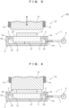
FIG. 3] FIG. 3 is a cross-sectional view of a pressurizing device equipped with the pressurizing suction-attachment table. - [
FIG. 4] FIG. 4 is a cross-sectional view showing a state where the object is pressurized by the pressurizing device. - [
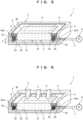
FIG. 5] FIG. 5 is a cross-sectional perspective view of a pressurizing suction-attachment table according toEmbodiment 2 of the present invention crossed in the center. - [
FIG. 6] FIG. 6 is a cross-sectional perspective view showing a state where an object placed on the pressurizing suction-attachment table is pressurized. - [
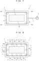
FIG. 7] FIG. 7 is a plan view showing an arrangement of springs in the pressurizing suction-attachment table. - [
FIG. 8] FIG. 8 is a plan view showing another arrangement of springs in the pressurizing suction-attachment table. - [
FIG. 9] FIG. 9 is a cross-sectional view of a pressurizing suction-attachment table according to another embodiment of the present invention. - Hereinafter, pressurizing suction-attachment tables and a pressurizing device equipped with the same according to
Embodiments Embodiments - As shown in
FIG. 1 , a pressurizing suction-attachment table 1 according to thepresent Embodiment 1 includes aporous body 2 having a suction-attachment surface 20 on which an object O can be placed, anelastic member 3 directly provided to thisporous body 2, and aframe body 5 supporting theporous body 2 via thiselastic member 3. Anaspiration space 4 is formed between theporous body 2 and theframe body 5. Additionally, the pressurizing suction-attachment table 1 includes anaspirator 6 capable of aspirating theaspiration space 4 to cause the object O to be suction-attached to the suction-attachment surface 20. Theporous body 2 includes anopposite surface 21 positioned on a side opposite to the suction-attachment surface 20. As shown inFIG. 2 , theframe body 5 includes a receivingsurface 51 for receiving theopposite surface 21 when theelastic member 3 is elastically deformed due to pressurization of the object O placed on the suction-attachment surface 20 toward the suction-attachment surface 20. The pressurizing suction-attachment table 1 is configured such that, when theopposite surface 21 is received by thereceiving surface 51, a reactive force from theporous body 2 to the object O that is being pressurized becomes uniform. - The
porous body 2 is not particularly limited as long as theporous body 2 includes the suction-attachment surface 20 and theopposite surface 21, forms theaspiration space 4 between theporous body 2 and theframe bodies 5, and applies the uniform reactive force to the object O when received by thereceiving surface 51 of theframe body 5 as shown inFIG. 1 . Additionally, theporous body 2 is made of a material (ceramics or the like) having a large number of holes. InEmbodiment 1 of the present invention (also inEmbodiment 2 described later), as a preferable mode, an example is shown in which theporous body 2 is a rectangular parallelepiped having the suction-attachment surface 20 and theopposite surface 21 as a top surface and a bottom surface, respectively, and having side surfaces 23. In this rectangular parallelepipedporous body 2, a part of the side surfaces 23 is attached to theelastic member 3, and the portions to which theelastic member 3 is not attached face theaspiration space 4. Additionally, in theporous body 2, theopposite surface 21 is flat and faces theaspiration space 4. Further, in theporous body 2, the suction-attachment surface 20 is arranged flush with theelastic member 3 and theframe body 5. Note that it is preferable that the surface roughness of the flatopposite surface 21 is 12.5 or less (Ra <= 12.5). - As a preferable
porous body 2 in a case where the object O is a powder material, each pore size is 50 µm or less (ϕ <= 50 µm), or the surface roughness of the suction-attachment surface 20 is 12.5 or less (Ra <= 12.5). This is because, with such a pore size or surface roughness, a surface of the powder material contacting the suction-attachment surface 20 will not be damaged even when the powder material (object O) slides and spreads due to the pressurization. Of course, it is more preferable to satisfy both the pore size and the surface roughness. Additionally, it is preferable that theporous body 2 contains carbon, and it is more preferable that theporous body 2 consists of carbon. This is because theporous body 2 accordingly functions as a cartridge at the time of electrostatic deposition of the powder material. The object O is not limited to the powder material alone, but may be a metallic foil or the like to which the powder material is suction-attached. Also in this case, since the surface roughness of the suction-attachment surface 20 is transferred to the powder material via the metallic foil by the pressurization, it is preferable that the surface roughness is 12.5 or less (Ra <= 12.5). - The
elastic member 3 is not particularly limited as long as theelastic member 3 is directly provided to theporous body 2, and is elastically deformed until theopposite surface 21 is received by the receivingsurface 51 due to the pressurization. InEmbodiment 1 of the present invention, as a preferable mode, an example is shown in which theelastic member 3 is a member integral with theframe body 5 and attached to theporous body 2. Here, an elastic coefficient E of theelastic member 3 is equal to or less than the value obtained by dividing a force F due to the pressurization (seeFIG. 2 ) by a distance d between theopposite surface 21 and the receiving surface 51 (seeFIG. 1 ) (E <= F/d). When such an elastic coefficient E, theelastic member 3 is elastically deformed until theopposite surface 21 is received by the receivingsurface 51 due to the pressurization. - The
frame body 5 is not particularly limited as long as theframe body 5 forms theaspiration space 4 between theframe body 5 and theporous bodies 2, and includes the receivingsurface 51 that receives theopposite surface 21 as shown inFIG. 1 . InEmbodiment 1 of the present invention (also inEmbodiment 2 described later), as a preferable mode, an example is shown in which theframe body 5 includes abottom plate 52 whose top surface serves as theflat receiving surface 51, andside plates 53 rising from outer edges of thisbottom plate 52. Theelastic member 3 is attached to upper portions of theseside plates 53. Theaspiration space 4 is a space enclosed by inner surfaces of theseside plates 53, the top surface (receiving surface 51) of thebottom plates 52, and theporous body 2. An aspiration opening 54 communicating with theaspiration space 4 is formed in one of theseside plates 53. Theaspirator 6 is connected to this aspiration opening 54 via apipe 7, a hose, or the like. Note that it is preferable that the surface roughness of theflat receiving surface 51 is 12.5 or less (Ra <= 12.5). - The
aspirator 6 is not particularly limited as long as theaspirator 6 can aspirate theaspiration space 4 to cause the object O to be suction-attached to the suction-attachment surface 20, but may be, for example, an exhaust pump. This exhaust pump has sufficient performance to cause the suction-attachment surface 20 to appropriately suction-attach the object O at the time of the pressurization. - Next, a
pressurizing device 100 equipped with the pressurizing suction-attachment table 1 will be described based onFIG. 3 and FIG. 4 . - As shown in
FIG. 3 and FIG. 4 , the pressurizingdevice 100 includes the pressurizing suction-attachment table 1, and a pressurizer 10 that pressurizes the object O placed on the suction-attachment surface 20 of the pressurizing suction-attachment table 1 toward the suction-attachment surface 20. - The
pressurizer 10 includes, for example, a fixed-type body 15 and a pressurizingpin 12 that moves in and out with respect to thisbody 15. In the pressurizingpin 12, a surface pressurizing the object O is parallel to the suction-attachment surface 20, and the direction in which the pressurizingpin 12 moves in and out is orthogonal to the suction-attachment surface 20. - Hereinafter, a description will be given of manufacturing methods of the pressurizing suction-attachment table 1 and the
pressurizing device 100 equipped with the same. - In the manufacture of the pressurizing suction-attachment table 1, as shown in
FIG. 3 , theporous body 2, theelastic member 3, and theframe body 5 are connected so that the suction-attachment surface 20 of theporous body 2, the top surface of theelastic member 3, and upper end surfaces of theside plates 53 of theframe body 5 are flush. On the other hand, theaspirator 6 is connected to the aspiration opening 54 formed in theside plate 53 of theframe body 5 via thepipe 7 or the like. In this manner, the pressurizing suction-attachment table 1 is manufactured. - In the manufacture of the
pressurizing device 100, as shown inFIG. 4 , thepressurizer 10 is arranged with respect to the pressurizing suction-attachment table 1 so that the pressurizingpin 12 projecting from thebody 15 of thepressurizer 10 is at a position for pressurizing the object O placed on theporous body 2. In this manner, the pressurizingdevice 100 is manufactured. - Hereinafter, a description will be given of a usage of the pressurizing suction-attachment table 1 and the
pressurizing device 100 equipped with the same. - As shown in
FIG. 3 , a user places the object O on the suction-attachment surface 20 of the pressurizing suction-attachment table 1, and on the other hand, causes theaspirator 6 to aspirate theaspiration space 4. Accordingly, theporous body 2 is widely aspirated from the side surfaces 23 and theopposite surface 21 facing thisaspiration space 4. Thus, aspiration is uniformly performed through each hole of the suction-attachment surface 20, and as a result, the object O is uniformly suction-attached to the suction-attachment surface 20. Further, since theporous body 2 is widely aspirated from the side surfaces 23 and theopposite surface 21, and thus sufficient aspiration is obtained through each hole of the suction-attachment surface 20, the object O is sufficiently suction-attached to the suction-attachment surface 20. Here, since theporous body 2 contains carbon, theporous body 2 functions as a cartridge at the time of electrostatic deposition of the powder material. Therefore, the powder material (object O) is uniformly deposited (placed), by electrostatic deposition, on a metallic foil (illustration omitted) placed on the suction-attachment surface 20 of theporous body 2. Thus, it is unnecessary to move a separately deposited powder material to the suction-attachment surface 20, and collapsing of the powder material due to such movement is prevented. - Then, as shown in
FIG. 4 , the user causes thepressurizer 10 to project the pressurizingpin 12 from thebody 15, so as to pressurize the object O toward the suction-attachment surface 20 by the pressurizingpin 12. With this pressurization, theelastic member 3 is elastically deformed, and theopposite surface 21 of theporous body 2 is received by the receivingsurface 51 of theframe body 5. At this time, a reactive force is generated from the receivingsurface 51 to the object O via theporous body 2. Here, since theopposite surface 21 of theporous body 2 and the receivingsurface 51 are both flat (preferably, the surface roughness is 12.5 or less), the reactive force generated from the receivingsurface 51 to the object O via theporous body 2 also becomes uniform. Note that since each pore size is 50 µm or less, and/or the surface roughness of the suction-attachment surface 20 is 12.5 or less, in a case where the object O is the powder material, even when the powder material (object O) slides and spreads on the suction-attachment surface 20 due to the pressurization, high accuracy is maintained without damaging a surface of the powder material contacting the suction-attachment surface 20. - In this manner, according to the pressurizing suction-attachment table 1 and the
pressurizing device 100 equipped with the same, since the object O is uniformly aspirated on the suction-attachment surface 20, and the reactive force from theporous body 2 to the object O that is being pressurized becomes uniform, the object O can be held in a state suitable for pressurization. - Additionally, since the
opposite surface 21 and the receivingsurface 51 are both flat (preferably, the surface roughness is 12.5 or less), and thus the reactive force is more uniformly maintained, the object O can be held in a state more suitable for pressurization. - Further, since the
elastic member 3 and theframe body 5 are integral, aspiration leakage does not occur between theelastic member 3 and theframe bodies 5. As a result, since the object O is more uniformly suction-attached to the suction-attachment surface 20, the object O can be held in a state more suitable for pressurization. - Additionally, since each pore size is 50 µm or less, and/or the surface roughness of the suction-
attachment surface 20 is 12.5 or less, in a case where the object O is the powder material, a surface of the powder material contacting the suction-attachment surface 20 will not be damaged, and thus it is possible to increase the accuracy of forming the object O by pressurization. - Additionally, since the
porous body 2 contains carbon, and theporous body 2 functions as a cartridge at the time of electrostatic deposition of the powder material on the metallic foil, it is unnecessary to move a separately deposited powder material (the object O) to the suction-attachment surface 20. As a result, collapsing of the powder material due to such movement is prevented, and the accuracy of forming the powder material (object O) by the pressurization can be increased. - Hereinafter, a pressurizing suction-attachment table 1 according to
Embodiment 2 will be described based onFIG. 5 to FIG. 8 . InEmbodiment 2, a description will be given focusing on theelastic member 3 and its vicinity, which have different configurations from those inEmbodiment 1, the same numerals are given to the same configurations as those inEmbodiment 1, and a description thereof will be omitted. Note that, for thepressurizing device 100, only the pressurizing suction-attachment table 1 equipped in thepressurizing device 100 differs betweenEmbodiment 1 and thepresent embodiment 2. Accordingly, hereinafter, a description of thepressurizing device 100 will be omitted. - As shown in
FIG. 5 and FIG. 6 , theframe body 5 of the pressurizing suction-attachment table 1 according to thepresent Embodiment 2 includes asupport member 8 attached to theporous body 2. As shown inFIG. 5 , thissupport member 8 is arranged to be flush with the suction-attachment surface 20 of theporous body 2. Theelastic members 3 of the pressurizing suction-attachment table 1 are springs 30 and/or rubber connecting thesupport member 8 and the receivingsurface 51 of theframe body 5. That is, the elastic members 3 (the springs 30 and/or rubber) of the pressurizing suction-attachment table 1 according to thepresent Embodiment 2 are provided to theporous body 2 indirectly (via the support member 8). Note that, inFIG. 5 to FIG. 8 and hereinafter, to simplify the description, theelastic members 3 will be described as the springs 30. - In
Embodiment 1, the member (elastic member 3) attached to theporous body 2 is bent due to pressurization. On the other hand, in thepresent embodiment 2, as shown inFIG. 6 , the member (support member 8) attached to theporous body 2 is not bent due to pressurization, but moves along with theporous body 2. Therefore, it is preferable to provide asealant 9, such as an O ring, which suppresses aspiration leakage, between theside plates 53 of theframe body 5 and thesupport member 8. - It is preferable that the arrangement of the springs 30 in plan view is such that the reactive force applied to the object O becomes uniform even before the
opposite surface 21 is received by the receivingsurface 51. Examples of this preferable arrangement are shown inFIG. 7 and FIG. 8 . As an example, as shown inFIG. 7 , it is preferable to arrange the springs 30 in the four corners of thesupport member 8 in plan view. As another example, as shown inFIG. 8 , it is preferable to arrange the adjacent springs 30 at equal intervals s in plan view. - In this manner, with the pressurizing suction-attachment table 1 and the
pressurizing device 100 equipped with the same according to thepresent Embodiment 2, the member (support member 8) attached to theporous body 2 is not bent due to pressurization, but moves along with theporous body 2. Therefore, the object O can be held in a state more suitable for pressurization. - Additionally, with the aforementioned preferable arrangement of the springs 30 (and/or rubber), the reactive force from the
porous body 2 to the object O that is being pressurized becomes uniform even before theopposite surface 21 is received by the receivingsurface 51. Therefore, the object O can be held in a state more suitable for pressurization. - Incidentally, although the plan view of the
frame body 5 and theporous body 2 has been described as a rectangle in the aforementioned Embodiments 1 and 2, it is not limited to this, and may be other shapes such as a circle. - Additionally, although it has been described in the aforementioned Embodiments 1 and 2 that the
opposite surface 21 and the receivingsurface 51 are both flat, and the aspiration opening 54 is formed in theside plate 53 of theframe body 5, it is not limited to this. For example, as shown inFIG. 9 ,protrusions 57 may be formed in the receivingsurface 51 of theframe body 5, and theopposite surface 21 may have a convex-concave shape that matches the receiving surface 51 (including the protrusions 57). In this case, in theporous body 2, the rigidity of portions 27 (portions having a small thickness) received by theprotrusions 57 is high, and the rigidity of portions 28 (portions having a large thickness) received by the receivingsurface 51 other than theprotrusions 57 is low, and when theopposite surface 21 of theporous body 2 is received by the receivingsurface 51, the resultant reactive force from the porous body 2 (27, 28) to the object O that is being pressurized should become uniform. Even when the rigidity of the portions 27 (portions having a small thickness) received by theprotrusions 57 is low, and the rigidity of the portions 28 (portions having a large thickness) received by the receivingsurface 51 other than theprotrusions 57 is high, when theopposite surface 21 of theporous body 2 is received by the receivingsurface 51, the resultant reactive force from the porous body 2 (27, 28) to the object O that is being pressurized should become uniform. Note thataspiration openings 54 may be formed in theprotrusions 57 or the like as shown inFIG. 9 , as long as the reactive force from theporous body 2 to the object O that is being pressurized becomes uniform. - Further, the aforementioned Embodiments 1 and 2 are illustrative in all respects, and not restrictive. The scope of the present invention is not indicated by the aforementioned description but by the claims, and it is intended to include all modifications within the meaning and scope of the claims and equivalents. Among the configurations described in the aforementioned embodiments and examples, the configurations other than the configuration set forth as the first invention in "Solution to Problem" are any configurations, and can be appropriately omitted or modified.
Claims (7)
- A pressurizing suction-attachment table, comprising:a porous body including a suction-attachment surface on which an object can be placed;an elastic member directly or indirectly provided to the porous body;a frame body that supports the porous body via the elastic member;an aspiration space formed between the porous body and the frame body; andan aspirator capable of aspirating the aspiration space to cause the object to be suction-attached to the suction-attachment surface,wherein the porous body includes an opposite surface positioned on a side opposite to the suction-attachment surface,the frame body includes a receiving surface for receiving the opposite surface when the elastic member is elastically deformed due to pressurization of the object placed on the suction-attachment surface onto the suction-attachment surface, andwhen the opposite surface is received by the receiving surface, a reactive force from the porous body to the object that is being pressurized becomes uniform.
- The pressurizing suction-attachment table according to claim 1,wherein each of the opposite surface of the porous body and the receiving surface of the frame body receiving the opposite surface is flat,the frame body includes an aspiration opening formed at a position other than the receiving surface and communicating with the aspiration space, andthe aspirator is connected to the aspiration opening.
- The pressurizing suction-attachment table according to claim 1 or 2, wherein the porous body includes side surfaces, and
the side surfaces and the opposite surface of the porous body face the aspiration space. - The pressurizing suction-attachment table according to claim 1 or 2, wherein the elastic member is a member integral with the frame body and attached to the porous body.
- The pressurizing suction-attachment table according to claim 1 or 2, wherein the frame body includes a support member attached to the porous body, and
the elastic member is a spring and/or rubber for connecting the support member and the receiving surface of the frame body. - The pressurizing suction-attachment table according to claim 1 or 2, wherein the porous body contains carbon.
- A pressurizing device, comprising:the pressurizing suction-attachment table according to claim 1 or 2; anda pressurizer that pressurizes the object placed on the suction-attachment surface of the pressurizing suction-attachment table toward the suction-attachment surface.
Applications Claiming Priority (2)
| Application Number | Priority Date | Filing Date | Title |
|---|---|---|---|
| JP2020105171A JP7330139B2 (en) | 2020-06-18 | 2020-06-18 | Adsorption table for pressurization and pressurization device equipped with the same |
| PCT/JP2021/021601 WO2021256317A1 (en) | 2020-06-18 | 2021-06-07 | Pressurizing suction-attachment table and pressurizing device equipped with same |
Publications (2)
| Publication Number | Publication Date |
|---|---|
| EP4170704A1 true EP4170704A1 (en) | 2023-04-26 |
| EP4170704A4 EP4170704A4 (en) | 2024-08-21 |
Family
ID=79196073
Family Applications (1)
| Application Number | Title | Priority Date | Filing Date |
|---|---|---|---|
| EP21824934.0A Pending EP4170704A4 (en) | 2020-06-18 | 2021-06-07 | PRESSURE SUCTION FIXING TABLE AND PRESSURIZATION DEVICE EQUIPPED WITH SAID FIXING TABLE |
Country Status (6)
| Country | Link |
|---|---|
| US (1) | US12318879B2 (en) |
| EP (1) | EP4170704A4 (en) |
| JP (1) | JP7330139B2 (en) |
| KR (1) | KR102794961B1 (en) |
| CN (1) | CN115699292B (en) |
| WO (1) | WO2021256317A1 (en) |
Family Cites Families (24)
| Publication number | Priority date | Publication date | Assignee | Title |
|---|---|---|---|---|
| JPH05344284A (en) | 1992-06-04 | 1993-12-24 | Asahi Optical Co Ltd | Image reader |
| JP2720331B2 (en) * | 1995-09-16 | 1998-03-04 | 日本ピラー工業株式会社 | Workpiece suction plate |
| JP3892703B2 (en) * | 2001-10-19 | 2007-03-14 | 富士通株式会社 | Semiconductor substrate jig and semiconductor device manufacturing method using the same |
| KR20040084128A (en) * | 2003-03-26 | 2004-10-06 | 한미반도체 주식회사 | Chuck table of Sawing equipment |
| JP2005205507A (en) * | 2004-01-20 | 2005-08-04 | Taiheiyo Cement Corp | Vacuum-sucking device and its manufacturing method |
| WO2006033498A1 (en) * | 2004-09-24 | 2006-03-30 | Hanmi Semiconductor Co., Ltd. | Chuck table for semiconductor manufacturing process |
| JP5261308B2 (en) * | 2009-07-24 | 2013-08-14 | リンテック株式会社 | Pressing device |
| JP5291687B2 (en) * | 2010-10-05 | 2013-09-18 | 三星ダイヤモンド工業株式会社 | Suction table |
| JP2012151418A (en) * | 2011-01-21 | 2012-08-09 | Topcon Corp | Suction stage |
| JP5772092B2 (en) * | 2011-03-11 | 2015-09-02 | 富士電機株式会社 | Semiconductor manufacturing method and semiconductor manufacturing apparatus |
| JP5766485B2 (en) * | 2011-03-31 | 2015-08-19 | 三菱重工業株式会社 | Vacuum suction support jig, plate workpiece processing method using the same, and workpiece |
| JP5831005B2 (en) * | 2011-07-25 | 2015-12-09 | セイコーエプソン株式会社 | Platen unit and liquid ejecting apparatus |
| JP5943742B2 (en) * | 2012-07-04 | 2016-07-05 | 三菱電機株式会社 | Semiconductor test jig and semiconductor test method using the same |
| JP5633766B2 (en) * | 2013-03-29 | 2014-12-03 | Toto株式会社 | Electrostatic chuck |
| JP6123459B2 (en) * | 2013-04-26 | 2017-05-10 | 日産自動車株式会社 | Manufacturing method of membrane electrode assembly |
| JP6627243B2 (en) * | 2015-04-02 | 2020-01-08 | 日本電気硝子株式会社 | Substrate processing method and substrate film forming method |
| US20170053822A1 (en) * | 2015-08-23 | 2017-02-23 | Camtek Ltd. | Warped wafers vacuum chuck |
| CN205542736U (en) * | 2016-02-03 | 2016-08-31 | 宸榤精机股份有限公司 | Adsorption-type jig for wafer dicing with high adsorption properties |
| JP6842948B2 (en) * | 2017-02-24 | 2021-03-17 | リンテック株式会社 | Positioning device and positioning method |
| JP6881284B2 (en) * | 2017-12-27 | 2021-06-02 | 株式会社Sumco | Suction chuck |
| JP2019166597A (en) * | 2018-03-23 | 2019-10-03 | 株式会社ナノテム | Elastic deformable pad, suction pad unit, vacuum chuck device and machine tool |
| JP7002014B2 (en) * | 2018-10-30 | 2022-01-20 | Toto株式会社 | Electrostatic chuck |
| KR102607586B1 (en) * | 2018-11-05 | 2023-11-30 | 삼성디스플레이 주식회사 | Substrate supportiong device and method of polishing substrate using the same |
| JP7172459B2 (en) | 2018-11-06 | 2022-11-16 | コニカミノルタ株式会社 | Recording medium conveying device and image recording device |
-
2020
- 2020-06-18 JP JP2020105171A patent/JP7330139B2/en active Active
-
2021
- 2021-06-07 KR KR1020227040108A patent/KR102794961B1/en active Active
- 2021-06-07 CN CN202180039945.2A patent/CN115699292B/en active Active
- 2021-06-07 WO PCT/JP2021/021601 patent/WO2021256317A1/en not_active Ceased
- 2021-06-07 US US17/927,615 patent/US12318879B2/en active Active
- 2021-06-07 EP EP21824934.0A patent/EP4170704A4/en active Pending
Also Published As
| Publication number | Publication date |
|---|---|
| KR20230028229A (en) | 2023-02-28 |
| EP4170704A4 (en) | 2024-08-21 |
| JP7330139B2 (en) | 2023-08-21 |
| KR102794961B1 (en) | 2025-04-10 |
| CN115699292A (en) | 2023-02-03 |
| US20230166370A1 (en) | 2023-06-01 |
| US12318879B2 (en) | 2025-06-03 |
| JP2021197527A (en) | 2021-12-27 |
| WO2021256317A1 (en) | 2021-12-23 |
| CN115699292B (en) | 2026-04-28 |
Similar Documents
| Publication | Publication Date | Title |
|---|---|---|
| EP3605597B1 (en) | Silicon chip holding device, silicon chip conveying device, silicon chip delivery system and conveying method | |
| TWI309993B (en) | ||
| JP4724562B2 (en) | Vacuum suction head, vacuum suction device and table using the vacuum suction head | |
| EP0456426A1 (en) | Vacuum type wafer holder | |
| JPH0312948A (en) | Substrate holder | |
| JPH07136885A (en) | Vacuum chuck | |
| US9054140B2 (en) | Substrate holder system, substrate holder, fastening mechanism, substrate bonding apparatus and method for manufacturing devices | |
| US12318879B2 (en) | Pressurizing suction-attachment table and pressurizing device equipped with the same | |
| CN113968065B (en) | Laminating device and curved surface laminating jig | |
| US20250205907A1 (en) | Lifting head and lifting device | |
| CN105364634A (en) | Profiling apparatus | |
| JP2750554B2 (en) | Vacuum suction device | |
| JP3769618B2 (en) | Vacuum adsorption device | |
| JP3817613B2 (en) | Vacuum adsorption device | |
| JP4863350B2 (en) | Adhesive sheet and holding jig | |
| CN216389308U (en) | Wafer adsorption device constructs and weighing device | |
| JPH09280852A (en) | Holder for thin plate, method and device for measuring thickness of thin plate | |
| JPH09225768A (en) | Substrate holding device | |
| CN114724997A (en) | Suction device of chip cover body, chip mounter, and related system, method and application | |
| WO2019018786A1 (en) | Non-contact handler and method of handling workpieces using the same | |
| JP2025112971A (en) | Coating Equipment | |
| JP2000153455A (en) | Vacuum chucking head | |
| JPS6228759Y2 (en) | ||
| TW202204163A (en) | Attaching device and complex curved-surface attaching intermediary | |
| JPS5914437A (en) | Vacuum chuck |
Legal Events
| Date | Code | Title | Description |
|---|---|---|---|
| STAA | Information on the status of an ep patent application or granted ep patent |
Free format text: STATUS: THE INTERNATIONAL PUBLICATION HAS BEEN MADE |
|
| PUAI | Public reference made under article 153(3) epc to a published international application that has entered the european phase |
Free format text: ORIGINAL CODE: 0009012 |
|
| STAA | Information on the status of an ep patent application or granted ep patent |
Free format text: STATUS: REQUEST FOR EXAMINATION WAS MADE |
|
| 17P | Request for examination filed |
Effective date: 20221201 |
|
| AK | Designated contracting states |
Kind code of ref document: A1 Designated state(s): AL AT BE BG CH CY CZ DE DK EE ES FI FR GB GR HR HU IE IS IT LI LT LU LV MC MK MT NL NO PL PT RO RS SE SI SK SM TR |
|
| DAV | Request for validation of the european patent (deleted) | ||
| DAX | Request for extension of the european patent (deleted) | ||
| A4 | Supplementary search report drawn up and despatched |
Effective date: 20240718 |
|
| RIC1 | Information provided on ipc code assigned before grant |
Ipc: H01L 21/683 20060101AFI20240712BHEP |
|
| RAP3 | Party data changed (applicant data changed or rights of an application transferred) |
Owner name: KANADEVIA CORPORATION |