EP4170367B1 - Vorrichtung und verfahren zur schätzung der batteriekapazität - Google Patents
Vorrichtung und verfahren zur schätzung der batteriekapazität Download PDFInfo
- Publication number
- EP4170367B1 EP4170367B1 EP21856159.5A EP21856159A EP4170367B1 EP 4170367 B1 EP4170367 B1 EP 4170367B1 EP 21856159 A EP21856159 A EP 21856159A EP 4170367 B1 EP4170367 B1 EP 4170367B1
- Authority
- EP
- European Patent Office
- Prior art keywords
- data
- voltage
- battery
- capacity estimation
- battery cell
- Prior art date
- Legal status (The legal status is an assumption and is not a legal conclusion. Google has not performed a legal analysis and makes no representation as to the accuracy of the status listed.)
- Active
Links
Images


Classifications
-
- G—PHYSICS
- G01—MEASURING; TESTING
- G01R—MEASURING ELECTRIC VARIABLES; MEASURING MAGNETIC VARIABLES
- G01R31/00—Arrangements for testing electric properties; Arrangements for locating electric faults; Arrangements for electrical testing characterised by what is being tested not provided for elsewhere
- G01R31/36—Arrangements for testing, measuring or monitoring the electrical condition of accumulators or electric batteries, e.g. capacity or state of charge [SoC]
- G01R31/392—Determining battery ageing or deterioration, e.g. state of health
-
- G—PHYSICS
- G01—MEASURING; TESTING
- G01R—MEASURING ELECTRIC VARIABLES; MEASURING MAGNETIC VARIABLES
- G01R31/00—Arrangements for testing electric properties; Arrangements for locating electric faults; Arrangements for electrical testing characterised by what is being tested not provided for elsewhere
- G01R31/36—Arrangements for testing, measuring or monitoring the electrical condition of accumulators or electric batteries, e.g. capacity or state of charge [SoC]
- G01R31/3644—Constructional arrangements
- G01R31/3648—Constructional arrangements comprising digital calculation means, e.g. for performing an algorithm
-
- G—PHYSICS
- G01—MEASURING; TESTING
- G01R—MEASURING ELECTRIC VARIABLES; MEASURING MAGNETIC VARIABLES
- G01R31/00—Arrangements for testing electric properties; Arrangements for locating electric faults; Arrangements for electrical testing characterised by what is being tested not provided for elsewhere
- G01R31/36—Arrangements for testing, measuring or monitoring the electrical condition of accumulators or electric batteries, e.g. capacity or state of charge [SoC]
- G01R31/367—Software therefor, e.g. for battery testing using modelling or look-up tables
-
- G—PHYSICS
- G01—MEASURING; TESTING
- G01R—MEASURING ELECTRIC VARIABLES; MEASURING MAGNETIC VARIABLES
- G01R31/00—Arrangements for testing electric properties; Arrangements for locating electric faults; Arrangements for electrical testing characterised by what is being tested not provided for elsewhere
- G01R31/36—Arrangements for testing, measuring or monitoring the electrical condition of accumulators or electric batteries, e.g. capacity or state of charge [SoC]
- G01R31/382—Arrangements for monitoring battery or accumulator variables, e.g. SoC
- G01R31/3835—Arrangements for monitoring battery or accumulator variables, e.g. SoC involving only voltage measurements
-
- G—PHYSICS
- G01—MEASURING; TESTING
- G01R—MEASURING ELECTRIC VARIABLES; MEASURING MAGNETIC VARIABLES
- G01R31/00—Arrangements for testing electric properties; Arrangements for locating electric faults; Arrangements for electrical testing characterised by what is being tested not provided for elsewhere
- G01R31/36—Arrangements for testing, measuring or monitoring the electrical condition of accumulators or electric batteries, e.g. capacity or state of charge [SoC]
- G01R31/385—Arrangements for measuring battery or accumulator variables
- G01R31/387—Determining ampere-hour charge capacity or SoC
- G01R31/388—Determining ampere-hour charge capacity or SoC involving voltage measurements
-
- G—PHYSICS
- G01—MEASURING; TESTING
- G01R—MEASURING ELECTRIC VARIABLES; MEASURING MAGNETIC VARIABLES
- G01R31/00—Arrangements for testing electric properties; Arrangements for locating electric faults; Arrangements for electrical testing characterised by what is being tested not provided for elsewhere
- G01R31/36—Arrangements for testing, measuring or monitoring the electrical condition of accumulators or electric batteries, e.g. capacity or state of charge [SoC]
- G01R31/396—Acquisition or processing of data for testing or for monitoring individual cells or groups of cells within a battery
-
- H—ELECTRICITY
- H01—ELECTRIC ELEMENTS
- H01M—PROCESSES OR MEANS, e.g. BATTERIES, FOR THE DIRECT CONVERSION OF CHEMICAL ENERGY INTO ELECTRICAL ENERGY
- H01M10/00—Secondary cells; Manufacture thereof
- H01M10/42—Methods or arrangements for servicing or maintenance of secondary cells or secondary half-cells
- H01M10/48—Accumulators combined with arrangements for measuring, testing or indicating the condition of cells, e.g. the level or density of the electrolyte
-
- Y—GENERAL TAGGING OF NEW TECHNOLOGICAL DEVELOPMENTS; GENERAL TAGGING OF CROSS-SECTIONAL TECHNOLOGIES SPANNING OVER SEVERAL SECTIONS OF THE IPC; TECHNICAL SUBJECTS COVERED BY FORMER USPC CROSS-REFERENCE ART COLLECTIONS [XRACs] AND DIGESTS
- Y02—TECHNOLOGIES OR APPLICATIONS FOR MITIGATION OR ADAPTATION AGAINST CLIMATE CHANGE
- Y02E—REDUCTION OF GREENHOUSE GAS [GHG] EMISSIONS, RELATED TO ENERGY GENERATION, TRANSMISSION OR DISTRIBUTION
- Y02E60/00—Enabling technologies; Technologies with a potential or indirect contribution to GHG emissions mitigation
- Y02E60/10—Energy storage using batteries
Definitions
- the present invention relates to an apparatus and method for estimating a capacity of a battery by configuring a model separately for data that is easy to analyze and data that is not easy to analyze.
- the secondary batteries which are chargeable/dischargeable batteries, may include all of conventional nickel (Ni)/cadmium (Cd) batteries, Ni/metal hydride (MH) batteries, etc., and recent lithium ion batteries.
- a lithium ion battery has a much higher energy density than those of the conventional Ni/Cd batteries, Ni/MH batteries, etc.
- the lithium ion battery may be manufactured to be small and lightweight, such that the lithium ion battery has been used as a power source of mobile devices.
- the lithium ion battery is attracting attention as a next-generation energy storage medium as a usage range thereof is expanded to a power source of electric vehicles.
- the secondary battery is generally used as a battery pack including a battery module where a plurality of battery cells are connected to one another in series and/or in parallel.
- the battery pack may be managed and controlled by a battery management system in terms of a state and an operation.
- Such a secondary battery is subject to a lot assembly test (LAT) in a production process to determine a quality of each cell in production.
- LAT lot assembly test
- one sample may be selected for each lot, which is a unit of a plurality of cells, to perform the LAT.
- the LAT is intended to check if a capacity of the secondary battery is greater than or equal to a specific level even after 300 cycles through accelerated degradation of the secondary battery.
- data logged in the LAT may include data that is easy to analyze and data that is not easy to analyze, together, such that there may be a difficulty in analysis of a data value and accuracy may be degraded.
- Prior art document US2016/0195587 discloses an arrangement for estimating battery capacity based on voltage/current measurements, involving dividing up measured data into time segments and applying a model thereto.
- the present invention has been made to solve the foregoing problems, and aims to provide a battery capacity estimation apparatus and method in which data that is easy to analyze and data that is not easy to analyze are distinguished from among logging data of a battery cell and a capacity estimation model is applied to each data, thereby accurately and efficiently estimating a capacity of the battery cell.
- a battery capacity estimation apparatus includes a voltage measuring unit configured to measure a voltage of a battery cell, a filtering unit configured to determine voltage data as first data when a logging pattern of the voltage data of the battery cell deviates from a preset reference range, a statistical analyzing unit configured to determine second data through statistical analysis on the voltage data of the battery cell, and a capacity estimating unit configured to estimate a capacity by applying data, classified by the filtering unit or the statistical analyzing unit for a battery cell that is a measurement target, to capacity estimation models generated separately for the first data and the second data.
- a battery capacity estimation method includes measuring a voltage of a battery cell, determining voltage data as first data when a logging pattern of the voltage data of the battery cell deviates from a preset reference range, determining second data through statistical analysis on the voltage data of the battery cell, and estimating a capacity of the battery cell by applying the first data and the second data to capacity estimation models, respectively.
- data that is easy to analyze and data that is not easy to analyze may be distinguished from among logging data of a battery cell and a capacity estimation model may be applied to each data, thereby accurately and efficiently estimating a capacity of the battery cell.
- first, second, or the like may modify various components regardless of order and/or importance, and do not limit the components.
- a first component may be named as a second component without departing from the right scope of the present disclosure, and similarly, the second component may be named as the first component.
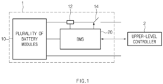
- FIG. 1 is a block diagram of a general battery rack.
- FIG. 1 a battery control system including a battery rack 1 and a upper-level controller 2 included in a upper-level system according to an embodiment of the present invention is schematically shown.
- the battery rack 1 may include a battery module 10 that includes one or more battery cells and is chargeable/dischargeable, a switching unit 14 serially connected to a positive (+) terminal side or a negative (-) terminal side of the battery module 10 to control a charging/discharging current flow of the battery module 10, and a battery management system (e.g., RBMS) 20 for control and management to prevent over-charging and over-discharging by monitoring a voltage, a current, a temperature, etc., of the battery rack 1.
- the battery rack 1 may include a plurality of battery modules 10, sensors 12, switching units 14, and battery management systems 20.
- the switching unit 14 which is an element for controlling a current flow for charging or discharging of the plurality of battery modules 10, for example, at least one relay, magnetic contactor, etc., may be used according to specifications of the battery rack 1.
- the battery management system 20 which is an interface for receiving measurement values of the above-described various parameters, may include a plurality of terminals and a circuit, etc., connected thereto to process input values.
- the battery management system 20 may control on/off of the switching unit 14, e.g., a relay, a contactor, etc., and may be connected to the battery module 10 to monitor the state of each battery module 10.
- the battery management system 20 may perform regression analysis on a voltage of a battery cell through a separate program, as will be described below.
- An abnormal type of the battery cell may be classified using a calculated regression equation.
- the upper-level controller 2 may transmit a control signal for the battery module 10 to the battery management system 20.
- the battery management system 20 may also be controlled in terms of an operation thereof based on a signal applied from the upper-level controller 2.
- the battery cell according to the present invention may be included in the battery module 10 used for an energy storage system (ESS).
- the upper-level controller 2 may be a controller (BBMS) of a battery bank including a plurality of racks or an ESS controller for controlling the entire ESS including a plurality of banks.
- the battery rack 1 is not limited to such a purpose.
- Such configurations of the battery rack 1 and the battery management system 20 are well-known configurations, and thus will not be described in detail.
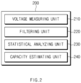
- FIG. 2 is a block diagram showing a structure of a battery capacity estimation apparatus according to an embodiment of the present invention.
- a battery capacity estimation apparatus 200 may include a voltage measuring unit 210, a filtering unit 220, a static analyzing unit 230, and a capacity estimating unit 240.
- the battery capacity estimation apparatus 200 may estimate a capacity of the battery cell by analyzing charging and discharging data of the battery in real time, or may perform a test by sampling a failure before mounting in a module in manufacturing of the battery cell.
- the voltage measuring unit 210 may measure a voltage of the battery cell. In this case, the voltage measuring unit 210 may measure the voltage of the battery cell at specific time intervals. For example, the voltage measuring unit 210 may measure a voltage for a rest period after charging or discharging of the battery cell. In addition, the voltage measuring unit 210 may measure current flowing in the battery cell.
- the filtering unit 220 may determine the voltage data as first data. More specifically, when at least one of a logging time and the number of voltage data of the battery cell deviates from a reference range, the filtering unit 220 may determine the voltage data as the first data.
- the logging pattern of the voltage data of the battery cell may be intended to extract four voltage data in the unit of 5 minutes.
- the filtering unit 220 may classify corresponding data as the first data.
- the statistical analyzing unit 230 may determine second data through statistical analysis on the voltage data of the battery cell. In this case, the statistical analyzing unit 230 may perform statistical analysis on data other than data determined as the first data by the filtering unit 220.
- the statistical analyzing unit 230 may calculate differential data dV/dt, for the battery cell, of a voltage with respect to a time. As will be described below, the differential data of the voltage with respect to the time shows more prominent tendency than logged voltage data, such that the statistical analyzing unit 230 may use the differential data of the voltage with respect to the time.
- the statistical analyzing unit 230 may extract principal component data for voltage data by performing principal component analysis (PCA) on the differential data.
- PCA principal component analysis
- the statistical analyzing unit 230 may calculate a plurality of clusters through k-means clustering on the principal component data, and determine differential data included in a particular cluster as second data and differential data not included in the cluster as the first data.
- the first data may be data in which the voltage data of the battery cell is in a discontinuous form
- the second data may be data in which the voltage data of the battery cell is in a continuous form. That is, the first data may be data that is not be easy to analyze and the second data may be data that is easy to analyze.
- the battery capacity estimation apparatus 200 may apply a capacity estimation model separately for the first data and the second data which have different general shapes, thereby improving accuracy in comparison to when data where the first data and the second data are combined is used conventionally.
- accuracy may be improved by separately applying data to the capacity estimation model.
- the capacity estimation unit 240 may estimate a capacity by applying data, classified by the filtering unit 220 or the statistical analyzing unit 230 for the battery cell that is a measurement target, to the capacity estimation model generated separately for the first data and the second data.
- the capacity estimation model may be a long short-term memory networks (LSTM) model.
- the capacity estimation model generated for each of the first data and the second data may include a different parameter value.
- the battery capacity estimation apparatus 200 may include a storing unit.
- the storing unit may store various data such as voltage data measured by the voltage measuring unit 210, voltage data classified by the filtering unit 220 and the statistical analyzing unit 230, a capacity estimation program, etc.
- the battery capacity estimation apparatus 200 according to an embodiment of the present invention may operate by transmitting and receiving the above-described data in communication with an external server through a communicating unit (not shown), instead of including the storing unit.
- data that is easy to analyze and data that is not easy to analyze may be distinguished from among logging data of a battery cell and a capacity estimation model may be applied to each data, thereby accurately and efficiently estimating a capacity of the battery cell.
- FIG. 3 is a flowchart showing an operation, performed by a battery capacity estimation apparatus, of classifying data according to an embodiment of the present invention.
- the logging scheme may be logging four voltage data at an interval of 5 minutes.
- the voltage data When the voltage data is out of the preset logging scheme (NO), the voltage data may be classified as the first data in operation S330. On the other hand, when the voltage data is logged normally according to the preset scheme (YES), differential data dV/dt of the voltage data with respect to a time may be calculated in operation S340.
- feature (principal component) data may be extracted through PCA with respect to the differential data of the voltage.
- a dimension of data may be reduced.
- the data By applying k-mean clustering to the principal component data, the data may be classified into a plurality of clusters in operation S360.
- the data When the classified data is not included in a particular cluster (e.g., Cluster 2) (NO), the data may be classified as the first data in operation S370. On the other hand, when the data is included in the particular cluster (YES), the data may be classified as second data in operation S380.
- a particular cluster e.g., Cluster 2
- the data may be classified as the first data in operation S370.
- the data when the data is included in the particular cluster (YES), the data may be classified as second data in operation S380.
- voltage data may be identified by checking a time unit of logging data and using PCA and a k-mean clustering algorithm.
- data having similar features may be classified, thereby efficiently and accurately performing battery capacity estimation.
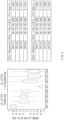
- FIG. 4 is a diagram showing a correlation between logging data and a capacity of a battery cell.
- a left graph may indicate a correlation with a battery capacity (e.g., a SOH) (a y axis) with respect to each of differential data (dV1, dV2, dV3, and dV4) (an x axis) of a voltage with respect to a time after charging and discharging
- a right table may indicate logging data of a voltage after charging and discharging of the battery.
- the x axis may indicate voltage differential data dV1, dV2, dV3, and dV4 after charging and voltage differential data dV1, dV2, dV3, and dV4 after discharging.
- a correlation with a battery capacity may be high as a y-axis value is close to 1 or -1 and a length of a vertical bar is short. That is, it may be seen that data (25 and 29) immediately after charging and discharging has a higher correlation with a battery capacity value than other data. This is because a voltage change immediately after charging and discharging is more distinct than a voltage change thereafter.
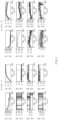
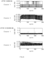
- FIG. 5 is a diagram showing that logging data of a battery cell is classified into a plurality of clusters by a battery capacity estimation apparatus according to an embodiment of the present invention.
- an x axis may indicate the number of charging and discharging cycles of a battery cell and a y axis may indicate differential data dV1 through dV4 of a voltage with respect to a time in a rest period after charging and discharging of the battery cell.
- Cluster 1 may indicate the above-described first data and
- Cluster 2 may indicate the above-described second data.
- the first data belonging to Cluster 1 may indicate that data is relatively discontinuous. That is, the first data may be irregular by nature, and thus may not be easy to perform battery capacity analysis thereon.
- the second data belonging to Cluster 2 may be continuous and have a gentle curve when compared to the first data. That is, the second data may have more constant tendency than the first data and may be easy to analyze.
- FIG. 6 is a diagram showing that logging data of all battery cells are classified into a plurality of clusters by a battery capacity estimation apparatus according to an embodiment of the present invention.
- an x axis may indicate the number of charging and discharging cycles of a battery cell
- a y axis may indicate differential data dV2 of a voltage with respect to a time in a rest period after charging and discharging of the entire battery cell.
- FIG. 7 shows an example of an LSTM of a battery capacity estimation apparatus according to an embodiment of the present invention.
- the capacity estimation model shown in FIG. 7 may indicate an LSTM.
- C may indicate long-term information
- h may indicate information in a previous step
- ⁇ and tanh may indicate activation functions
- W may indicate a weight value
- b may indicate noise.
- the LSTM of FIG. 7 may include a forget gate layer, a decision layer, a new state value updating operation, and an output value deciding operation.
- the forget gate layer may determine whether to retain (1) or discard (0) certain information with an input of ht-1 and Xt having an output value between 0 and 1.
- a value to be updated for storing a new state may be determined.
- a value to be updated may be determined in the input gate layer, and a vector C of new candidate values to be newly added to a cell state may be generated in the tanh layer.
- an old cell state Ct-1 may be updated into a new cell state Ct.
- a value to be output may be determined and a value between -1 and 1 for a cell state may be extracted through a tanh function, after which an output value may be multiplied by the output value of the forget gate layer.
- a capacity value (e.g., a capacity %) of the battery cell may be output through the foregoing processes.
- the LSTM model of FIG. 7 has a known configuration and thus will not be described in detail.
- the LSTM of FIG. 7 is merely an example, such that the capacity estimation model according to the present invention is not limited thereto and various estimation models may be used.
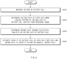
- FIG. 8 is a flowchart showing a battery capacity estimation method according to an embodiment of the present invention.
- a battery capacity estimation method measures a voltage of a battery cell in operation S810.
- the voltage of the battery cell may be measured at specific time intervals. For example, a voltage may be measured for a rest period after charging or discharging of the battery cell.
- the voltage data When a logging pattern of voltage data of the battery cell deviates from a preset reference range, the voltage data may be determined as the first data, in operation S820. More specifically, when at least one of a logging time and the number of voltage data of the battery cell deviates from the reference range, the voltage data may be determined as the first data. For example, the logging pattern of the voltage data of the battery cell may be intended to extract four voltage data in the unit of 5 minutes.
- second data may be determined through statistical analysis on the voltage data of the battery cell, in operation S830.
- Differential data dV/dt, for the battery cell, of a voltage with respect to a time may be calculated in operation S830.
- principal component data for voltage data may be extracted by performing PCA on the differential data, in operation S830.
- a plurality of clusters may be calculated through k-means clustering on the principal component data, and differential data included in a particular cluster may be determined as the second data and differential data not included in the cluster as the first data.
- the first data and the second data extracted in operations S820 and S830 may be applied to the capacity estimation model, respectively, thereby estimating the capacity of the battery cell in operation S840.
- the capacity estimation model may be an LSTM model.
- the capacity estimation models of the first data and the second data may be identical, but parameter values input to the capacity estimation models may be different.
- data that is easy to analyze and data that is not easy to analyze may be distinguished from among logging data of a battery cell and a capacity estimation model may be applied to each data, thereby accurately and efficiently estimating a capacity of the battery cell.
- FIG. 9 is a block diagram showing a hardware structure of a battery abnormality diagnosis apparatus according to an embodiment of the present invention.
- a battery capacity estimation apparatus 900 may include a microcontroller unit (MCU) 910, a memory 920, an input/output interface (I/F) 930, and a communication I/F 940.
- MCU microcontroller unit
- I/F input/output interface
- the MCU 910 may be a processor that executes various programs (e.g., a battery capacity estimation program, a principal component analysis program, a k-means clustering program, etc.) stored in the memory 920, processes various data for data classification, capacity estimation, etc., of the battery cell through these programs, and executes the above-described functions of FIG. 2 .
- programs e.g., a battery capacity estimation program, a principal component analysis program, a k-means clustering program, etc.
- the memory 920 may store various programs regarding statistical analysis, capacity estimation, etc., of the battery cell. Moreover, the memory 920 may store various data such as voltage data of the battery cell, differential data of a voltage of the battery cell, etc.
- the memory 920 may be provided in plural, depending on a need.
- the memory 920 may be a volatile or nonvolatile memory.
- RAM random access memory
- DRAM dynamic RAM
- SRAM static RAM
- ROM read only memory
- PROM programmable ROM
- EAROM electrically alterable ROM
- EPROM erasable PROM
- EEPROM electrically erasable PROM
- flash memory etc.
- the above-listed examples of the memory 720 are merely examples and are not limited thereto.
- the input/output I/F 930 may provide an interface for transmitting and receiving data by connecting an input device (not shown) such as a keyboard, a mouse, a touch panel, etc., and an output device such as a display (not shown), etc., with the MCU 710.
- an input device such as a keyboard, a mouse, a touch panel, etc.
- an output device such as a display (not shown), etc.
- the communication I/F 940 which is a component capable of transmitting and receiving various data to and from a server, may be various types of devices capable of supporting wired or wireless communication.
- a program for statistical analysis and capacity estimation or various data may be transmitted and received to and from a separately provided external server through the communication I/F 940.
- a computer program according to an embodiment of the present invention may be recorded in the memory 920 and processed by the MCU 910, thus being implemented as a module that performs function blocks shown in FIG. 2 .
Landscapes
- Physics & Mathematics (AREA)
- General Physics & Mathematics (AREA)
- Engineering & Computer Science (AREA)
- Manufacturing & Machinery (AREA)
- Chemical & Material Sciences (AREA)
- Chemical Kinetics & Catalysis (AREA)
- Electrochemistry (AREA)
- General Chemical & Material Sciences (AREA)
- Secondary Cells (AREA)
- Charge And Discharge Circuits For Batteries Or The Like (AREA)
- Tests Of Electric Status Of Batteries (AREA)
Claims (15)
- Batteriekapazität-Schätzvorrichtung, umfassend:eine Spannung-Messeinheit (210), welche dazu eingerichtet ist, eine Spannung einer Batteriezelle zu messen;eine Filtereinheit (220), welche dazu eingerichtet ist, Spannungsdaten als erste Daten zu bestimmen, wenn ein Erfassungsmuster der Spannungsdaten der Batteriezelle von einem vorbestimmten Referenzbereich abweicht;eine statistische Analyseeinheit (230), welche dazu eingerichtet ist, zweite Daten durch statistische Analyse auf die Spannungsdaten der Batteriezelle zu bestimmen; undeine Kapazität-Schätzeinheit (240), welche dazu eingerichtet ist, eine Kapazität durch Anwenden von Daten, welche durch die Filtereinheit oder die statistische Analyseeinheit für eine Batteriezelle klassifiziert werden, welche ein Messungsziel ist, auf Kapazität-Schätzmodelle zu schätzen, welche separat für die ersten Daten und die zweiten Daten erzeugt werden.
- Batteriekapazität-Schätzvorrichtung nach Anspruch 1, wobei die statistische Analyseeinheit dazu eingerichtet ist, eine statistische Analyse auf andere Daten als Daten anzuwenden, welche als die ersten Daten von der Filtereinheit bestimmt werden.
- Batteriekapazität-Schätzvorrichtung nach Anspruch 1, wobei die statistische Analyseeinheit dazu eingerichtet ist, differentielle Daten einer Spannung der Batteriezelle bezüglich einer Zeit zu berechnen.
- Batteriekapazität-Schätzvorrichtung nach Anspruch 3, wobei die statistische Analyseeinheit dazu eingerichtet ist, eine Mehrzahl von differentiellen Daten als prinzipielle Komponentendaten durch Durchführen einer prinzipiellen Komponenten-Analyse (PCA) auf die Mehrzahl von differentiellen Daten zu extrahieren.
- Batteriekapazität-Schätzvorrichtung nach Anspruch 4, wobei die statistische Analyseeinheit dazu eingerichtet ist, eine Mehrzahl von Clustern durch k-Means-Clustern auf die prinzipiellen Komponentendaten zu berechnen, und die differentiellen Daten als die zweiten Daten bestimmt, wenn die differentiellen Daten in einem vorbestimmten Cluster umfasst sind.
- Batteriekapazität-Schätzvorrichtung nach Anspruch 5, wobei die statistische Analyseeinheit dazu eingerichtet ist, differentielle Daten, welche nicht in dem Cluster umfasst sind, als die ersten Daten zu bestimmen.
- Batteriekapazität-Schätzvorrichtung nach Anspruch 1, wobei das Kapazität-Schätzmodell ein langes Kurzzeitgedächtnis-Netzwerke (LSTM)- Modell ist.
- Batteriekapazität-Schätzvorrichtung nach Anspruch 1, wobei die Spannung-Messeinheit dazu eingerichtet ist, eine Spannung für eine Ruheperiode nach einem Laden oder Entladen der Batteriezelle zu messen.
- Batteriekapazität-Schätzvorrichtung nach Anspruch 1, wobei wenn wenigstens eines aus einer Erfassungszeit und einer Anzahl von Spannungsdaten der Batteriezelle von dem Referenzbereich abweicht, die Filtereinheit die Spannungsdaten als die ersten Daten bestimmt.
- Batteriekapazität-Schätzvorrichtung nach Anspruch 1, wobei die ersten Daten Daten sind, in welchen die Spannungsdaten der Batteriezelle in einer diskontinuierlichen Form vorliegen, und die zweiten Daten Daten sind, in welchen die Spannungsdaten der Batteriezelle in einer kontinuierlichen Form vorliegen.
- Batteriekapazität-Schätzverfahren, umfassend:Messen (S810) einer Spannung einer Batteriezelle;Bestimmen (S820) von Spannungsdaten als erste Daten, wenn ein Erfassungsmuster der Spannungsdaten der Batteriezelle von einem vorbestimmten Referenzbereich abweicht;Bestimmen (S830) von zweiten Daten durch statistische Analyse auf die Spannungsdaten der Batteriezelle; undSchätzen (S840) einer Kapazität der Batteriezelle durch jeweiliges Anwenden der ersten Daten und der zweiten Daten auf Kapazität-Schätzmodelle.
- Batteriekapazität-Schätzverfahren nach Anspruch 11, ferner umfassend ein Berechnen von differentiellen Daten einer Spannung bezüglich einer Zeit für die Batteriezelle.
- Batteriekapazität-Schätzverfahren nach Anspruch 12, ferner umfassend ein Extrahieren einer Mehrzahl von differentiellen Daten als prinzipielle Komponentendaten durch Durchführen einer prinzipiellen Komponentenanalyse (PCA) auf die Mehrzahl von differentiellen Daten.
- Batteriekapazität-Schätzverfahren nach Anspruch 13, wobei das Bestimmen der zweiten Daten ein Berechnen einer Mehrzahl von Clustern durch k-Means-Clustern auf die prinzipiellen Komponentendaten und Bestimmen der differentiellen Daten als die zweiten Daten umfasst, wenn die differentiellen Daten in einem vorbestimmten Cluster umfasst sind.
- Batteriekapazität-Schätzverfahren nach Anspruch 14, ferner umfassend ein Bestimmen von differentiellen Daten, welche nicht in dem Cluster umfasst sind, als die ersten Daten.
Applications Claiming Priority (2)
| Application Number | Priority Date | Filing Date | Title |
|---|---|---|---|
| KR1020200101866A KR102952536B1 (ko) | 2020-08-13 | 2020-08-13 | 배터리 용량 추정 장치 및 방법 |
| PCT/KR2021/010477 WO2022035153A1 (ko) | 2020-08-13 | 2021-08-09 | 배터리 용량 추정 장치 및 방법 |
Publications (3)
| Publication Number | Publication Date |
|---|---|
| EP4170367A1 EP4170367A1 (de) | 2023-04-26 |
| EP4170367A4 EP4170367A4 (de) | 2023-11-29 |
| EP4170367B1 true EP4170367B1 (de) | 2025-06-11 |
Family
ID=80247431
Family Applications (1)
| Application Number | Title | Priority Date | Filing Date |
|---|---|---|---|
| EP21856159.5A Active EP4170367B1 (de) | 2020-08-13 | 2021-08-09 | Vorrichtung und verfahren zur schätzung der batteriekapazität |
Country Status (8)
| Country | Link |
|---|---|
| US (1) | US20230273262A1 (de) |
| EP (1) | EP4170367B1 (de) |
| JP (1) | JP7652508B2 (de) |
| KR (1) | KR102952536B1 (de) |
| CN (1) | CN116194787B (de) |
| ES (1) | ES3034610T3 (de) |
| HU (1) | HUE071840T2 (de) |
| WO (1) | WO2022035153A1 (de) |
Families Citing this family (12)
| Publication number | Priority date | Publication date | Assignee | Title |
|---|---|---|---|---|
| KR20220045451A (ko) | 2020-10-05 | 2022-04-12 | 주식회사 엘지에너지솔루션 | 배터리 상태 진단 장치 및 방법 |
| JP7468478B2 (ja) * | 2021-07-16 | 2024-04-16 | トヨタ自動車株式会社 | 制御システム、及び電力調整方法 |
| DE102022113179A1 (de) * | 2022-05-25 | 2023-11-30 | Webasto SE | Verfahren und System zum Betreiben eines Energiespeichers mit einer Mehrzahl von Batteriezellen |
| KR102867938B1 (ko) * | 2022-05-30 | 2025-10-15 | 주식회사 로보볼트 | 배터리 상태 진단을 위한 배터리 데이터 전처리 방법 및 시스템, 그리고 배터리 상태 예측 시스템 |
| DE102022002866A1 (de) * | 2022-08-08 | 2024-02-08 | Mercedes-Benz Group AG | Verfahren zur Schätzung eines Gesundheitszustands einer Batteriezelle eines elektrischen Energiespeichers, Computerprogrammprodukt sowie elektronische Recheneinrichtung |
| EP4415209B1 (de) * | 2022-09-27 | 2025-12-17 | LG Energy Solution, Ltd. | Batteriesteuerungsvorrichtung zur reaktion auf den verlust einer kommunikationssituation und energiespeichersystem damit |
| CN115656834A (zh) * | 2022-11-02 | 2023-01-31 | 武汉动力电池再生技术有限公司 | 一种电池容量预测方法、装置及电子设备 |
| CN115993537A (zh) * | 2022-12-08 | 2023-04-21 | 西安工业大学 | 基于相关性分析和woa-lstm的锂电池容量预测方法 |
| KR20240159366A (ko) * | 2023-04-28 | 2024-11-05 | 주식회사 엘지에너지솔루션 | 학습 모델 모니터링 장치 및 그의 동작 방법 |
| KR102880268B1 (ko) | 2023-12-21 | 2025-10-31 | 국립공주대학교 산학협력단 | 부분 방전 데이터에 기반한 배터리의 잔존 유효 수명 예측 장치 및 방법 |
| CN118504627B (zh) * | 2024-07-18 | 2024-11-05 | 孚能科技(赣州)股份有限公司 | 电池性能预测模型的生成与预测方法、装置、设备及介质 |
| KR20260026723A (ko) * | 2024-08-20 | 2026-02-27 | 주식회사 엘지에너지솔루션 | 배터리 용량 예측 장치 및 방법 |
Citations (3)
| Publication number | Priority date | Publication date | Assignee | Title |
|---|---|---|---|---|
| US20170003352A1 (en) * | 2014-01-03 | 2017-01-05 | Commissariat A L'energie Atomique Et Aux Energies Alternatives | Method, device and system for estimating the state of health of a battery in an electric or hybrid vehicle during operation thereof, and method for creating model for estimation of said type |
| US20190025381A1 (en) * | 2016-03-31 | 2019-01-24 | Panasonic Intellectual Property Management Co., Ltd. | Life estimation apparatus for lithium ion secondary cell |
| US20200081070A1 (en) * | 2017-11-20 | 2020-03-12 | The Trustees Of Columbia University In The City Of New York | Neural-network state-of-charge and state of health estimation |
Family Cites Families (18)
| Publication number | Priority date | Publication date | Assignee | Title |
|---|---|---|---|---|
| JP3251502B2 (ja) * | 1996-06-27 | 2002-01-28 | 矢崎総業株式会社 | 電気自動車の電池残存容量測定装置 |
| US7702615B1 (en) * | 2005-11-04 | 2010-04-20 | M-Factor, Inc. | Creation and aggregation of predicted data |
| JP5535968B2 (ja) * | 2011-03-08 | 2014-07-02 | 三菱重工業株式会社 | 充電率推定装置、充電率推定方法、及びプログラム |
| JP2014163921A (ja) * | 2013-02-28 | 2014-09-08 | Fujitsu Telecom Networks Ltd | 充放電試験システム、及び制御装置 |
| CN104459560B (zh) * | 2014-12-29 | 2017-04-05 | 合肥工业大学 | 基于小波降噪和相关向量机的锂电池剩余寿命预测方法 |
| KR102357351B1 (ko) * | 2015-01-07 | 2022-01-28 | 삼성전자주식회사 | 복수의 배터리 셀들을 포함하는 배터리 팩의 상태를 추정하는 장치 및 방법 |
| KR20160101506A (ko) * | 2015-02-17 | 2016-08-25 | 삼성전자주식회사 | 배터리 신호 세그먼트 데이터의 확률 추론을 기반으로 한 배터리 상태 추정 방법 및 장치 |
| KR102550929B1 (ko) * | 2015-03-03 | 2023-07-04 | 삼성전자주식회사 | 배터리의 잔여 수명을 자동으로 실시간 추정하는 장치 및 방법 |
| JP2017062149A (ja) * | 2015-09-24 | 2017-03-30 | スズキ株式会社 | バッテリの充電率推定装置およびバッテリの充電率推定方法 |
| US20180375178A1 (en) * | 2015-09-25 | 2018-12-27 | Sanyo Electric Co., Ltd. | Method for detecting temperature of battery system |
| US11226374B2 (en) * | 2017-10-17 | 2022-01-18 | The Board Of Trustees Of The Leland Stanford Junior University | Data-driven model for lithium-ion battery capacity fade and lifetime prediction |
| KR101930646B1 (ko) * | 2017-11-22 | 2019-03-11 | 주식회사 포스코아이씨티 | 이차 미분 전압곡선을 이용한 배터리 용량 추정 장치 및 방법 |
| EP3803684A1 (de) * | 2018-06-01 | 2021-04-14 | Cryovac, LLC | Auf bilddaten basierte klassifizierung von vakuumdichtungspackungen |
| JP7122938B2 (ja) * | 2018-10-29 | 2022-08-22 | Fdk株式会社 | 微短絡検知方法、及び微短絡検知装置 |
| CN114494768B (zh) * | 2018-10-29 | 2025-09-26 | 赫克斯冈技术中心 | 对设施进行监视的监视系统和方法、计算机程序产品 |
| JP7310137B2 (ja) | 2018-12-28 | 2023-07-19 | 株式会社Gsユアサ | データ処理装置、データ処理方法、及びコンピュータプログラム |
| JP6881428B2 (ja) * | 2018-12-28 | 2021-06-02 | 横河電機株式会社 | 学習装置、推定装置、学習方法、推定方法、学習プログラム、および推定プログラム |
| KR102864750B1 (ko) * | 2022-03-25 | 2025-09-25 | 주식회사 엘지에너지솔루션 | 배터리 셀 공정 데이터 분석 시스템 및 방법 |
-
2020
- 2020-08-13 KR KR1020200101866A patent/KR102952536B1/ko active Active
-
2021
- 2021-08-09 HU HUE21856159A patent/HUE071840T2/hu unknown
- 2021-08-09 ES ES21856159T patent/ES3034610T3/es active Active
- 2021-08-09 US US18/018,019 patent/US20230273262A1/en active Pending
- 2021-08-09 EP EP21856159.5A patent/EP4170367B1/de active Active
- 2021-08-09 JP JP2023504078A patent/JP7652508B2/ja active Active
- 2021-08-09 WO PCT/KR2021/010477 patent/WO2022035153A1/ko not_active Ceased
- 2021-08-09 CN CN202180060872.5A patent/CN116194787B/zh active Active
Patent Citations (3)
| Publication number | Priority date | Publication date | Assignee | Title |
|---|---|---|---|---|
| US20170003352A1 (en) * | 2014-01-03 | 2017-01-05 | Commissariat A L'energie Atomique Et Aux Energies Alternatives | Method, device and system for estimating the state of health of a battery in an electric or hybrid vehicle during operation thereof, and method for creating model for estimation of said type |
| US20190025381A1 (en) * | 2016-03-31 | 2019-01-24 | Panasonic Intellectual Property Management Co., Ltd. | Life estimation apparatus for lithium ion secondary cell |
| US20200081070A1 (en) * | 2017-11-20 | 2020-03-12 | The Trustees Of Columbia University In The City Of New York | Neural-network state-of-charge and state of health estimation |
Also Published As
| Publication number | Publication date |
|---|---|
| CN116194787B (zh) | 2026-03-24 |
| JP7652508B2 (ja) | 2025-03-27 |
| JP2023534823A (ja) | 2023-08-14 |
| KR102952536B1 (ko) | 2026-04-14 |
| ES3034610T3 (en) | 2025-08-20 |
| HUE071840T2 (hu) | 2025-09-28 |
| WO2022035153A1 (ko) | 2022-02-17 |
| EP4170367A1 (de) | 2023-04-26 |
| US20230273262A1 (en) | 2023-08-31 |
| EP4170367A4 (de) | 2023-11-29 |
| KR20220021248A (ko) | 2022-02-22 |
| CN116194787A (zh) | 2023-05-30 |
Similar Documents
| Publication | Publication Date | Title |
|---|---|---|
| EP4170367B1 (de) | Vorrichtung und verfahren zur schätzung der batteriekapazität | |
| US12566214B2 (en) | Battery abnormality diagnosis apparatus and method | |
| US12130338B2 (en) | Battery abnormality diagnosis apparatus and method | |
| EP4235198A1 (de) | Vorrichtung und verfahren zur verwaltung einer batterie | |
| KR102858781B1 (ko) | 배터리 관리 장치 및 방법 | |
| JP7490298B2 (ja) | 電池診断装置および方法 | |
| US20230059529A1 (en) | Characterization of Rechargeable Batteries Using Machine-Learned Algorithms | |
| EP4446760B1 (de) | Vorrichtung zur berechnung der ladetiefe einer batterie und betriebsverfahren dafür | |
| US12482870B2 (en) | Battery management apparatus and method | |
| Khaparde et al. | Li-Ion Battery Temperature Forecasting Method: Case-Study | |
| CN116324446B (zh) | 电池管理装置和方法 | |
| US20250355056A1 (en) | Battery management apparatus and operating method thereof | |
| EP4614167A1 (de) | Batterieverwaltungsvorrichtung und betriebsverfahren dafür |
Legal Events
| Date | Code | Title | Description |
|---|---|---|---|
| STAA | Information on the status of an ep patent application or granted ep patent |
Free format text: STATUS: THE INTERNATIONAL PUBLICATION HAS BEEN MADE |
|
| PUAI | Public reference made under article 153(3) epc to a published international application that has entered the european phase |
Free format text: ORIGINAL CODE: 0009012 |
|
| STAA | Information on the status of an ep patent application or granted ep patent |
Free format text: STATUS: REQUEST FOR EXAMINATION WAS MADE |
|
| 17P | Request for examination filed |
Effective date: 20230120 |
|
| AK | Designated contracting states |
Kind code of ref document: A1 Designated state(s): AL AT BE BG CH CY CZ DE DK EE ES FI FR GB GR HR HU IE IS IT LI LT LU LV MC MK MT NL NO PL PT RO RS SE SI SK SM TR |
|
| DAV | Request for validation of the european patent (deleted) | ||
| DAX | Request for extension of the european patent (deleted) | ||
| A4 | Supplementary search report drawn up and despatched |
Effective date: 20231027 |
|
| RIC1 | Information provided on ipc code assigned before grant |
Ipc: H01M 10/48 20060101ALI20231023BHEP Ipc: G01R 31/396 20190101ALI20231023BHEP Ipc: G01R 31/382 20190101ALI20231023BHEP Ipc: G01R 31/36 20200101ALI20231023BHEP Ipc: G01R 31/367 20190101AFI20231023BHEP |
|
| GRAP | Despatch of communication of intention to grant a patent |
Free format text: ORIGINAL CODE: EPIDOSNIGR1 |
|
| STAA | Information on the status of an ep patent application or granted ep patent |
Free format text: STATUS: GRANT OF PATENT IS INTENDED |
|
| INTG | Intention to grant announced |
Effective date: 20250130 |
|
| P01 | Opt-out of the competence of the unified patent court (upc) registered |
Free format text: CASE NUMBER: APP_6066/2025 Effective date: 20250205 |
|
| GRAS | Grant fee paid |
Free format text: ORIGINAL CODE: EPIDOSNIGR3 |
|
| GRAA | (expected) grant |
Free format text: ORIGINAL CODE: 0009210 |
|
| STAA | Information on the status of an ep patent application or granted ep patent |
Free format text: STATUS: THE PATENT HAS BEEN GRANTED |
|
| AK | Designated contracting states |
Kind code of ref document: B1 Designated state(s): AL AT BE BG CH CY CZ DE DK EE ES FI FR GB GR HR HU IE IS IT LI LT LU LV MC MK MT NL NO PL PT RO RS SE SI SK SM TR |
|
| REG | Reference to a national code |
Ref country code: GB Ref legal event code: FG4D |
|
| REG | Reference to a national code |
Ref country code: CH Ref legal event code: EP |
|
| REG | Reference to a national code |
Ref country code: IE Ref legal event code: FG4D |
|
| REG | Reference to a national code |
Ref country code: DE Ref legal event code: R096 Ref document number: 602021032249 Country of ref document: DE |
|
| REG | Reference to a national code |
Ref country code: ES Ref legal event code: FG2A Ref document number: 3034610 Country of ref document: ES Kind code of ref document: T3 Effective date: 20250820 |
|
| PGFP | Annual fee paid to national office [announced via postgrant information from national office to epo] |
Ref country code: HU Payment date: 20250827 Year of fee payment: 5 |
|
| REG | Reference to a national code |
Ref country code: HU Ref legal event code: AG4A Ref document number: E071840 Country of ref document: HU |
|
| PG25 | Lapsed in a contracting state [announced via postgrant information from national office to epo] |
Ref country code: FI Free format text: LAPSE BECAUSE OF FAILURE TO SUBMIT A TRANSLATION OF THE DESCRIPTION OR TO PAY THE FEE WITHIN THE PRESCRIBED TIME-LIMIT Effective date: 20250611 |
|
| PGFP | Annual fee paid to national office [announced via postgrant information from national office to epo] |
Ref country code: ES Payment date: 20250911 Year of fee payment: 5 |
|
| PGFP | Annual fee paid to national office [announced via postgrant information from national office to epo] |
Ref country code: DE Payment date: 20250721 Year of fee payment: 5 |
|
| REG | Reference to a national code |
Ref country code: LT Ref legal event code: MG9D |
|
| PG25 | Lapsed in a contracting state [announced via postgrant information from national office to epo] |
Ref country code: GR Free format text: LAPSE BECAUSE OF FAILURE TO SUBMIT A TRANSLATION OF THE DESCRIPTION OR TO PAY THE FEE WITHIN THE PRESCRIBED TIME-LIMIT Effective date: 20250912 Ref country code: NO Free format text: LAPSE BECAUSE OF FAILURE TO SUBMIT A TRANSLATION OF THE DESCRIPTION OR TO PAY THE FEE WITHIN THE PRESCRIBED TIME-LIMIT Effective date: 20250911 |
|
| REG | Reference to a national code |
Ref country code: NL Ref legal event code: MP Effective date: 20250611 |
|
| PG25 | Lapsed in a contracting state [announced via postgrant information from national office to epo] |
Ref country code: BG Free format text: LAPSE BECAUSE OF FAILURE TO SUBMIT A TRANSLATION OF THE DESCRIPTION OR TO PAY THE FEE WITHIN THE PRESCRIBED TIME-LIMIT Effective date: 20250611 |
|
| PGFP | Annual fee paid to national office [announced via postgrant information from national office to epo] |
Ref country code: BE Payment date: 20250722 Year of fee payment: 5 Ref country code: GB Payment date: 20250722 Year of fee payment: 5 |
|
| PG25 | Lapsed in a contracting state [announced via postgrant information from national office to epo] |
Ref country code: HR Free format text: LAPSE BECAUSE OF FAILURE TO SUBMIT A TRANSLATION OF THE DESCRIPTION OR TO PAY THE FEE WITHIN THE PRESCRIBED TIME-LIMIT Effective date: 20250611 |
|
| PGFP | Annual fee paid to national office [announced via postgrant information from national office to epo] |
Ref country code: FR Payment date: 20250725 Year of fee payment: 5 Ref country code: AT Payment date: 20251020 Year of fee payment: 5 |
|
| PG25 | Lapsed in a contracting state [announced via postgrant information from national office to epo] |
Ref country code: RS Free format text: LAPSE BECAUSE OF FAILURE TO SUBMIT A TRANSLATION OF THE DESCRIPTION OR TO PAY THE FEE WITHIN THE PRESCRIBED TIME-LIMIT Effective date: 20250911 |
|
| PG25 | Lapsed in a contracting state [announced via postgrant information from national office to epo] |
Ref country code: LV Free format text: LAPSE BECAUSE OF FAILURE TO SUBMIT A TRANSLATION OF THE DESCRIPTION OR TO PAY THE FEE WITHIN THE PRESCRIBED TIME-LIMIT Effective date: 20250611 |
|
| PG25 | Lapsed in a contracting state [announced via postgrant information from national office to epo] |
Ref country code: NL Free format text: LAPSE BECAUSE OF FAILURE TO SUBMIT A TRANSLATION OF THE DESCRIPTION OR TO PAY THE FEE WITHIN THE PRESCRIBED TIME-LIMIT Effective date: 20250611 |
|
| PG25 | Lapsed in a contracting state [announced via postgrant information from national office to epo] |
Ref country code: PT Free format text: LAPSE BECAUSE OF FAILURE TO SUBMIT A TRANSLATION OF THE DESCRIPTION OR TO PAY THE FEE WITHIN THE PRESCRIBED TIME-LIMIT Effective date: 20251013 |
|
| REG | Reference to a national code |
Ref country code: AT Ref legal event code: MK05 Ref document number: 1802677 Country of ref document: AT Kind code of ref document: T Effective date: 20250611 |
|
| PG25 | Lapsed in a contracting state [announced via postgrant information from national office to epo] |
Ref country code: IS Free format text: LAPSE BECAUSE OF FAILURE TO SUBMIT A TRANSLATION OF THE DESCRIPTION OR TO PAY THE FEE WITHIN THE PRESCRIBED TIME-LIMIT Effective date: 20251011 |
|
| PG25 | Lapsed in a contracting state [announced via postgrant information from national office to epo] |
Ref country code: SM Free format text: LAPSE BECAUSE OF FAILURE TO SUBMIT A TRANSLATION OF THE DESCRIPTION OR TO PAY THE FEE WITHIN THE PRESCRIBED TIME-LIMIT Effective date: 20250611 Ref country code: AT Free format text: LAPSE BECAUSE OF FAILURE TO SUBMIT A TRANSLATION OF THE DESCRIPTION OR TO PAY THE FEE WITHIN THE PRESCRIBED TIME-LIMIT Effective date: 20250611 |
|
| PG25 | Lapsed in a contracting state [announced via postgrant information from national office to epo] |
Ref country code: CZ Free format text: LAPSE BECAUSE OF FAILURE TO SUBMIT A TRANSLATION OF THE DESCRIPTION OR TO PAY THE FEE WITHIN THE PRESCRIBED TIME-LIMIT Effective date: 20250611 |
|
| PG25 | Lapsed in a contracting state [announced via postgrant information from national office to epo] |
Ref country code: PL Free format text: LAPSE BECAUSE OF FAILURE TO SUBMIT A TRANSLATION OF THE DESCRIPTION OR TO PAY THE FEE WITHIN THE PRESCRIBED TIME-LIMIT Effective date: 20250611 |
|
| PG25 | Lapsed in a contracting state [announced via postgrant information from national office to epo] |
Ref country code: EE Free format text: LAPSE BECAUSE OF FAILURE TO SUBMIT A TRANSLATION OF THE DESCRIPTION OR TO PAY THE FEE WITHIN THE PRESCRIBED TIME-LIMIT Effective date: 20250611 |
|
| PG25 | Lapsed in a contracting state [announced via postgrant information from national office to epo] |
Ref country code: SK Free format text: LAPSE BECAUSE OF FAILURE TO SUBMIT A TRANSLATION OF THE DESCRIPTION OR TO PAY THE FEE WITHIN THE PRESCRIBED TIME-LIMIT Effective date: 20250611 |
|
| PG25 | Lapsed in a contracting state [announced via postgrant information from national office to epo] |
Ref country code: RO Free format text: LAPSE BECAUSE OF FAILURE TO SUBMIT A TRANSLATION OF THE DESCRIPTION OR TO PAY THE FEE WITHIN THE PRESCRIBED TIME-LIMIT Effective date: 20250611 |
|
| REG | Reference to a national code |
Ref country code: DE Ref legal event code: R097 Ref document number: 602021032249 Country of ref document: DE |
|
| REG | Reference to a national code |
Ref country code: CH Ref legal event code: H13 Free format text: ST27 STATUS EVENT CODE: U-0-0-H10-H13 (AS PROVIDED BY THE NATIONAL OFFICE) Effective date: 20260324 |
|
| PG25 | Lapsed in a contracting state [announced via postgrant information from national office to epo] |
Ref country code: MC Free format text: LAPSE BECAUSE OF FAILURE TO SUBMIT A TRANSLATION OF THE DESCRIPTION OR TO PAY THE FEE WITHIN THE PRESCRIBED TIME-LIMIT Effective date: 20250611 |
|
| PG25 | Lapsed in a contracting state [announced via postgrant information from national office to epo] |
Ref country code: DK Free format text: LAPSE BECAUSE OF FAILURE TO SUBMIT A TRANSLATION OF THE DESCRIPTION OR TO PAY THE FEE WITHIN THE PRESCRIBED TIME-LIMIT Effective date: 20250611 |
|
| PG25 | Lapsed in a contracting state [announced via postgrant information from national office to epo] |
Ref country code: LU Free format text: LAPSE BECAUSE OF NON-PAYMENT OF DUE FEES Effective date: 20250809 Ref country code: IT Free format text: LAPSE BECAUSE OF FAILURE TO SUBMIT A TRANSLATION OF THE DESCRIPTION OR TO PAY THE FEE WITHIN THE PRESCRIBED TIME-LIMIT Effective date: 20250611 |
|
| PLBE | No opposition filed within time limit |
Free format text: ORIGINAL CODE: 0009261 |
|
| STAA | Information on the status of an ep patent application or granted ep patent |
Free format text: STATUS: NO OPPOSITION FILED WITHIN TIME LIMIT |
|
| PG25 | Lapsed in a contracting state [announced via postgrant information from national office to epo] |
Ref country code: CH Free format text: LAPSE BECAUSE OF NON-PAYMENT OF DUE FEES Effective date: 20250831 |
|
| REG | Reference to a national code |
Ref country code: CH Ref legal event code: L10 Free format text: ST27 STATUS EVENT CODE: U-0-0-L10-L00 (AS PROVIDED BY THE NATIONAL OFFICE) Effective date: 20260423 |