EP4170203B1 - Appareil de commande pour véhicule - Google Patents
Appareil de commande pour véhicule Download PDFInfo
- Publication number
- EP4170203B1 EP4170203B1 EP22193768.3A EP22193768A EP4170203B1 EP 4170203 B1 EP4170203 B1 EP 4170203B1 EP 22193768 A EP22193768 A EP 22193768A EP 4170203 B1 EP4170203 B1 EP 4170203B1
- Authority
- EP
- European Patent Office
- Prior art keywords
- vehicle
- curve
- curve driving
- control apparatus
- satisfied
- Prior art date
- Legal status (The legal status is an assumption and is not a legal conclusion. Google has not performed a legal analysis and makes no representation as to the accuracy of the status listed.)
- Active
Links
- 230000005540 biological transmission Effects 0.000 claims description 31
- 230000001133 acceleration Effects 0.000 claims description 18
- 230000007246 mechanism Effects 0.000 claims description 4
- 230000003044 adaptive effect Effects 0.000 claims description 3
- 230000006870 function Effects 0.000 description 20
- 230000004044 response Effects 0.000 description 9
- 230000008859 change Effects 0.000 description 7
- 230000035807 sensation Effects 0.000 description 6
- 230000008901 benefit Effects 0.000 description 4
- 230000000717 retained effect Effects 0.000 description 4
- 238000010586 diagram Methods 0.000 description 3
- 238000010191 image analysis Methods 0.000 description 3
- 238000006243 chemical reaction Methods 0.000 description 2
- 238000001514 detection method Methods 0.000 description 2
- 238000012545 processing Methods 0.000 description 2
- 240000004050 Pentaglottis sempervirens Species 0.000 description 1
- 235000004522 Pentaglottis sempervirens Nutrition 0.000 description 1
- 230000009471 action Effects 0.000 description 1
- 238000013459 approach Methods 0.000 description 1
- 238000002485 combustion reaction Methods 0.000 description 1
- 238000004891 communication Methods 0.000 description 1
- 230000001419 dependent effect Effects 0.000 description 1
- 230000000694 effects Effects 0.000 description 1
- 239000000446 fuel Substances 0.000 description 1
- 230000001771 impaired effect Effects 0.000 description 1
- 238000000034 method Methods 0.000 description 1
- 238000012986 modification Methods 0.000 description 1
- 230000004048 modification Effects 0.000 description 1
- 230000000087 stabilizing effect Effects 0.000 description 1
Images


Classifications
-
- F—MECHANICAL ENGINEERING; LIGHTING; HEATING; WEAPONS; BLASTING
- F16—ENGINEERING ELEMENTS AND UNITS; GENERAL MEASURES FOR PRODUCING AND MAINTAINING EFFECTIVE FUNCTIONING OF MACHINES OR INSTALLATIONS; THERMAL INSULATION IN GENERAL
- F16H—GEARING
- F16H61/00—Control functions within control units of change-speed- or reversing-gearings for conveying rotary motion ; Control of exclusively fluid gearing, friction gearing, gearings with endless flexible members or other particular types of gearing
- F16H61/16—Inhibiting or initiating shift during unfavourable conditions, e.g. preventing forward reverse shift at high vehicle speed, preventing engine over speed
-
- F—MECHANICAL ENGINEERING; LIGHTING; HEATING; WEAPONS; BLASTING
- F16—ENGINEERING ELEMENTS AND UNITS; GENERAL MEASURES FOR PRODUCING AND MAINTAINING EFFECTIVE FUNCTIONING OF MACHINES OR INSTALLATIONS; THERMAL INSULATION IN GENERAL
- F16H—GEARING
- F16H59/00—Control inputs to control units of change-speed-, or reversing-gearings for conveying rotary motion
- F16H59/60—Inputs being a function of ambient conditions
- F16H59/66—Road conditions, e.g. slope, slippery
-
- F—MECHANICAL ENGINEERING; LIGHTING; HEATING; WEAPONS; BLASTING
- F16—ENGINEERING ELEMENTS AND UNITS; GENERAL MEASURES FOR PRODUCING AND MAINTAINING EFFECTIVE FUNCTIONING OF MACHINES OR INSTALLATIONS; THERMAL INSULATION IN GENERAL
- F16H—GEARING
- F16H61/00—Control functions within control units of change-speed- or reversing-gearings for conveying rotary motion ; Control of exclusively fluid gearing, friction gearing, gearings with endless flexible members or other particular types of gearing
- F16H61/02—Control functions within control units of change-speed- or reversing-gearings for conveying rotary motion ; Control of exclusively fluid gearing, friction gearing, gearings with endless flexible members or other particular types of gearing characterised by the signals used
- F16H61/0202—Control functions within control units of change-speed- or reversing-gearings for conveying rotary motion ; Control of exclusively fluid gearing, friction gearing, gearings with endless flexible members or other particular types of gearing characterised by the signals used the signals being electric
- F16H61/0204—Control functions within control units of change-speed- or reversing-gearings for conveying rotary motion ; Control of exclusively fluid gearing, friction gearing, gearings with endless flexible members or other particular types of gearing characterised by the signals used the signals being electric for gearshift control, e.g. control functions for performing shifting or generation of shift signal
- F16H61/0213—Control functions within control units of change-speed- or reversing-gearings for conveying rotary motion ; Control of exclusively fluid gearing, friction gearing, gearings with endless flexible members or other particular types of gearing characterised by the signals used the signals being electric for gearshift control, e.g. control functions for performing shifting or generation of shift signal characterised by the method for generating shift signals
-
- B—PERFORMING OPERATIONS; TRANSPORTING
- B60—VEHICLES IN GENERAL
- B60Y—INDEXING SCHEME RELATING TO ASPECTS CROSS-CUTTING VEHICLE TECHNOLOGY
- B60Y2300/00—Purposes or special features of road vehicle drive control systems
- B60Y2300/14—Cruise control
- B60Y2300/16—Control of distance between vehicles, e.g. keeping a distance to preceding vehicle
-
- F—MECHANICAL ENGINEERING; LIGHTING; HEATING; WEAPONS; BLASTING
- F16—ENGINEERING ELEMENTS AND UNITS; GENERAL MEASURES FOR PRODUCING AND MAINTAINING EFFECTIVE FUNCTIONING OF MACHINES OR INSTALLATIONS; THERMAL INSULATION IN GENERAL
- F16H—GEARING
- F16H61/00—Control functions within control units of change-speed- or reversing-gearings for conveying rotary motion ; Control of exclusively fluid gearing, friction gearing, gearings with endless flexible members or other particular types of gearing
- F16H61/02—Control functions within control units of change-speed- or reversing-gearings for conveying rotary motion ; Control of exclusively fluid gearing, friction gearing, gearings with endless flexible members or other particular types of gearing characterised by the signals used
- F16H61/0202—Control functions within control units of change-speed- or reversing-gearings for conveying rotary motion ; Control of exclusively fluid gearing, friction gearing, gearings with endless flexible members or other particular types of gearing characterised by the signals used the signals being electric
- F16H61/0204—Control functions within control units of change-speed- or reversing-gearings for conveying rotary motion ; Control of exclusively fluid gearing, friction gearing, gearings with endless flexible members or other particular types of gearing characterised by the signals used the signals being electric for gearshift control, e.g. control functions for performing shifting or generation of shift signal
- F16H61/0213—Control functions within control units of change-speed- or reversing-gearings for conveying rotary motion ; Control of exclusively fluid gearing, friction gearing, gearings with endless flexible members or other particular types of gearing characterised by the signals used the signals being electric for gearshift control, e.g. control functions for performing shifting or generation of shift signal characterised by the method for generating shift signals
- F16H2061/0234—Adapting the ratios to special vehicle conditions
-
- F—MECHANICAL ENGINEERING; LIGHTING; HEATING; WEAPONS; BLASTING
- F16—ENGINEERING ELEMENTS AND UNITS; GENERAL MEASURES FOR PRODUCING AND MAINTAINING EFFECTIVE FUNCTIONING OF MACHINES OR INSTALLATIONS; THERMAL INSULATION IN GENERAL
- F16H—GEARING
- F16H61/00—Control functions within control units of change-speed- or reversing-gearings for conveying rotary motion ; Control of exclusively fluid gearing, friction gearing, gearings with endless flexible members or other particular types of gearing
- F16H61/16—Inhibiting or initiating shift during unfavourable conditions, e.g. preventing forward reverse shift at high vehicle speed, preventing engine over speed
- F16H2061/163—Holding the gear for delaying gear shifts under unfavorable conditions, e.g. during cornering
Definitions
- the present invention relates to a control apparatus for a vehicle, and more particularly, relates to a control apparatus for a vehicle having an ACC function.
- an ACC Adaptive Cruise Control in which, when no vehicle ahead is present ahead of a vehicle in the driving lane of the vehicle, the vehicle carries out a constant-speed running at a set vehicle speed, and when a vehicle ahead running at a vehicle speed less than the set vehicle speed is present ahead of the vehicle in the driving lane of the vehicle, the vehicle travels while following the vehicle ahead while maintaining an inter-vehicular time.
- ACC Adaptive Cruise Control
- Patent Literature 1 discloses that a control apparatus for a vehicle having an ACC function includes turning radius calculating means for calculating a turning radius of the vehicle and upper limit vehicle speed setting means for setting an upper limit vehicle speed corresponding to the calculated turning radius, and controls the vehicle speed of the vehicle under turning so that the vehicle speed is equal to or less than the upper limit vehicle speed.
- Patent Literature 2 An example of a vehicle and a method for controlling the vehicle can be found in Patent Literature 2.
- the present invention provides a control apparatus for a vehicle including a step-type automatic transmission as defined by the independent claim 1.
- Preferred embodiments are defined in the appended dependent claims.
- the present invention has been made in view of the above circumstances, and it has as an object to improve a shift sensation in a curved section during ACC driving in a vehicle having a step-type automatic transmission.
- a control apparatus for a vehicle which includes a step-type automatic transmission, the control apparatus having:
- the control apparatus for a vehicle restricts the upper limit of the shift gear to 1 gear when entering into a curve having a predetermined curvature or greater is detected during ACC driving. Even when a torque down request is issued by a deceleration request, two-speed shifting in a very short time is avoided, which is advantageous in improving the shift sensation in a curved section.
- a vehicle 1 includes an internal combustion engine 2, and a step-type automatic transmission 4 via a clutch 3 in a torque transmission path from the engine 2 to drive wheels (6).
- the automatic transmission 4 is configured as an AMT (Automated Manual Transmission) type automatic transmission including an MT type transmission mechanism, for example, a parallel gear type transmission mechanism having a constantly engaging synchro mesh, and a transmission actuator for performing a gear changing operation thereof, and includes an AMT controller 40 for performing a speed change operation while referring to a shift map (automatic transmission diagram) based on a vehicle speed and a throttle opening degree.
- AMT Automated Manual Transmission
- the transmission actuator includes a select actuator for performing switching of a P/R/N/D range and switching of high-speed gear/low-speed gear according to the operation position of a select lever (not shown), and a shift actuator for performing a shift operation, and executes a speed change operation consisting of clutch release, shift gear, and clutch engagement interlocking with a clutch actuator.
- the vehicle 1 includes an engine controller 20 for controlling the output of the engine 2 in accordance with a throttle opening degree (torque request) to be given by an accelerator pedal operation (not shown) and an acceleration/deceleration command of an ACC controller 10, described later.
- the AMT controller 40 executes engine control linked to the clutch release/engagement operation in the speed change operation by cooperative control with the engine controller 20.
- the vehicle 1 includes a brake system which is equipped with a brake controller 30 and a brake actuator (hydraulic actuator) (not shown) capable of individually controlling the braking force of brakes 36 of left and right front wheels 6, and brakes 37 of left and right rear wheels 7, in accordance with a brake pedal operation (not shown) or a deceleration command of the ACC controller 10, described later, wheel speed sensors 16 for the left and right front wheels 6, and wheel speed sensors 17 for the left and right rear wheels 7, and constitutes an ABS/vehicle action stabilizing device.
- a brake actuator hydraulic actuator
- the vehicle 1 having the basic configuration as described above includes a vehicle-ahead detecting means 11 constituting an ACC system together with the ACC controller 10.
- the vehicle-ahead detecting means 11 there can be used one or a plurality of detecting means, which have a function of detecting the presence of a vehicle ahead and objects (obstacles, structures) ahead of the vehicle, such as a millimeter wave radar, a monocular camera, a stereo camera, or a LiDAR, and can measure the relative distances between the vehicle ahead, the obstacles, and the vehicle (relative inter-vehicular times).
- the ACC controller 10 is configured to issue an acceleration/deceleration command (torque request/brake request) to the engine controller 20 and the brake controller 30 in place of a driver's acceleration/brake operation based on detection information of the vehicle-ahead detecting means 11 and the vehicle speed calculated from the detection values of the wheel speed sensors 16 and 17, and execute adaptive cruise control (constant speed running/following running control/deceleration stop/restart control) for all vehicle speed ranges.
- the brake controller 30 that receives the deceleration command from the ACC controller 10 issues a brake request (hydraulic pressure request) to the brake actuator to control the braking force of the brakes 36 and 37, thereby controlling the vehicle speed.
- the engine controller 20 that receives the acceleration/deceleration command (torque up request/torque down request) from the ACC controller 10 controls the actuator output (throttle opening degree) of the engine 2 to control the torque of the engine 2, thereby controlling the vehicle speed.
- Each of the engine controller 20, the AMT controller 40, the brake controller 30, and the ACC controller 10 described above is configured by a microcomputer (MCU) including a ROM for storing control programs and setting data, a RAM for temporarily storing arithmetic processing results, a CPU for performing arithmetic processing, a communication I/F, and the like, and they are connected so as to be capable of communicating with one another together with a sensor group including the vehicle-ahead detecting means 11 via an in-vehicle network (CAN or the like).
- MCU microcomputer
- Curve driving assist function during ACC driving The ACC controller 10 has a curve driving assist function in which when an entry into a curve having a predetermined curvature or greater is detected during ACC driving, the ACC controller 10 makes a deceleration request so that the vehicle speed is controlled to a vehicle speed (curve driving vehicle speed) at which the vehicle can stably travel on the curve.
- the means for detecting a curve having a predetermined curvature or greater there may be used known means such as a yaw rate sensor 12, a steering angle sensor 13, image analysis of a front camera 14 which can also constitute the vehicle-ahead detecting means 11, matching between position information detected by a positioning system 15 (GNSS, navigation system) and map information (curve curvature information), and combined use thereof.
- GNSS positioning system
- map information curvature information
- a look-up table or the like for indicating a yaw rate threshold value corresponding to a vehicle speed at which the vehicle can stably run according to the radius of curvature of a curve is prepared in advance in a ROM area, and when the yaw rate detected by the yaw rate sensor 12 reaches a yaw rate threshold value specified according to the current vehicle speed, it can be determined that the vehicle has entered a curve having a predetermined curvature or greater. At this time, a yaw rate determined from the difference between the wheel speeds detected by the left and right wheel speed sensors 16 and 17 can also be used in combination.
- the curvature of the curve can be estimated by recognizing a traffic lane during running (lane markings, roadside line) and performing coordinate conversion (projection conversion) to a bird's-eye view image.
- the image analysis of the front camera 14 or the position information of the positioning system 15 and the map information it is possible to detect a forward curve on a running road before entering the curve. Therefore, when the approach to the curve is detected by these, surveillance of the curve curvature by the yaw rate sensor 12 and calculation of the upper limit vehicle speed for curve driving can be set to be started.
- the curve detecting means as described above is also used for determining the end of curve driving when passing through a curve.
- the ACC controller 10 shifts to a curve driving assist mode, and makes a deceleration request to the engine controller 20 and the brake controller 30 regardless of the ACC set speed or the vehicle ahead following vehicle speed so that the vehicle speed is controlled to vehicle speed enabling stable running in the curve.
- the engine controller 20 reduces the torque of the engine 2, and the brake controller 30 causes the brakes 6 and 7 to operate when the deceleration request value is equal to or greater than a predetermined value.
- the deceleration request (torque down request) to the engine controller 20 is also shared with the AMT controller 40, and the AMT controller 40 refers to the shift map based on the current vehicle speed and the torque down request value to perform the speed change operation.
- the torque request value drops significantly, for example, the torque request value is equal to zero (Nm), as already mentioned above, the shift gear may be performed by 2 gears in a very short time, which impairs the shift sensation.
- the upper limit of the shift gear of the automatic transmission 4 is limited to 1 gear.
- the ACC controller 10 makes a deceleration request for the curve driving assist.
- the AMT controller 40 limits the upshift to 1 gear regardless of the torque request value.
- the ACC controller 10 that has acquired the upshift prohibits further upshift by the AMT controller 40 until the curve driving ends.
- the upper limit of the shift gear can be limited to 1 gear, not until the curve driving ends, but only for a predetermined time.
- the AMT controller 40 executes a 1-gear upshift in response to a deceleration request for curve driving assist, and at the same time, the ACC controller 10 that has acquired upshift starts to count a predetermined time T1 (for example, 1 to 2 seconds), and prohibits further upshift by the AMT controller 40 until the time-count of the predetermined time T1 is completed.
- a predetermined time T1 for example, 1 to 2 seconds
- the limit for the shift gear is reset, the time-count of the predetermined time T1 is restarted, and the upper limit of the shift gear of the automatic transmission 4 is limited to 1 gear (further upshift of 1 gear is allowed) until the time-count ends.
- the upshift to 6th gear is prohibited until the predetermined time T1 has elapsed.
- the upshift to 6th gear is permitted.
- the time-count of a further predetermined time T1 is started with the upshift to 6th gear, and downshift to 5th gear is permitted until the predetermined time T1 has elapsed.
- downshift to 4th gear is prohibited, and after a further predetermined time T1 has elapsed, the downshift to 4th gear is allowed.
- the shift gear is prevented from being performed by 2 gears in a very short time, and a good shift sensation can be maintained.
- the time-count of the predetermined time T2 is performed in parallel with the time-count of the predetermined time T1, and the curve driving history is retained until the time-count of the predetermined time T2 ends. During that period of time, if a next curve driving condition is not satisfied, the curve driving history is cleared. On the other hand, if the next curve driving condition is satisfied before the time-count of the predetermined time T2 ends, the time-count of the predetermined time T2 is newly performed, and the shift gear by the AMT controller 40 is prohibited.
- This control has an advantage in that when a curve having a predetermined curvature or greater is repeated, the gear position is fixed, so that the speed change operation is avoided and good acceleration/deceleration performance is obtained.
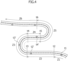
- the vehicle is running in a curved section Z1 at 4th gear, and the ACC controller 10 performs only speed control for maintaining a set vehicle speed because the curvature is less than a predetermined curvature (step 100).
- the speed control for maintaining the set vehicle speed is continued even when time t2 has passed and the vehicle enters a straight section Z2.
- the ACC controller 10 refers to the curve driving history (step 112).
- the ACC controller 10 makes a deceleration request so as to decelerate the vehicle to a vehicle speed which enables the vehicle to stably run in the curved section Z3, and at the same time, the ACC controller 10 restricts the shift gear to an upper limit 1 gear (step 113).
- the AMT controller 40 In response to the deceleration request (torque down request) of the ACC controller 10, the AMT controller 40 upshifts to 5th gear. However, since the shift gear is restricted to the upper limit of 1 gear during the predetermined time T1, upshift to 6th gear is not performed (step 113).
- the ACC controller 10 refers to the curve driving history (step 112). Since there is a curve driving history within the predetermined time T2 (step 112; NO), the ACC controller 10 makes a deceleration request to decelerate the vehicle to a vehicle speed which enables the vehicle to stably run on the curved section Z5, and at the same time, prohibits the shift gear (step 115). Following the above operation, the gear position is fixed to 4th gear during running on the curved section Z5.
- step 120 the shift restriction is canceled (step 120).
- acceleration is started immediately in response to an acceleration request (torque up request) for setting the set vehicle speed to a target vehicle speed.
- torque up request an acceleration request for setting the set vehicle speed to a target vehicle speed.
- the time-count of the predetermined time T2 is continued from the time t5, and the curve running history in the curved section Z5 is retained.
- the curve driving assist function operates on the assumption of ACC driving. Therefore, when the ACC function is overridden due to intervention by a driver's brake operation or accelerator operation, the shift restriction is canceled, and the curve driving assist function is also stopped.
- the time-count of the predetermined time T2 for which the curve driving history is retained is started from the time point when the curve driving condition is satisfied has been described, but the time-count of the predetermined time T2 (T2') may be started from the time point when the vehicle has passed through the curved section and the curve driving end condition is satisfied.
- a switch which can be manually operated by a driver for example, a mountain road mode switch, may be set, and in a state in which the mountain road mode switch is turned on and a mountain road mode (shift gear prohibition mode) is specified, the shift gear may be prohibited immediately when the curve driving condition is satisfied.
- FIG 3 is a flowchart showing a second example of the curve driving assist function including the mountain road mode switch, and description will be made with reference to Figures 3 and 4 .
- step 101 When the mountain road mode switch is turned on (step 101; YES) during ACC driving (step 100), for example, when the vehicle is running on the straight section Z2 in 4th gear, the curved section Z3 having a predetermined curvature or greater is detected ahead on the running road at time t2', and the curve driving condition is satisfied at time t3 (step 102; YES), the ACC controller 10 makes a deceleration request for decelerating the vehicle to a vehicle speed at which the vehicle can stably run in the curved section Z3, and at the same time, prohibits the shift gear (step 103). As a result, the gear position is fixed in 4th gear during running on the curved section Z3.
- step 120 the shift restriction is canceled (step 120).
- acceleration is immediately started in response to an acceleration request (torque up request) for setting the set vehicle speed to a target vehicle speed.
- the ACC controller 10 makes a deceleration request for decelerating the vehicle to a vehicle speed at which the vehicle can stably run in the curved section Z5, and at the same time, prohibits the shift gear (step 103).
- the curve assist function in the vehicle having the ACC function has been described, but the present invention can be implemented as a curve assist function in a vehicle including an LKA (Lane Keeping Assist) function for recognizing the driving lane of a vehicle with the front detecting means of the vehicle which is exemplified as the front camera 14 and the vehicle-ahead detecting means 11, and performing automatic steering or assist steering so that running within the driving lane of the vehicle is maintained, and a vehicle equipped with ADAS (Advanced Driving Assist System) in which an ACC function (control in vehicle length direction) and an LKA function (control in vehicle width direction) are combined with each other.
- LKA Long Keeping Assist
- ADAS Advanced Driving Assist System
Landscapes
- Engineering & Computer Science (AREA)
- General Engineering & Computer Science (AREA)
- Mechanical Engineering (AREA)
- Control Of Transmission Device (AREA)
- Control Of Driving Devices And Active Controlling Of Vehicle (AREA)
Claims (5)
- Appareil de commande (10) pour un véhicule (1) comportant une transmission automatique (4) de type échelonné, l'appareil de commande (10) ayant :une fonction de régulateur de vitesse adaptatif, ACC, consistant à amener un véhicule (1) à se déplacer à une vitesse de véhicule définie lorsqu'aucun véhicule devant n'est présent dans une voie de circulation du véhicule (1), et à faire une demande d'accélération/demande de décélération pour amener le véhicule (1) à se déplacer tout en suivant un véhicule devant avec un maintien d'un temps entre véhicules défini par rapport au véhicule devant lorsque le véhicule devant est présent dans la voie de circulation du véhicule (1) ; etune fonction d'aide à la conduite dans un virage pour faire une demande de décélération lorsqu'une condition de conduite dans un virage est remplie en détectant une entrée dans un virage ayant une courbure prédéterminée ou plus et en estimant que la vitesse de véhicule dépasse la vitesse de véhicule qui permet un déplacement stable dans le virage,et caractérisé en ce quel'appareil de commande (10) est configuré pour restreindre une limite supérieure d'un changement de vitesse de la transmission automatique (4) à 1 vitesse si la condition de conduite dans un virage est remplie pendant le déplacement sur la base de la fonction ACC.
- Appareil de commande (10) pour un véhicule (1) selon la revendication 1, dans lequel l'appareil de commande (10) est configuré pour conserver un historique de conduite dans un virage si la condition de conduite dans un virage est remplie, et par la suite(i) effacer l'historique de conduite dans un virage si une condition de conduite dans un virage suivante n'est pas remplie dans un premier temps prédéterminé, ou(ii) conserver l'historique de conduite dans un virage si la condition de conduite dans un virage suivante est remplie dans le premier temps prédéterminé, et ensuite interdire un changement de vitesse jusqu'à ce que l'historique de conduite dans un virage soit effacé.
- Appareil de commande (10) pour un véhicule (1) selon la revendication 1 ou 2, dans lequel l'appareil de commande (10) est configuré pour lancer un comptage de temps d'un second temps prédéterminé si la condition de conduite dans un virage est remplie, et réinitialiser la restriction du changement de vitesse si la condition de conduite dans un virage est remplie lorsque le second temps prédéterminé s'est écoulé.
- Appareil de commande (10) pour un véhicule selon l'une quelconque des revendications 1 à 3, dans lequel l'appareil de commande (10) est configuré pour interdire un changement de vitesse si la condition de conduite dans un virage est remplie dans un état dans lequel un mode d'interdiction de changement de vitesse est spécifié en allumant un commutateur pouvant être activé artificiellement.
- Appareil de commande (10) pour un véhicule (1) selon l'une quelconque des revendications 1 à 4, dans lequel la transmission automatique est une transmission automatique (4) de type transmission manuelle automatisée, AMT, comprenant un embrayage (3) pour transmettre une sortie d'un moteur (2) à un mécanisme de transmission, un actionneur d'embrayage pour embrayer et débrayer au moyen de l'embrayage (3), un actionneur de transmission pour changer une position de vitesse du mécanisme de transmission, et un dispositif de commande AMT (40) pour commander l'actionneur de transmission et l'actionneur d'embrayage pour exécuter le changement de vitesse.
Applications Claiming Priority (1)
| Application Number | Priority Date | Filing Date | Title |
|---|---|---|---|
| JP2021171027A JP2023061188A (ja) | 2021-10-19 | 2021-10-19 | 車両の制御装置 |
Publications (2)
| Publication Number | Publication Date |
|---|---|
| EP4170203A1 EP4170203A1 (fr) | 2023-04-26 |
| EP4170203B1 true EP4170203B1 (fr) | 2024-04-24 |
Family
ID=83191966
Family Applications (1)
| Application Number | Title | Priority Date | Filing Date |
|---|---|---|---|
| EP22193768.3A Active EP4170203B1 (fr) | 2021-10-19 | 2022-09-02 | Appareil de commande pour véhicule |
Country Status (2)
| Country | Link |
|---|---|
| EP (1) | EP4170203B1 (fr) |
| JP (1) | JP2023061188A (fr) |
Family Cites Families (4)
| Publication number | Priority date | Publication date | Assignee | Title |
|---|---|---|---|---|
| JP4014358B2 (ja) * | 2000-10-11 | 2007-11-28 | トヨタ自動車株式会社 | 車両用変速制御装置 |
| JP3648444B2 (ja) * | 2000-10-11 | 2005-05-18 | トヨタ自動車株式会社 | 車両用変速制御装置 |
| JP2008068752A (ja) | 2006-09-14 | 2008-03-27 | Mazda Motor Corp | 車両の走行制御装置 |
| JP7234899B2 (ja) * | 2019-10-29 | 2023-03-08 | トヨタ自動車株式会社 | 車両およびその制御方法 |
-
2021
- 2021-10-19 JP JP2021171027A patent/JP2023061188A/ja active Pending
-
2022
- 2022-09-02 EP EP22193768.3A patent/EP4170203B1/fr active Active
Also Published As
| Publication number | Publication date |
|---|---|
| JP2023061188A (ja) | 2023-05-01 |
| EP4170203A1 (fr) | 2023-04-26 |
Similar Documents
| Publication | Publication Date | Title |
|---|---|---|
| US10654487B2 (en) | Travel control apparatus of self-driving vehicle | |
| EP2738412B1 (fr) | Dispositif de commande de véhicule | |
| CN109760667B (zh) | 车辆控制装置 | |
| US20080033621A1 (en) | Vehicle travel controller | |
| CN110126827B (zh) | 车辆行驶控制装置 | |
| JP6776968B2 (ja) | 走行制御装置、車両および走行制御方法 | |
| WO2013046381A1 (fr) | Appareil de commande de véhicule | |
| JP6630753B2 (ja) | 走行態様認識装置 | |
| US20110307152A1 (en) | Vehicle travel control device | |
| WO2013020760A1 (fr) | Procédé permettant d'influer sur une stratégie de changement de vitesse d'un véhicule automobile | |
| US10990098B2 (en) | Vehicle control apparatus | |
| JP6580107B2 (ja) | 車両制御装置 | |
| JP2019137195A (ja) | 車両走行制御装置 | |
| US10691124B2 (en) | Control apparatus for vehicle | |
| CN110040142B (zh) | 车辆行驶控制装置 | |
| KR101724475B1 (ko) | 자차와 전방 차량 사이의 상대 속도에 기초하여 변속을 제어하는 방법 및 장치 | |
| WO2018168459A1 (fr) | Dispositif de commande de boîte de vitesses pour véhicule | |
| CN210126520U (zh) | 车辆的控制装置 | |
| CN210126518U (zh) | 车辆控制装置 | |
| JP2006224882A (ja) | 車両の減速制御装置 | |
| EP4170203B1 (fr) | Appareil de commande pour véhicule | |
| US11022214B2 (en) | Transmission control device | |
| JP2006071084A (ja) | 車両用駆動力制御装置 | |
| WO2015107914A1 (fr) | Système, procédé, et programme de commande de véhicule | |
| JP5257382B2 (ja) | 車両制御システム |
Legal Events
| Date | Code | Title | Description |
|---|---|---|---|
| PUAI | Public reference made under article 153(3) epc to a published international application that has entered the european phase |
Free format text: ORIGINAL CODE: 0009012 |
|
| STAA | Information on the status of an ep patent application or granted ep patent |
Free format text: STATUS: REQUEST FOR EXAMINATION WAS MADE |
|
| 17P | Request for examination filed |
Effective date: 20220902 |
|
| AK | Designated contracting states |
Kind code of ref document: A1 Designated state(s): AL AT BE BG CH CY CZ DE DK EE ES FI FR GB GR HR HU IE IS IT LI LT LU LV MC MK MT NL NO PL PT RO RS SE SI SK SM TR |
|
| GRAP | Despatch of communication of intention to grant a patent |
Free format text: ORIGINAL CODE: EPIDOSNIGR1 |
|
| STAA | Information on the status of an ep patent application or granted ep patent |
Free format text: STATUS: GRANT OF PATENT IS INTENDED |
|
| INTG | Intention to grant announced |
Effective date: 20231129 |
|
| GRAS | Grant fee paid |
Free format text: ORIGINAL CODE: EPIDOSNIGR3 |
|
| GRAA | (expected) grant |
Free format text: ORIGINAL CODE: 0009210 |
|
| STAA | Information on the status of an ep patent application or granted ep patent |
Free format text: STATUS: THE PATENT HAS BEEN GRANTED |
|
| AK | Designated contracting states |
Kind code of ref document: B1 Designated state(s): AL AT BE BG CH CY CZ DE DK EE ES FI FR GB GR HR HU IE IS IT LI LT LU LV MC MK MT NL NO PL PT RO RS SE SI SK SM TR |
|
| REG | Reference to a national code |
Ref country code: GB Ref legal event code: FG4D |
|
| REG | Reference to a national code |
Ref country code: CH Ref legal event code: EP |
|
| REG | Reference to a national code |
Ref country code: DE Ref legal event code: R096 Ref document number: 602022003040 Country of ref document: DE |
|
| REG | Reference to a national code |
Ref country code: IE Ref legal event code: FG4D |