EP4169860A1 - Yarn threading unit and combined yarn producing device - Google Patents
Yarn threading unit and combined yarn producing device Download PDFInfo
- Publication number
- EP4169860A1 EP4169860A1 EP22202065.3A EP22202065A EP4169860A1 EP 4169860 A1 EP4169860 A1 EP 4169860A1 EP 22202065 A EP22202065 A EP 22202065A EP 4169860 A1 EP4169860 A1 EP 4169860A1
- Authority
- EP
- European Patent Office
- Prior art keywords
- yarns
- group
- yarn
- box body
- yarn threading
- Prior art date
- Legal status (The legal status is an assumption and is not a legal conclusion. Google has not performed a legal analysis and makes no representation as to the accuracy of the status listed.)
- Granted
Links
Images











Classifications
-
- B—PERFORMING OPERATIONS; TRANSPORTING
- B65—CONVEYING; PACKING; STORING; HANDLING THIN OR FILAMENTARY MATERIAL
- B65H—HANDLING THIN OR FILAMENTARY MATERIAL, e.g. SHEETS, WEBS, CABLES
- B65H57/00—Guides for filamentary materials; Supports therefor
- B65H57/003—Arrangements for threading or unthreading the guide
-
- B—PERFORMING OPERATIONS; TRANSPORTING
- B65—CONVEYING; PACKING; STORING; HANDLING THIN OR FILAMENTARY MATERIAL
- B65H—HANDLING THIN OR FILAMENTARY MATERIAL, e.g. SHEETS, WEBS, CABLES
- B65H57/00—Guides for filamentary materials; Supports therefor
- B65H57/02—Stationary rods or plates
-
- B—PERFORMING OPERATIONS; TRANSPORTING
- B65—CONVEYING; PACKING; STORING; HANDLING THIN OR FILAMENTARY MATERIAL
- B65H—HANDLING THIN OR FILAMENTARY MATERIAL, e.g. SHEETS, WEBS, CABLES
- B65H57/00—Guides for filamentary materials; Supports therefor
- B65H57/16—Guides for filamentary materials; Supports therefor formed to maintain a plurality of filaments in spaced relation
-
- B—PERFORMING OPERATIONS; TRANSPORTING
- B65—CONVEYING; PACKING; STORING; HANDLING THIN OR FILAMENTARY MATERIAL
- B65H—HANDLING THIN OR FILAMENTARY MATERIAL, e.g. SHEETS, WEBS, CABLES
- B65H2701/00—Handled material; Storage means
- B65H2701/30—Handled filamentary material
- B65H2701/31—Textiles threads or artificial strands of filaments
- B65H2701/313—Synthetic polymer threads
- B65H2701/3132—Synthetic polymer threads extruded from spinnerets
-
- B—PERFORMING OPERATIONS; TRANSPORTING
- B65—CONVEYING; PACKING; STORING; HANDLING THIN OR FILAMENTARY MATERIAL
- B65H—HANDLING THIN OR FILAMENTARY MATERIAL, e.g. SHEETS, WEBS, CABLES
- B65H2701/00—Handled material; Storage means
- B65H2701/30—Handled filamentary material
- B65H2701/38—Thread sheet, e.g. sheet of parallel yarns or wires
Definitions
- the present invention relates to a yarn threading unit used for a combined yarn producing device configured such that: a plurality of yarns supplied from a spinning device are divided into a first group of yarns and a second group of yarns, of which at least the first group of yarns are drawn; and thereafter, the first group of yarns are combined with the second group of yarns to produce a bi-shrinkage yarn.
- a combined yarn producing device is equipped with the yarn threading unit.
- a fully drawn yarn (FDY) formed as a result of drawing yarns, and a partially oriented yarn (POY) formed without any drawing yarns are different in shrinkage ratio from each other.
- a bi-shrinkage yarn (BSY) formed as a result of doubling two sorts of yarns mutually different in shrinkage ratio has been known as having a good texture, and devices for producing such a bi-shrinkage yarn have been proposed conventionally.
- Patent Document 1 Japanese Patent Application Publication No. 2021-102835
- a yarn threading operation has been performed in such a manner that a plurality of yarns supplied from a spinning device are divided into a first group of yarns and a second group of yarns, of which: the second group of yarns are wound onto a guide roller; and the first group of yarns are wound onto a plurality of godet rollers each having heating means, while the plurality of yarns being suctioned by a suction gun.
- a yarn threading operation when dividing the plurality of yarns into the first group of yarns and the second group of yarns, an operator had to hold a suction gun with one hand while holding with the other hand an instrument for dividing yarns whose distal end likely to hook yarns.
- the plurality of supplied yarns are divided into the first group of yarns and the second group of yarns by the instrument for dividing yarns held with the operator's other hand.
- the second group of yarns are wound onto the guide roller and the first group of yarns are wound sequentially onto the plurality of godet rollers while manipulating a position of the suction gun by the operator.
- the present invention has been made in view of the above-described circumstances, and it is the objective of the present invention to provide a yarn threading unit and a combined yarn producing device equipped with the yarn threading unit configured in such a manner that: a yarn threading operation of winding a first group of yarns sequentially onto a plurality of godet rollers can be easily performed by the operator as a result of manipulating a suction gun with his or her both hands; an operation time necessary for such a yarn threading operation can be largely reduced; and a yarn waste generated in such a yarn threading operation can be largely reduced as a result of reducing an amount of yarns suctioned into the suction gun.
- the yarn threading unit when performing a yarn threading operation in the combined yarn producing device in the production of bi-shrinkage yarns, firstly, the yarn threading unit is arranged on the box body of the thermal insulation box at the edge of the box body closer to the guide roller than the plurality of godet rollers. At such a stage of operation, the yarn threading portion of the yarn threading unit is arranged so as to extend along the edge of the box body at a position protruding from the end surfaces of the plurality of godet rollers in an axial direction of the plurality of godet rollers. Secondary, in such a state, the yarn threading operation is performed.
- the operator manipulates the suction gun in such a manner that the suction gun suctions the plurality of yarns supplied from the spinning device and divides the plurality of yarns into the first group of yarns and the second group of yarns.
- the second group of yarns separated from the first group of yarns are wound onto the guide roller arranged at a position closer to the yarn threading unit than the plurality of godet rollers.
- the operator holding the suction gun for suctioning the plurality of yarns with both hands manipulates its position so as to perform the operations of winding the first group of yarns sequentially onto the plurality of godet rollers.
- the second group of yarns wound onto the guide roller suctioned by the suction gun are threaded, on a yarn path for handling the second group of yarns from the guide roller to a suction opening of the suction gun, through the yarn threading portion of the yarn threading unit extending along the edge of the box body at a position protruding toward an outside of the box body from the plurality of godet rollers in an axial direction of the plurality of godet rollers.
- a state is maintained where the second group of yarns are threaded through the yarn threading portion of the yarn threading unit.
- a state is maintained where a portion on a yarn path for handling the second group of yarns between the guide roller and the suction gun takes a roundabout route with respect to a position protruding toward an outside of the box body from the end surfaces of the plurality of godet rollers in an axial direction of the plurality of godet rollers.
- a yarn threading unit where: a yarn threading operation of winding a first group of yarns sequentially onto a plurality of godet rollers can be easily performed by the operator as a result of manipulating a suction gun with his or her both hands; an operation time necessary for such a yarn threading operation can be largely reduced; and a yarn waste generated in such a yarn threading operation can be largely reduced as a result of reducing an amount of yarns suctioned into the suction gun.
- the yarn threading portion may have a rod-like portion extending in a straight-line shape along an edge of the box body arranged closer to the guide roller than the plurality of godet rollers in a state where the attachment portion is attached to the box body.
- the yarn threading unit can be easily formed with a simple structure including the yarn threading portion having the rod-like portion extending in a straight-line shape and the attachment portion for attaching the yarn threading unit to the box body.
- the yarn threading unit which enables the operator to easily perform the yarn threading operation of winding the first group of yarns onto the plurality of godet rollers while manipulating the suction gun with both hands so as to maintain a state of dividing a yarn path for handling the first group of yarns and a yarn path for handling the second group of yarns, can be easily formed with a simple structure.
- the yarn threading portion may have a portion extending in a flat-plate-like shape along an edge of the box body arranged closer to the guide roller than the plurality of godet rollers in a state where the attachment portion is attached to the box body.
- the yarn threading unit can be easily formed with a simple structure including the yarn threading portion having the portion extending in a flat-plate-like shape and the attachment portion for attaching the yarn threading unit to the box body.
- the yarn threading unit which enables the operator to easily perform the yarn threading operation of winding the first group of yarns onto the plurality of godet rollers while manipulating the suction gun with both hands so as to maintain a state of dividing a yarn path for handling the first group of yarns and a yarn path for handling the second group of yarns, can be easily formed with a simple structure.
- the yarn threading unit according to the present invention does not necessarily include all the above-described first aspect [1] to third aspect [3].
- the invention in the above-described first aspect [1] of the yarn threading unit does not need to encompass all the inventions of the above-described second aspect [2] and third aspect [3].
- the present invention may be obtained by combining arbitrarily the above-described first aspect [1] of the yarn threading unit with a part of the above-described second aspect [2] and third aspect [3] to such an extent that consistency can be achieved.
- the yarn threading unit according to the present invention may be obtained by combining, e.g ., the above-described first aspect [1] of the yarn threading unit with the above-described second aspect [2].
- the yarn threading unit according to the present invention may be obtained by combining, e.g., the above-described first aspect [1] of the yarn threading unit with the above-described third aspect [3].
- a yarn threading unit of a combined yarn producing device wherein the combined yarn producing device includes a plurality of godet rollers with a heating source configured such that at least a first group of yarns obtained as a result of dividing a plurality of yarns supplied from a spinning device into some portions as the first group of yarns and other portion than the first group of yarns as a second group of yarns are wound onto the plurality of godet rollers, and heated to be drawn by the plurality of godet rollers, a thermal insulation box having a box body configured to accommodate the plurality of godet rollers and a door for opening and closing the box body, and a guide roller configured to guide the second group of yarns, thereby doubling the first group of yarns and the second group of yarns to produce bi-shrinkage yarns, and wherein the yarn threading unit is used when winding the first group of yarns onto the plurality
- the yarn threading unit when performing a yarn threading operation in the combined yarn producing device in the production of bi-shrinkage yarns, firstly, the yarn threading unit is arranged on the box body of the thermal insulation box at the edge of the side wall of the box body arranged with the guide roller as well as separated from the plurality of godet rollers. At such a stage of operation, the yarn threading portion of the yarn threading unit is arranged so as to extend along the edge of the side wall of the box body at a position protruding from the end surfaces of the plurality of godet rollers in an axial direction of the plurality of godet rollers. Secondary, in such a state, the yarn threading operation is performed.
- the operator manipulates the suction gun in such a manner that the suction gun suctions the plurality of yarns supplied from the spinning device and divides the plurality of yarns into the first group of yarns and the second group of yarns.
- the second group of yarns separated from the first group of yarns are wound onto the guide roller arranged at the side wall of the box body arranged with the yarn threading unit as well as separated from the plurality of godet rollers.
- the operator holding the suction gun for suctioning the plurality of yarns with both hands manipulates its position so as to perform the operations of winding the first group of yarns sequentially onto the plurality of godet rollers.
- the second group of yarns wound onto the guide roller suctioned by the suction gun are threaded, on a yarn path for handling the second group of yarns from the guide roller to a suction opening of the suction gun, through the yarn threading portion of the yarn threading unit extending along the edge of the side wall of the box body at a position protruding toward an outside of the box body from the plurality of godet rollers in an axial direction of the plurality of godet rollers.
- a state is maintained where the second group of yarns are threaded through the yarn threading portion of the yarn threading unit.
- a state is maintained where a portion on a yarn path for handling the second group of yarns between the guide roller and the suction gun takes a roundabout route with respect to a position protruding toward an outside of the box body from the end surfaces of the plurality of godet rollers in an axial direction of the plurality of godet rollers.
- a yarn threading unit where: a yarn threading operation of winding a first group of yarns sequentially onto a plurality of godet rollers can be easily performed by the operator as a result of manipulating a suction gun with his or her both hands; an operation time necessary for such a yarn threading operation can be largely reduced; and a yarn waste generated in such a yarn threading operation can be largely reduced as a result of reducing an amount of yarns suctioned into the suction gun.
- a combined yarn producing device comprising: a plurality of godet rollers with a heating source configured such that at least a first group of yarns obtained as a result of dividing a plurality of yarns supplied from a spinning device into some portion as the first group of yarns and other portion than the first group of yarns as a second group of yarns are wound onto the plurality of godet rollers, and heated to be drawn by the plurality of godet rollers; a thermal insulation box having a box body configured to accommodate the plurality of godet rollers and a door for opening and closing the box body; a guide roller configured to guide the second group of yarns; a yarn doubling device configured to double the first group of yarns and the second group of yarns thereby to produce bi-shrinkage yarns; and a yarn threading unit to be used when winding the first group of yarns onto the plurality of godet rollers while
- the yarn threading unit when performing a yarn threading operation in the production of bi-shrinkage yarns, firstly, the yarn threading unit is arranged on the box body of the thermal insulation box at the edge of the box body closer to the guide roller than the plurality of godet rollers. At such a stage of operation, the yarn threading portion of the yarn threading unit is arranged so as to extend along the edge of the box body at a position protruding from the end surfaces of the plurality of godet rollers in an axial direction of the plurality of godet rollers. Secondary, in such a state, the yarn threading operation is performed.
- the operator manipulates the suction gun in such a manner that the suction gun suctions the plurality of yarns supplied from the spinning device and divides the plurality of yarns into the first group of yarns and the second group of yarns.
- the second group of yarns separated from the first group of yarns are wound onto the guide roller arranged at a position closer to the yarn threading unit than the plurality of godet rollers.
- the operator holding the suction gun for suctioning the plurality of yarns with both hands manipulates its position so as to perform the operations of winding the first group of yarns sequentially onto the plurality of godet rollers.
- the second group of yarns wound onto the guide roller suctioned by the suction gun are threaded, on a yarn path for handling the second group of yarns from the guide roller to a suction opening of the suction gun, through the yarn threading portion of the yarn threading unit extending along the edge of the box body at a position protruding toward an outside of the box body from the plurality of godet rollers in an axial direction of the plurality of godet rollers.
- a state is maintained where the second group of yarns are threaded through the yarn threading portion of the yarn threading unit.
- a state is maintained where a yarn path for handling the second group of yarns between the guide roller and the suction gun takes a roundabout route with respect to a position protruding toward an outside of the box body from the end surfaces of the plurality of godet rollers in an axial direction of the plurality of godet rollers.
- a yarn threading operation of winding a first group of yarns sequentially onto a plurality of godet rollers can be easily performed by the operator as a result of manipulating a suction gun with his or her both hands; an operation time necessary for such a yarn threading operation can be largely reduced; and a yarn waste generated in such a yarn threading operation can be largely reduced as a result of reducing an amount of yarns suctioned into the suction gun.
- a combined yarn producing device comprising: a plurality of godet rollers with a heating source configured such that at least a first group of yarns obtained as a result of dividing a plurality of yarns supplied from a spinning device into some portion as the first group of yarns and other portion than the first group of yarns as a second group of yarns are wound onto the plurality of godet rollers, and heated to be drawn by the plurality of godet rollers; a thermal insulation box having a box body configured to accommodate the plurality of godet rollers and a door for opening and closing the box body; a guide roller configured to guide the second group of yarns; a yarn doubling device configured to double the first group of yarns and the second group of yarns thereby to produce bi-shrinkage yarns; and a yarn threading unit to be used when winding the first group of yarns onto the plurality of godet rollers while
- the yarn threading unit when performing a yarn threading operation in the production of bi-shrinkage yarns, firstly, the yarn threading unit is arranged on the box body of the thermal insulation box at the edge of the side wall of the box body arranged with the guide roller as well as separated from the plurality of godet rollers. At such a stage of operation, the yarn threading portion of the yarn threading unit is arranged so as to extend along the edge of the side wall of the box body at a position protruding from the end surfaces of the plurality of godet rollers in an axial direction of the plurality of godet rollers. Secondary, in such a state, the yarn threading operation is performed.
- the operator manipulates the suction gun in such a manner that the suction gun suctions the plurality of yarns supplied from the spinning device and divides the plurality of yarns into the first group of yarns and the second group of yarns.
- the second group of yarns separated from the first group of yarns are wound onto the guide roller arranged at the side wall of the box body arranged with the yarn threading unit as well as separated from the plurality of godet rollers.
- the operator holding the suction gun for suctioning the plurality of yarns with both hands manipulates its position so as to perform the operations of winding the first group of yarns sequentially onto the plurality of godet rollers.
- the second group of yarns wound onto the guide roller suctioned by the suction gun are threaded, on a yarn path for handling the second group of yarns from the guide roller to a suction opening of the suction gun, through the yarn threading portion of the yarn threading unit extending along the edge of the side wall of the box body at a position protruding toward an outside of the box body from the plurality of godet rollers in an axial direction of the plurality of godet rollers.
- a state is maintained where the second group of yarns are threaded through the yarn threading portion of the yarn threading unit.
- a state is maintained where a portion on a yarn path for handling the second group of yarns between the guide roller and the suction gun takes a roundabout route with respect to a position protruding toward an outside of the box body from the end surfaces of the plurality of godet rollers in an axial direction of the plurality of godet rollers.
- a yarn threading operation of winding a first group of yarns sequentially onto a plurality of godet rollers can be easily performed by the operator as a result of manipulating a suction gun with his or her both hands; an operation time necessary for such a yarn threading operation can be largely reduced; and a yarn waste generated in such a yarn threading operation can be largely reduced as a result of reducing an amount of yarns suctioned into the suction gun.
- a yarn threading unit and a combined yarn producing device equipped with such a yarn threading unit where: a yarn threading operation of winding a first group of yarns sequentially onto a plurality of godet rollers can be easily performed by the operator as a result of manipulating a suction gun with his or her both hands; an operation time necessary for such a yarn threading operation can be largely reduced; and a yarn waste generated in such a yarn threading operation can be largely reduced as a result of reducing an amount of yarns suctioned into the suction gun.
- the present invention is broadly applicable to various applications as a yarn threading unit used in a combined yarn producing device where a bi-shrinkage yarn is produced by dividing a plurality of yarns supplied from a spinning device into a first group of yarns and a second group of yarns, by applying drawing to at least the first group of yarns and, thereafter, by combining the first group of yarns and the second group of yarns, and a combined yarn producing device equipped with a yarn threading unit.
- FIG. 1 is a view illustrating a combined yarn producing device 1 in which a yarn threading unit 5 (see FIG. 4 ) according to a first embodiment of the present invention is used and a combined yarn producing device according to the first embodiment of the present invention.
- FIG. 1 is also a front view illustrating the combined yarn producing device 1 that produces a bi-shrinkage yarn without applying a heat set (heat treatment) to partially oriented yarns.
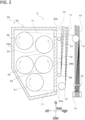
- FIG. 2 is a front view illustrating a yarn drawing device 3 in the combined yarn producing device 1 illustrated in FIG. 1 .
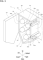
- FIG. 3 is a perspective view of the yarn drawing device 3 illustrated in FIG. 2 .
- FIG. 4 is a perspective view illustrating a yarn threading unit 5 according to the first embodiment of the present invention.
- the yarn threading unit 5 according to the first embodiment of the present invention is used in the combined yarn producing device 1 illustrated in FIG. 1 .
- the combined yarn producing device 1 according to the first embodiment of the present invention is formed as a device that includes the combined yarn producing device 1 illustrated in FIG. 1 and the yarn threading unit 5 illustrated in FIG. 4 .
- the up and down directions, the forward and backward directions, and the left and right directions in the combined yarn producing device 1 are defined as illustrated in FIG. 1 to FIG. 3 .
- the combined yarn producing device 1 is a system where a plurality of yarns Y that constitute synthetic fiber yarns formed by solidifying a molten resin continuously supplied from a spinning device 2 are divided into a first group of yarns Y1 and a second group of yarns Y2, and drawing is applied to the first group of yarns Y1 thus making shrinkage ratios of the first group of yarns Y1 and the second group of yarns Y2 different from each other.
- the first group of yarns Y1 are formed into fully drawn yarns (FDY) by applying drawing
- second group of yarns Y2 are formed into partially oriented yarns (POY) by not applying drawing thus making the first group of yarns Y1 and the second group of yarns Y2 as yarns that have different shrinkage ratios.
- the combined yarn producing device 1 combines the first group of yarns Y1 that are fully drawn yarns (FDY) and the second group of yarns Y2 that are partially oriented yarns (POY) thus producing bi-shrinkage yarns (BSY) Y3.
- the bi-shrinkage yarns Y3 that are formed of two kinds of yarns Y1, Y2 having different shrinkage ratios are known as yarns having a favorable texture.
- the yarn is simply expressed as the yarn Y.
- the combined yarn producing device 1 includes the yarn drawing device 3, a winding device 4, a yarn dividing guide 11, yarn feed rollers 12 to 15, and a yarn doubling device 16.
- the yarn dividing guide 11 is, for example, a comb-shaped guide, and is arranged below a spinning device 2.
- a plurality of all yarns Y supplied from the spinning device 2 is divided into the first group of yarns Y1 and the second group of yarns Y2 half by half by the yarn dividing guide 11.
- the plurality of yarns Y supplied from the spinning device 2 is sixteen, the plurality of yarns Y is divided into eight yarns Y1 belonging to the first group and eight yarns Y2 belonging to the second group, and eventually eight bi-shrinkage yarns Y3 are produced.
- the yarn feed rollers 12 to 15 are rotatably driven by an electrically operated motor not illustrated in the drawings.
- the yarn feed rollers 12 and 13 have rotary shafts extending in the longitudinal direction.
- the yarn feed roller 12 is arranged between the yarn dividing guide 11 and a thermal insulation box 30 described later in the yarn drawing device 3 in a yarn traveling direction of the first group of yarns Y1.
- the yarn feed rollers 13 to 15 are arranged between the yarn drawing device 3 and the winding device 4 in the yarn traveling direction of the yarn Y.
- the first group of yarns Y1 pass through the yarn dividing guide 11 and, thereafter, are introduced into the thermal insulation box 30 of the yarn drawing device 3 via the yarn feed roller 12.
- the second group of yarns Y2 pass through the yarn dividing guide 11 and, thereafter, are supplied to the yarn feed roller 13 via guide rollers 36, 37 described later in the yarn drawing device 3.
- the first group of yarns Y1 discharged from the thermal insulation box 30 of the yarn drawing device 3 and the second group of yarns Y2 fed from the guide roller 37 of the yarn drawing device 3 are fed to the yarn doubling device 16 via the yarn feed roller 13 and the yarn feed roller 14.
- the yarn doubling device 16 is arranged between the yarn feed roller 14 and the yarn feed roller 15 in the yarn traveling direction of the yarns Y.
- the yarn doubling device 16 is a device that produces the bi-shrinkage yarns Y3 by doubling the first group of yarns Y1 and the second group of yarns Y2.
- the yarn doubling device 16 is formed as an intersecting device that doubles the first group of yarns Y1 and the second group of yarns Y2 by an action of compressed air by ejecting compressed air.
- the bi-shrinkage yarns Y3 that are formed by doubling the first group of yarns Y1 and the second group of yarns Y2 by the yarn doubling device 16 are fed to the winding device 4 via the yarn feed roller 15.
- the winding device 4 includes a plurality of fulcrum guides 41, a plurality of traverse devices 42, a contact roller 43, two bobbin holders 44, and a turret 45.
- the plurality of fulcrum guides 41 and the plurality of traverse devices 42 are arranged side by side so as to correspond with each other in the longitudinal direction. In FIG. 1 , the fulcrum guide 41 and the traverse device 42 overlap with each other in the longitudinal direction.
- the plurality of bi-shrinkage yarns Y3 fed to the winding device 4 are traversed in the longitudinal direction by the corresponding traverse devices 42 about the plurality of fulcrum guides 41.
- the contact roller 43 imparts a predetermined contact pressure by coming into contact with surfaces of a plurality of packages P so as to adjust the shapes of the packages P.
- the plurality of packages P are arranged side by side in the longitudinal direction.
- FIG. 1 the plurality of packages P are illustrated in a state where the packages P overlap with each other in the longitudinal direction.
- the bobbin holder 44 extends in the longitudinal direction, and is formed such that a plurality of bobbins B are mountable on the bobbin holder 44 in a state where the plurality of bobbins B are arranged side by side in the longitudinal direction.
- the bobbin holder 44 is rotatably driven by an electrically operated motor not illustrated in the drawing.
- the turret 45 supports two bobbin holders 44 in a cantilever state, and is rotatably driven by an electrically operated motor not illustrated in the drawing. With respect to the winding device 4, by rotatably driving the turret 45, the positions of two bobbin holders 44 are switched between an upper winding position and a lower standby position.
- the winding device 4 rotates the bobbin holder 44 arranged at the upper winding position, and winds the plurality of bi-shrinkage yarns Y3 into the plurality of bobbins B thus forming the plurality of packages P.
- the turret 45 is rotated so as to switch the positions of two bobbin holders 44.
- the plurality of bi-shrinkage yarns Y3 are wound onto the plurality of bobbins B that are mounted on the bobbin holder 44 that is newly moved to the winding position.
- the yarn drawing device 3 includes the thermal insulation box 30, the plurality of (five in this embodiment) godet rollers 31 to 35 having a heat source, and a plurality of (two in this embodiment) guide rollers 36, 37.
- the first group of yarns Y1 are indicated by a chained line
- the second group of yarns Y2 are indicated by a double-dashed chained line
- the bi-shrinkage yarns Y3 are indicated by a solid line.
- the plurality of godet rollers 31 to 35 are accommodated in the thermal insulation box 30. Then, the first group of yarns Y1 that are divided as some yarns Y1 out of the plurality of yarns Y supplied from the spinning device 2 are wound onto the plurality of godet rollers 31 to 35.
- the plurality of godet rollers 31 to 35 are also provided as godet rollers for drawing the first group of yarns Y1 by heating.
- the godet rollers 31 to 35 have rotary shafts extending in the longitudinal direction, and the godet rollers 31 to 35 are respectively and rotatably driven in the direction indicated by an arrow in FIG. 2 by an electrically operated motor not illustrated in the drawing.
- Each of the godet rollers 31 to 35 incorporates a heater (heating source) not illustrated in the drawing. The heater heats the yarns Y wound onto a peripheral surface of each of the godet rollers 31 to 35. All godet rollers 31 to 35 have substantially the same outer diameter.
- each godet rollers 31 to 33 on an upstream side in the yarn traveling direction are each provided as a preheating roller for preheating the first group of yarns Y1 before the first group of yarns Y1 are drawn.
- a surface temperature of each of the godet rollers 31 to 33 that form the preheating rollers is set to a temperature equal to or more than a glass transition point of the yarn Y (for example, approximately 80°C).
- two godet rollers 34, 35 arranged on a downstream side in the yarn traveling direction are provided as heat set rollers for applying heat set (heat treatment) to the first group of yarns Y1.
- a surface temperature of each of the godet rollers 34, 35 which form the heat set rollers is set to a temperature (for example, approximately 130 to 140°C) higher than the surface temperature of the godet rollers 31 to 33 which form the preheating rollers.
- a rotational speed (that is, a yarn feed speed) of the godet rollers 34, 35 on the downstream side in the yarn traveling direction is set to a speed faster than a rotational speed (that is, a yarn feed speed) of the godet rollers 31 to 33 on the upstream side in the yarn traveling direction. Accordingly, when the first group of yarns Y1 reach the godet roller 34 via the godet rollers 31 to 33, the first group of yarns Y1 are drawn between the godet roller 33 and the godet roller 34.
- the first godet roller 31 in the yarn traveling direction (that is, on a most upstream side in the yarn traveling direction) is arranged below two remaining godet rollers 32, 33.
- the second godet roller 32 in the yarn traveling direction and the third godet roller 33 in the yarn traveling direction are arranged adjacently to each other in the lateral direction.
- An axis of the second godet roller 32 in the yarn traveling direction is positioned on a right side of an axis of the godet roller 31 on the most upstream side in the yarn traveling direction.
- An axis of the third godet roller 33 in the yarn traveling direction is positioned on a left side of the axis of the godet roller 31 on the most upstream side in the yarn traveling direction.
- Two godet rollers 34, 35 that are heat set rollers and are fourth and fifth godet rollers in the yarn traveling direction are arranged adjacently to each other in the lateral direction above the godet rollers 31 to 33.
- the fourth godet roller 34 in the yarn traveling direction is arranged adjacently to the second godet roller 32 in the yarn traveling direction and also above the second godet roller 32.
- the fifth godet roller 35 in the yarn traveling direction is arranged above the third godet roller 33 in the yarn traveling direction.
- the fifth godet roller 35 in the yarn traveling direction is arranged in an offset manner toward an upper side with respect to the fourth godet roller 34 in the yarn traveling direction. More specifically, an axis of the fifth godet roller 35 in the yarn traveling direction is positioned above an axis of the fourth godet roller 34 in the yarn traveling direction.
- five godet rollers 31 to 35 are arranged in a compact and concentrated manner in the lateral direction as well as in the vertical direction.
- the thermal insulation box 30 has: a box body 38 that is opened on a front side and accommodates the plurality of godet rollers 31 to 35; and a door 39 that opens and closes the box body 38.
- the door 39 is closed.
- the door 39 is formed as a hinged door. Further, the door 39 is rotatably mounted on a side wall 38a of the box body 38 on a left side by way of a hinge (not illustrated in the drawing).
- an inlet port 30a and an outlet port 30b are formed in a right-side side wall 38b of the box body 38.
- the inlet port 30a is formed on a lower end portion of the right-side wall 38b of the box body 38 as an opening of an inlet for introducing the first groups of yarns Y1 into the thermal insulation box 30.
- the outlet port 30b is formed in an upper end portion of the right-side side wall 38b of the box body 38.
- the outlet port 30b is formed as an opening of an outlet for discharging the first group of yarns Y1 that are heated and drawn to the outside.
- locking grooves 38c that engage with locking pawls (not illustrated in the drawing) formed on a door 39 side when the door 39 is closed are formed.
- a plurality of locking grooves 38c are formed.
- two locking grooves 38c are formed.
- Two locking grooves 38c are arranged side by side vertically along an edge portion of the right-side side wall 38b of the box body 38.
- the locking grooves 38c are formed so as to open at the edge portion of the side wall 38b of the box body 38.
- a stepped portion that engages with the locking pawl on a door 39 side is formed in the locking groove 38c.
- the locking pawls of the door 39 are inserted into the locking grooves 38c.
- the locking pawls engage with the stepped portions of the locking grooves 38c.
- the guide rollers 36, 37 are provided as guide rollers for guiding the second group of yarns Y2 that are divided from the plurality of yarns Y as the yarns Y2 other than the first group of yarns Y1.
- the guide rollers 36, 37 are arranged outside the thermal insulation box 30 and adjacently to the right-side side wall 38a of the box body 38.
- the guide rollers 36, 37 are arranged side by side vertically, wherein the guide roller 36 is arranged on a lower side and the guide roller 37 is arranged on an upper side.
- the guide roller 36 is provided as a guide roller on an upstream side in the yarn traveling direction of the second group of yarns Y2, and the guide roller 37 is arranged as a guide roller on a downstream side in the yarn traveling direction of the second group of yarns Y2.
- the guide rollers 36, 37 are rotatable rollers each having a rotary shaft extending in the longitudinal direction. It is preferable that the guide rollers 36, 37 are provided as drive rollers that are rotatably driven by electrically operated motors not illustrated in the drawing. However, the guide rollers 36, 37 may be formed as follower rollers that are rotated by a friction of the second group of yarns Y2.
- the guide rollers 36, 37 may be provided as follower rollers that are rotatable in a state where a friction between the follower roller and the second group of yarns Y2 is reduced or in a non-contact state with the second group of yarns Y2 by forming the guide rollers 36, 37 such that air is blown off from surfaces of the guide rollers 36, 37.
- a tension of the yarns Y can be adjusted corresponding to rotational speeds of the guide rollers 36, 37 and hence, a quality of the yarns Y can be easily controlled.
- the first group of yarns Y1 are introduced into the thermal insulation box 30 from the inlet port 30a via the yarn feed roller 12.
- the first group of yarns Y1 are wound onto the godet rollers 31 to 33 that form the preheating rollers and the godet rollers 34, 35 that form the heat set rollers, and travel.
- the first group of yarns Y1 are wound onto and travel in a zigzag manner in order of the godet roller 31, the godet roller 32, the godet roller 33, the godet roller 34, and the godet roller 35.
- the first group of yarns Y1 are preheated to a temperature that allows drawing by the godet rollers 31 to 33 that form the preheating rollers (a temperature equal to or more than a glass transition point).
- the first group of yarns Y1 that are preheated become drawn yarns due to a difference in yarn feed speed between the godet roller 33 and the godet roller 34.
- the first group of yarns Y1 are subjected to heat set in a drawn state by the godet rollers 34, 35.
- the second group of yarns Y2 to which heat set is applied are discharged to the outside of the thermal insulation box 30 from the outlet port 30b, and are fed to the yarn feed roller 13.
- the second group of yarns Y2 are wound onto the guide roller 36 and the guide roller 37 and travel outside the thermal insulation box 30, and fed to the yarn feed roller 13. Accordingly, the second group of yarns Y2 do not travel on the godet rollers 31 to 35 and hence, are fed to the yarn feed rollers 13 as partially oriented yarns without being heated and drawn.
- the first group of yarns Y1 and the second group of yarns Y2 that are fed via the yarn feed roller 13 reach the yarn doubling device 16 via the yarn feed roller 14.
- the first group of yarns Y1 and the second group of yarns Y2 are doubled to become the bi-shrinkage yarns Y3 by the yarn doubling device 16.
- the bi-shrinkage yarns Y3 are wound onto the winding device 4 via the yarn feed roller 15.
- FIG. 4 is a perspective view illustrating the yarn threading unit 5 according to the first embodiment of the present invention
- FIG. 5 is a side view of the yarn threading unit 5.
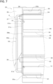
- FIG. 6 and FIG. 7 are views illustrating a state where the yarn threading unit 5 is attached to the thermal insulation box 30 of the yarn drawing device 3 of the bi-shrinkage yarns production device 1.
- FIG. 6 is a perspective view
- FIG. 7 is a side view.
- FIG. 6 and FIG. 7 illustrate a state where the door 39 of the thermal insulation box 30 is opened.
- the yarn threading unit 5 is described with reference to FIG. 4 to FIG. 7 .
- the yarn threading unit 5 is used in the combined yarn producing device 1 that produces the bi-shrinkage yarns Y3 by doubling the first group of yarns Y1 and the second group of yarns Y2.
- the yarn threading unit 5 is used in performing a yarn threading operation where the first group of yarns Y1 are wound onto the plurality of godet rollers 31 to 35 while winding the second group of yarns Y2 onto the guide roller 36.
- the yarn threading unit 5 includes an attachment portion 51 and a yarn threading portion 52.
- the attachment portion 51 is provided as a portion that is detachably attached with respect to the box body 38 of the thermal insulation box 30.
- the attachment portion 51 includes a base portion 51a and a plurality of (two in this embodiment) hook portions 51b.
- the base portion 51a is formed as a member that extends in an elongated plate shape.
- the base portion 51a is formed such that the longitudinal direction of the base portion 51a extends in a straight line shape.
- the base portion 51a is arranged in a state where the base portion 51a extends along an edge portion of the right-side side wall 38b of the box body 38.
- Two respective hook portions 51b are formed as portions that engage with the right-side side wall 38b of the box body 38 when the attachment portion 51 is attached to the box body 38.
- Each hook portion 51b is formed on the base portion 51a in an integrally joined manner, and is arranged in a protruding manner from the base portion 51a in a cantilever shape along a direction perpendicular to the longitudinal direction of the base portion 51a.
- Two hook portions 51b are formed such that these hook portions 51b protrude in the same direction from the base portion 51a.
- Two hook portions 51b are arranged at positions corresponding to two locking grooves 38c formed on the side wall 38b in a state where the attachment portion 51 is arranged along the side wall 38b of the box body 38.
- An engaging pawl 51c is formed on each hook portion 51b.
- the engaging pawl 51c is formed on a distal end side of each hook portion 51b that protrudes from the base portion 51a in a cantilever shape and in a bent hook-shaped pawl.
- the engaging pawl 51c engages with the locking groove 38c formed on the side wall 38b of the box body 38.
- the engaging pawl 51c arranged on the distal end side of each hook portion 51b engages with the stepped portion in each locking groove 38c. Due to the engagement between the engaging pawl 51c of the hook portion 51b and the stepped portion in the locking groove 38c, the attachment portion 51 is brought into a state where the attachment portion 51 is attached to the box body 38 and hence, the attachment portion 51 is held by the box body 38.
- the mode is exemplified where the attachment portion 51 is attached to the box body 38 due to the engagement between the hook portion 51b and the locking groove 38c.
- the attachment portion 51 may not be mounted in this manner, and it is sufficient that the attachment portion 51 can be detachably attached with respect to the box body 38.
- other grooves different from the locking grooves 38c may be formed on the side wall 38b of the box body 38, and the hook portions 51b may engage with the other grooves formed in the side wall 38b so that the attachment portion 51 is detachably attached with respect to the box body 38.
- a yarn threading portion 52 is formed as a portion through which the second group of yarns Y2 are threaded in a state where the attachment portion 51 is attached to the box body 38.
- the second group of yarns Y2 are threaded when a yarn threading operation using the yarn threading unit 5 is performed. Then, as illustrated in FIG. 6 and FIG.
- the yarn threading portion 52 is arranged so as to extend along an edge portion of the side wall 38b of the box body 38 closer to the guide rollers 36, 37 than the plurality of godet rollers 31 to 35 and along the edge portion of the side wall 38b of the box body 38 positioned between the plurality of godet rollers 31 to 35 and the guide rollers 36, 37 in a state where the attachment portion 51 is attached to the box body 38.
- the yarn threading portion 52 is arranged so as to extend along the edge portion of the side wall 38b of the box body 38 at a position protruding more toward the outside of the box body 38 than the plurality of godet rollers 31 to 35, the position being a position protruding from the end face portions of the plurality of godet rollers 31 to 35 in the axial direction of the godet rollers 31 to 35 in a state where the attachment portion 51 is attached to the box body 38.
- the yarn threading portion 52 includes a rod-shaped portion 52a and a pair of leg portions 52b.
- the rod-shaped portion 52a is formed as a rod-shaped portion that extends parallel to the longitudinal direction of the base portion 51a of the attachment portion 51.
- the rod-shaped portion 52a is formed as a round-rod-shaped portion that has a circular cross section and extends in a straight line shape in this embodiment.
- the rod-shaped portion 52a is formed so as to extend in a straight line shape in the vertical direction along the edge portion of the side wall 38b of the box body 38 closer to the guide rollers 36, 37 than the plurality of godet rollers 31 to 35 and along an edge portion of a front side of the side wall 38a of the box body 38 positioned between the plurality of godet rollers 31 to 35 and the guide rollers 36, 37 in a state where the attachment portion 51 is attached to the box body 38.
- the rod-shaped portion 52a is formed so as to extend over from a position corresponding to a height position of a portion of the godet roller 34 that forms an upper half of the godet roller 34 to a position that corresponds to a height position of a lower half of the godet roller 31 in the vertical direction in a state where the attachment portion 51 is attached to the box body 38.
- the pair of leg portions 52b of the yarn threading portion 52 is formed as short rod-shaped portions that protrude from the base portion 51a and support the rod-shaped portion 52a.
- the pair of respective leg portions 52b is arranged so as to protrude toward a side opposite to a side that the hook portions 51b protrude in a direction perpendicular to the longitudinal direction of the base portion 51a with respect to the base portion 51a. Further, the pair of leg portions 52b is arranged so as to protrude respectively from both end portions of the base portion 51a.
- the pair of leg portions 52b is arranged so as to protrude from an upper end portion and a lower end portion of the base portion 51a in a state where the attachment portion 51 is attached to the box body 38.
- each leg portion 52b is fixed to the base portion 51a, and the other end portion of each leg portion 52b is arranged so as to be integrally joined to the rod-shaped portion 52a.
- the other end portion of one of the pair of leg portions 52b is arranged so as to be integrally joined to one end portion out of both end portions of the rod-shaped portion 52a, and the other end portion of the other of the pair of leg portions 52b is arranged so as to be integrally joined to the other end portion out of both end portions of the rod-shaped portion 52a.
- the leg portions 52b protrude toward a forward side along the horizontal direction with respect to the edge portion of the side wall 38b of the box body 38.
- the rod-shaped portion 52a is arranged so as to extend along the vertical direction parallel to the edge portion of the side wall 38b at a position spaced apart from the edge portion of the side wall 38b of the box body 38.
- the rod-shaped portion 52a of the yarn threading portion 52 is formed so as to extend parallel to the longitudinal direction of the base portion 51a in a state where the rod-shaped portion 52a is spaced apart from the base portion 51a of the attachment portion 51 by a distance corresponding to a length of the leg portion 52b.
- the rod-shaped portion 52a of the yarn threading portion 52 extends in a straight line shape at a position spaced apart from the base portion 51a of the attachment portion 51 by the length of the leg portion 52b and hence, in a state where the attachment portion 51 is attached to the box body 38, the rod-shaped portion 52a is formed so as to extend along the edge portion of the box body 38 at a position protruding more than end face portions of the plurality of godet rollers 31 to 35 in the axial direction of the godet rollers 31 to 35.
- the attachment portion 51 and the yarn threading portion 52 are integrally formed with each other.
- the yarn threading unit 5 may not be formed in such a manner.
- the attachment portion 51 and the yarn threading portion 52 may be formed as separate bodies, and the yarn threading portion 52 may be detachably attached with the attachment portion 51.
- FIG. 8 to FIG. 14 are views illustrating a state where a yarn threading operation is performed using the yarn threading unit 5 in the combined yarn producing device 1.
- a mode in which the yarn threading operation is performed using the yarn threading unit 5 in the combined yarn producing device 1 is described with reference to FIG. 6 to FIG. 14 .
- the yarn threading operation is performed such that, first, prior to the production of the bi-shrinkage yarns Y3, the plurality of yarns Y supplied from the spinning device 2 are divided into the first group of yarns Y1 and the second group of yarns Y2, and the first group of yarns Y1 are wound onto the plurality of godet rollers 31 to 35 while winding the second group of yarns Y2 on the guide roller 36.
- the yarn threading operation as illustrated in FIG. 6 and FIG.
- the yarn threading unit 5 is attached to the box body 38 of the thermal insulation box 30 at the edge portion of the box body 38 closer to the guide rollers 36, 37 than the plurality of godet rollers 31 to 35.
- an operator not illustrated in the drawings who performs the yarn threading operation makes the hook portions 51b of the attachment portion 51 engage with the locking grooves 38c formed on the side wall 38b of the box body 38 thus attaching the yarn threading unit 5 to the box body 38.
- the yarn threading portion 52 of the yarn threading unit 5 is arranged so as to extend along the edge portion of the side wall 38b of the box body 38 at the position where the yarn threading portion 52 protrudes more than the end face portions of the plurality of godet rollers 31 to 35 in the axial direction of the godet rollers 31 to 35.
- FIG. 8 is a view illustrating a state where the first group of yarns Y1 are wound onto the yarn feed roller 12 outside the thermal insulation box 30, and the second group of yarns Y2 are wound onto the guide roller 36.
- the operator makes the suction gun 100 suction the plurality of yarns Y supplied from the spinning device 2, and divides the plurality of yarns Y into the first group of yarns Y1 and the second group of yarns Y2.
- a suction opening 100a that suctions the plurality of yarns Y is formed on a distal end of the suction gun 100, and the suction gun 100 is connected to a suction device not illustrated in the drawing.
- the operator When the plurality of yarns Y are divided into the first group of yarns Y1 and the second group of yarns Y2, the operator temporarily winds the plurality of yarns Y suctioned by the suction gun 100 onto the guide roller 36. Then, the operator holds the suction gun with one hand, and holds an instrument for dividing yarns (not illustrated in the drawings) that can hook the yarns on a distal-end-side portion with the other hand. Using the instrument for dividing the yarns that the operator holds with the other hand, the operator performs an operation of dividing the plurality of supplied yarns into the first group of yarns Y1 and the second group of yarns Y2.
- the operator winds the first group of yarns Y1 onto the yarn feed roller 12 by manipulating the instrument for dividing yarns.
- the operator releases the instrument for dividing yarns from his hand, and holds the suction gun 100 with both hands.
- the operator manipulates the position of the suction gun 100 such that the suction opening 100a of the suction gun 100 moves an area between the godet roller 31 and the yarn threading portion 52 of the yarn threading unit 5.
- the first group of yarns Y1 wound onto the yarn feed roller 12 pass through the inlet port 30a of the box body 38, and the second group of yarns Y2 wound onto the guide roller 36 pass on the rod-shaped portion 52a in a state where the second group of yarns Y2 are threaded onto an outer periphery of the rod-shaped portion 52a of the yarn threading portion 52.
- FIG. 9 is a view illustrating a state where the first group of yarns Y1 are wound onto the first godet roller 31 in the yarn traveling direction.
- the operator manipulates the position of the suction gun 100 in a state where the suction opening 100a of the suction gun 100 is inserted into the inside of the box body 38.
- the operator manipulates the suction gun 100 with both hands so as to move the suction opening 100a in a clockwise direction in FIG. 9 along an outer periphery of the godet roller 31.
- the first group of yarns Y1 are wound onto the godet roller 31 along the yarn traveling direction of the first group of yarns Y1. Further, when the first group of yarns Y1 are wound onto the godet roller 31, the second group of yarns Y2 are threaded through the yarn threading portion 52 extending at the position protruding more than the end face portion of the godet roller 31 in a yarn path from the guide roller 36 to the suction opening 100a of the suction gun 100.
- FIG. 10 is a view illustrating a state where the first group of yarns Y1 are wound onto the second godet roller 32 in the yarn traveling direction.
- the operator further manipulates the position of the suction gun 100 in a state where the suction opening 100a of the suction gun 100 is inserted into the inside of the box body 38.
- the operator manipulates the suction gun 100 with both hands such that the suction opening 100a is moved in a counterclockwise direction in FIG. 10 along an outer periphery of the godet roller 32.
- the first group of yarns Y1 are wound onto the godet roller 32 along the yarn traveling direction of the first group of yarns Y1. Further, when the first group of yarns Y1 are wound onto the godet roller 32, the second group of yarns Y2 are threaded through the yarn threading portion 52 extending at the position protruding more than the end face portion of the godet roller 32 in a yarn path from the guide roller 36 to the suction opening 100a of the suction gun 100.
- FIG. 11 is a view illustrating a state where the first group of yarns Y1 are wound onto the third godet roller 33 in the yarn traveling direction.
- the operator further manipulates the position of the suction gun 100 in a state where the suction opening 100a of the suction gun 100 is inserted into the inside of the box body 38.
- the operator manipulates the suction gun 100 with both hands such that the suction opening 100a is moved in a clockwise direction in FIG. 11 along an outer periphery of the godet roller 33.
- the first group of yarns Y1 are wound onto the godet roller 33 along the yarn traveling direction of the first group of yarns Y1. Further, when the first group of yarns Y1 are wound onto the godet roller 33, the second group of yarns Y2 are threaded through the yarn threading portion 52 extending at the position protruding more than the end face portion of the godet roller 33 in a yarn path from the guide roller 36 to the suction opening 100a of the suction gun 100.
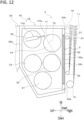
- FIG. 12 is a view illustrating a state where the first group of yarns Y1 are wound onto the fourth godet roller 34 in the yarn traveling direction.
- the operator further manipulates the position of the suction gun 100 in a state where the suction opening 100a of the suction gun 100 is inserted into the inside of the box body 38.
- the operator manipulates the suction gun 100 with both hands such that the suction opening 100a is moved in a counterclockwise direction in FIG. 12 along an outer periphery of the godet roller 34.
- the first group of yarns Y1 are wound onto the godet roller 34 along the yarn traveling direction of the first group of yarns Y1. Further, when the first group of yarns Y1 are wound onto the godet roller 34, the second group of yarns Y2 are threaded through the yarn threading portion 52 extending at the position protruding more than the end face portion of the godet roller 34 in a yarn path from the guide roller 36 to the suction opening 100a of the suction gun 100.
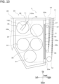
- FIG. 13 is a view illustrating a state where the first group of yarns Y1 are wound onto the fifth godet roller 35 in the yarn traveling direction.
- the operator further manipulates the position of the suction gun 100 in a state where the suction opening 100a of the suction gun 100 is inserted into the inside of the box body 38.
- the operator manipulates the suction gun 100 with both hands such that the suction opening 100a is moved in a clockwise direction in FIG. 12 along an outer periphery of the godet roller 35.
- the first group of yarns Y1 are wound onto the godet roller 35 along the yarn traveling direction of the first group of yarns Y1. Further, when the first group of yarns Y1 are wound onto the godet roller 35, the second group of yarns Y2 are threaded through the yarn threading portion 52 extending at the position protruding more than the end face portion of the godet roller 35 in a yarn path from the guide roller 36 to the suction opening 100a of the suction gun 100.
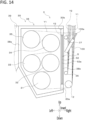
- FIG. 14 is a view illustrating a state where the first group of yarns Y1 are wound onto all godet rollers 31 to 35 and the second group of yarns Y2 are wound onto the guide rollers 36, 37.
- an operator manipulates the position of the suction gun 100 such that the suction opening 100a of the suction gun 100 passes the outlet port 30b. Accordingly, a yarn path is brought into a state where the first group of yarns Y1 pass the outlet port 30b.
- the second group of yarns Y2 that are wound onto the guide roller 36 are removed from the yarn threading portion 52 of the yarn threading unit 5. Then, the operator further manipulates the suction gun 100 with both hands so as to move the suction opening 100b of the suction gun 100 in the clockwise direction in FIG. 14 along an outer periphery of the guide roller 37. Accordingly, the second group of yarns Y2 that are wound onto the guide roller 36 are also wound onto the guide roller 37 in the traveling direction of the second group of yarns Y2.
- the yarn threading operation where the plurality of yarns Y supplied from the spinning device 2 are divided into the first group of yarns Y1 and the second group of yarns Y2, and the first group of yarns Y1 are wound onto the plurality of godet rollers 31 to 35 while winding the second group of yarns Y2 onto the guide roller 36 is completed.
- the yarn threading unit 5 in performing a yarn threading operation in the combined yarn producing device 1 in the production of the bi-shrinkage yarns Y3, first, the yarn threading unit 5 is attached to the box body 38 of the thermal insulation box 30 at the edge portion of the box body 38 closer to the guide rollers 36, 37 than the plurality of godet rollers 31 to 35.
- the yarn threading portion 52 of the yarn threading unit 5 is arranged so as to extend along the edge portion of the box body 38 at the position protruding more than the end face portions of the plurality of godet rollers 31 to 35 in the axial direction of the godet rollers 31 to 35.
- the yarn threading operation is performed.
- the operator manipulates the suction gun 100 so that the suction gun 100 suctions the plurality of yarns Y supplied from the spinning device 2 and divides the plurality of yarns Y into the first group of yarns Y1 and the second group of yarns Y2.
- the second group of yarns Y2 are wound onto the guide roller 36 arranged at the position closer to the yarn threading unit 5 than the plurality of godet rollers 31 to 35.
- the operator holds the suction gun 100 for suctioning the plurality of yarns Y with both hands, and sequentially performs the operations of winding the first group of yarns Y1 onto the plurality of godet rollers 31 to 35 by manipulating the position of the suction gun 100.
- the second group of yarns Y2 that are wound onto the guide roller 36 and are suctioned by the suction gun 100 are, in a yarn path from the guide roller 36 to the suction opening 100a of the suction gun 100, threaded through the yarn threading portion 52 of the yarn threading unit 5 extending along the edge portion of the box body 38 at the position protruding toward more outside of the box body 38 than the plurality of godet rollers 31 to 35, the position also being a position protruding more than the end face portions of the godet rollers 31 to 35 in the axial direction of the godet rollers 31 to 35.
- a state is maintained where a yarn path of the second group of yarns Y2 takes a roundabout route with respect to the position that protrudes more outside of the box body 38 than the plurality of godet rollers 31 to 35, the position also being a position protruding from the end face portions of the godet rollers 31 to 35 in the axial direction of the godet rollers 31 to 35 at a part of the portion positioned between the guide roller 36 in a yarn path of the second group of yarns Y2 and the suction gun 100.
- the operator can easily perform the yarn threading operation for sequentially winding the first group of yarns Y1 onto the plurality of godet rollers 31 to 35 while maintaining a state where a yarn path of the first group of yarns Y1 and a yarn path of the second group of yarns Y2 are divided from each other by manipulating the heavy suction gun 100 with both hands.
- the yarn threading operation can be performed easily, an operation time necessary for the yarn threading operation can be largely shortened.
- the operation time of the yarn threading operation can be largely shortened, a quantity of yarns suctioned into the suction gun 100 during the operation can be reduced and hence, the generated yarn waste can be largely reduced.
- the first embodiment according to the present invention can provide the yarn threading unit 5 and the combined yarn producing device equipped with the yarn threading unit 5 where, the yarn threading operation for sequentially winding the first group of yarns Y1 on the plurality of godet rollers 31 to 35 can be performed easily by manipulating the suction gun 100 with both hands. Further, the operation time necessary for the yarn threading operation can be largely shortened and, at the same time, a quantity of yarns suctioned into the suction gun 100 can be reduced thus largely reducing the generation of the yarn waste.
- the yarn threading unit 5 can be easily formed with the simple structure that includes: the yarn threading portion 52 having the rod-shaped portion 52a that extends in a straight line shape: and the attachment portion 51 for attaching the yarn threading unit 5 to the box body 38. That is, the yarn threading unit 5 that allows the operator to easily perform the yarn threading operation for winding the first group of yarns Y1 onto the plurality of godet rollers 31 to 35 while maintaining a state where a yarn path of the first group of yarns Y1 and a yarn path of the second group of yarns Y2 are divided from each other by manipulating the suction gun 100 with both hands can be easily formed with the simple structure.
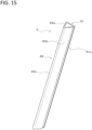
- FIG. 15 is a perspective view illustrating a yarn threading unit 6 according to the first modification.
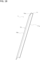
- FIG. 16 is a side view of the yarn threading unit 6.
- FIG. 17 is a perspective view illustrating a state where a yarn threading unit 6 is attached to a thermal insulation box 30 of a yarn drawing device 3 of a combined yarn producing device 1.
- the yarn threading unit 6 according to the first modification is used in the combined yarn producing device 1 illustrated in FIG. 1 .
- the combined yarn producing device according to the first modification is formed as a device that includes the combined yarn producing device 1 illustrated in FIG. 1 and the yarn threading unit 6 illustrated in FIG. 15 and FIG. 16 .
- the yarn threading unit 6 includes an attachment portion 61 and a yarn threading portion 62.
- the attachment portion 61 is formed as a portion that is detachably attached with respect to the box body 38 of the thermal insulation box 30.
- the attachment portion 61 includes a base portion 61a and a plurality of (two in this embodiment) hook portions 61b.
- the base portion 61a is formed as a portion extending in an elongated plate shape.
- the base portion 61a is formed such that a longitudinal direction of the base portion 61a extends in a straight line shape.
- Two respective hook portions 61b are formed as portions that engage with the right-side side wall 38b of the box body 38 when the attachment portion 61 is attached to the box body 38.
- the hook portion 61b is formed to have substantially the same configuration as the hook portion 51b of the yarn threading unit 5 of the first embodiment.
- the hook portion 61b is integrally formed with the base portion 61a and is formed in a protruding manner from the base portion 61a in a direction perpendicular to the longitudinal direction of the base portion 61a.
- An engaging pawl 61c that extends in a bending manner in a hook shape and engages with the locking groove 38c formed in the side wall 38b of the box body 38 is formed on a distal end side of the hook portion 61b.
- the respective hook portions 61b are inserted into the respective locking grooves 38c formed in the box body 38, and the position of the attachment portion 61 is manipulated such that the engaging pawls 61c of the respective hook portions 61b engage with the stepped portions in the respective locking grooves 38c. Due to the engagement between the engaging pawls 61c of the hook portions 61b and the locking grooves 38c, the attachment portion 61 is brought into a state where the attachment portion 61 is attached to the box body 38 and is held on the box body 38. In this modification, the mode is exemplified where the attachment portion 61 is attached to the box body 38 by making the hook portions 61b engage with the locking grooves 38c.
- the engagement mode is not limited to such a configuration. It is sufficient that the attachment portion 61 is detachably attached with respect to the box body 38.
- other grooves different from the locking grooves 38c may be formed on the side wall 38b of the box body 38, and the attachment portion 61 may be detachably attached with respect to the box body 38 by making the hook portions 61b engage with other grooves formed on the side wall 38b.
- the yarn threading portion 62 is formed as a portion that threads the second group of yarns Y2 in a state where the attachment portion 61 is attached to the box body 38, and the second group of yarns Y2 are threaded when the yarn threading operation using the yarn threading unit 6 is performed. Then, as illustrated in FIG.
- the yarn threading portion 62 is, in a state where the attachment portion 61 is attached to the box body 38, arranged so as to extend along an edge portion of the side wall 38b of the box body 38 closer to the guide rollers 36, 37 than the plurality of godet rollers 31 to 35 and along the edge portion of the side wall 38b of the box body 38 positioned between the plurality of godet rollers 31 to 35 and the guide rollers 36, 37.
- the yarn threading portion 62 is, in a state where the attachment portion 61 is attached to the box body 38, arranged so as to extend along the edge portion of the side wall 38b of the box body 38 at a position protruding toward more outside the box body 38 than the plurality of godet rollers 31 to 35, the position also being a position protruding from end face portions of the plurality of godet rollers 31 to 35 in the axial direction of the godet rollers 31 to 35.
- the yarn threading portion 62 specifically, includes a flat plate portion 62a and a flat plate portion 62b that are formed by bending a plate-shaped member integrally formed with the base portion 61a of the attachment portion 61.
- the flat plate portion 62a and the flat plate portion 62b are formed as portions having a flat plate shape extending parallel to the longitudinal direction of the base portion 61a.
- One end of both edge portions extending in the longitudinal direction of the flat plate portion 62a is integrally joined to the base portion 61a.
- the other end of both edge portions of the flat plate portion 62a extending in the longitudinal direction is integrally joined to the flat plate portion 62b.
- the base portion 61a, the flat plate portion 62a and the flat plate portion 62b are integrally formed so as to have an isosceles triangular cross-sectional shape where, in a cross section perpendicular to the longitudinal direction of the base portion 61a and the yarn threading portion 62, a portion that forms the flat plate portion 62a and a portion that forms the flat plate portion 62b form isosceles using a portion that forms the base portion 61a as a bottom side.
- the yarn threading portion 62 that is formed including the flat plate portion 62a and the flat plate portion 62b is formed by bending a plate-shaped member which becomes a material for the base portion 61a and the yarn threading portion 62 into a triangular columnar shape.
- Both the flat plate portion 62a and the flat plate portion 62b are, in a state where the attachment portion 61 is attached to the box body 38, formed so as to extend in a flat plate shape in the vertical direction along the edge portion of the side wall 38b of the box body 38 closer to the guide rollers 36, 37 than the plurality of godet rollers 31 to 35 and along the edge portion on a front side of the side wall 38a of the box body 38 positioned between the plurality of godet rollers 31 to 35 and the guide rollers 36, 37.
- both the flat plate portion 62a and the flat plate portion 62b are, in a state where the attachment portion 61 is attached to the box body 38, arranged so as to extend over from a position that corresponds to a height position of a portion of the godet roller 34 that forms an upper half portion to the position corresponding to a height position of a lower half portion of the godet roller 31 in the vertical direction.
- the yarn threading portion 62 that is formed such that the flat plate portion 62a and the flat plate portion 62b are integrally formed with each other includes a peak portion 62c that is formed as a joining portion between the flat plate portion 62a and the flat plate portion 62b.
- the second group of yarns Y2 are threaded through the yarn threading portion 62 at the peak portion 62c.
- the peak portion 62c of the yarn threading portion 62 forms, in a cross section perpendicular to the longitudinal direction of the base portion 61a and the yarn threading portion 62, a peak point portion in an isosceles triangular cross-sectional shape having a portion that forms the base portion 61a as a bottom side and a portion of the flat plate portion 62a and a portion of the flat plate portion 62b as two isosceles.
- the peak portion 62c is arranged on a side opposite to a hook portion 61b with respect to the base portion 61a.
- the peak portion 62c is arranged so as to extend along the vertical direction parallel to the edge portion of the side wall 38b at a position spaced apart from the edge portion of the side wall 38b of the box body 38. Accordingly, at a peak portion 62c, the yarn threading portion 62 is formed so as to extend parallel to the longitudinal direction of the base portion 51a in a spaced-apart manner from a base portion 61a by a distance corresponding to a height of an isosceles triangle where the portion that forms the flat plate portion 62a and the portion that forms the flat plate portion 62b form two isosceles.
- the peak portion 62c of the yarn threading portion 62 extends in a straight line shape at a position spaced apart from the base portion 51a of the attachment portion 51. Accordingly, in a state where the attachment portion 51 is attached to the box body 38, the peak portion 62c extends along the edge portion of the box body 38 at a position protruding more than the end face portions of the plurality of godet rollers 31 to 35 in the axial direction of the godet rollers 31 to 35.
- the yarn threading unit 6 is used in the same manner as the above-mentioned yarn threading unit 5.
- the yarn threading unit 6 is attached to the box body 38 of the thermal insulation box 30.
- the peak portion 62c of the yarn threading portion 62 of the yarn threading unit 6 is arranged so as to extend along the edge portion of the side wall 38b of the box body 38 at a position protruding more than the end face portions of the plurality of godet rollers 31 to 35 in the axial direction of the godet rollers 31 to 35. Then, in such a state, the yarn threading operation is performed.
- the operator manipulates the suction gun 100 so that the suction gun 100 suctions the plurality of yarns Y supplied from the spinning device 2 and divides the plurality of yarns Y into the first group of yarns Y1 and the second group of yarns Y2. With respect to the divided second group of yarns Y2, the second group of yarns Y2 are wound onto the guide roller 36 arranged on a yarn threading unit 6 side with respect to the plurality of godet rollers 31 to 35.
- the operator holds the suction gun 100 for suctioning the plurality of yarns Y with both hands, and sequentially performs the operations of winding the first group of yarns Y1 onto the plurality of godet rollers 31 to 35 by manipulating the position of the suction gun 100.
- the second group of yarns Y2 that are wound onto the guide roller 36 and are suctioned by the suction gun 100 are, in a yarn path from the guide roller 36 to the suction opening 100a of the suction gun 100, threaded through the yarn threading portion 62 of the yarn threading unit 6 extending along the edge portion of the box body 38 at the position protruding toward more outside of the box body 38 than the plurality of godet rollers 31 to 35, the position also being a position protruding more than the end face portions of the godet rollers 31 to 35 in the axial direction of the godet rollers 31 to 35.
- a state is maintained where a yarn path of the second group of yarns Y2 takes a roundabout route with respect to the position that protrudes more outside of the box body 38 than the plurality of godet rollers 31 to 35, the position also being a position protruding more than the end face portions of the godet rollers 31 to 35 in the axial direction of the godet rollers 31 to 35 at a part of the portion positioned between the guide roller 36 in a yarn path of the second group of yarns Y2 and the suction gun 100.
- the operator can easily perform the yarn threading operation for sequentially winding the first group of yarns Y1 onto the plurality of godet rollers 31 to 35 while maintaining a state where a yarn path of the first group of yarns Y1 and a yarn path of the second group of yarns Y2 are divided from each other by manipulating the heavy suction gun 100 with both hands.
- the yarn threading operation can be performed easily, an operation time necessary for the yarn threading operation can be largely shortened.
- the operation time of the yarn threading operation can be largely shortened, a quantity of yarns suctioned into the suction gun 100 during the operation can be reduced and hence, the generated yarn waste can be largely reduced.
- the first modification can provide the yarn threading unit 6 and the combined yarn producing device equipped with the yarn threading unit 6 where, the yarn threading operation for sequentially winding the first group of yarns Y1 on the plurality of godet rollers 31 to 35 can be performed easily by manipulating the suction gun 100 with both hands. Further, the operation time necessary for the yarn threading operation can be largely shortened and, at the same time, a quantity of yarns suctioned into the suction gun 100 can be reduced thus largely reducing the generation of the yarn waste.
- the yarn threading unit 6 can be easily formed with the simple structure that includes: the yarn threading portion 62 having the flat plate portion 62a and the flat plate portion 62b that extend in a straight line shape; and the attachment portion 61 for attaching the yarn threading unit 6 to the box body 38. That is, the yarn threading unit 6 that allows the operator to easily perform the yarn threading operation for winding the first group of yarns Y1 onto the plurality of godet rollers 31 to 35 while maintaining a state where a yarn path of the first group of yarns Y1 and a yarn path of the second group of yarns Y2 are divided from each other by manipulating the suction gun 100 with both hands can be easily formed with the simple structure.
- FIG. 18 is a perspective view illustrating a yarn threading unit 7 according to the second modification.
- FIG. 19 is a side view of the yarn threading unit 7.
- FIG. 20 is a perspective view illustrating a state where the yarn threading unit 7 is attached to the thermal insulation box 30 of the yarn drawing device 3 of the combined yarn producing device 1.
- the yarn threading unit 7 according to the second modification is used in the combined yarn producing device 1 illustrated in FIG. 1 .
- the combined yarn producing device according to the second modification is formed as a device that includes the combined yarn producing device 1 illustrated in FIG. 1 and the yarn threading unit 7 illustrated in FIG. 18 and FIG. 19 .
- the yarn threading unit 7 includes an attachment portion 71 and a yarn threading portion 72.
- the attachment portion 71 is formed as a portion that is detachably attached with respect to the box body 38 of the thermal insulation box 30.
- the attachment portion 71 includes a base portion 71a and a plurality of (two in this embodiment) hook portions 71b.
- the base portion 71a is formed as a portion extending in an elongated plate shape.
- the base portion 71a is formed such that a longitudinal direction of the base portion 71a extends in a straight line shape.
- Two respective hook portions 71b are formed as portions that engage with the right-side side wall 38b of the box body 38 when the attachment portion 71 is attached to the box body 38.
- the hook portion 71b is formed to have substantially the same configuration as the hook portion 51b of the yarn threading unit 5 of the first embodiment.
- the hook portion 71b is integrally formed with the base portion 71a and is formed in a protruding manner from the base portion 71a in a direction perpendicular to the longitudinal direction of the base portion 71a.
- An engaging pawl 71c that extends in a bending manner in a hook shape and engages with the locking groove 38c formed in the side wall 38b of the box body 38 is formed on a distal end side of the hook portion 71b.
- the respective hook portions 71b are inserted into the respective locking grooves 38c formed in the box body 38, and the position of the attachment portion 71 is manipulated such that the engaging pawls 71c of the respective hook portions 71b engage with the stepped portions in the respective locking grooves 38c. Due to the engagement between the engaging pawls 71c of the hook portions 71b and the locking grooves 38c, the attachment portion 71 is brought into a state where the attachment portion 71 is attached to the box body 38 and is held on the box body 38. In this modification, the mode is exemplified where the attachment portion 71 is attached to the box body 38 by making the hook portions 71b engage with the locking grooves 38c.
- the engagement mode is not limited to such a configuration. It is sufficient that the attachment portion 71 is detachably attached with respect to the box body 38.
- other grooves different from the locking grooves 38c may be formed on the side wall 38b of the box body 38, and the attachment portion 71 may be detachably attached with respect to the box body 38 by making the hook portions 71b engage with other grooves formed on the side wall 38b.
- the yarn threading portion 72 is formed as a portion that threads the second group of yarns Y2 in a state where the attachment portion 71 is attached to the box body 38, and the second group of yarns Y2 are threaded when the yarn threading operation using the yarn threading unit 7 is performed. Then, as illustrated in FIG. 20 , the yarn threading portion 72 is, in a state where the attachment portion 71 is attached to the box body 38, arranged so as to extend along an edge portion of the side wall 38b of the box body 38 closer to the guide rollers 36, 37 than the plurality of godet rollers 31 to 35 and along the edge portion of the side wall 38b of the box body 38 positioned between the plurality of godet rollers 31 to 35 and the guide rollers 36, 37.
- the yarn threading portion 72 is, in a state where the attachment portion 71 is attached to the box body 38, arranged so as to extend along the edge portion of the side wall 38b of the box body 38 at a position protruding toward more outside the box body 38 than the plurality of godet rollers 31 to 35, the position also being a position protruding from end face portions of the plurality of godet rollers 31 to 35 in the axial direction of the godet rollers 31 to 35.
- the yarn threading portion 72 specifically, includes a flat plate portion 72a that is formed by bending a plate-shaped member that is integrally formed with a base portion 71a of the attachment portion 71.
- the flat plate portion 72a is formed as a flat-plate-shaped portion that extends parallel to the longitudinal direction of the base portion 71a.
- One of both edge portions of the flat plate portion 72a extending in the longitudinal direction is integrally joined to the base portion 71a.
- the base portion 71a and the flat plate portion 72a are integrally formed with each other such that, in a cross section perpendicular to the longitudinal direction of the base portion 71a and the flat plate portion 72a, a portion of the base portion 71a and a portion of the flat plate portion 72a intersect orthogonally with each other so as to form an L-shaped cross section in a cross section perpendicular to the base portion 71a and the flat plate portion 72a.
- the yarn threading portion 72 formed by including the flat plate portion 72a is formed, for example, by bending a plate-shaped member which becomes a material for forming the base portion 71a and the yarn threading portion 72 so as to form an L-shaped cross section.
- the flat plate portion 72a is, in a state where the attachment portion 71 is attached to the box body 38, formed so as to extend in a flat plate shape in the vertical direction along the edge portion of a front side of the side wall 38a of the box body 38 on a guide roller 36, 37 side with respect to the plurality of godet rollers 31 to 35 at a position between the plurality of godet rollers 31 to 35 and the guide roller 36, 37.
- the flat plate portion 72a is, in a state where the attachment portion 71 is attached to the box body 38, arranged so as to extend over from a position that corresponds to a height position of a portion of the godet roller 34 that forms an upper half to the position corresponding to a height position of a lower half of the godet roller 31.
- the yarn threading portion 72 that is formed by including the flat plate portion 72a that is integrally joined to the base portion 71a has the edge portion 72b that extends along the longitudinal direction of the yarn threading portion 72 at an end portion of the flat plate portion 72a on a side opposite to an end portion of the flat plate portion 72a on a side where the end portion is integrally joined to the base portion 71a.
- the second group of yarns Y2 are threaded through the yarn threading portion 72 at the edge portion 72b.
- the edge portion 72b is arranged on a side opposite to the hook portion 71b with respect to the base portion 71a.
- the edge portion 72b is, in a state where the attachment portion 71 is attached to the box body 38, arranged so as to extend in the vertical direction parallel to the edge portion of the side wall 38b at a position spaced apart from the edge portion of the side wall 38b of the box body 38. Accordingly, the yarn threading portion 72 is formed so as to extend parallel to the longitudinal direction of the base portion 71a in a state where the edge portion 72b is spaced apart from the base portion 71a by a distance corresponding to a protruding amount of the flat plate portion 72a that protrudes in an L shape with respect to the base portion 71a.
- edge portion 72b of the yarn threading portion 72 extends in a straight line shape at the position spaced apart from the base portion 71a of the attachment portion 71. Accordingly, in a state where the attachment portion 71 is attached to the box body 38, the edge portion 72b of the yarn threading portion 72 extends along the edge portion of the box body 38 at a position protruding more than the end face portions of the plurality of godet rollers 31 to 35 in the axial direction of the godet rollers 31 to 35.
- the yarn threading unit 7 is used in the same manner as the above-mentioned yarn threading unit 5.
- the yarn threading unit 7 is attached to the box body 38 of the thermal insulation box 30.
- the edge portion 72b of the yarn threading portion 72 of the yarn threading unit 7 is arranged so as to extend along the edge portion of the side wall 38b of the box body 38 at a position protruding more than the end face portions of the plurality of godet rollers 31 to 35 in the axial direction of the godet rollers 31 to 35. Then, in such a state, the yarn threading operation is performed.
- the operator manipulates the suction gun 100 so that the suction gun 100 suctions the plurality of yarns Y supplied from the spinning device 2 and divides the plurality of yarns Y into the first group of yarns Y1 and the second group of yarns Y2. With respect to the divided second group of yarns Y2, the second group of yarns Y2 are wound onto the guide roller 36 arranged on a yarn threading unit 7 side with respect to the plurality of godet rollers 31 to 35.
- the operator holds the suction gun 100 for suctioning the plurality of yarns Y with both hands, and sequentially performs the operations of winding the first group of yarns Y1 onto the plurality of godet rollers 31 to 35 by manipulating the position of the suction gun 100.
- the second group of yarns Y2 that are wound onto the guide roller 36 and are suctioned by the suction gun 100 are, in a yarn path from the guide roller 36 to the suction opening 100a of the suction gun 100, threaded through the yarn threading portion 72 of the yarn threading unit 7 extending along the edge portion of the box body 38 at the position protruding toward more outside of the box body 38 than the plurality of godet rollers 31 to 35, the position also being a position protruding more than the end face portions of the godet rollers 31 to 35 in the axial direction of the godet rollers 31 to 35.
- a state is maintained where a yarn path of the second group of yarns Y2 takes a roundabout route with respect to the position that protrudes more outside of the box body 38 than the plurality of godet rollers 31 to 35 also being a position protruding more than the end face portions of the godet rollers 31 to 35 in the axial direction of the godet rollers 31 to 35 at a part of the portion positioned between the guide roller 36 in a yarn path of the second group of yarns Y2 and the suction gun 100.
- the operator can easily perform the yarn threading operation for sequentially winding the first group of yarns Y1 onto the plurality of godet rollers 31 to 35 while maintaining a state where a yarn path of the first group of yarns Y1 and a yarn path of the second group of yarns Y2 are divided from each other by manipulating the heavy suction gun 100 with both hands.
- the yarn threading operation can be performed easily, an operation time necessary for the yarn threading operation can be largely shortened.
- the operation time of the yarn threading operation can be largely shortened, a quantity of yarns suctioned into the suction gun 100 during the operation can be reduced and hence, the generated yarn waste can be largely reduced.
- the second modification can provide the yarn threading unit 7 and the combined yarn producing device equipped with the yarn threading unit 7 where, the yarn threading operation for sequentially winding the first group of yarns Y1 on the plurality of godet rollers 31 to 35 can be performed easily by manipulating the suction gun 100 with both hands. Further, the operation time necessary for the yarn threading operation can be largely shortened and, at the same time, a quantity of yarns suctioned into the suction gun 100 can be reduced thus largely reducing the generation of the yarn waste.
- the yarn threading unit 7 can be easily formed with the simple structure that includes: the yarn threading portion 72 having the flat plate portion 72a that extends in a straight line shape: and the attachment portion 71 for attaching the yarn threading unit 7 to the box body 38. That is, the yarn threading unit 7 that allows the operator to easily perform the yarn threading operation for winding the first group of yarns Y1 onto the plurality of godet rollers 31 to 35 while maintaining a state where a yarn path of the first group of yarns Y1 and a yarn path of the second group of yarns Y2 are divided from each other by manipulating the suction gun 100 with both hands can be easily formed with the simple structure.
- FIG. 21 is a perspective view illustrating a state where a yarn threading unit 8 according to the third modification is attached to the thermal insulation box 30 of the yarn drawing device 3 of the combined yarn producing device 1.
- the yarn threading unit 8 according to the third modification is used in the combined yarn producing device 1 illustrated in FIG. 1 .
- the combined yarn producing device according to the third modification is formed as a device that includes the combined yarn producing device 1 illustrated in FIG. 1 and the yarn threading unit 8 illustrated in FIG. 21 .
- the configuration of the yarn threading unit 8 that differs from the corresponding yarn threading unit in the above-mentioned first embodiment is described. With respect to the configurations substantially equal to the corresponding configurations of the first embodiment, same symbols are given in the drawing or the same symbols are quoted and the repeated description is omitted.
- the yarn threading unit 8 is formed as a flat-plate-shaped member that is attached to the box body 38 of the thermal insulation box 30.
- the yarn threading unit 8 is formed of an attachment portion 81 and a yarn threading portion 82.
- the attachment portion 81 is provided as a portion that is attached to and fixed to the right-side side wall 38a of the box body 38 of the thermal insulation box 30.
- the attachment portion 81 is fixed to and attached to the side wall 38a of the box body 38 outside the side wall 38a in a state where the attachment portion 81 overlaps with the surface of the side wall 38a.
- the attachment portion 81 is fixedly attached to the box body 38, for example, by joining the attachment portion 81 to the side wall 38a using a fastening jig such as bolts or by welding the attachment portion 81 to the side wall 38a of the box body 38.
- the yarn threading portion 82 is integrally formed with the attachment portion 81.
- the yarn threading portion 82 is formed as a portion that protrudes forward from the attachment portion 81 that is attached to the side wall 38a of the box body 38.
- the yarn threading portion 82 is formed as a portion by which the second group of yarns Y2 are threaded at the time of performing a yarn threading operation using the yarn threading unit 8. As illustrated in FIG.
- the yarn threading portion 82 is formed in an extending manner in a flat plate shape in the vertical direction along the edge portion of the side wall 38b of the box body 38 more closer to the guide rollers 36, 37 than the plurality of godet rollers 31 to 35, that is, along the edge portion of the side wall 38b of the box body 38 between the plurality of godet rollers 31 to 35 and the guide rollers 36, 37. Further, the yarn threading portion 82 is arranged so as to vertically extend over from a position that corresponds to a height position of a portion of the godet roller 34 that forms an upper half portion to the position corresponding to a height position of a lower half portion of the godet roller 31.
- the yarn threading portion 82 is formed so as to extend along the edge portion of the side wall 38b of the box body 38 at a position that protrudes more outside of the box body 38 than the plurality of godet rollers 31 to 35, the position also being a position that protrudes more than the end face portions of the plurality of godet rollers 31 to 35 in the axial direction of the godet rollers 31 to 35.
- an edge portion 82a that extends along the longitudinal direction of the yarn threading portion 82 is formed.
- the second group of yarns Y2 are threaded through the yarn threading portion 82 at the edge portion 82a.
- the yarn threading portion 82 protrudes forward than the edge portion of the side wall 38b of the box body 38.
- the edge portion 82a of the yarn threading portion 82 is arranged so as to extend in the vertical direction parallel to the edge portion of the side wall 38b at the position that protrudes more forward than the edge portion of the side wall 38b of the box body 38. Further, the edge portion 82b of the yarn threading portion 82 is formed so as to extend along the edge portion of the box body 38 at the position that protrudes more than the end face portions of the plurality of godet rollers 31 to 35 in the axis direction of the godet rollers 31 to 35.
- the above-mentioned yarn threading unit 8 is always attached to the box body 38 of the thermal insulation box 30.
- the yarn threading unit 8 is used in a state where the yarn threading unit 8 is kept attached to the box body 38.
- the operator manipulates the suction gun 100 so that the suction gun 100 suctions the plurality of yarns Y supplied from the spinning device 2 and divides the plurality of yarns Y into the first group of yarns Y1 and the second group of yarns Y2.
- the second group of yarns Y2 are wound onto the guide roller 36 arranged at a position closer to the yarn threading unit 8 than the plurality of godet rollers 31 to 35. Then, the operator holds the suction gun 100 for suctioning the plurality of yarns Y with both hands, and sequentially performs the operations of winding the first group of yarns Y1 onto the plurality of godet rollers 31 to 35 by manipulating the position of the suction gun 100.
- the second group of yarns Y2 that are wound onto the guide roller 36 and are suctioned by the suction gun 100 are, in a yarn path from the guide roller 36 to the suction opening 100a of the suction gun 100, threaded through the yarn threading portion 82 of the yarn threading unit 8 extending along the edge portion of the box body 38 at the position protruding toward more outside of the box body 38 than the plurality of godet rollers 31 to 35, the position also being a position protruding more than the end face portions of the godet rollers 31 to 35 in the axial direction of the godet rollers 31 to 35.
- a state is maintained where a yarn path of the second group of yarns Y2 takes a roundabout route with respect to the position that protrudes more outside of the box body 38 than the plurality of godet rollers 31 to 35, the position also being a position protruding from the end face portions of the godet rollers 31 to 35 in the axial direction of the godet rollers 31 to 35 between the guide roller 36 in a yarn path of the second group of yarns Y2 and the suction gun 100.
- the operator can easily perform the yarn threading operation for sequentially winding the first group of yarns Y1 onto the plurality of godet rollers 31 to 35 while maintaining a state where a yarn path of the first group of yarns Y1 and a yarn path of the second group of yarns Y2 are divided from each other by manipulating the heavy suction gun 100 with both hands.
- the yarn threading operation can be performed easily, an operation time necessary for the yarn threading operation can be largely shortened.
- the operation time of the yarn threading operation can be largely shortened, a quantity of yarns suctioned into the suction gun 100 during the operation can be reduced and hence, the generated yarn waste can be largely reduced.
- the third modification can provide the yarn threading unit 8 and the combined yarn producing device equipped with the yarn threading unit 8 where, the yarn threading operation for sequentially winding the first group of yarns Y1 onto the plurality of godet rollers 31 to 35 can be performed easily by manipulating the suction gun 100 with both hands. Further, the operation time necessary for the yarn threading operation can be largely shortened and, at the same time, a quantity of yarns suctioned into the suction gun 100 can be reduced thus largely reducing the generation of the yarn waste.
- FIG. 22 is a view illustrating a combined yarn producing device 1A in which a yarn threading unit 5A (see FIG. 25 ) according to the second embodiment of the present invention is used and a combined yarn producing device according to the second embodiment of the present invention.
- FIG. 22 is also a front view illustrating the combined yarn producing device 1A that produces a bi-shrinkage yarn by applying a heat set (heat treatment) to partially oriented yarns.
- FIG. 23 is a front view illustrating a yarn drawing device 3A in the combined yarn producing device 1A illustrated in FIG. 22 .
- FIG. 24 is a perspective view of the yarn drawing device 3A illustrated in FIG. 23 .
- FIG. 25 is a perspective view illustrating the yarn threading unit 5A according to the second embodiment of the present invention.
- the configurations of the yarn drawing device 3A and the yarn threading unit 5A that differs from the corresponding configurations of the yarn drawing device and the corresponding yarn threading unit in the above-mentioned first embodiment is described.
- same symbols are given in the drawing or the same symbols are quoted and the repeated description is omitted.
- the yarn drawing device 3A includes a thermal insulation box 30A, a plurality of (five in this embodiment) godet rollers 31 to 35 having a heat source, a guide roller 36A, and a doubling assist device 17.
- the yarn drawing device 3A has substantially the same configuration as the yarn drawing device 3 of the first embodiment, the yarn drawing device 3A differs from the yarn drawing device 3 with respect to a point that a heat set is applied to the second group of yarns Y2 by the godet rollers 34, 35 in a partially oriented yarn state.
- the first group of yarns Y1 are indicated by a chained line
- the second group of yarns Y2 are indicated by a double-dashed chained line
- the bi-shrinkage yarns Y3 are indicated by a solid line.
- the thermal insulation box 30A of the yarn drawing device 3A has substantially the same configuration as the thermal insulation box 30 of the yarn drawing device 3 according to the first embodiment. That is, the thermal insulation box 30A has a box body 38 that accommodated a plurality of godet rollers 31 to 35, a door 39 that opens and closes the box body 38. However, the thermal insulation box 30A differs from the thermal insulation box 30 according to the first embodiment with respect to the following point.
- the thermal insulation box 30A further includes, in the box body 38, in addition to an inlet port 30a for introducing the first group of yarns Y1 into the inside of the box body 38, an inlet port 30c for introducing the second group of yarns Y2 into the inside of the box body 38.
- the inlet port 30c is formed in an upper half side of a side wall 38b of the box body 38 on a right side.
- the inlet port 30c is positioned between the inlet port 30a and the outlet port 30b, and is provided as an inlet for the second group of yarns Y2.
- the guide roller 36A is arranged in the inlet port 30c.
- the guide roller 36A is provided as a guide roller for guiding the second group of yarns Y2 that is divided from a plurality of yarns Y as the yarns Y2 other than the first group of yarns Y1.
- two guide rollers 36, 37 are provided for guiding the second group of yarns Y2.
- one guide roller 36A is provided in the yarn drawing device 3A according to the second embodiment.
- the guide roller 36A is formed as a rotatable roller having a rotary shaft extending in the longitudinal direction.
- the guide roller 36A is arranged in the side wall 38b spaced apart from the plurality of godet rollers 31 to 33. More specifically, the guide roller 36A is arranged in the inlet port 30c formed in the side wall 38b.
- the guide roller 36A has an outer diameter larger than a thickness of the side wall 38b of the box body 38 of the thermal insulation box 30A. With such a configuration, as viewed from an axis direction, the guide roller 36A is arranged in a protruding manner from the side wall 38b of the box body 38 of the thermal insulation box 30A toward the outside and the inside of the thermal insulation box 30A.
- the guide roller 36A be formed as a drive roller that is rotatably driven by an electrically-operated motor not illustrated in the drawing.
- the guide roller 36A may be formed as a driven roller that rotates due to a friction of the second group of yarns Y2.
- the yarn drawing device 3A includes a doubling assist device 17.
- the doubling assist device 17 is arranged in the thermal insulation box 30A.
- the doubling assist device 17 is arranged between the position at which the yarn Y is separated from the godet roller 35 on a most downstream side in the yarn traveling direction and the position also being a position at which the yarn Y is discharged from the thermal insulation box 30A.
- the doubling assist device 17 is an entangling device that ejects compressed air and doubles the first group of yarns Y1 and the second group of yarns Y2 to each other due to an action of compressed air.
- an air ejection pressure of the yarn doubling assist device 17 is set lower than an air ejection pressure of the yarn doubling device 16. Accordingly, the degree of doubling the first group of yarns Y1 and the second group of yarns Y2 by the doubling assist device 17 is weaker than the degree of doubling the first group of yarns Y1 and the second group of yarns Y2 by the yarn doubling device 16.
- the doubling assist device 17 plays a role of assisting the yarn doubling device 16.
- the first group of yarns Y1 are introduced into the thermal insulation box 30 from the inlet port 30a via the yarn feed roller 12.
- the first group of yarns Y1 are threaded onto the godet rollers 31 to 33 that form preheating rollers, the godet rollers 34, 35 that form heat set rollers, and the doubling assist device 17.
- the first group of yarns Y1 are threaded onto and travel on the godet roller 31, the godet roller 32, the godet roller 33, the godet roller 34, the godet roller 35, and the doubling assist device 17 in this order.
- the first group of yarns Y1 are preheated to a temperature that enables drawing of the first group of yarns Y1 (a temperature equal to or above a glass transition point) by the godet rollers 31 to 33 that form the preheating rollers.
- the preheated first group of yarns Y1 are formed into drawn yarns due to a difference in yarn feed speed between the godet roller 33 and the godet roller 34. Further, heat set is applied to the first group of yarns Y1 in a drawn state by the godet rollers 34, 35.
- the second group of yarns Y2 are introduced into the thermal insulation box 30A from the inlet port 30c via the guide rollers 36A, and threaded onto the godet rollers 34,35 and the doubling assist device 37.
- the second group of yarns Y2 are introduced to the godet roller 34 arranged adjacently to the side wall 38b of the thermal insulation box 30A on a right side from the guide roller 36A. That is, the second group of yarns Y2 do not pass the godet rollers 31 to 33 that are preheating rollers, and reach the godet roller 34 that is a heat set roller.
- the second group of yarns Y2 are wound onto the godet rollers 34, 35 without passing the godet rollers 31 to 33 and hence, the second group of yarns Y2 are heat set in a partially oriented yarn state by the godet rollers 34, 35.
- the first group of yarns Y1 and the second group of yarns Y2 that are doubled by the godet roller 34 are doubled by the doubling assist device 37 so that the bi-shrinkage yarns Y3 are formed.
- the bi-shrinkage yarns Y3 are discharged to the outside of the thermal insulation box 30A from the outlet port 30b, and are wound onto by the winding device 4 via the yarn feed rollers 13 to 15. Between the yarn feed roller 13 and the yarn feed roller 14, the doubling of the bi-shrinkage yarns Y3 is performed again by the yarn doubling device 16.
- FIG.25 is a perspective view illustrating the yarn threading unit 5A according to the second embodiment of the present invention.
- FIG. 26 is a front view illustrating a state where the yarn threading unit 5A is attached to the thermal insulation box 30A of the yarn drawing device 3A of the combined yarn producing device 1.
- FIG. 26 illustrates a state where the door 39 of the thermal insulation box 30A is opened.
- the yarn threading unit 5A is described with reference to FIG. 25 and FIG. 26 .
- the yarn threading unit 5A is used in the combined yarn producing device 1A that produces the bi-shrinkage yarns Y3 by doubling the first group of yarns Y1 and the second group of yarns Y2.
- the yarn threading unit 5A is used in performing a yarn threading operation where the first group of yarns Y1 are wound onto the plurality of godet rollers 31 to 33 that form the preheating rollers while winding the second group of yarns Y2 onto the guide roller 36A.
- the yarn threading unit 5A includes, in the same manner as the yarn threading unit 5 of the first embodiment, an attachment portion 51 and a yarn threading portion 52. However, the yarn threading unit 5A is set shorter compared to the yarn threading unit 5 of the first embodiment with respect to a length in the longitudinal direction. That is, A length of the attachment portion 51 and a length of the yarn threading portion 52 in the yarn threading unit 5A are set shorter than a length of the attachment portion 51 and a length of the yarn threading portion 52 in the yarn threading unit 5 in the first embodiment.
- the yarn threading unit 5A is configured to correspond to a yarn threading operation where the first group of yarns Y1 are wound onto the plurality of godet rollers 31 to 33 that are preheating rollers while winding the second group of yarns Y2 onto the guide roller 36A.
- the attachment portion 51 of the yarn threading unit 5A is formed as a portion that is detachably attached with respect to the box body 38 of the thermal insulation box 30A in the yarn threading unit 5A.
- the attachment portion 51 includes a base portion 51a and a plurality of (two in the second embodiment) hook portions 51b.
- the base portion 51a is provided as a member extending in an elongated plate shape, and is formed such that a longitudinal direction of the base portion 51a extends in a straight line shape. In attaching the attachment portion 51 to the box body 38, the base portion 51a is arranged in a state where that the base portion 51a extends along an edge portion of the side wall 38b of the box body 38 on a right side.
- the base portion 51a of the yarn threading unit 5A is formed with a length in the longitudinal direction shorter than a length of the base portion 51 of the yarn threading unit 5 of the first embodiment in the longitudinal direction.
- the length of the attachment portion 51 is set corresponding to a length of the edge portion of the side wall 38b from the inlet port 30a to the inlet port 30c of the thermal insulation box 30A.
- Hook portions 51b of the attachment portion 51 of the yarn threading unit 5A are formed substantially in the same manner as the hook portions 51b of the attachment portion 51 of the yarn threading unit 5 according to the first embodiment.
- Each hook portion 51b includes a pawl portion 51c that engages with each of locking grooves 38c formed on the side wall 38b of the box body 38 of the thermal insulation box 30A. When the attachment portion 51b is attached to the box body 38, each hook portion 51b is inserted into each locking groove 38c formed on the side wall 38b of the box body 38.
- the engaging pawl 51c arranged on the distal end side of each hook portion 51b engages with a stepped portion in each locking groove 38c. Due to the engagement between the engaging pawl 51c of the hook portion 51b and the stepped portion in the locking groove 38c, the attachment portion 51 is brought into a state where the attachment portion 51 is attached to the box body 38 and hence, the attachment portion 51 is held by the box body 38.
- the mode is exemplified where the attachment portion 51 is attached to the box body 38 due to the engagement between the hook portion 51b and the locking groove 38c.
- the attachment portion 51 may not be mounted in this manner, and it is sufficient that the attachment portion 51 may be detachably attached with respect to the box body 38.
- other grooves different from the locking grooves 38c may be formed on the side wall 38b of the box body 38, and the hook portions 51b may engage with the other grooves formed on the side wall 38b so that the attachment portion 51 may be detachably attached with respect to the box body 38.
- the yarn threading portion 52 of the yarn threading unit 5A is formed as a portion by which the second group of yarns Y2 are guided in a state where the attachment portion 51 is attached to the box body 38.
- the second group of yarns Y2 are guided when a yarn threading operation using the yarn threading unit 5A is performed.
- the yarn threading portion 52 is spaced apart from the plurality of godet rollers 31 to 33 that form the preheating rollers, and is arranged so as to extend along an edge portion of the side wall 38b of the box body 38 in which the guide roller 36A is arranged in a state where the attachment portion 51 is attached to the box body 38.
- the yarn threading portion 52 is arranged so as to extend along the edge portion of the side wall 38b of the box body 38 at a position protruding more outside of the box body 38 than the plurality of godet rollers 31 to 33 that form the preheating rollers, the position also being a position protruding from the end face portions of the plurality of godet rollers 31 to 33 in the axial direction of the godet rollers 31 to 33 in a state where the attachment portion 51 is attached to the box body 38.
- the yarn threading portion 52 includes a rod-shaped portion 52a and a pair of leg portions 52b.
- the rod-shaped portion 52a is formed as a rod-shaped portion that extends parallel to the longitudinal direction of the base portion 51a of the attachment portion 51.
- the rod-shaped portion 52a is spaced apart from the plurality of godet rollers 31 to 33 that form the preheating rollers, and is formed so as to extend in a straight line shape in the vertical direction along a front-side edge portion of the side wall 38a of the box body 38 on which the guide roller 36A is arranged.
- the rod-shaped portion 52a is formed so as to extend in the vertical direction over from a position corresponding to a height position of a portion of the godet roller 34 that forms a lower half portion of the godet roller 34 to a position corresponding to a height position of a portion of the godet roller 31 that forms a lower half portion of the godet roller 31.
- the pair of leg portions 52b of the yarn threading portion 52 of the yarn threading unit 5A is formed in the same manner as the pair of leg portions 52b of the yarn threading portion 52 of the yarn threading unit 5 according to the first embodiment.
- Each of the pair of leg portions 52b is formed so as to protrude toward a side opposite to a side from which the hook portion 51b protrudes with respect to the base portion 51a.
- One end portion of each leg portion 52b is fixed to the base portion 51a, and the other end portion of each leg portion 52b is integrally joined to the rod-shaped portion 52a thus supporting the rod-shaped portion 52a.
- the leg portions 52b protrude toward a front side in the horizontal direction with respect to the edge portion of the side wall 38b of the box body 38.
- the rod-shaped portion 52a is arranged so as to extend in the vertical direction parallel to the edge portion of the side wall 38b at the position spaced apart from the edge portion of the side wall 38b of the box body 38.
- the rod-shaped portion 52a of the yarn threading portion 52 of the yarn threading unit 5A is formed so as to extend parallel to the longitudinal direction of the base portion 51a in a state where the rod-shaped portion 52a is spaced apart from the base portion 51a of the attachment portion 51 by a distance corresponding to a length of the leg portion 52b.
- the rod-shaped portion 52a of the yarn threading portion 52 extends in a straight line shape at a position spaced apart from the base portion 51a of the attachment portion 51 by the length of the leg portion 52b and hence, in a state where the attachment portion 51 is attached to the box body 38 of the thermal insulation box 30, the rod-shaped portion 52a is formed so as to extend along the edge portion of the side wall 38b of the box body 38 at the position protruding more than the end face portions of the plurality of godet rollers 31 to 33 in the axial direction of the godet rollers 31 to 33.
- FIG. 27 to FIG. 33 are views illustrating a state where a yarn threading operation is performed using the yarn threading unit 5A in the combined yarn producing device 1A.
- a mode where the yarn threading operation is performed using the yarn threading unit 5A in the combined yarn producing device 1A is described with reference to FIG. 26 to FIG. 33 .
- the yarn threading operation is performed such that, first, prior to the production of the bi-shrinkage yarns Y3, the plurality of yarns Y supplied from the spinning device 2 are divided into the first group of yarns Y1 and the second group of yarns Y2, and the first group of yarns Y1 are wound onto the plurality of godet rollers 31 to 33 while winding the second group of yarns Y2 onto the guide roller 36A.
- the yarn threading operation as illustrated in FIG.
- the yarn threading unit 5A is attached to the box body 38 of the thermal insulation box 30A in a spaced-apart-manner from the plurality of godet rollers 31 to 33 and at the edge portion of the side wall 38b of the box body 38 on which the guide roller 36A is arranged.
- an operator who performs the yarn threading operation makes the hook portions 51b of the attachment portion 51 engage with the locking grooves 38c formed on the side wall 38b of the box body 38 thus attaching the yarn threading unit 5A to the box body 38.
- the yarn threading portion 52 of the yarn threading unit 5A is arranged so as to extend along the edge portion of the side wall 38b of the box body 38 at the position where the yarn threading portion 52 protrudes more than the end face portions of the plurality of godet rollers 31 to 33 in the axial direction of the godet rollers 31 to 33.
- FIG. 27 is a view illustrating a state where the first group of yarns Y1 are wound onto the yarn feed roller 12 outside the thermal insulation box 30, and the second group of yarns Y2 are wound onto the guide roller 36A.
- the operator makes the suction gun 100 suction the plurality of yarns Y supplied from the spinning device 2, and divides the plurality of yarns Y into the first group of yarns Y1 and the second group of yarns Y2.
- the operator When the plurality of yarns Y are divided into the first group of yarns Y1 and the second group of yarns Y2, the operator temporarily winds the plurality of yarns Y suctioned by the suction gun 100 onto the guide roller 36A. Then, the operator holds the suction gun with one hand, and holds an instrument for dividing yarns (not illustrated in the drawing) that can hook the yarns on a distal-end-side portion with the other hand. Using the instrument for dividing the yarns that the operator holds with the other hand, the operator performs an operation of dividing the plurality of supplied yarns into the first group of yarns Y1 and the second group of yarns Y2.
- the operator winds the first group of yarns Y1 onto the yarn feed roller 12 by manipulating the instrument for dividing yarns.
- the operator releases the instrument for dividing yarns from his hand, and holds the suction gun 100 with both hands.
- the operator manipulates the position of the suction gun 100 such that the suction opening 100a of the suction gun 100 moves an area between the godet roller 31 and the yarn threading portion 52 of the yarn threading unit 5A.
- the first group of yarns Y1 wound onto the yarn feed roller 12 pass through the inlet port 30a of the box body 38, and the second group of yarns Y2 wound onto the guide roller 36A pass on the rod-shaped portion 52a in a state where the second group of yarns Y2 are threaded onto an outer periphery of the rod-shaped portion 52a of the yarn threading portion 52.
- FIG. 28 is a view illustrating a state where the first group of yarns Y1 are wound onto the first godet roller 31 in the yarn traveling direction.
- the operator manipulates the position of the suction gun 100 in a state where the suction opening 100a of the suction gun 100 is inserted into the inside of the box body 38.
- the operator manipulates the suction gun 100 with both hands so as to move the suction opening 100a in a clockwise direction in FIG. 28 along an outer periphery of the godet roller 31.
- the first group of yarns Y1 are wound onto the godet roller 31 along the yarn traveling direction of the first group of yarns Y1. Further, when the first group of yarns Y1 are wound onto the godet roller 31, the second group of yarns Y2 are threaded through the yarn threading portion 52 extending at the position protruding more than the end face portion of the godet roller 31 in a yarn path from the guide roller 36 to the suction opening 100a of the suction gun 100.
- FIG. 29 is a view illustrating a state where the first group of yarns Y1 are wound onto the second godet roller 32 in the yarn traveling direction.
- the operator further manipulates the position of the suction gun 100 in a state where the suction opening 100a of the suction gun 100 is inserted into the inside of the box body 38.
- the operator manipulates the suction gun 100 with both hands such that the suction opening 100a is moved in a counterclockwise direction in FIG. 29 along an outer periphery of the godet roller 32.
- the first group of yarns Y1 are wound onto the godet roller 32 along the yarn traveling direction of the first group of yarns Y1. Further, when the first group of yarns Y1 are wound onto the godet roller 32, the second group of yarns Y2 are threaded through the yarn threading portion 52 extending at the position protruding more than the end face portion of the godet roller 32 in a yarn path from the guide roller 36 to the suction opening 100a of the suction gun 100.
- FIG. 30 is a view illustrating a state where the first group of yarns Y1 are wound onto the third godet roller 33 in the yarn traveling direction.
- the operator further manipulates the position of the suction gun 100 in a state where the suction opening 100a of the suction gun 100 is inserted into the inside of the box body 38.
- the operator manipulates the suction gun 100 with both hands such that the suction opening 100a is moved in a clockwise direction in FIG. 30 along an outer periphery of the godet roller 33.
- the first group of yarns Y1 are wound onto the godet roller 33 along the yarn traveling direction of the first group of yarns Y1. Further, when the first group of yarns Y1 are wound onto the godet roller 33, the second group of yarns Y2 are threaded through the yarn threading portion 52 extending at the position protruding more than the end face portion of the godet roller 33 in a yarn path from the guide roller 36 to the suction opening 100a of the suction gun 100.
- FIG. 31 is a view illustrating a state where the first group of yarns Y1 and the second group of yarns Y2 are wound onto the fourth godet roller 34 in the yarn traveling direction of the first group of yarns Y1.
- the operator further manipulates the position of the suction gun 100 with both hands in a state where the suction opening 100a of the suction gun 100 is inserted into the inside of the box body 38.
- the operator manipulates the suction gun 100 with both hands such that the suction opening 100a is moved in a counterclockwise direction in FIG.
- the yarn threading portion 52 of the yarn threading unit 5A that extends from below to above along the edge portion of the side wall 38b of the box body 38 extends but only to the position corresponding to the height position of the portion of the godet roller 34 that forms the lower half portion, and extends only to the position below the guide roller 36A. Accordingly, when the suction gun 100 is manipulated such that the suction opening 100a moves in the counterclockwise direction in FIG. 31 along the outer periphery of the godet roller 34, the second group of yarns Y2 that has been threaded through the yarn threading portion 52 of the yarn threading unit 5A are removed from the yarn threading portion 52.
- FIG. 32 is a view illustrating a state where the first group of yarns Y1 and the second group of yarns Y2 are wound onto the fifth godet roller 35 in the yarn traveling direction of the first group of yarns Y1.
- the operator further manipulates the position of the suction gun 100 in a state where the suction opening 100a of the suction gun 100 is inserted into the inside of the box body 38.
- the operator manipulates the suction gun 100 with both hands such that the suction opening 100a is moved in a clockwise direction in FIG.
- the first group of yarns Y1 and the second group of yarns Y2 are wound onto the godet roller 35 along the yarn traveling direction of the first group of yarns Y1 and the second group of yarns Y2.
- FIG. 33 is a view illustrating a state where the first group of yarns Y1 are wound onto all godet rollers 31 to 35 and the second group of yarns Y2 that are wound onto the guide roller 36A are also wound onto some godet rollers 34, 35.
- an operator manipulates the suction gun 100 such that the first group of yarns Y1 and the second group of yarns Y2 pass the doubling assist device 17. Further, as illustrated in FIG.
- the operator manipulates the position of the suction gun 100 such that the suction opening 100a of the suction gun 100 passes the outlet port 30b. Accordingly, the bi-shrinkage yarns Y3 that passes the doubling assist device 17 are brought into a state where the bi-shrinkage yarns Y3 are discharged from the outlet port 30b, and the yarn threading operation is completed. Thereafter, by manipulating the position of the suction gun that suctions the bi-shrinkage yarns Y3 discharged from the outlet port 30b, the bi-shrinkage yarns Y3 are wound onto the yarn feed rollers 13 to 15, and are pulled into the winding device 4.
- the yarn threading unit 5A is attached to the box body 38 of the thermal insulation box 30A at the edge portion of the side wall 38b of the box body 38 which is spaced apart from the plurality of godet rollers 31 to 33 and on which the guide roller 36A is mounted.
- the yarn threading portion 52 of the yarn threading unit 5A is arranged so as to extend along the edge portion of the side wall 38b of the box body 38 at the position protruding more than the end face portions of the plurality of godet rollers 31 to 33 in the axial direction of the godet rollers 31 to 33. Then, in such a state, the yarn threading operation is performed.
- the operator manipulates the suction gun 100 so that the suction gun 100 suctions the plurality of yarns Y supplied from the spinning device 2 and divides the plurality of yarns Y into the first group of yarns Y1 and the second group of yarns Y2.
- the second group of yarns Y2 are spaced apart from the plurality of the godet rollers 31 to 33 and wound onto the guide roller 36A that is arranged on the side wall 38b of the box body 38 to which the yarn threading unit 5A is attached. Then, the operator holds the suction gun 100 for suctioning the plurality of yarns Y with both hands, and sequentially performs the operations of winding the first group of yarns Y1 onto the plurality of godet rollers 31 to 33 by manipulating the position of the suction gun 100.
- the second group of yarns Y2 that are wound onto the guide roller 36A and are suctioned by the suction gun are, in a yarn path from the guide roller 36A to the suction opening 100a of the suction gun 100, threaded through the yarn threading portion 52 of the yarn threading unit 5A extending along the edge portion of the side wall 38b of the box body 38 at the position protruding toward more outside of the box body 38 than the plurality of godet rollers 31 to 33, the position also being a position protruding more than the end face portions of the godet rollers 31 to 33 in the axial direction of the godet rollers 31 to 33.
- a state is maintained where a yarn path of the second group of yarns Y2 takes a roundabout route with respect to the position that protrudes more outside of the box body 38 than the plurality of godet rollers 31 to 33, the position also being a position protruding from the end face portions of the godet rollers 31 to 33 in the axial direction of the godet rollers 31 to 33 at a part of the portion positioned between the guide roller 36A in a yarn path of the second group of yarns Y2 and the suction gun 100.
- the operator can easily perform the yarn threading operation for sequentially winding the first group of yarns Y1 onto the plurality of godet rollers 31 to 33 while maintaining a state where a yarn path of the first group of yarns Y1 and a yarn path of the second group of yarns Y2 are divided from each other by manipulating the heavy suction gun 100 with both hands.
- the yarn threading operation can be performed easily, an operation time necessary for the yarn threading operation can be largely shortened.
- the operation time of the yarn threading operation can be largely shortened, a quantity of yarns suctioned into the suction gun 100 during the operation can be reduced and hence, the generated yarn waste can be largely reduced.
- the second embodiment according to the present invention can provide the yarn threading unit 5A and the combined yarn producing device equipped with the yarn threading unit 5A where, the yarn threading operation for sequentially winding the first group of yarns Y1 on the plurality of godet rollers 31 to 33 can be performed easily by manipulating the suction gun 100 with both hands. Further, the operation time necessary for the yarn threading operation can be largely shortened and, at the same time, a quantity of yarns suctioned into the suction gun 100 can be reduced thus largely reducing the generation of the yarn waste.
Landscapes
- Spinning Methods And Devices For Manufacturing Artificial Fibers (AREA)
- Yarns And Mechanical Finishing Of Yarns Or Ropes (AREA)
Abstract
Description
- The present invention relates to a yarn threading unit used for a combined yarn producing device configured such that: a plurality of yarns supplied from a spinning device are divided into a first group of yarns and a second group of yarns, of which at least the first group of yarns are drawn; and thereafter, the first group of yarns are combined with the second group of yarns to produce a bi-shrinkage yarn. Such a combined yarn producing device is equipped with the yarn threading unit.
- A fully drawn yarn (FDY) formed as a result of drawing yarns, and a partially oriented yarn (POY) formed without any drawing yarns are different in shrinkage ratio from each other. A bi-shrinkage yarn (BSY) formed as a result of doubling two sorts of yarns mutually different in shrinkage ratio has been known as having a good texture, and devices for producing such a bi-shrinkage yarn have been proposed conventionally.
- In a device disclosed in
e.g. Patent Document 1, some yarns out of a plurality of yarns supplied from a spinning device are heated to be drawn by five heating rollers 31-35 arranged as godet rollers each having heating means thereby to produce drawn yarns. On the other hand, other remaining yarns supplied from the spinning device are allowed to travel through aguide roller 36 without through heating rollers 31-33 arranged upstream on a yarn traveling direction out of five heating rollers 31-35 thereby to produce partially oriented yarns. As a result of doubling the drawn yarns and the partially oriented yarns, a bi-shrinkage yarn is produced. - Patent Document 1:
Japanese Patent Application Publication No. 2021-102835 - In the production of a bi-shrinkage yarn, a yarn threading operation has been performed in such a manner that a plurality of yarns supplied from a spinning device are divided into a first group of yarns and a second group of yarns, of which: the second group of yarns are wound onto a guide roller; and the first group of yarns are wound onto a plurality of godet rollers each having heating means, while the plurality of yarns being suctioned by a suction gun. In such a yarn threading operation, when dividing the plurality of yarns into the first group of yarns and the second group of yarns, an operator had to hold a suction gun with one hand while holding with the other hand an instrument for dividing yarns whose distal end likely to hook yarns. Firstly, while suctioning the plurality of supplied yarns by the suction gun held with the operator's one hand, the plurality of supplied yarns are divided into the first group of yarns and the second group of yarns by the instrument for dividing yarns held with the operator's other hand. Secondary, the second group of yarns are wound onto the guide roller and the first group of yarns are wound sequentially onto the plurality of godet rollers while manipulating a position of the suction gun by the operator. At such a stage of operation, it has been necessary for the operator to wind the first group of yarns sequentially onto the plurality of godet rollers while maintaining a state where a yarn path for handing the first group of yarns and a yarn path for handling the second group of yarns are so divided as to prevent the second group of yarns from being wound onto the plurality of godet rollers in a similar manner to the first group of yarns onto the plurality of godet rollers.
- In the above-described yarn threading operation, it has been necessary for the operator to wind the first group of yarns sequentially onto the plurality of godet rollers, while maintaining a state of separating a yarn path for handling the first group of yarns from a yarn path for handling the second group of yarns through the use of an instrument for dividing yarns held with the other hand, while manipulating a heavy-weight suction gun with the one hand. For this reason, the operator had a burden of performing the yarn threading operation by manipulating such a heavy suction gun with the one hand while maintaining a state of dividing a yarn path for handling the first group of yarns and a yarn path for handling the second group of yarns. Since such a burden imposed on the operator was large and such a yarn threading operation was difficult, the yarn threading operation required an extreme increase in operation time, which has been problematic. Further, with increase in operation time, an amount of yarns suctioned by the suction gun during the operation time increased, and such an increasing amount of generated yarn waste has been problematic.
- The present invention has been made in view of the above-described circumstances, and it is the objective of the present invention to provide a yarn threading unit and a combined yarn producing device equipped with the yarn threading unit configured in such a manner that: a yarn threading operation of winding a first group of yarns sequentially onto a plurality of godet rollers can be easily performed by the operator as a result of manipulating a suction gun with his or her both hands; an operation time necessary for such a yarn threading operation can be largely reduced; and a yarn waste generated in such a yarn threading operation can be largely reduced as a result of reducing an amount of yarns suctioned into the suction gun.
-
- [1] In order to solve the above-described problem, there is provided, as a first aspect of the present invention, a yarn threading unit of a combined yarn producing device, wherein the combined yarn producing device includes a plurality of godet rollers with a heating source configured such that at least a first group of yarns obtained as a result of dividing a plurality of yarns supplied from a spinning device into some portion as the first group of yarns and other portion than the first group of yarns as a second group of yarns are wound onto the plurality of godet rollers, and heated to be drawn by the plurality of godet rollers, a thermal insulation box having a box body configured to accommodate the plurality of godet rollers and a door for opening and closing the box body, and a guide roller configured to guide the second group of yarns, thereby doubling the first group of yarns and the second group of yarns to produce bi-shrinkage yarns, and wherein the yarn threading unit is used when winding the first group of yarns onto the plurality of godet rollers while winding the second group of yarns onto the guide roller, the yarn threading unit comprising: an attachment portion attached detachably with respect to the box body; and a yarn threading portion for threading the second group of yarns therethrough arranged so as to extend along an edge of the box body closer to the guide roller than the plurality of godet rollers in a state where the attachment portion is attached to the box body, wherein the yarn threading portion is arranged so as to extend along an edge of the box body at a position protruding from end surfaces of the plurality of godet rollers in an axial direction of the plurality of godet rollers in a state where the attachment portion is attached to the box body.
- According to the configuration of the above-described first aspect of the present invention, when performing a yarn threading operation in the combined yarn producing device in the production of bi-shrinkage yarns, firstly, the yarn threading unit is arranged on the box body of the thermal insulation box at the edge of the box body closer to the guide roller than the plurality of godet rollers. At such a stage of operation, the yarn threading portion of the yarn threading unit is arranged so as to extend along the edge of the box body at a position protruding from the end surfaces of the plurality of godet rollers in an axial direction of the plurality of godet rollers. Secondary, in such a state, the yarn threading operation is performed. When starting the yarn threading operation, the operator manipulates the suction gun in such a manner that the suction gun suctions the plurality of yarns supplied from the spinning device and divides the plurality of yarns into the first group of yarns and the second group of yarns. The second group of yarns separated from the first group of yarns are wound onto the guide roller arranged at a position closer to the yarn threading unit than the plurality of godet rollers. Subsequently, the operator holding the suction gun for suctioning the plurality of yarns with both hands manipulates its position so as to perform the operations of winding the first group of yarns sequentially onto the plurality of godet rollers. At such a stage of operation, the second group of yarns wound onto the guide roller suctioned by the suction gun are threaded, on a yarn path for handling the second group of yarns from the guide roller to a suction opening of the suction gun, through the yarn threading portion of the yarn threading unit extending along the edge of the box body at a position protruding toward an outside of the box body from the plurality of godet rollers in an axial direction of the plurality of godet rollers. As a result, when the operator manipulates the suction gun with both hands so as to perform the operations of winding the first group of yarns sequentially onto the plurality of godet rollers, a state is maintained where the second group of yarns are threaded through the yarn threading portion of the yarn threading unit. During the operation of winding the first group of yarns onto the plurality of godet rollers, a state is maintained where a portion on a yarn path for handling the second group of yarns between the guide roller and the suction gun takes a roundabout route with respect to a position protruding toward an outside of the box body from the end surfaces of the plurality of godet rollers in an axial direction of the plurality of godet rollers. It is therefore possible to prevent the second group of yarns from being wound onto the plurality of godet rollers on a yarn path the same as a yarn path for handling the first group of yarns. It is therefore possible for the operator to perform easily the yarn threading operation of winding the first group of yarns sequentially onto the plurality of godet rollers while manipulating a heavy suction gun with both hands so as to maintain a state of dividing a yarn path for handling the first group of yarns and a yarn path for handling the second group of yarns. Further, since the yarn threading operation can be easily performed, an operation time necessary for such a yarn threading operation can be largely reduced. Still further, since the operation time for the yarn threading operation can be largely reduced, an amount of yarns suctioned into the suction gun during the operation can be reduced and as a result, the generated yarn waste can be largely reduced.
- As a consequence, according to the present invention, there can be provided a yarn threading unit where: a yarn threading operation of winding a first group of yarns sequentially onto a plurality of godet rollers can be easily performed by the operator as a result of manipulating a suction gun with his or her both hands; an operation time necessary for such a yarn threading operation can be largely reduced; and a yarn waste generated in such a yarn threading operation can be largely reduced as a result of reducing an amount of yarns suctioned into the suction gun.
- [2] As a second aspect of the present invention, the yarn threading portion may have a rod-like portion extending in a straight-line shape along an edge of the box body arranged closer to the guide roller than the plurality of godet rollers in a state where the attachment portion is attached to the box body.
- According to such a configuration, the yarn threading unit can be easily formed with a simple structure including the yarn threading portion having the rod-like portion extending in a straight-line shape and the attachment portion for attaching the yarn threading unit to the box body. In other words, the yarn threading unit, which enables the operator to easily perform the yarn threading operation of winding the first group of yarns onto the plurality of godet rollers while manipulating the suction gun with both hands so as to maintain a state of dividing a yarn path for handling the first group of yarns and a yarn path for handling the second group of yarns, can be easily formed with a simple structure.
- [3] As a third aspect of the present invention, the yarn threading portion may have a portion extending in a flat-plate-like shape along an edge of the box body arranged closer to the guide roller than the plurality of godet rollers in a state where the attachment portion is attached to the box body.
- According to such a configuration, the yarn threading unit can be easily formed with a simple structure including the yarn threading portion having the portion extending in a flat-plate-like shape and the attachment portion for attaching the yarn threading unit to the box body. In other words, the yarn threading unit, which enables the operator to easily perform the yarn threading operation of winding the first group of yarns onto the plurality of godet rollers while manipulating the suction gun with both hands so as to maintain a state of dividing a yarn path for handling the first group of yarns and a yarn path for handling the second group of yarns, can be easily formed with a simple structure.
- The yarn threading unit according to the present invention does not necessarily include all the above-described first aspect [1] to third aspect [3]. The invention in the above-described first aspect [1] of the yarn threading unit does not need to encompass all the inventions of the above-described second aspect [2] and third aspect [3]. Further, the present invention may be obtained by combining arbitrarily the above-described first aspect [1] of the yarn threading unit with a part of the above-described second aspect [2] and third aspect [3] to such an extent that consistency can be achieved. The yarn threading unit according to the present invention may be obtained by combining, e.g., the above-described first aspect [1] of the yarn threading unit with the above-described second aspect [2]. Further, the yarn threading unit according to the present invention may be obtained by combining, e.g., the above-described first aspect [1] of the yarn threading unit with the above-described third aspect [3].
- [4] In order to solve the above-described problem, there is provided, as a fourth aspect of the present invention, a yarn threading unit of a combined yarn producing device, wherein the combined yarn producing device includes a plurality of godet rollers with a heating source configured such that at least a first group of yarns obtained as a result of dividing a plurality of yarns supplied from a spinning device into some portions as the first group of yarns and other portion than the first group of yarns as a second group of yarns are wound onto the plurality of godet rollers, and heated to be drawn by the plurality of godet rollers, a thermal insulation box having a box body configured to accommodate the plurality of godet rollers and a door for opening and closing the box body, and a guide roller configured to guide the second group of yarns, thereby doubling the first group of yarns and the second group of yarns to produce bi-shrinkage yarns, and wherein the yarn threading unit is used when winding the first group of yarns onto the plurality of godet rollers while winding the second group of yarns onto the guide roller, the yarn threading unit comprising: an attachment portion attached detachably with respect to the box body; and a yarn threading portion for threading the second group of yarns therethrough arranged so as to extend along an edge of a side wall of the box body arranged with the guide roller as well as separated from the plurality of godet rollers in a state where the attachment portion is attached to the box body, wherein the yarn threading portion is arranged so as to extend along an edge of the side wall of the box body at a position protruding from end surfaces of the plurality of godet rollers in an axial direction of the plurality of godet rollers in a state where the attachment portion is attached to the box body.
- According to the configuration of the above-described fourth aspect of the present invention, when performing a yarn threading operation in the combined yarn producing device in the production of bi-shrinkage yarns, firstly, the yarn threading unit is arranged on the box body of the thermal insulation box at the edge of the side wall of the box body arranged with the guide roller as well as separated from the plurality of godet rollers. At such a stage of operation, the yarn threading portion of the yarn threading unit is arranged so as to extend along the edge of the side wall of the box body at a position protruding from the end surfaces of the plurality of godet rollers in an axial direction of the plurality of godet rollers. Secondary, in such a state, the yarn threading operation is performed. When starting the yarn threading operation, the operator manipulates the suction gun in such a manner that the suction gun suctions the plurality of yarns supplied from the spinning device and divides the plurality of yarns into the first group of yarns and the second group of yarns. The second group of yarns separated from the first group of yarns are wound onto the guide roller arranged at the side wall of the box body arranged with the yarn threading unit as well as separated from the plurality of godet rollers. Subsequently, the operator holding the suction gun for suctioning the plurality of yarns with both hands manipulates its position so as to perform the operations of winding the first group of yarns sequentially onto the plurality of godet rollers. At such a stage of operation, the second group of yarns wound onto the guide roller suctioned by the suction gun are threaded, on a yarn path for handling the second group of yarns from the guide roller to a suction opening of the suction gun, through the yarn threading portion of the yarn threading unit extending along the edge of the side wall of the box body at a position protruding toward an outside of the box body from the plurality of godet rollers in an axial direction of the plurality of godet rollers. As a result, when the operator manipulates the suction gun with both hands so as to perform the operations of winding the first group of yarns sequentially onto the plurality of godet rollers, a state is maintained where the second group of yarns are threaded through the yarn threading portion of the yarn threading unit. During the operation of winding the first group of yarns onto the plurality of godet rollers, a state is maintained where a portion on a yarn path for handling the second group of yarns between the guide roller and the suction gun takes a roundabout route with respect to a position protruding toward an outside of the box body from the end surfaces of the plurality of godet rollers in an axial direction of the plurality of godet rollers. It is therefore possible to prevent the second group of yarns from being wound onto the plurality of godet rollers on a yarn path the same as a yarn path for handling the first group of yarns. It is therefore possible for the operator to perform easily the yarn threading operation of winding the first group of yarns sequentially onto the plurality of godet rollers while manipulating a heavy suction gun with both hands so as to maintain a state of dividing a yarn path for handling the first group of yarns and a yarn path for handling the second group of yarns. Further, since the yarn threading operation can be easily performed, an operation time necessary for such a yarn threading operation can be largely reduced. Still further, since the operation time for the yarn threading operation can be largely reduced, an amount of yarns suctioned into the suction gun during the operation can be reduced and as a result, the generated yarn waste can be largely reduced.
- As a consequence, according to the present invention, there can be provided a yarn threading unit where: a yarn threading operation of winding a first group of yarns sequentially onto a plurality of godet rollers can be easily performed by the operator as a result of manipulating a suction gun with his or her both hands; an operation time necessary for such a yarn threading operation can be largely reduced; and a yarn waste generated in such a yarn threading operation can be largely reduced as a result of reducing an amount of yarns suctioned into the suction gun.
- [5] In order to solve the above-described problem, there is provided, as a fifth aspect of the present invention, a combined yarn producing device comprising: a plurality of godet rollers with a heating source configured such that at least a first group of yarns obtained as a result of dividing a plurality of yarns supplied from a spinning device into some portion as the first group of yarns and other portion than the first group of yarns as a second group of yarns are wound onto the plurality of godet rollers, and heated to be drawn by the plurality of godet rollers; a thermal insulation box having a box body configured to accommodate the plurality of godet rollers and a door for opening and closing the box body; a guide roller configured to guide the second group of yarns; a yarn doubling device configured to double the first group of yarns and the second group of yarns thereby to produce bi-shrinkage yarns; and a yarn threading unit to be used when winding the first group of yarns onto the plurality of godet rollers while winding the second group of yarns onto the guide roller, wherein the yarn threading unit includes an attachment portion attached to the box body, and a yarn threading portion for threading the second group of yarns therethrough arranged so as to extend along an edge of the box body closer to the guide roller than the plurality of godet rollers at a position protruding from end surfaces of the plurality of godet rollers in an axial direction of the plurality of godet rollers.
- According to the configuration of the above-described fifth aspect of the present invention, when performing a yarn threading operation in the production of bi-shrinkage yarns, firstly, the yarn threading unit is arranged on the box body of the thermal insulation box at the edge of the box body closer to the guide roller than the plurality of godet rollers. At such a stage of operation, the yarn threading portion of the yarn threading unit is arranged so as to extend along the edge of the box body at a position protruding from the end surfaces of the plurality of godet rollers in an axial direction of the plurality of godet rollers. Secondary, in such a state, the yarn threading operation is performed. When starting the yarn threading operation, the operator manipulates the suction gun in such a manner that the suction gun suctions the plurality of yarns supplied from the spinning device and divides the plurality of yarns into the first group of yarns and the second group of yarns. The second group of yarns separated from the first group of yarns are wound onto the guide roller arranged at a position closer to the yarn threading unit than the plurality of godet rollers. Subsequently, the operator holding the suction gun for suctioning the plurality of yarns with both hands manipulates its position so as to perform the operations of winding the first group of yarns sequentially onto the plurality of godet rollers. At such a stage of operation, the second group of yarns wound onto the guide roller suctioned by the suction gun are threaded, on a yarn path for handling the second group of yarns from the guide roller to a suction opening of the suction gun, through the yarn threading portion of the yarn threading unit extending along the edge of the box body at a position protruding toward an outside of the box body from the plurality of godet rollers in an axial direction of the plurality of godet rollers. As a result, when the operator manipulates the suction gun with both hands so as to perform the operations of winding the first group of yarns sequentially onto the plurality of godet rollers, a state is maintained where the second group of yarns are threaded through the yarn threading portion of the yarn threading unit. During the operation of winding the first group of yarns onto the plurality of godet rollers, a state is maintained where a yarn path for handling the second group of yarns between the guide roller and the suction gun takes a roundabout route with respect to a position protruding toward an outside of the box body from the end surfaces of the plurality of godet rollers in an axial direction of the plurality of godet rollers. It is therefore possible to prevent the second group of yarns from being wound onto the plurality of godet rollers on a yarn path the same as a yarn path for handling the first group of yarns. It is therefore possible for the operator to perform easily the yarn threading operation of winding the first group of yarns sequentially onto the plurality of godet rollers while manipulating a heavy suction gun with both hands so as to maintain a state of dividing a yarn path for handling the first group of yarns and a yarn path for handling the second group of yarns. Further, since the yarn threading operation can be easily performed, an operation time necessary for such a yarn threading operation can be largely reduced. Still further, since the operation time for the yarn threading operation can be largely reduced, an amount of yarns suctioned into the suction gun during the operation can be reduced and as a result, the generated yarn waste can be largely reduced.
- As a consequence, according to the present invention, there can be provided a combined yarn producing device where: a yarn threading operation of winding a first group of yarns sequentially onto a plurality of godet rollers can be easily performed by the operator as a result of manipulating a suction gun with his or her both hands; an operation time necessary for such a yarn threading operation can be largely reduced; and a yarn waste generated in such a yarn threading operation can be largely reduced as a result of reducing an amount of yarns suctioned into the suction gun.
- [6] In order to solve the above-described problem, there is provided, as a sixth aspect of the present invention, a combined yarn producing device comprising: a plurality of godet rollers with a heating source configured such that at least a first group of yarns obtained as a result of dividing a plurality of yarns supplied from a spinning device into some portion as the first group of yarns and other portion than the first group of yarns as a second group of yarns are wound onto the plurality of godet rollers, and heated to be drawn by the plurality of godet rollers; a thermal insulation box having a box body configured to accommodate the plurality of godet rollers and a door for opening and closing the box body; a guide roller configured to guide the second group of yarns; a yarn doubling device configured to double the first group of yarns and the second group of yarns thereby to produce bi-shrinkage yarns; and a yarn threading unit to be used when winding the first group of yarns onto the plurality of godet rollers while winding the second group of yarns onto the guide roller, wherein the yarn threading unit includes an attachment portion attached to the box body, and a yarn threading portion for threading the second group of yarns therethrough arranged so as to extend along an edge of a side wall of the box body arranged with the guide roller as well as separated from the plurality of godet rollers at a position protruding from end surfaces of the plurality of godet rollers in an axial direction of the plurality of godet rollers.
- According to the configuration of the above-described sixth aspect of the present invention, when performing a yarn threading operation in the production of bi-shrinkage yarns, firstly, the yarn threading unit is arranged on the box body of the thermal insulation box at the edge of the side wall of the box body arranged with the guide roller as well as separated from the plurality of godet rollers. At such a stage of operation, the yarn threading portion of the yarn threading unit is arranged so as to extend along the edge of the side wall of the box body at a position protruding from the end surfaces of the plurality of godet rollers in an axial direction of the plurality of godet rollers. Secondary, in such a state, the yarn threading operation is performed. When starting the yarn threading operation, the operator manipulates the suction gun in such a manner that the suction gun suctions the plurality of yarns supplied from the spinning device and divides the plurality of yarns into the first group of yarns and the second group of yarns. The second group of yarns separated from the first group of yarns are wound onto the guide roller arranged at the side wall of the box body arranged with the yarn threading unit as well as separated from the plurality of godet rollers. Subsequently, the operator holding the suction gun for suctioning the plurality of yarns with both hands manipulates its position so as to perform the operations of winding the first group of yarns sequentially onto the plurality of godet rollers. At such a stage of operation, the second group of yarns wound onto the guide roller suctioned by the suction gun are threaded, on a yarn path for handling the second group of yarns from the guide roller to a suction opening of the suction gun, through the yarn threading portion of the yarn threading unit extending along the edge of the side wall of the box body at a position protruding toward an outside of the box body from the plurality of godet rollers in an axial direction of the plurality of godet rollers. As a result, when the operator manipulates the suction gun with both hands so as to perform the operations of winding the first group of yarns sequentially onto the plurality of godet rollers, a state is maintained where the second group of yarns are threaded through the yarn threading portion of the yarn threading unit. During the operation of winding the first group of yarns onto the plurality of godet rollers, a state is maintained where a portion on a yarn path for handling the second group of yarns between the guide roller and the suction gun takes a roundabout route with respect to a position protruding toward an outside of the box body from the end surfaces of the plurality of godet rollers in an axial direction of the plurality of godet rollers. It is therefore possible to prevent the second group of yarns from being wound onto the plurality of godet rollers on a yarn path the same as a yarn path for handling the first group of yarns. It is therefore possible for the operator to perform easily the yarn threading operation of winding the first group of yarns sequentially onto the plurality of godet rollers while manipulating a heavy suction gun with both hands so as to maintain a state of dividing a yarn path for handling the first group of yarns and a yarn path for handling the second group of yarns. Further, since the yarn threading operation can be easily performed, an operation time necessary for such a yarn threading operation can be largely reduced. Still further, since the operation time for the yarn threading operation can be largely reduced, an amount of yarns suctioned into the suction gun during the operation can be reduced and as a result, the generated yarn waste can be largely reduced.
- As a consequence, according to the present invention, there can be provided a combined yarn producing device where: a yarn threading operation of winding a first group of yarns sequentially onto a plurality of godet rollers can be easily performed by the operator as a result of manipulating a suction gun with his or her both hands; an operation time necessary for such a yarn threading operation can be largely reduced; and a yarn waste generated in such a yarn threading operation can be largely reduced as a result of reducing an amount of yarns suctioned into the suction gun.
- According to the present invention, there can be provided a yarn threading unit and a combined yarn producing device equipped with such a yarn threading unit where: a yarn threading operation of winding a first group of yarns sequentially onto a plurality of godet rollers can be easily performed by the operator as a result of manipulating a suction gun with his or her both hands; an operation time necessary for such a yarn threading operation can be largely reduced; and a yarn waste generated in such a yarn threading operation can be largely reduced as a result of reducing an amount of yarns suctioned into the suction gun.
-
-
FIG. 1 is a view for describing a combined yarn producing device in which a yarn threading unit according to a first embodiment of the present invention is used and the combined yarn producing device according to the first embodiment of the present invention, and also is a front view illustrating the combined yarn producing device for producing a bi-shrinkage yarn without applying a heat set to partially oriented yarns. -
FIG. 2 is a front view illustrating a yarn drawing device in the combined yarn producing device illustrated inFIG. 1 . -
FIG. 3 is a perspective view of the yarn drawing device illustrated inFIG. 2 . -
FIG. 4 is a perspective view illustrating a yarn threading unit according to the first embodiment of the present invention. -
FIG. 5 is a side view of the yarn threading unit illustrated inFIG. 4 . -
FIG. 6 is a perspective view illustrating a state where the yarn threading unit illustrated inFIG. 4 is attached to a thermal insulation box of the yarn drawing device of the combined yarn producing device. -
FIG. 7 is a side view illustrating a state where the yarn threading unit illustrated inFIG. 4 is attached to a thermal insulation box of the yarn drawing device of the combined yarn producing device. -
FIG. 8 is a view illustrating a state where a yarn threading operation is performed using the yarn threading unit in the combined yarn producing device illustrated inFIG. 1 , and is also a view illustrating a state where a first group of yarns are wound onto a yarn feed roller arranged outside the thermal insulation box and a second group of yarns are wound onto a guide roller. -
FIG. 9 is a view illustrating a state where a yarn threading operation is performed using the yarn threading unit in the combined yarn producing device illustrated inFIG. 1 , and also is a view illustrating a state where the first group of yarns are wound onto the first godet roller in a yarn traveling direction. -
FIG. 10 is a view illustrating a state where a yarn threading operation is performed using the yarn threading unit in the combined yarn producing device illustrated inFIG. 1 , and also is a view illustrating a state where the first group of yarns are wound onto the second godet roller in the yarn traveling direction. -
FIG. 11 is a view illustrating a state where a yarn threading operation is performed using the yarn threading unit in the combined yarn producing device illustrated inFIG. 1 , and also is a view illustrating a state where the first group of yarns are wound onto the third godet roller in the yarn traveling direction. -
FIG. 12 is a view illustrating a state where a yarn threading operation is performed using the yarn threading unit in the combined yarn producing device illustrated inFIG. 1 , and also is a view illustrating a state where the first group of yarns are wound onto the fourth godet roller in the yarn traveling direction. -
FIG. 13 is a view illustrating a state where a yarn threading operation is performed using the yarn threading unit in the combined yarn producing device illustrated inFIG. 1 , and also is a view illustrating a state where the first group of yarns are wound onto the fifth godet roller in the yarn traveling direction. -
FIG. 14 is a view illustrating a state where a yarn threading operation is performed using the yarn threading unit in the combined yarn producing device illustrated inFIG. 1 , and also is a view illustrating a state where the first group of yarns are wound onto all godet rollers and a second group of yarns are wound onto a guide roller. -
FIG. 15 is a perspective view illustrating a yarn threading unit according to a first modification. -
FIG. 16 is a side view of the yarn threading unit illustrated inFIG. 15 . -
FIG. 17 is a perspective view illustrating a state where the yarn threading unit illustrated inFIG. 15 is attached to the thermal insulation box of the yarn drawing device of the combined yarn producing device. -
FIG. 18 is a perspective view illustrating a yarn threading unit according to a second modification. -
FIG. 19 is a side view of the yarn threading unit illustrated inFIG. 18 . -
FIG. 20 is a perspective view illustrating a state where the yarn threading unit illustrated inFIG. 18 is attached to the thermal insulation box of the yarn drawing device of the combined yarn producing device. -
FIG. 21 is a perspective view illustrating a state where a yarn threading unit according to a third modification is mounted on the yarn drawing device of the combined yarn producing device. -
FIG. 22 is a view for describing a combined yarn producing device in which a yarn threading unit according to a second embodiment of the present invention is used and the combined yarn producing device according to the second embodiment of the present invention, and also is a front view illustrating the combined yarn producing device for producing a bi-shrinkage yarn by applying a heat set to partially oriented yarns. -
FIG. 23 is a front view illustrating a yarn drawing device in the combined yarn producing device illustrated inFIG. 22 . -
FIG. 24 is a perspective view of the yarn drawing device illustrated inFIG. 23 . -
FIG. 25 is a perspective view illustrating a yarn threading unit according to the second embodiment of the present invention. -
FIG. 26 is a front view illustrating a state where the yarn threading unit illustrated inFIG. 25 is attached to a thermal insulation box of the yarn drawing device of a combined yarn producing device. -
FIG. 27 is a view illustrating a state where a yarn threading operation is performed using the yarn threading unit in the combined yarn producing device illustrated inFIG. 22 , and is also a view illustrating a state where a first group of yarns are wound onto a yarn feed roller arranged outside the thermal insulation box and a second group of yarns are wound onto a guide roller. -
FIG. 28 is a view illustrating a state where a yarn threading operation is performed using the yarn threading unit in the combined yarn producing device illustrated inFIG. 22 , and also is a view illustrating a state where the first group of yarns are wound onto the first godet roller in a yarn traveling direction. -
FIG. 29 is a view illustrating a state where a yarn threading operation is performed using the yarn threading unit in the combined yarn producing device illustrated inFIG. 22 , and also is a view illustrating a state where the first group of yarns are wound onto the second godet roller in the yarn traveling direction. -
FIG. 30 is a view illustrating a state where a yarn threading operation is performed using the yarn threading unit in the combined yarn producing device illustrated inFIG. 22 , and also is a view illustrating a state where the first group of yarns are wound onto the third godet roller in the yarn traveling direction. -
FIG. 31 is a view illustrating a state where a yarn threading operation is performed using the yarn threading unit in the combined yarn producing device illustrated inFIG. 22 , and also is a view illustrating a state where the first group of yarns and the second group of yarns are wound onto the fourth godet roller in the yarn traveling direction of the first group of yarns. -
FIG. 32 is a view illustrating a state where a yarn threading operation is performed using the yarn threading unit in the combined yarn producing device illustrated inFIG. 22 , and also is a view illustrating a state where the first group of yarns and the second group of yarns are wound onto the fifth godet roller in the yarn traveling direction of the first group of yarns. -
FIG. 33 is a view illustrating a state where a yarn threading operation is performed using the yarn threading unit in the combined yarn producing device illustrated inFIG. 22 , and is also a view illustrating a state where the first group of yarns are wound onto all godet rollers, and the second group of yarns wound onto the guide roller are also wound onto some godet rollers. - Hereinafter, a mode for carrying out the present invention is described with reference to drawings. The present invention is broadly applicable to various applications as a yarn threading unit used in a combined yarn producing device where a bi-shrinkage yarn is produced by dividing a plurality of yarns supplied from a spinning device into a first group of yarns and a second group of yarns, by applying drawing to at least the first group of yarns and, thereafter, by combining the first group of yarns and the second group of yarns, and a combined yarn producing device equipped with a yarn threading unit.
-
FIG. 1 is a view illustrating a combinedyarn producing device 1 in which a yarn threading unit 5 (seeFIG. 4 ) according to a first embodiment of the present invention is used and a combined yarn producing device according to the first embodiment of the present invention.FIG. 1 is also a front view illustrating the combinedyarn producing device 1 that produces a bi-shrinkage yarn without applying a heat set (heat treatment) to partially oriented yarns.FIG. 2 is a front view illustrating ayarn drawing device 3 in the combinedyarn producing device 1 illustrated inFIG. 1 .FIG. 3 is a perspective view of theyarn drawing device 3 illustrated inFIG. 2 .FIG. 4 is a perspective view illustrating ayarn threading unit 5 according to the first embodiment of the present invention. Theyarn threading unit 5 according to the first embodiment of the present invention is used in the combinedyarn producing device 1 illustrated inFIG. 1 . The combinedyarn producing device 1 according to the first embodiment of the present invention is formed as a device that includes the combinedyarn producing device 1 illustrated inFIG. 1 and theyarn threading unit 5 illustrated inFIG. 4 . For the sake of convenience of the description, the up and down directions, the forward and backward directions, and the left and right directions in the combinedyarn producing device 1 are defined as illustrated inFIG. 1 to FIG. 3 . - The combined
yarn producing device 1 is a system where a plurality of yarns Y that constitute synthetic fiber yarns formed by solidifying a molten resin continuously supplied from aspinning device 2 are divided into a first group of yarns Y1 and a second group of yarns Y2, and drawing is applied to the first group of yarns Y1 thus making shrinkage ratios of the first group of yarns Y1 and the second group of yarns Y2 different from each other. Specifically, in the combinedyarn producing device 1, the first group of yarns Y1 are formed into fully drawn yarns (FDY) by applying drawing, and second group of yarns Y2 are formed into partially oriented yarns (POY) by not applying drawing thus making the first group of yarns Y1 and the second group of yarns Y2 as yarns that have different shrinkage ratios. Then, the combinedyarn producing device 1 combines the first group of yarns Y1 that are fully drawn yarns (FDY) and the second group of yarns Y2 that are partially oriented yarns (POY) thus producing bi-shrinkage yarns (BSY) Y3. The bi-shrinkage yarns Y3 that are formed of two kinds of yarns Y1, Y2 having different shrinkage ratios are known as yarns having a favorable texture. In the present specification, in a case where a kind of yarns are not particularly limited, the yarn is simply expressed as the yarn Y. - The combined
yarn producing device 1 includes theyarn drawing device 3, a windingdevice 4, ayarn dividing guide 11,yarn feed rollers 12 to 15, and ayarn doubling device 16. - The
yarn dividing guide 11 is, for example, a comb-shaped guide, and is arranged below aspinning device 2. A plurality of all yarns Y supplied from thespinning device 2 is divided into the first group of yarns Y1 and the second group of yarns Y2 half by half by theyarn dividing guide 11. For example, in a case where the plurality of yarns Y supplied from thespinning device 2 is sixteen, the plurality of yarns Y is divided into eight yarns Y1 belonging to the first group and eight yarns Y2 belonging to the second group, and eventually eight bi-shrinkage yarns Y3 are produced. - The
yarn feed rollers 12 to 15 are rotatably driven by an electrically operated motor not illustrated in the drawings. Theyarn feed rollers yarn feed roller 12 is arranged between theyarn dividing guide 11 and athermal insulation box 30 described later in theyarn drawing device 3 in a yarn traveling direction of the first group of yarns Y1. Theyarn feed rollers 13 to 15 are arranged between theyarn drawing device 3 and the windingdevice 4 in the yarn traveling direction of the yarn Y. - The first group of yarns Y1 pass through the
yarn dividing guide 11 and, thereafter, are introduced into thethermal insulation box 30 of theyarn drawing device 3 via theyarn feed roller 12. On the other hand, the second group of yarns Y2 pass through theyarn dividing guide 11 and, thereafter, are supplied to theyarn feed roller 13 viaguide rollers yarn drawing device 3. - The first group of yarns Y1 discharged from the
thermal insulation box 30 of theyarn drawing device 3 and the second group of yarns Y2 fed from theguide roller 37 of theyarn drawing device 3 are fed to theyarn doubling device 16 via theyarn feed roller 13 and theyarn feed roller 14. Theyarn doubling device 16 is arranged between theyarn feed roller 14 and theyarn feed roller 15 in the yarn traveling direction of the yarns Y. Theyarn doubling device 16 is a device that produces the bi-shrinkage yarns Y3 by doubling the first group of yarns Y1 and the second group of yarns Y2. Theyarn doubling device 16 is formed as an intersecting device that doubles the first group of yarns Y1 and the second group of yarns Y2 by an action of compressed air by ejecting compressed air. The bi-shrinkage yarns Y3 that are formed by doubling the first group of yarns Y1 and the second group of yarns Y2 by theyarn doubling device 16 are fed to the windingdevice 4 via theyarn feed roller 15. - The winding
device 4 includes a plurality of fulcrum guides 41, a plurality oftraverse devices 42, acontact roller 43, twobobbin holders 44, and aturret 45. The plurality of fulcrum guides 41 and the plurality oftraverse devices 42 are arranged side by side so as to correspond with each other in the longitudinal direction. InFIG. 1 , thefulcrum guide 41 and thetraverse device 42 overlap with each other in the longitudinal direction. The plurality of bi-shrinkage yarns Y3 fed to the windingdevice 4 are traversed in the longitudinal direction by the correspondingtraverse devices 42 about the plurality of fulcrum guides 41. Thecontact roller 43 imparts a predetermined contact pressure by coming into contact with surfaces of a plurality of packages P so as to adjust the shapes of the packages P. The plurality of packages P are arranged side by side in the longitudinal direction. InFIG. 1 , the plurality of packages P are illustrated in a state where the packages P overlap with each other in the longitudinal direction. Thebobbin holder 44 extends in the longitudinal direction, and is formed such that a plurality of bobbins B are mountable on thebobbin holder 44 in a state where the plurality of bobbins B are arranged side by side in the longitudinal direction. Thebobbin holder 44 is rotatably driven by an electrically operated motor not illustrated in the drawing. Theturret 45 supports twobobbin holders 44 in a cantilever state, and is rotatably driven by an electrically operated motor not illustrated in the drawing. With respect to the windingdevice 4, by rotatably driving theturret 45, the positions of twobobbin holders 44 are switched between an upper winding position and a lower standby position. - The winding
device 4 rotates thebobbin holder 44 arranged at the upper winding position, and winds the plurality of bi-shrinkage yarns Y3 into the plurality of bobbins B thus forming the plurality of packages P. When the plurality of packages P are completed, theturret 45 is rotated so as to switch the positions of twobobbin holders 44. Then, the plurality of bi-shrinkage yarns Y3 are wound onto the plurality of bobbins B that are mounted on thebobbin holder 44 that is newly moved to the winding position. - With reference to
FIG. 1 to FIG. 3 , theyarn drawing device 3 includes thethermal insulation box 30, the plurality of (five in this embodiment)godet rollers 31 to 35 having a heat source, and a plurality of (two in this embodiment)guide rollers FIG. 2 , the first group of yarns Y1 are indicated by a chained line, the second group of yarns Y2 are indicated by a double-dashed chained line, and the bi-shrinkage yarns Y3 are indicated by a solid line. - The plurality of
godet rollers 31 to 35 are accommodated in thethermal insulation box 30. Then, the first group of yarns Y1 that are divided as some yarns Y1 out of the plurality of yarns Y supplied from thespinning device 2 are wound onto the plurality ofgodet rollers 31 to 35. The plurality ofgodet rollers 31 to 35 are also provided as godet rollers for drawing the first group of yarns Y1 by heating. - The
godet rollers 31 to 35 have rotary shafts extending in the longitudinal direction, and thegodet rollers 31 to 35 are respectively and rotatably driven in the direction indicated by an arrow inFIG. 2 by an electrically operated motor not illustrated in the drawing. Each of thegodet rollers 31 to 35 incorporates a heater (heating source) not illustrated in the drawing. The heater heats the yarns Y wound onto a peripheral surface of each of thegodet rollers 31 to 35. Allgodet rollers 31 to 35 have substantially the same outer diameter. - Out of five
godet rollers 31 to 35, threegodet rollers 31 to 33 on an upstream side in the yarn traveling direction are each provided as a preheating roller for preheating the first group of yarns Y1 before the first group of yarns Y1 are drawn. A surface temperature of each of thegodet rollers 31 to 33 that form the preheating rollers is set to a temperature equal to or more than a glass transition point of the yarn Y (for example, approximately 80°C). On the other hand, out of fivegodet rollers 31 to 35, twogodet rollers godet rollers godet rollers 31 to 33 which form the preheating rollers. - A rotational speed (that is, a yarn feed speed) of the
godet rollers godet rollers 31 to 33 on the upstream side in the yarn traveling direction. Accordingly, when the first group of yarns Y1 reach thegodet roller 34 via thegodet rollers 31 to 33, the first group of yarns Y1 are drawn between thegodet roller 33 and thegodet roller 34. - Out of three
godet rollers 31 to 33 that form the preheating rollers, thefirst godet roller 31 in the yarn traveling direction (that is, on a most upstream side in the yarn traveling direction) is arranged below two remaininggodet rollers second godet roller 32 in the yarn traveling direction and thethird godet roller 33 in the yarn traveling direction are arranged adjacently to each other in the lateral direction. An axis of thesecond godet roller 32 in the yarn traveling direction is positioned on a right side of an axis of thegodet roller 31 on the most upstream side in the yarn traveling direction. An axis of thethird godet roller 33 in the yarn traveling direction is positioned on a left side of the axis of thegodet roller 31 on the most upstream side in the yarn traveling direction. - Two
godet rollers godet rollers 31 to 33. Thefourth godet roller 34 in the yarn traveling direction is arranged adjacently to thesecond godet roller 32 in the yarn traveling direction and also above thesecond godet roller 32. Thefifth godet roller 35 in the yarn traveling direction is arranged above thethird godet roller 33 in the yarn traveling direction. Thefifth godet roller 35 in the yarn traveling direction is arranged in an offset manner toward an upper side with respect to thefourth godet roller 34 in the yarn traveling direction. More specifically, an axis of thefifth godet roller 35 in the yarn traveling direction is positioned above an axis of thefourth godet roller 34 in the yarn traveling direction. - As described above, five
godet rollers 31 to 35 are arranged in a compact and concentrated manner in the lateral direction as well as in the vertical direction. - As illustrated in
FIG. 3 , thethermal insulation box 30 has: abox body 38 that is opened on a front side and accommodates the plurality ofgodet rollers 31 to 35; and adoor 39 that opens and closes thebox body 38. When theyarn drawing device 3 is operating, thedoor 39 is closed. In thethermal insulation box 30, thedoor 39 is formed as a hinged door. Further, thedoor 39 is rotatably mounted on aside wall 38a of thebox body 38 on a left side by way of a hinge (not illustrated in the drawing). - As illustrated in
FIG. 2 andFIG. 3 , aninlet port 30a and anoutlet port 30b are formed in a right-side side wall 38b of thebox body 38. Theinlet port 30a is formed on a lower end portion of the right-side wall 38b of thebox body 38 as an opening of an inlet for introducing the first groups of yarns Y1 into thethermal insulation box 30. Theoutlet port 30b is formed in an upper end portion of the right-side side wall 38b of thebox body 38. Theoutlet port 30b is formed as an opening of an outlet for discharging the first group of yarns Y1 that are heated and drawn to the outside. Further, on the right-side side wall 38b of thebox body 38, lockinggrooves 38c that engage with locking pawls (not illustrated in the drawing) formed on adoor 39 side when thedoor 39 is closed are formed. A plurality of lockinggrooves 38c are formed. In this embodiment, two lockinggrooves 38c are formed. Two lockinggrooves 38c are arranged side by side vertically along an edge portion of the right-side side wall 38b of thebox body 38. The lockinggrooves 38c are formed so as to open at the edge portion of theside wall 38b of thebox body 38. A stepped portion that engages with the locking pawl on adoor 39 side is formed in the lockinggroove 38c. When thedoor 39 closes thebox body 38, for example, the locking pawls of thedoor 39 are inserted into the lockinggrooves 38c. By driving the locking pawls in such a state, the locking pawls engage with the stepped portions of the lockinggrooves 38c. - The
guide rollers guide rollers thermal insulation box 30 and adjacently to the right-side side wall 38a of thebox body 38. Theguide rollers guide roller 36 is arranged on a lower side and theguide roller 37 is arranged on an upper side. Theguide roller 36 is provided as a guide roller on an upstream side in the yarn traveling direction of the second group of yarns Y2, and theguide roller 37 is arranged as a guide roller on a downstream side in the yarn traveling direction of the second group of yarns Y2. - The
guide rollers guide rollers guide rollers guide rollers guide rollers guide rollers guide rollers guide rollers - In the
yarn drawing device 3 having the above-mentioned configuration, the first group of yarns Y1 are introduced into thethermal insulation box 30 from theinlet port 30a via theyarn feed roller 12. In thethermal insulation box 30, the first group of yarns Y1 are wound onto thegodet rollers 31 to 33 that form the preheating rollers and thegodet rollers godet roller 31, thegodet roller 32, thegodet roller 33, thegodet roller 34, and thegodet roller 35. The first group of yarns Y1 are preheated to a temperature that allows drawing by thegodet rollers 31 to 33 that form the preheating rollers (a temperature equal to or more than a glass transition point). The first group of yarns Y1 that are preheated become drawn yarns due to a difference in yarn feed speed between thegodet roller 33 and thegodet roller 34. Further, the first group of yarns Y1 are subjected to heat set in a drawn state by thegodet rollers thermal insulation box 30 from theoutlet port 30b, and are fed to theyarn feed roller 13. - On the other hand, the second group of yarns Y2 are wound onto the
guide roller 36 and theguide roller 37 and travel outside thethermal insulation box 30, and fed to theyarn feed roller 13. Accordingly, the second group of yarns Y2 do not travel on thegodet rollers 31 to 35 and hence, are fed to theyarn feed rollers 13 as partially oriented yarns without being heated and drawn. - The first group of yarns Y1 that are fed to the
yarn feed roller 13 via theoutlet port 30b of thethermal insulation box 30 and the second group of yarns Y2 that are fed to theyarn feed roller 13 via theguide rollers yarn feed roller 13, and travel in a state where the corresponding yarns overlap with each other. The first group of yarns Y1 and the second group of yarns Y2 that are fed via theyarn feed roller 13 reach theyarn doubling device 16 via theyarn feed roller 14. Then, the first group of yarns Y1 and the second group of yarns Y2 are doubled to become the bi-shrinkage yarns Y3 by theyarn doubling device 16. The bi-shrinkage yarns Y3 are wound onto the windingdevice 4 via theyarn feed roller 15. -
FIG. 4 is a perspective view illustrating theyarn threading unit 5 according to the first embodiment of the present invention, andFIG. 5 is a side view of theyarn threading unit 5.FIG. 6 andFIG. 7 are views illustrating a state where theyarn threading unit 5 is attached to thethermal insulation box 30 of theyarn drawing device 3 of the bi-shrinkageyarns production device 1.FIG. 6 is a perspective view, andFIG. 7 is a side view.FIG. 6 andFIG. 7 illustrate a state where thedoor 39 of thethermal insulation box 30 is opened. Hereinafter, theyarn threading unit 5 is described with reference toFIG. 4 to FIG. 7 . - The
yarn threading unit 5 is used in the combinedyarn producing device 1 that produces the bi-shrinkage yarns Y3 by doubling the first group of yarns Y1 and the second group of yarns Y2. Theyarn threading unit 5 is used in performing a yarn threading operation where the first group of yarns Y1 are wound onto the plurality ofgodet rollers 31 to 35 while winding the second group of yarns Y2 onto theguide roller 36. Theyarn threading unit 5 includes anattachment portion 51 and ayarn threading portion 52. - In the
yarn threading unit 5, theattachment portion 51 is provided as a portion that is detachably attached with respect to thebox body 38 of thethermal insulation box 30. Theattachment portion 51 includes abase portion 51a and a plurality of (two in this embodiment)hook portions 51b. Thebase portion 51a is formed as a member that extends in an elongated plate shape. Thebase portion 51a is formed such that the longitudinal direction of thebase portion 51a extends in a straight line shape. In a case where theattachment portion 51 is attached to thebox body 38, thebase portion 51a is arranged in a state where thebase portion 51a extends along an edge portion of the right-side side wall 38b of thebox body 38. - Two
respective hook portions 51b are formed as portions that engage with the right-side side wall 38b of thebox body 38 when theattachment portion 51 is attached to thebox body 38. Eachhook portion 51b is formed on thebase portion 51a in an integrally joined manner, and is arranged in a protruding manner from thebase portion 51a in a cantilever shape along a direction perpendicular to the longitudinal direction of thebase portion 51a. Twohook portions 51b are formed such that thesehook portions 51b protrude in the same direction from thebase portion 51a. Twohook portions 51b are arranged at positions corresponding to two lockinggrooves 38c formed on theside wall 38b in a state where theattachment portion 51 is arranged along theside wall 38b of thebox body 38. - An engaging
pawl 51c is formed on eachhook portion 51b. The engagingpawl 51c is formed on a distal end side of eachhook portion 51b that protrudes from thebase portion 51a in a cantilever shape and in a bent hook-shaped pawl. The engagingpawl 51c engages with the lockinggroove 38c formed on theside wall 38b of thebox body 38. When theattachment portion 51b is attached to thebox body 38, eachhook portion 51b is inserted into each lockinggroove 38c formed on theside wall 38b of thebox body 38. Then, by manipulating theattachment portion 51 such that the position of theattachment portion 51 is displaced in a state where eachhook portion 51b is inserted into each lockinggroove 38c, the engagingpawl 51c arranged on the distal end side of eachhook portion 51b engages with the stepped portion in each lockinggroove 38c. Due to the engagement between the engagingpawl 51c of thehook portion 51b and the stepped portion in the lockinggroove 38c, theattachment portion 51 is brought into a state where theattachment portion 51 is attached to thebox body 38 and hence, theattachment portion 51 is held by thebox body 38. In this embodiment, the mode is exemplified where theattachment portion 51 is attached to thebox body 38 due to the engagement between thehook portion 51b and the lockinggroove 38c. However, theattachment portion 51 may not be mounted in this manner, and it is sufficient that theattachment portion 51 can be detachably attached with respect to thebox body 38. For example, other grooves different from the lockinggrooves 38c may be formed on theside wall 38b of thebox body 38, and thehook portions 51b may engage with the other grooves formed in theside wall 38b so that theattachment portion 51 is detachably attached with respect to thebox body 38. - A
yarn threading portion 52 is formed as a portion through which the second group of yarns Y2 are threaded in a state where theattachment portion 51 is attached to thebox body 38. The second group of yarns Y2 are threaded when a yarn threading operation using theyarn threading unit 5 is performed. Then, as illustrated inFIG. 6 andFIG. 7 , theyarn threading portion 52 is arranged so as to extend along an edge portion of theside wall 38b of thebox body 38 closer to theguide rollers godet rollers 31 to 35 and along the edge portion of theside wall 38b of thebox body 38 positioned between the plurality ofgodet rollers 31 to 35 and theguide rollers attachment portion 51 is attached to thebox body 38. Further, theyarn threading portion 52 is arranged so as to extend along the edge portion of theside wall 38b of thebox body 38 at a position protruding more toward the outside of thebox body 38 than the plurality ofgodet rollers 31 to 35, the position being a position protruding from the end face portions of the plurality ofgodet rollers 31 to 35 in the axial direction of thegodet rollers 31 to 35 in a state where theattachment portion 51 is attached to thebox body 38. - Further, specifically, the
yarn threading portion 52 includes a rod-shapedportion 52a and a pair ofleg portions 52b. The rod-shapedportion 52a is formed as a rod-shaped portion that extends parallel to the longitudinal direction of thebase portion 51a of theattachment portion 51. The rod-shapedportion 52a is formed as a round-rod-shaped portion that has a circular cross section and extends in a straight line shape in this embodiment. The rod-shapedportion 52a is formed so as to extend in a straight line shape in the vertical direction along the edge portion of theside wall 38b of thebox body 38 closer to theguide rollers godet rollers 31 to 35 and along an edge portion of a front side of theside wall 38a of thebox body 38 positioned between the plurality ofgodet rollers 31 to 35 and theguide rollers attachment portion 51 is attached to thebox body 38. Further, the rod-shapedportion 52a is formed so as to extend over from a position corresponding to a height position of a portion of thegodet roller 34 that forms an upper half of thegodet roller 34 to a position that corresponds to a height position of a lower half of thegodet roller 31 in the vertical direction in a state where theattachment portion 51 is attached to thebox body 38. - The pair of
leg portions 52b of theyarn threading portion 52 is formed as short rod-shaped portions that protrude from thebase portion 51a and support the rod-shapedportion 52a. The pair ofrespective leg portions 52b is arranged so as to protrude toward a side opposite to a side that thehook portions 51b protrude in a direction perpendicular to the longitudinal direction of thebase portion 51a with respect to thebase portion 51a. Further, the pair ofleg portions 52b is arranged so as to protrude respectively from both end portions of thebase portion 51a. The pair ofleg portions 52b is arranged so as to protrude from an upper end portion and a lower end portion of thebase portion 51a in a state where theattachment portion 51 is attached to thebox body 38. With respect to therespective leg portions 52b, one end portion of eachleg portion 52b is fixed to thebase portion 51a, and the other end portion of eachleg portion 52b is arranged so as to be integrally joined to the rod-shapedportion 52a. The other end portion of one of the pair ofleg portions 52b is arranged so as to be integrally joined to one end portion out of both end portions of the rod-shapedportion 52a, and the other end portion of the other of the pair ofleg portions 52b is arranged so as to be integrally joined to the other end portion out of both end portions of the rod-shapedportion 52a. Accordingly, in a state where theattachment portion 51 is attached to thebox body 38, theleg portions 52b protrude toward a forward side along the horizontal direction with respect to the edge portion of theside wall 38b of thebox body 38. Further, in a state where theattachment portion 51 is attached to thebox body 38, the rod-shapedportion 52a is arranged so as to extend along the vertical direction parallel to the edge portion of theside wall 38b at a position spaced apart from the edge portion of theside wall 38b of thebox body 38. - Due to the above-mentioned configuration, the rod-shaped
portion 52a of theyarn threading portion 52 is formed so as to extend parallel to the longitudinal direction of thebase portion 51a in a state where the rod-shapedportion 52a is spaced apart from thebase portion 51a of theattachment portion 51 by a distance corresponding to a length of theleg portion 52b. The rod-shapedportion 52a of theyarn threading portion 52 extends in a straight line shape at a position spaced apart from thebase portion 51a of theattachment portion 51 by the length of theleg portion 52b and hence, in a state where theattachment portion 51 is attached to thebox body 38, the rod-shapedportion 52a is formed so as to extend along the edge portion of thebox body 38 at a position protruding more than end face portions of the plurality ofgodet rollers 31 to 35 in the axial direction of thegodet rollers 31 to 35. - In this embodiment, with respect to the
yarn threading unit 5, theattachment portion 51 and theyarn threading portion 52 are integrally formed with each other. However, theyarn threading unit 5 may not be formed in such a manner. Theattachment portion 51 and theyarn threading portion 52 may be formed as separate bodies, and theyarn threading portion 52 may be detachably attached with theattachment portion 51. -
FIG. 8 to FIG. 14 are views illustrating a state where a yarn threading operation is performed using theyarn threading unit 5 in the combinedyarn producing device 1. A mode in which the yarn threading operation is performed using theyarn threading unit 5 in the combinedyarn producing device 1 is described with reference toFIG. 6 to FIG. 14 . - In the production of the bi-shrinkage yarns Y3, the yarn threading operation is performed such that, first, prior to the production of the bi-shrinkage yarns Y3, the plurality of yarns Y supplied from the
spinning device 2 are divided into the first group of yarns Y1 and the second group of yarns Y2, and the first group of yarns Y1 are wound onto the plurality ofgodet rollers 31 to 35 while winding the second group of yarns Y2 on theguide roller 36. In performing the yarn threading operation, as illustrated inFIG. 6 andFIG. 7 , first, in a state where thedoor 39 of thethermal insulation box 30 is opened, theyarn threading unit 5 is attached to thebox body 38 of thethermal insulation box 30 at the edge portion of thebox body 38 closer to theguide rollers godet rollers 31 to 35. At this stage of operation, an operator not illustrated in the drawings who performs the yarn threading operation makes thehook portions 51b of theattachment portion 51 engage with the lockinggrooves 38c formed on theside wall 38b of thebox body 38 thus attaching theyarn threading unit 5 to thebox body 38. In a state where theyarn threading unit 5 is attached to thebox body 38, theyarn threading portion 52 of theyarn threading unit 5 is arranged so as to extend along the edge portion of theside wall 38b of thebox body 38 at the position where theyarn threading portion 52 protrudes more than the end face portions of the plurality ofgodet rollers 31 to 35 in the axial direction of thegodet rollers 31 to 35. -
FIG. 8 is a view illustrating a state where the first group of yarns Y1 are wound onto theyarn feed roller 12 outside thethermal insulation box 30, and the second group of yarns Y2 are wound onto theguide roller 36. With reference toFIG. 8 , when theyarn threading unit 5 is attached to thebox body 38, next, the operator makes thesuction gun 100 suction the plurality of yarns Y supplied from thespinning device 2, and divides the plurality of yarns Y into the first group of yarns Y1 and the second group of yarns Y2. Asuction opening 100a that suctions the plurality of yarns Y is formed on a distal end of thesuction gun 100, and thesuction gun 100 is connected to a suction device not illustrated in the drawing. - When the plurality of yarns Y are divided into the first group of yarns Y1 and the second group of yarns Y2, the operator temporarily winds the plurality of yarns Y suctioned by the
suction gun 100 onto theguide roller 36. Then, the operator holds the suction gun with one hand, and holds an instrument for dividing yarns (not illustrated in the drawings) that can hook the yarns on a distal-end-side portion with the other hand. Using the instrument for dividing the yarns that the operator holds with the other hand, the operator performs an operation of dividing the plurality of supplied yarns into the first group of yarns Y1 and the second group of yarns Y2. Next, while keeping a state where the second group of yarns Y2 are wound onto theguide roller 36, the operator winds the first group of yarns Y1 onto theyarn feed roller 12 by manipulating the instrument for dividing yarns. When a state is brought about where the second group of yarns Y2 are wound onto theguide roller 36 and the first group of yarns Y1 are wound onto theyarn feed roller 12, the operator releases the instrument for dividing yarns from his hand, and holds thesuction gun 100 with both hands. Then, while holding thesuction gun 100 with both hands, the operator manipulates the position of thesuction gun 100 such that thesuction opening 100a of thesuction gun 100 moves an area between thegodet roller 31 and theyarn threading portion 52 of theyarn threading unit 5. With such an operation, as illustrated inFIG. 8 , the first group of yarns Y1 wound onto theyarn feed roller 12 pass through theinlet port 30a of thebox body 38, and the second group of yarns Y2 wound onto theguide roller 36 pass on the rod-shapedportion 52a in a state where the second group of yarns Y2 are threaded onto an outer periphery of the rod-shapedportion 52a of theyarn threading portion 52. -
FIG. 9 is a view illustrating a state where the first group of yarns Y1 are wound onto thefirst godet roller 31 in the yarn traveling direction. When a state is brought about where the first group of yarns Y1 pass theinlet port 30a and the second group of yarns Y2 pass theguide roller 36 and theyarn threading portion 52, the operator manipulates the position of thesuction gun 100 in a state where thesuction opening 100a of thesuction gun 100 is inserted into the inside of thebox body 38. At this stage of operation, as illustrated inFIG. 9 , the operator manipulates thesuction gun 100 with both hands so as to move thesuction opening 100a in a clockwise direction inFIG. 9 along an outer periphery of thegodet roller 31. Accordingly, the first group of yarns Y1 are wound onto thegodet roller 31 along the yarn traveling direction of the first group of yarns Y1. Further, when the first group of yarns Y1 are wound onto thegodet roller 31, the second group of yarns Y2 are threaded through theyarn threading portion 52 extending at the position protruding more than the end face portion of thegodet roller 31 in a yarn path from theguide roller 36 to thesuction opening 100a of thesuction gun 100. Accordingly, when the first group of yarns Y1 are wound onto thegodet roller 31 by manipulating thesuction gun 100, a state where a yarn path of the second group of yarns Y2 takes a roundabout route from the position protruding more than the end face portion of thegodet roller 31 is maintained. Accordingly, when the first group of yarns Y1 are wound onto thegodet roller 31, it is possible to prevent the second group of yarns Y2 from being wound onto thegodet roller 31 using the same yarn path as the first group of yarns Y1. -
FIG. 10 is a view illustrating a state where the first group of yarns Y1 are wound onto thesecond godet roller 32 in the yarn traveling direction. When the first group of yarns Y1 are brought into a state where the first group of yarns Y1 pass thefirst godet roller 31 in the yarn traveling direction, the operator further manipulates the position of thesuction gun 100 in a state where thesuction opening 100a of thesuction gun 100 is inserted into the inside of thebox body 38. At this stage of operation, as illustrated inFIG. 10 , the operator manipulates thesuction gun 100 with both hands such that thesuction opening 100a is moved in a counterclockwise direction inFIG. 10 along an outer periphery of thegodet roller 32. Accordingly, the first group of yarns Y1 are wound onto thegodet roller 32 along the yarn traveling direction of the first group of yarns Y1. Further, when the first group of yarns Y1 are wound onto thegodet roller 32, the second group of yarns Y2 are threaded through theyarn threading portion 52 extending at the position protruding more than the end face portion of thegodet roller 32 in a yarn path from theguide roller 36 to thesuction opening 100a of thesuction gun 100. Accordingly, when thesuction gun 100 is manipulated so that the first group of yarns Y1 are wound onto thegodet roller 32, a state where a yarn path of the second group of yarns Y2 takes a roundabout route from the position protruding more than the end face portion of thegodet roller 32 is maintained. Accordingly, when the first group of yarns Y1 are wound onto thegodet roller 32, it is possible to prevent the second group of yarns Y2 from being wound onto thegodet roller 32 using the same yarn path as the first group of yarns Y1. -
FIG. 11 is a view illustrating a state where the first group of yarns Y1 are wound onto thethird godet roller 33 in the yarn traveling direction. When the first group of yarns Y1 are brought into a state where the first group of yarns Y1 pass thesecond godet roller 32 in the yarn traveling direction, the operator further manipulates the position of thesuction gun 100 in a state where thesuction opening 100a of thesuction gun 100 is inserted into the inside of thebox body 38. At this stage of operation, as illustrated inFIG. 11 , the operator manipulates thesuction gun 100 with both hands such that thesuction opening 100a is moved in a clockwise direction inFIG. 11 along an outer periphery of thegodet roller 33. Accordingly, the first group of yarns Y1 are wound onto thegodet roller 33 along the yarn traveling direction of the first group of yarns Y1. Further, when the first group of yarns Y1 are wound onto thegodet roller 33, the second group of yarns Y2 are threaded through theyarn threading portion 52 extending at the position protruding more than the end face portion of thegodet roller 33 in a yarn path from theguide roller 36 to thesuction opening 100a of thesuction gun 100. Accordingly, when thesuction gun 100 is manipulated so that the first group of yarns Y1 are wound onto thegodet roller 33, a state where a yarn path of the second group of yarns Y2 takes a roundabout route from the position protruding more than the end face portion of thegodet roller 33 is maintained. Accordingly, when the first group of yarns Y1 are wound onto thegodet roller 33, it is possible to prevent the second group of yarns Y2 from being wound onto thegodet roller 33 using the same yarn path as the first group of yarns Y1. -
FIG. 12 is a view illustrating a state where the first group of yarns Y1 are wound onto thefourth godet roller 34 in the yarn traveling direction. When the first group of yarns Y1 are brought into a state where the first group of yarns Y1 pass thethird godet roller 33 in the yarn traveling direction, the operator further manipulates the position of thesuction gun 100 in a state where thesuction opening 100a of thesuction gun 100 is inserted into the inside of thebox body 38. At this stage of operation, as illustrated inFIG. 12 , the operator manipulates thesuction gun 100 with both hands such that thesuction opening 100a is moved in a counterclockwise direction inFIG. 12 along an outer periphery of thegodet roller 34. Accordingly, the first group of yarns Y1 are wound onto thegodet roller 34 along the yarn traveling direction of the first group of yarns Y1. Further, when the first group of yarns Y1 are wound onto thegodet roller 34, the second group of yarns Y2 are threaded through theyarn threading portion 52 extending at the position protruding more than the end face portion of thegodet roller 34 in a yarn path from theguide roller 36 to thesuction opening 100a of thesuction gun 100. Accordingly, when thesuction gun 100 is manipulated so that the first group of yarns Y1 are wound onto thegodet roller 34, a state where a yarn path of the second group of yarns Y2 takes a roundabout route from the position protruding more than the end face portion of thegodet roller 34 is maintained. Accordingly, when the first group of yarns Y1 are wound onto thegodet roller 34, it is possible to prevent the second group of yarns Y2 from being wound onto thegodet roller 34 using the same yarn path as the first group of yarns Y1. -
FIG. 13 is a view illustrating a state where the first group of yarns Y1 are wound onto thefifth godet roller 35 in the yarn traveling direction. When the first group of yarns Y1 are brought into a state where the first group of yarns Y1 pass thefourth godet roller 34 in the yarn traveling direction, the operator further manipulates the position of thesuction gun 100 in a state where thesuction opening 100a of thesuction gun 100 is inserted into the inside of thebox body 38. At this stage of operation, as illustrated inFIG. 13 , the operator manipulates thesuction gun 100 with both hands such that thesuction opening 100a is moved in a clockwise direction inFIG. 12 along an outer periphery of thegodet roller 35. Accordingly, the first group of yarns Y1 are wound onto thegodet roller 35 along the yarn traveling direction of the first group of yarns Y1. Further, when the first group of yarns Y1 are wound onto thegodet roller 35, the second group of yarns Y2 are threaded through theyarn threading portion 52 extending at the position protruding more than the end face portion of thegodet roller 35 in a yarn path from theguide roller 36 to thesuction opening 100a of thesuction gun 100. Accordingly, when thesuction gun 100 is manipulated so that the first group of yarns Y1 are wound onto thegodet roller 35, a state where a yarn path of the second group of yarns Y2 takes a roundabout route from the position protruding more than the end face portion of thegodet roller 35 is maintained. Accordingly, when the first group of yarns Y1 are wound onto thegodet roller 35, it is possible to prevent the second group of yarns Y2 from being wound onto thegodet roller 35 using the same yarn path as the first group of yarns Y1. -
FIG. 14 is a view illustrating a state where the first group of yarns Y1 are wound onto allgodet rollers 31 to 35 and the second group of yarns Y2 are wound onto theguide rollers godet rollers 31 to 35, as illustrated inFIG. 14 , an operator manipulates the position of thesuction gun 100 such that thesuction opening 100a of thesuction gun 100 passes theoutlet port 30b. Accordingly, a yarn path is brought into a state where the first group of yarns Y1 pass theoutlet port 30b. When the first group of yarns Y1 pass theoutlet port 30b, and a state is brought about wheresuction opening 100a of thesuction gun 100 is moved from theoutlet port 30b to the outside of thebox body 38, the second group of yarns Y2 that are wound onto theguide roller 36 are removed from theyarn threading portion 52 of theyarn threading unit 5. Then, the operator further manipulates thesuction gun 100 with both hands so as to move the suction opening 100b of thesuction gun 100 in the clockwise direction inFIG. 14 along an outer periphery of theguide roller 37. Accordingly, the second group of yarns Y2 that are wound onto theguide roller 36 are also wound onto theguide roller 37 in the traveling direction of the second group of yarns Y2. In accordance with the above-mentioned manner, the yarn threading operation where the plurality of yarns Y supplied from thespinning device 2 are divided into the first group of yarns Y1 and the second group of yarns Y2, and the first group of yarns Y1 are wound onto the plurality ofgodet rollers 31 to 35 while winding the second group of yarns Y2 onto theguide roller 36 is completed. Thereafter, by manipulating the position of thesuction gun 100 that suctions the first group of yarns Y1 discharged from theoutlet port 30b and the second group of yarns Y2 fed via theguide roller 37, the first group of yarns Y1 and the second group of yarns Y2 are wound onto theyarn feed rollers 13 to 15 and, further, are pulled in the windingdevice 4. - As has been described above, according to the first embodiment of the present invention, in performing a yarn threading operation in the combined
yarn producing device 1 in the production of the bi-shrinkage yarns Y3, first, theyarn threading unit 5 is attached to thebox body 38 of thethermal insulation box 30 at the edge portion of thebox body 38 closer to theguide rollers godet rollers 31 to 35. At this stage of operation, theyarn threading portion 52 of theyarn threading unit 5 is arranged so as to extend along the edge portion of thebox body 38 at the position protruding more than the end face portions of the plurality ofgodet rollers 31 to 35 in the axial direction of thegodet rollers 31 to 35. Then, in such a state, the yarn threading operation is performed. When the yarn threading operation is started, the operator manipulates thesuction gun 100 so that thesuction gun 100 suctions the plurality of yarns Y supplied from thespinning device 2 and divides the plurality of yarns Y into the first group of yarns Y1 and the second group of yarns Y2. With respect to the divided second group of yarns Y2, the second group of yarns Y2 are wound onto theguide roller 36 arranged at the position closer to theyarn threading unit 5 than the plurality ofgodet rollers 31 to 35. Then, the operator holds thesuction gun 100 for suctioning the plurality of yarns Y with both hands, and sequentially performs the operations of winding the first group of yarns Y1 onto the plurality ofgodet rollers 31 to 35 by manipulating the position of thesuction gun 100. At this stage of operation, the second group of yarns Y2 that are wound onto theguide roller 36 and are suctioned by thesuction gun 100 are, in a yarn path from theguide roller 36 to thesuction opening 100a of thesuction gun 100, threaded through theyarn threading portion 52 of theyarn threading unit 5 extending along the edge portion of thebox body 38 at the position protruding toward more outside of thebox body 38 than the plurality ofgodet rollers 31 to 35, the position also being a position protruding more than the end face portions of thegodet rollers 31 to 35 in the axial direction of thegodet rollers 31 to 35. Accordingly, when the operator holds thesuction gun 100 with both hands and sequentially performs the operations of winding the first group of yarns Y1 onto the plurality ofgodet rollers 31 to 35 by manipulating thesuction gun 100, a state where the second group of yarns Y2 are threaded through theyarn threading portion 52 of theyarn threading unit 5 is maintained. Accordingly, during the operation in which the first group of yarns Y1 are wound onto the plurality ofgodet rollers 31 to 35, a state is maintained where a yarn path of the second group of yarns Y2 takes a roundabout route with respect to the position that protrudes more outside of thebox body 38 than the plurality ofgodet rollers 31 to 35, the position also being a position protruding from the end face portions of thegodet rollers 31 to 35 in the axial direction of thegodet rollers 31 to 35 at a part of the portion positioned between theguide roller 36 in a yarn path of the second group of yarns Y2 and thesuction gun 100. Accordingly, it is possible to prevent the second group of yarns Y2 from being wound onto thegodet rollers 31 to 35 on the same yarn path as the first group of yarns Y1. Accordingly, the operator can easily perform the yarn threading operation for sequentially winding the first group of yarns Y1 onto the plurality ofgodet rollers 31 to 35 while maintaining a state where a yarn path of the first group of yarns Y1 and a yarn path of the second group of yarns Y2 are divided from each other by manipulating theheavy suction gun 100 with both hands. Further, since the yarn threading operation can be performed easily, an operation time necessary for the yarn threading operation can be largely shortened. Further, since the operation time of the yarn threading operation can be largely shortened, a quantity of yarns suctioned into thesuction gun 100 during the operation can be reduced and hence, the generated yarn waste can be largely reduced. - Accordingly, the first embodiment according to the present invention can provide the
yarn threading unit 5 and the combined yarn producing device equipped with theyarn threading unit 5 where, the yarn threading operation for sequentially winding the first group of yarns Y1 on the plurality ofgodet rollers 31 to 35 can be performed easily by manipulating thesuction gun 100 with both hands. Further, the operation time necessary for the yarn threading operation can be largely shortened and, at the same time, a quantity of yarns suctioned into thesuction gun 100 can be reduced thus largely reducing the generation of the yarn waste. - Further, according to the first embodiment of the present invention, the
yarn threading unit 5 can be easily formed with the simple structure that includes: theyarn threading portion 52 having the rod-shapedportion 52a that extends in a straight line shape: and theattachment portion 51 for attaching theyarn threading unit 5 to thebox body 38. That is, theyarn threading unit 5 that allows the operator to easily perform the yarn threading operation for winding the first group of yarns Y1 onto the plurality ofgodet rollers 31 to 35 while maintaining a state where a yarn path of the first group of yarns Y1 and a yarn path of the second group of yarns Y2 are divided from each other by manipulating thesuction gun 100 with both hands can be easily formed with the simple structure. - Next, a first modification according to the first embodiment of the present invention is described.
FIG. 15 is a perspective view illustrating ayarn threading unit 6 according to the first modification.FIG. 16 is a side view of theyarn threading unit 6.FIG. 17 is a perspective view illustrating a state where ayarn threading unit 6 is attached to athermal insulation box 30 of ayarn drawing device 3 of a combinedyarn producing device 1. Theyarn threading unit 6 according to the first modification is used in the combinedyarn producing device 1 illustrated inFIG. 1 . The combined yarn producing device according to the first modification is formed as a device that includes the combinedyarn producing device 1 illustrated inFIG. 1 and theyarn threading unit 6 illustrated inFIG. 15 andFIG. 16 . In the description of the first modification, the configuration of theyarn threading unit 6 that differs from the corresponding yarn threading unit in the above-mentioned first embodiment is described. With respect to the configurations substantially equal to the corresponding configurations of the first embodiment, same symbols are given in the drawing or the same symbols are quoted and the repeated description is omitted. - The
yarn threading unit 6 includes anattachment portion 61 and ayarn threading portion 62. In theyarn threading unit 6, theattachment portion 61 is formed as a portion that is detachably attached with respect to thebox body 38 of thethermal insulation box 30. Theattachment portion 61 includes abase portion 61a and a plurality of (two in this embodiment)hook portions 61b. Thebase portion 61a is formed as a portion extending in an elongated plate shape. Thebase portion 61a is formed such that a longitudinal direction of thebase portion 61a extends in a straight line shape. When theattachment portion 61 is attached to thebox body 38, thebase portion 61a is arranged in a state that thebase portion 61a extends along an edge portion of the right-side side wall 38b of thebox body 38. - Two
respective hook portions 61b are formed as portions that engage with the right-side side wall 38b of thebox body 38 when theattachment portion 61 is attached to thebox body 38. Thehook portion 61b is formed to have substantially the same configuration as thehook portion 51b of theyarn threading unit 5 of the first embodiment. Thehook portion 61b is integrally formed with thebase portion 61a and is formed in a protruding manner from thebase portion 61a in a direction perpendicular to the longitudinal direction of thebase portion 61a. An engagingpawl 61c that extends in a bending manner in a hook shape and engages with the lockinggroove 38c formed in theside wall 38b of thebox body 38 is formed on a distal end side of thehook portion 61b. In attaching theattachment portion 61 to thebox body 38, therespective hook portions 61b are inserted into therespective locking grooves 38c formed in thebox body 38, and the position of theattachment portion 61 is manipulated such that the engagingpawls 61c of therespective hook portions 61b engage with the stepped portions in therespective locking grooves 38c. Due to the engagement between the engagingpawls 61c of thehook portions 61b and the lockinggrooves 38c, theattachment portion 61 is brought into a state where theattachment portion 61 is attached to thebox body 38 and is held on thebox body 38. In this modification, the mode is exemplified where theattachment portion 61 is attached to thebox body 38 by making thehook portions 61b engage with the lockinggrooves 38c. However, the engagement mode is not limited to such a configuration. It is sufficient that theattachment portion 61 is detachably attached with respect to thebox body 38. For example, other grooves different from the lockinggrooves 38c may be formed on theside wall 38b of thebox body 38, and theattachment portion 61 may be detachably attached with respect to thebox body 38 by making thehook portions 61b engage with other grooves formed on theside wall 38b. - The
yarn threading portion 62 is formed as a portion that threads the second group of yarns Y2 in a state where theattachment portion 61 is attached to thebox body 38, and the second group of yarns Y2 are threaded when the yarn threading operation using theyarn threading unit 6 is performed. Then, as illustrated inFIG. 17 , theyarn threading portion 62 is, in a state where theattachment portion 61 is attached to thebox body 38, arranged so as to extend along an edge portion of theside wall 38b of thebox body 38 closer to theguide rollers godet rollers 31 to 35 and along the edge portion of theside wall 38b of thebox body 38 positioned between the plurality ofgodet rollers 31 to 35 and theguide rollers yarn threading portion 62 is, in a state where theattachment portion 61 is attached to thebox body 38, arranged so as to extend along the edge portion of theside wall 38b of thebox body 38 at a position protruding toward more outside thebox body 38 than the plurality ofgodet rollers 31 to 35, the position also being a position protruding from end face portions of the plurality ofgodet rollers 31 to 35 in the axial direction of thegodet rollers 31 to 35. - The
yarn threading portion 62, specifically, includes aflat plate portion 62a and aflat plate portion 62b that are formed by bending a plate-shaped member integrally formed with thebase portion 61a of theattachment portion 61. Theflat plate portion 62a and theflat plate portion 62b are formed as portions having a flat plate shape extending parallel to the longitudinal direction of thebase portion 61a. One end of both edge portions extending in the longitudinal direction of theflat plate portion 62a is integrally joined to thebase portion 61a. The other end of both edge portions of theflat plate portion 62a extending in the longitudinal direction is integrally joined to theflat plate portion 62b. Further, thebase portion 61a, theflat plate portion 62a and theflat plate portion 62b are integrally formed so as to have an isosceles triangular cross-sectional shape where, in a cross section perpendicular to the longitudinal direction of thebase portion 61a and theyarn threading portion 62, a portion that forms theflat plate portion 62a and a portion that forms theflat plate portion 62b form isosceles using a portion that forms thebase portion 61a as a bottom side. Theyarn threading portion 62 that is formed including theflat plate portion 62a and theflat plate portion 62b is formed by bending a plate-shaped member which becomes a material for thebase portion 61a and theyarn threading portion 62 into a triangular columnar shape. - Both the
flat plate portion 62a and theflat plate portion 62b are, in a state where theattachment portion 61 is attached to thebox body 38, formed so as to extend in a flat plate shape in the vertical direction along the edge portion of theside wall 38b of thebox body 38 closer to theguide rollers godet rollers 31 to 35 and along the edge portion on a front side of theside wall 38a of thebox body 38 positioned between the plurality ofgodet rollers 31 to 35 and theguide rollers flat plate portion 62a and theflat plate portion 62b are, in a state where theattachment portion 61 is attached to thebox body 38, arranged so as to extend over from a position that corresponds to a height position of a portion of thegodet roller 34 that forms an upper half portion to the position corresponding to a height position of a lower half portion of thegodet roller 31 in the vertical direction. - The
yarn threading portion 62 that is formed such that theflat plate portion 62a and theflat plate portion 62b are integrally formed with each other includes apeak portion 62c that is formed as a joining portion between theflat plate portion 62a and theflat plate portion 62b. In performing a yarn threading operation using theyarn threading unit 6 in a state where theattachment portion 61 is attached to thebox body 38, the second group of yarns Y2 are threaded through theyarn threading portion 62 at thepeak portion 62c. Thepeak portion 62c of theyarn threading portion 62 forms, in a cross section perpendicular to the longitudinal direction of thebase portion 61a and theyarn threading portion 62, a peak point portion in an isosceles triangular cross-sectional shape having a portion that forms thebase portion 61a as a bottom side and a portion of theflat plate portion 62a and a portion of theflat plate portion 62b as two isosceles. Thepeak portion 62c is arranged on a side opposite to ahook portion 61b with respect to thebase portion 61a. Then, in a state where theattachment portion 61 is attached to thebox body 38, thepeak portion 62c is arranged so as to extend along the vertical direction parallel to the edge portion of theside wall 38b at a position spaced apart from the edge portion of theside wall 38b of thebox body 38. Accordingly, at apeak portion 62c, theyarn threading portion 62 is formed so as to extend parallel to the longitudinal direction of thebase portion 51a in a spaced-apart manner from abase portion 61a by a distance corresponding to a height of an isosceles triangle where the portion that forms theflat plate portion 62a and the portion that forms theflat plate portion 62b form two isosceles. Then, thepeak portion 62c of theyarn threading portion 62 extends in a straight line shape at a position spaced apart from thebase portion 51a of theattachment portion 51. Accordingly, in a state where theattachment portion 51 is attached to thebox body 38, thepeak portion 62c extends along the edge portion of thebox body 38 at a position protruding more than the end face portions of the plurality ofgodet rollers 31 to 35 in the axial direction of thegodet rollers 31 to 35. - In performing the yarn threading operation using the above-mentioned
yarn threading unit 6, theyarn threading unit 6 is used in the same manner as the above-mentionedyarn threading unit 5. In performing the yarn threading operation, first, theyarn threading unit 6 is attached to thebox body 38 of thethermal insulation box 30. At this stage of operation, thepeak portion 62c of theyarn threading portion 62 of theyarn threading unit 6 is arranged so as to extend along the edge portion of theside wall 38b of thebox body 38 at a position protruding more than the end face portions of the plurality ofgodet rollers 31 to 35 in the axial direction of thegodet rollers 31 to 35. Then, in such a state, the yarn threading operation is performed. When the yarn threading operation is started, the operator manipulates thesuction gun 100 so that thesuction gun 100 suctions the plurality of yarns Y supplied from thespinning device 2 and divides the plurality of yarns Y into the first group of yarns Y1 and the second group of yarns Y2. With respect to the divided second group of yarns Y2, the second group of yarns Y2 are wound onto theguide roller 36 arranged on ayarn threading unit 6 side with respect to the plurality ofgodet rollers 31 to 35. Then, the operator holds thesuction gun 100 for suctioning the plurality of yarns Y with both hands, and sequentially performs the operations of winding the first group of yarns Y1 onto the plurality ofgodet rollers 31 to 35 by manipulating the position of thesuction gun 100. At this stage of operation, the second group of yarns Y2 that are wound onto theguide roller 36 and are suctioned by thesuction gun 100 are, in a yarn path from theguide roller 36 to thesuction opening 100a of thesuction gun 100, threaded through theyarn threading portion 62 of theyarn threading unit 6 extending along the edge portion of thebox body 38 at the position protruding toward more outside of thebox body 38 than the plurality ofgodet rollers 31 to 35, the position also being a position protruding more than the end face portions of thegodet rollers 31 to 35 in the axial direction of thegodet rollers 31 to 35. Accordingly, when the operator holds thesuction gun 100 with both hands, and sequentially performs the operations of winding the first group of yarns Y1 onto the plurality ofgodet rollers 31 to 35, a state where the second group of yarns Y2 are threaded through theyarn threading portion 62 of theyarn threading unit 6 is maintained. Accordingly, during the operation in which the first group of yarns Y1 are wound onto the plurality ofgodet rollers 31 to 35, a state is maintained where a yarn path of the second group of yarns Y2 takes a roundabout route with respect to the position that protrudes more outside of thebox body 38 than the plurality ofgodet rollers 31 to 35, the position also being a position protruding more than the end face portions of thegodet rollers 31 to 35 in the axial direction of thegodet rollers 31 to 35 at a part of the portion positioned between theguide roller 36 in a yarn path of the second group of yarns Y2 and thesuction gun 100. Accordingly, it is possible to prevent the second group of yarns Y2 from being wound onto thegodet rollers 31 to 35 on the same yarn path as the first group of yarns Y1. Accordingly, the operator can easily perform the yarn threading operation for sequentially winding the first group of yarns Y1 onto the plurality ofgodet rollers 31 to 35 while maintaining a state where a yarn path of the first group of yarns Y1 and a yarn path of the second group of yarns Y2 are divided from each other by manipulating theheavy suction gun 100 with both hands. Further, since the yarn threading operation can be performed easily, an operation time necessary for the yarn threading operation can be largely shortened. Further, since the operation time of the yarn threading operation can be largely shortened, a quantity of yarns suctioned into thesuction gun 100 during the operation can be reduced and hence, the generated yarn waste can be largely reduced. - Accordingly, the first modification can provide the
yarn threading unit 6 and the combined yarn producing device equipped with theyarn threading unit 6 where, the yarn threading operation for sequentially winding the first group of yarns Y1 on the plurality ofgodet rollers 31 to 35 can be performed easily by manipulating thesuction gun 100 with both hands. Further, the operation time necessary for the yarn threading operation can be largely shortened and, at the same time, a quantity of yarns suctioned into thesuction gun 100 can be reduced thus largely reducing the generation of the yarn waste. - According to the first modification, the
yarn threading unit 6 can be easily formed with the simple structure that includes: theyarn threading portion 62 having theflat plate portion 62a and theflat plate portion 62b that extend in a straight line shape; and theattachment portion 61 for attaching theyarn threading unit 6 to thebox body 38. That is, theyarn threading unit 6 that allows the operator to easily perform the yarn threading operation for winding the first group of yarns Y1 onto the plurality ofgodet rollers 31 to 35 while maintaining a state where a yarn path of the first group of yarns Y1 and a yarn path of the second group of yarns Y2 are divided from each other by manipulating thesuction gun 100 with both hands can be easily formed with the simple structure. - Next, a second modification according to the first embodiment of the present invention is described.
FIG. 18 is a perspective view illustrating ayarn threading unit 7 according to the second modification.FIG. 19 is a side view of theyarn threading unit 7.FIG. 20 is a perspective view illustrating a state where theyarn threading unit 7 is attached to thethermal insulation box 30 of theyarn drawing device 3 of the combinedyarn producing device 1. Theyarn threading unit 7 according to the second modification is used in the combinedyarn producing device 1 illustrated inFIG. 1 . The combined yarn producing device according to the second modification is formed as a device that includes the combinedyarn producing device 1 illustrated inFIG. 1 and theyarn threading unit 7 illustrated inFIG. 18 andFIG. 19 . In the description of the second modification, the configuration of theyarn threading unit 7 that differs from the corresponding yarn threading unit in the above-mentioned first embodiment is described. With respect to the configurations substantially equal to the corresponding configurations of the first embodiment, same symbols are given in the drawing or the same symbols are quoted and the repeated description is omitted. - The
yarn threading unit 7 includes anattachment portion 71 and ayarn threading portion 72. In theyarn threading unit 7, theattachment portion 71 is formed as a portion that is detachably attached with respect to thebox body 38 of thethermal insulation box 30. Theattachment portion 71 includes abase portion 71a and a plurality of (two in this embodiment)hook portions 71b. Thebase portion 71a is formed as a portion extending in an elongated plate shape. Thebase portion 71a is formed such that a longitudinal direction of thebase portion 71a extends in a straight line shape. When theattachment portion 71 is attached to thebox body 38, thebase portion 71a is arranged in a state that thebase portion 71a extends along an edge portion of the right-side side wall 38b of thebox body 38. - Two
respective hook portions 71b are formed as portions that engage with the right-side side wall 38b of thebox body 38 when theattachment portion 71 is attached to thebox body 38. Thehook portion 71b is formed to have substantially the same configuration as thehook portion 51b of theyarn threading unit 5 of the first embodiment. Thehook portion 71b is integrally formed with thebase portion 71a and is formed in a protruding manner from thebase portion 71a in a direction perpendicular to the longitudinal direction of thebase portion 71a. An engagingpawl 71c that extends in a bending manner in a hook shape and engages with the lockinggroove 38c formed in theside wall 38b of thebox body 38 is formed on a distal end side of thehook portion 71b. In attaching theattachment portion 71 to thebox body 38, therespective hook portions 71b are inserted into therespective locking grooves 38c formed in thebox body 38, and the position of theattachment portion 71 is manipulated such that the engagingpawls 71c of therespective hook portions 71b engage with the stepped portions in therespective locking grooves 38c. Due to the engagement between the engagingpawls 71c of thehook portions 71b and the lockinggrooves 38c, theattachment portion 71 is brought into a state where theattachment portion 71 is attached to thebox body 38 and is held on thebox body 38. In this modification, the mode is exemplified where theattachment portion 71 is attached to thebox body 38 by making thehook portions 71b engage with the lockinggrooves 38c. However, the engagement mode is not limited to such a configuration. It is sufficient that theattachment portion 71 is detachably attached with respect to thebox body 38. For example, other grooves different from the lockinggrooves 38c may be formed on theside wall 38b of thebox body 38, and theattachment portion 71 may be detachably attached with respect to thebox body 38 by making thehook portions 71b engage with other grooves formed on theside wall 38b. - The
yarn threading portion 72 is formed as a portion that threads the second group of yarns Y2 in a state where theattachment portion 71 is attached to thebox body 38, and the second group of yarns Y2 are threaded when the yarn threading operation using theyarn threading unit 7 is performed. Then, as illustrated inFIG. 20 , theyarn threading portion 72 is, in a state where theattachment portion 71 is attached to thebox body 38, arranged so as to extend along an edge portion of theside wall 38b of thebox body 38 closer to theguide rollers godet rollers 31 to 35 and along the edge portion of theside wall 38b of thebox body 38 positioned between the plurality ofgodet rollers 31 to 35 and theguide rollers yarn threading portion 72 is, in a state where theattachment portion 71 is attached to thebox body 38, arranged so as to extend along the edge portion of theside wall 38b of thebox body 38 at a position protruding toward more outside thebox body 38 than the plurality ofgodet rollers 31 to 35, the position also being a position protruding from end face portions of the plurality ofgodet rollers 31 to 35 in the axial direction of thegodet rollers 31 to 35. - The
yarn threading portion 72, specifically, includes aflat plate portion 72a that is formed by bending a plate-shaped member that is integrally formed with abase portion 71a of theattachment portion 71. Theflat plate portion 72a is formed as a flat-plate-shaped portion that extends parallel to the longitudinal direction of thebase portion 71a. One of both edge portions of theflat plate portion 72a extending in the longitudinal direction is integrally joined to thebase portion 71a. Thebase portion 71a and theflat plate portion 72a are integrally formed with each other such that, in a cross section perpendicular to the longitudinal direction of thebase portion 71a and theflat plate portion 72a, a portion of thebase portion 71a and a portion of theflat plate portion 72a intersect orthogonally with each other so as to form an L-shaped cross section in a cross section perpendicular to thebase portion 71a and theflat plate portion 72a. Theyarn threading portion 72 formed by including theflat plate portion 72a is formed, for example, by bending a plate-shaped member which becomes a material for forming thebase portion 71a and theyarn threading portion 72 so as to form an L-shaped cross section. - The
flat plate portion 72a is, in a state where theattachment portion 71 is attached to thebox body 38, formed so as to extend in a flat plate shape in the vertical direction along the edge portion of a front side of theside wall 38a of thebox body 38 on aguide roller godet rollers 31 to 35 at a position between the plurality ofgodet rollers 31 to 35 and theguide roller flat plate portion 72a is, in a state where theattachment portion 71 is attached to thebox body 38, arranged so as to extend over from a position that corresponds to a height position of a portion of thegodet roller 34 that forms an upper half to the position corresponding to a height position of a lower half of thegodet roller 31. - The
yarn threading portion 72 that is formed by including theflat plate portion 72a that is integrally joined to thebase portion 71a has theedge portion 72b that extends along the longitudinal direction of theyarn threading portion 72 at an end portion of theflat plate portion 72a on a side opposite to an end portion of theflat plate portion 72a on a side where the end portion is integrally joined to thebase portion 71a. In performing a yarn threading operation using theyarn threading unit 7 in a state where theattachment portion 71 is attached to thebox body 38, the second group of yarns Y2 are threaded through theyarn threading portion 72 at theedge portion 72b. Theedge portion 72b is arranged on a side opposite to thehook portion 71b with respect to thebase portion 71a. Theedge portion 72b is, in a state where theattachment portion 71 is attached to thebox body 38, arranged so as to extend in the vertical direction parallel to the edge portion of theside wall 38b at a position spaced apart from the edge portion of theside wall 38b of thebox body 38. Accordingly, theyarn threading portion 72 is formed so as to extend parallel to the longitudinal direction of thebase portion 71a in a state where theedge portion 72b is spaced apart from thebase portion 71a by a distance corresponding to a protruding amount of theflat plate portion 72a that protrudes in an L shape with respect to thebase portion 71a. Further, theedge portion 72b of theyarn threading portion 72 extends in a straight line shape at the position spaced apart from thebase portion 71a of theattachment portion 71. Accordingly, in a state where theattachment portion 71 is attached to thebox body 38, theedge portion 72b of theyarn threading portion 72 extends along the edge portion of thebox body 38 at a position protruding more than the end face portions of the plurality ofgodet rollers 31 to 35 in the axial direction of thegodet rollers 31 to 35. - In performing the yarn threading operation using the above-mentioned
yarn threading unit 7, theyarn threading unit 7 is used in the same manner as the above-mentionedyarn threading unit 5. In performing the yarn threading operation, first, theyarn threading unit 7 is attached to thebox body 38 of thethermal insulation box 30. At this stage of operation, theedge portion 72b of theyarn threading portion 72 of theyarn threading unit 7 is arranged so as to extend along the edge portion of theside wall 38b of thebox body 38 at a position protruding more than the end face portions of the plurality ofgodet rollers 31 to 35 in the axial direction of thegodet rollers 31 to 35. Then, in such a state, the yarn threading operation is performed. When the yarn threading operation is started, the operator manipulates thesuction gun 100 so that thesuction gun 100 suctions the plurality of yarns Y supplied from thespinning device 2 and divides the plurality of yarns Y into the first group of yarns Y1 and the second group of yarns Y2. With respect to the divided second group of yarns Y2, the second group of yarns Y2 are wound onto theguide roller 36 arranged on ayarn threading unit 7 side with respect to the plurality ofgodet rollers 31 to 35. Then, the operator holds thesuction gun 100 for suctioning the plurality of yarns Y with both hands, and sequentially performs the operations of winding the first group of yarns Y1 onto the plurality ofgodet rollers 31 to 35 by manipulating the position of thesuction gun 100. At this stage of operation, the second group of yarns Y2 that are wound onto theguide roller 36 and are suctioned by thesuction gun 100 are, in a yarn path from theguide roller 36 to thesuction opening 100a of thesuction gun 100, threaded through theyarn threading portion 72 of theyarn threading unit 7 extending along the edge portion of thebox body 38 at the position protruding toward more outside of thebox body 38 than the plurality ofgodet rollers 31 to 35, the position also being a position protruding more than the end face portions of thegodet rollers 31 to 35 in the axial direction of thegodet rollers 31 to 35. Accordingly, when the operator holds thesuction gun 100 with both hands and sequentially performs the operations of winding the first group of yarns Y1 onto the plurality ofgodet rollers 31 to 35, a state where the second group of yarns Y2 are threaded through theyarn threading portion 72 of theyarn threading unit 7 is maintained. Accordingly, during the operation in which the first group of yarns Y1 are wound onto the plurality ofgodet rollers 31 to 35, a state is maintained where a yarn path of the second group of yarns Y2 takes a roundabout route with respect to the position that protrudes more outside of thebox body 38 than the plurality ofgodet rollers 31 to 35 also being a position protruding more than the end face portions of thegodet rollers 31 to 35 in the axial direction of thegodet rollers 31 to 35 at a part of the portion positioned between theguide roller 36 in a yarn path of the second group of yarns Y2 and thesuction gun 100. Accordingly, it is possible to prevent the second group of yarns Y2 from being wound onto thegodet rollers 31 to 35 on the same yarn path as the first group of yarns Y1. Accordingly, the operator can easily perform the yarn threading operation for sequentially winding the first group of yarns Y1 onto the plurality ofgodet rollers 31 to 35 while maintaining a state where a yarn path of the first group of yarns Y1 and a yarn path of the second group of yarns Y2 are divided from each other by manipulating theheavy suction gun 100 with both hands. Further, since the yarn threading operation can be performed easily, an operation time necessary for the yarn threading operation can be largely shortened. Further, since the operation time of the yarn threading operation can be largely shortened, a quantity of yarns suctioned into thesuction gun 100 during the operation can be reduced and hence, the generated yarn waste can be largely reduced. - Accordingly, the second modification can provide the
yarn threading unit 7 and the combined yarn producing device equipped with theyarn threading unit 7 where, the yarn threading operation for sequentially winding the first group of yarns Y1 on the plurality ofgodet rollers 31 to 35 can be performed easily by manipulating thesuction gun 100 with both hands. Further, the operation time necessary for the yarn threading operation can be largely shortened and, at the same time, a quantity of yarns suctioned into thesuction gun 100 can be reduced thus largely reducing the generation of the yarn waste. - According to the second modification, the
yarn threading unit 7 can be easily formed with the simple structure that includes: theyarn threading portion 72 having theflat plate portion 72a that extends in a straight line shape: and theattachment portion 71 for attaching theyarn threading unit 7 to thebox body 38. That is, theyarn threading unit 7 that allows the operator to easily perform the yarn threading operation for winding the first group of yarns Y1 onto the plurality ofgodet rollers 31 to 35 while maintaining a state where a yarn path of the first group of yarns Y1 and a yarn path of the second group of yarns Y2 are divided from each other by manipulating thesuction gun 100 with both hands can be easily formed with the simple structure. - Next, a third modification according to the first embodiment of the present invention is described.
FIG. 21 is a perspective view illustrating a state where ayarn threading unit 8 according to the third modification is attached to thethermal insulation box 30 of theyarn drawing device 3 of the combinedyarn producing device 1. Theyarn threading unit 8 according to the third modification is used in the combinedyarn producing device 1 illustrated inFIG. 1 . The combined yarn producing device according to the third modification is formed as a device that includes the combinedyarn producing device 1 illustrated inFIG. 1 and theyarn threading unit 8 illustrated inFIG. 21 . In the description of the third modification, the configuration of theyarn threading unit 8 that differs from the corresponding yarn threading unit in the above-mentioned first embodiment is described. With respect to the configurations substantially equal to the corresponding configurations of the first embodiment, same symbols are given in the drawing or the same symbols are quoted and the repeated description is omitted. - The
yarn threading unit 8 is formed as a flat-plate-shaped member that is attached to thebox body 38 of thethermal insulation box 30. Theyarn threading unit 8 is formed of anattachment portion 81 and ayarn threading portion 82. In theyarn threading unit 8 that is formed as the flat-plate-shaped member, theattachment portion 81 is provided as a portion that is attached to and fixed to the right-side side wall 38a of thebox body 38 of thethermal insulation box 30. Theattachment portion 81 is fixed to and attached to theside wall 38a of thebox body 38 outside theside wall 38a in a state where theattachment portion 81 overlaps with the surface of theside wall 38a. Theattachment portion 81 is fixedly attached to thebox body 38, for example, by joining theattachment portion 81 to theside wall 38a using a fastening jig such as bolts or by welding theattachment portion 81 to theside wall 38a of thebox body 38. - The
yarn threading portion 82 is integrally formed with theattachment portion 81. In theyarn threading unit 8 that is formed as a flat-plate-shaped member, theyarn threading portion 82 is formed as a portion that protrudes forward from theattachment portion 81 that is attached to theside wall 38a of thebox body 38. Theyarn threading portion 82 is formed as a portion by which the second group of yarns Y2 are threaded at the time of performing a yarn threading operation using theyarn threading unit 8. As illustrated inFIG. 21 , theyarn threading portion 82 is formed in an extending manner in a flat plate shape in the vertical direction along the edge portion of theside wall 38b of thebox body 38 more closer to theguide rollers godet rollers 31 to 35, that is, along the edge portion of theside wall 38b of thebox body 38 between the plurality ofgodet rollers 31 to 35 and theguide rollers yarn threading portion 82 is arranged so as to vertically extend over from a position that corresponds to a height position of a portion of thegodet roller 34 that forms an upper half portion to the position corresponding to a height position of a lower half portion of thegodet roller 31. Further, theyarn threading portion 82 is formed so as to extend along the edge portion of theside wall 38b of thebox body 38 at a position that protrudes more outside of thebox body 38 than the plurality ofgodet rollers 31 to 35, the position also being a position that protrudes more than the end face portions of the plurality ofgodet rollers 31 to 35 in the axial direction of thegodet rollers 31 to 35. - On the
yarn threading portion 82 that is integrally formed with theattachment portion 81, at an end portion on a side opposite to a side where theyarn threading portion 82 is integrally formed with theattachment portion 81, anedge portion 82a that extends along the longitudinal direction of theyarn threading portion 82 is formed. In performing a yarn threading operation using theyarn threading unit 8, the second group of yarns Y2 are threaded through theyarn threading portion 82 at theedge portion 82a. Theyarn threading portion 82 protrudes forward than the edge portion of theside wall 38b of thebox body 38. Theedge portion 82a of theyarn threading portion 82 is arranged so as to extend in the vertical direction parallel to the edge portion of theside wall 38b at the position that protrudes more forward than the edge portion of theside wall 38b of thebox body 38. Further, the edge portion 82b of theyarn threading portion 82 is formed so as to extend along the edge portion of thebox body 38 at the position that protrudes more than the end face portions of the plurality ofgodet rollers 31 to 35 in the axis direction of thegodet rollers 31 to 35. - The above-mentioned
yarn threading unit 8 is always attached to thebox body 38 of thethermal insulation box 30. When the yarn threading operation using theyarn threading unit 8 is performed, theyarn threading unit 8 is used in a state where theyarn threading unit 8 is kept attached to thebox body 38. In performing the yarn threading operation, the operator manipulates thesuction gun 100 so that thesuction gun 100 suctions the plurality of yarns Y supplied from thespinning device 2 and divides the plurality of yarns Y into the first group of yarns Y1 and the second group of yarns Y2. With respect to the divided second group of yarns Y2, the second group of yarns Y2 are wound onto theguide roller 36 arranged at a position closer to theyarn threading unit 8 than the plurality ofgodet rollers 31 to 35. Then, the operator holds thesuction gun 100 for suctioning the plurality of yarns Y with both hands, and sequentially performs the operations of winding the first group of yarns Y1 onto the plurality ofgodet rollers 31 to 35 by manipulating the position of thesuction gun 100. At this stage of operation, the second group of yarns Y2 that are wound onto theguide roller 36 and are suctioned by thesuction gun 100 are, in a yarn path from theguide roller 36 to thesuction opening 100a of thesuction gun 100, threaded through theyarn threading portion 82 of theyarn threading unit 8 extending along the edge portion of thebox body 38 at the position protruding toward more outside of thebox body 38 than the plurality ofgodet rollers 31 to 35, the position also being a position protruding more than the end face portions of thegodet rollers 31 to 35 in the axial direction of thegodet rollers 31 to 35. Accordingly, when the operator holds thesuction gun 100 with both hands and sequentially performs the operations of winding the first group of yarns Y1 onto the plurality ofgodet rollers 31 to 35, a state where the second group of yarns Y2 are threaded through theyarn threading portion 82 of theyarn threading unit 8 is maintained. Accordingly, during the operation in which the first group of yarns Y1 are wound onto the plurality ofgodet rollers 31 to 35, a state is maintained where a yarn path of the second group of yarns Y2 takes a roundabout route with respect to the position that protrudes more outside of thebox body 38 than the plurality ofgodet rollers 31 to 35, the position also being a position protruding from the end face portions of thegodet rollers 31 to 35 in the axial direction of thegodet rollers 31 to 35 between theguide roller 36 in a yarn path of the second group of yarns Y2 and thesuction gun 100. Accordingly, it is possible to prevent the second group of yarns Y2 from being wound onto thegodet rollers 31 to 35 on the same yarn path as the first group of yarns Y1. Accordingly, the operator can easily perform the yarn threading operation for sequentially winding the first group of yarns Y1 onto the plurality ofgodet rollers 31 to 35 while maintaining a state where a yarn path of the first group of yarns Y1 and a yarn path of the second group of yarns Y2 are divided from each other by manipulating theheavy suction gun 100 with both hands. Further, since the yarn threading operation can be performed easily, an operation time necessary for the yarn threading operation can be largely shortened. Further, since the operation time of the yarn threading operation can be largely shortened, a quantity of yarns suctioned into thesuction gun 100 during the operation can be reduced and hence, the generated yarn waste can be largely reduced. - Accordingly, the third modification can provide the
yarn threading unit 8 and the combined yarn producing device equipped with theyarn threading unit 8 where, the yarn threading operation for sequentially winding the first group of yarns Y1 onto the plurality ofgodet rollers 31 to 35 can be performed easily by manipulating thesuction gun 100 with both hands. Further, the operation time necessary for the yarn threading operation can be largely shortened and, at the same time, a quantity of yarns suctioned into thesuction gun 100 can be reduced thus largely reducing the generation of the yarn waste. - Next, a second embodiment of the present invention is described.
FIG. 22 is a view illustrating a combinedyarn producing device 1A in which ayarn threading unit 5A (seeFIG. 25 ) according to the second embodiment of the present invention is used and a combined yarn producing device according to the second embodiment of the present invention.FIG. 22 is also a front view illustrating the combinedyarn producing device 1A that produces a bi-shrinkage yarn by applying a heat set (heat treatment) to partially oriented yarns.FIG. 23 is a front view illustrating ayarn drawing device 3A in the combinedyarn producing device 1A illustrated inFIG. 22 .FIG. 24 is a perspective view of theyarn drawing device 3A illustrated inFIG. 23 .FIG. 25 is a perspective view illustrating theyarn threading unit 5A according to the second embodiment of the present invention. In the description of the second embodiment, the configurations of theyarn drawing device 3A and theyarn threading unit 5A that differs from the corresponding configurations of the yarn drawing device and the corresponding yarn threading unit in the above-mentioned first embodiment is described. With respect to the configurations substantially equal to the corresponding configurations of the first embodiment, same symbols are given in the drawing or the same symbols are quoted and the repeated description is omitted. - With reference to
FIG. 22 to FIG. 25 , theyarn drawing device 3A includes athermal insulation box 30A, a plurality of (five in this embodiment)godet rollers 31 to 35 having a heat source, aguide roller 36A, and a doublingassist device 17. Although theyarn drawing device 3A has substantially the same configuration as theyarn drawing device 3 of the first embodiment, theyarn drawing device 3A differs from theyarn drawing device 3 with respect to a point that a heat set is applied to the second group of yarns Y2 by thegodet rollers FIG. 23 , the first group of yarns Y1 are indicated by a chained line, the second group of yarns Y2 are indicated by a double-dashed chained line, and the bi-shrinkage yarns Y3 are indicated by a solid line. - With reference to
FIG. 22 to FIG. 24 , thethermal insulation box 30A of theyarn drawing device 3A has substantially the same configuration as thethermal insulation box 30 of theyarn drawing device 3 according to the first embodiment. That is, thethermal insulation box 30A has abox body 38 that accommodated a plurality ofgodet rollers 31 to 35, adoor 39 that opens and closes thebox body 38. However, thethermal insulation box 30A differs from thethermal insulation box 30 according to the first embodiment with respect to the following point. That is, thethermal insulation box 30A further includes, in thebox body 38, in addition to aninlet port 30a for introducing the first group of yarns Y1 into the inside of thebox body 38, aninlet port 30c for introducing the second group of yarns Y2 into the inside of thebox body 38. Theinlet port 30c is formed in an upper half side of aside wall 38b of thebox body 38 on a right side. Theinlet port 30c is positioned between theinlet port 30a and theoutlet port 30b, and is provided as an inlet for the second group of yarns Y2. Theguide roller 36A is arranged in theinlet port 30c. - The
guide roller 36A is provided as a guide roller for guiding the second group of yarns Y2 that is divided from a plurality of yarns Y as the yarns Y2 other than the first group of yarns Y1. In theyarn drawing device 3 according to the first embodiment, twoguide rollers yarn drawing device 3A according to the second embodiment, oneguide roller 36A is provided. - The
guide roller 36A is formed as a rotatable roller having a rotary shaft extending in the longitudinal direction. In thethermal insulation box 30A, theguide roller 36A is arranged in theside wall 38b spaced apart from the plurality ofgodet rollers 31 to 33. More specifically, theguide roller 36A is arranged in theinlet port 30c formed in theside wall 38b. Theguide roller 36A has an outer diameter larger than a thickness of theside wall 38b of thebox body 38 of thethermal insulation box 30A. With such a configuration, as viewed from an axis direction, theguide roller 36A is arranged in a protruding manner from theside wall 38b of thebox body 38 of thethermal insulation box 30A toward the outside and the inside of thethermal insulation box 30A. It is preferable that theguide roller 36A be formed as a drive roller that is rotatably driven by an electrically-operated motor not illustrated in the drawing. However, theguide roller 36A may be formed as a driven roller that rotates due to a friction of the second group of yarns Y2. - Unlike the
yarn drawing device 3 according to the first embodiment, theyarn drawing device 3A includes a doublingassist device 17. The doublingassist device 17 is arranged in thethermal insulation box 30A. The doublingassist device 17 is arranged between the position at which the yarn Y is separated from thegodet roller 35 on a most downstream side in the yarn traveling direction and the position also being a position at which the yarn Y is discharged from thethermal insulation box 30A. In the same manner as theyarn doubling device 16, the doubling assistdevice 17 is an entangling device that ejects compressed air and doubles the first group of yarns Y1 and the second group of yarns Y2 to each other due to an action of compressed air. However, an air ejection pressure of the yarn doubling assistdevice 17 is set lower than an air ejection pressure of theyarn doubling device 16. Accordingly, the degree of doubling the first group of yarns Y1 and the second group of yarns Y2 by the doubling assistdevice 17 is weaker than the degree of doubling the first group of yarns Y1 and the second group of yarns Y2 by theyarn doubling device 16. The doublingassist device 17 plays a role of assisting theyarn doubling device 16. - In the
yarn drawing device 3A, the first group of yarns Y1 are introduced into thethermal insulation box 30 from theinlet port 30a via theyarn feed roller 12. In thethermal insulation box 30, the first group of yarns Y1 are threaded onto thegodet rollers 31 to 33 that form preheating rollers, thegodet rollers device 17. Specifically, the first group of yarns Y1 are threaded onto and travel on thegodet roller 31, thegodet roller 32, thegodet roller 33, thegodet roller 34, thegodet roller 35, and the doubling assistdevice 17 in this order. The first group of yarns Y1 are preheated to a temperature that enables drawing of the first group of yarns Y1 (a temperature equal to or above a glass transition point) by thegodet rollers 31 to 33 that form the preheating rollers. The preheated first group of yarns Y1 are formed into drawn yarns due to a difference in yarn feed speed between thegodet roller 33 and thegodet roller 34. Further, heat set is applied to the first group of yarns Y1 in a drawn state by thegodet rollers - On the other hand, the second group of yarns Y2 are introduced into the
thermal insulation box 30A from theinlet port 30c via theguide rollers 36A, and threaded onto thegodet rollers device 37. In thethermal insulation box 30A, the second group of yarns Y2 are introduced to thegodet roller 34 arranged adjacently to theside wall 38b of thethermal insulation box 30A on a right side from theguide roller 36A. That is, the second group of yarns Y2 do not pass thegodet rollers 31 to 33 that are preheating rollers, and reach thegodet roller 34 that is a heat set roller. The second group of yarns Y2 are wound onto thegodet rollers godet rollers 31 to 33 and hence, the second group of yarns Y2 are heat set in a partially oriented yarn state by thegodet rollers - The first group of yarns Y1 and the second group of yarns Y2 that are doubled by the
godet roller 34 are doubled by the doubling assistdevice 37 so that the bi-shrinkage yarns Y3 are formed. The bi-shrinkage yarns Y3 are discharged to the outside of thethermal insulation box 30A from theoutlet port 30b, and are wound onto by the windingdevice 4 via theyarn feed rollers 13 to 15. Between theyarn feed roller 13 and theyarn feed roller 14, the doubling of the bi-shrinkage yarns Y3 is performed again by theyarn doubling device 16. -
FIG.25 is a perspective view illustrating theyarn threading unit 5A according to the second embodiment of the present invention.FIG. 26 is a front view illustrating a state where theyarn threading unit 5A is attached to thethermal insulation box 30A of theyarn drawing device 3A of the combinedyarn producing device 1.FIG. 26 illustrates a state where thedoor 39 of thethermal insulation box 30A is opened. Hereinafter, theyarn threading unit 5A is described with reference toFIG. 25 andFIG. 26 . - The
yarn threading unit 5A is used in the combinedyarn producing device 1A that produces the bi-shrinkage yarns Y3 by doubling the first group of yarns Y1 and the second group of yarns Y2. Theyarn threading unit 5A is used in performing a yarn threading operation where the first group of yarns Y1 are wound onto the plurality ofgodet rollers 31 to 33 that form the preheating rollers while winding the second group of yarns Y2 onto theguide roller 36A. - The
yarn threading unit 5A includes, in the same manner as theyarn threading unit 5 of the first embodiment, anattachment portion 51 and ayarn threading portion 52. However, theyarn threading unit 5A is set shorter compared to theyarn threading unit 5 of the first embodiment with respect to a length in the longitudinal direction. That is, A length of theattachment portion 51 and a length of theyarn threading portion 52 in theyarn threading unit 5A are set shorter than a length of theattachment portion 51 and a length of theyarn threading portion 52 in theyarn threading unit 5 in the first embodiment. With such a configuration, theyarn threading unit 5A is configured to correspond to a yarn threading operation where the first group of yarns Y1 are wound onto the plurality ofgodet rollers 31 to 33 that are preheating rollers while winding the second group of yarns Y2 onto theguide roller 36A. - The
attachment portion 51 of theyarn threading unit 5A is formed as a portion that is detachably attached with respect to thebox body 38 of thethermal insulation box 30A in theyarn threading unit 5A. Theattachment portion 51 includes abase portion 51a and a plurality of (two in the second embodiment)hook portions 51b. Thebase portion 51a is provided as a member extending in an elongated plate shape, and is formed such that a longitudinal direction of thebase portion 51a extends in a straight line shape. In attaching theattachment portion 51 to thebox body 38, thebase portion 51a is arranged in a state where that thebase portion 51a extends along an edge portion of theside wall 38b of thebox body 38 on a right side. Thebase portion 51a of theyarn threading unit 5A is formed with a length in the longitudinal direction shorter than a length of thebase portion 51 of theyarn threading unit 5 of the first embodiment in the longitudinal direction. The length of theattachment portion 51 is set corresponding to a length of the edge portion of theside wall 38b from theinlet port 30a to theinlet port 30c of thethermal insulation box 30A. -
Hook portions 51b of theattachment portion 51 of theyarn threading unit 5A are formed substantially in the same manner as thehook portions 51b of theattachment portion 51 of theyarn threading unit 5 according to the first embodiment. Eachhook portion 51b includes apawl portion 51c that engages with each of lockinggrooves 38c formed on theside wall 38b of thebox body 38 of thethermal insulation box 30A. When theattachment portion 51b is attached to thebox body 38, eachhook portion 51b is inserted into each lockinggroove 38c formed on theside wall 38b of thebox body 38. Then, by manipulating theattachment portion 51 such that the position of theattachment portion 51b is displaced downward in a state where eachhook portion 51b is inserted into each lockinggroove 38c, the engagingpawl 51c arranged on the distal end side of eachhook portion 51b engages with a stepped portion in each lockinggroove 38c. Due to the engagement between the engagingpawl 51c of thehook portion 51b and the stepped portion in the lockinggroove 38c, theattachment portion 51 is brought into a state where theattachment portion 51 is attached to thebox body 38 and hence, theattachment portion 51 is held by thebox body 38. In this embodiment, the mode is exemplified where theattachment portion 51 is attached to thebox body 38 due to the engagement between thehook portion 51b and the lockinggroove 38c. However, theattachment portion 51 may not be mounted in this manner, and it is sufficient that theattachment portion 51 may be detachably attached with respect to thebox body 38. For example, other grooves different from the lockinggrooves 38c may be formed on theside wall 38b of thebox body 38, and thehook portions 51b may engage with the other grooves formed on theside wall 38b so that theattachment portion 51 may be detachably attached with respect to thebox body 38. - The
yarn threading portion 52 of theyarn threading unit 5A is formed as a portion by which the second group of yarns Y2 are guided in a state where theattachment portion 51 is attached to thebox body 38. The second group of yarns Y2 are guided when a yarn threading operation using theyarn threading unit 5A is performed. Then, as illustrated inFIG. 26 , theyarn threading portion 52 is spaced apart from the plurality ofgodet rollers 31 to 33 that form the preheating rollers, and is arranged so as to extend along an edge portion of theside wall 38b of thebox body 38 in which theguide roller 36A is arranged in a state where theattachment portion 51 is attached to thebox body 38. Further, theyarn threading portion 52 is arranged so as to extend along the edge portion of theside wall 38b of thebox body 38 at a position protruding more outside of thebox body 38 than the plurality ofgodet rollers 31 to 33 that form the preheating rollers, the position also being a position protruding from the end face portions of the plurality ofgodet rollers 31 to 33 in the axial direction of thegodet rollers 31 to 33 in a state where theattachment portion 51 is attached to thebox body 38. - Specifically, the
yarn threading portion 52 includes a rod-shapedportion 52a and a pair ofleg portions 52b. The rod-shapedportion 52a is formed as a rod-shaped portion that extends parallel to the longitudinal direction of thebase portion 51a of theattachment portion 51. In a state where theattachment portion 51 is attached to thebox body 38, the rod-shapedportion 52a is spaced apart from the plurality ofgodet rollers 31 to 33 that form the preheating rollers, and is formed so as to extend in a straight line shape in the vertical direction along a front-side edge portion of theside wall 38a of thebox body 38 on which theguide roller 36A is arranged. In a state where theattachment portion 51 is attached to thebox body 38, the rod-shapedportion 52a is formed so as to extend in the vertical direction over from a position corresponding to a height position of a portion of thegodet roller 34 that forms a lower half portion of thegodet roller 34 to a position corresponding to a height position of a portion of thegodet roller 31 that forms a lower half portion of thegodet roller 31. - The pair of
leg portions 52b of theyarn threading portion 52 of theyarn threading unit 5A is formed in the same manner as the pair ofleg portions 52b of theyarn threading portion 52 of theyarn threading unit 5 according to the first embodiment. Each of the pair ofleg portions 52b is formed so as to protrude toward a side opposite to a side from which thehook portion 51b protrudes with respect to thebase portion 51a. One end portion of eachleg portion 52b is fixed to thebase portion 51a, and the other end portion of eachleg portion 52b is integrally joined to the rod-shapedportion 52a thus supporting the rod-shapedportion 52a. With such a configuration, in a state where theattachment portion 51 is attached to thebox body 38 of thethermal insulation box 30A, theleg portions 52b protrude toward a front side in the horizontal direction with respect to the edge portion of theside wall 38b of thebox body 38. In a state where theattachment portion 51 is attached to thebox body 38 of thethermal insulation box 30, the rod-shapedportion 52a is arranged so as to extend in the vertical direction parallel to the edge portion of theside wall 38b at the position spaced apart from the edge portion of theside wall 38b of thebox body 38. - Due to the above-mentioned configuration, the rod-shaped
portion 52a of theyarn threading portion 52 of theyarn threading unit 5A is formed so as to extend parallel to the longitudinal direction of thebase portion 51a in a state where the rod-shapedportion 52a is spaced apart from thebase portion 51a of theattachment portion 51 by a distance corresponding to a length of theleg portion 52b. Then, the rod-shapedportion 52a of theyarn threading portion 52 extends in a straight line shape at a position spaced apart from thebase portion 51a of theattachment portion 51 by the length of theleg portion 52b and hence, in a state where theattachment portion 51 is attached to thebox body 38 of thethermal insulation box 30, the rod-shapedportion 52a is formed so as to extend along the edge portion of theside wall 38b of thebox body 38 at the position protruding more than the end face portions of the plurality ofgodet rollers 31 to 33 in the axial direction of thegodet rollers 31 to 33. -
FIG. 27 to FIG. 33 are views illustrating a state where a yarn threading operation is performed using theyarn threading unit 5A in the combinedyarn producing device 1A. A mode where the yarn threading operation is performed using theyarn threading unit 5A in the combinedyarn producing device 1A is described with reference toFIG. 26 to FIG. 33 . - In the production of the bi-shrinkage yarns Y3, the yarn threading operation is performed such that, first, prior to the production of the bi-shrinkage yarns Y3, the plurality of yarns Y supplied from the
spinning device 2 are divided into the first group of yarns Y1 and the second group of yarns Y2, and the first group of yarns Y1 are wound onto the plurality ofgodet rollers 31 to 33 while winding the second group of yarns Y2 onto theguide roller 36A. In performing the yarn threading operation, as illustrated inFIG. 26 , first, in a state where thedoor 39 of thethermal insulation box 30A is opened, theyarn threading unit 5A is attached to thebox body 38 of thethermal insulation box 30A in a spaced-apart-manner from the plurality ofgodet rollers 31 to 33 and at the edge portion of theside wall 38b of thebox body 38 on which theguide roller 36A is arranged. At this stage of operation, an operator (not illustrated in the drawing) who performs the yarn threading operation makes thehook portions 51b of theattachment portion 51 engage with the lockinggrooves 38c formed on theside wall 38b of thebox body 38 thus attaching theyarn threading unit 5A to thebox body 38. In a state where theyarn threading unit 5A is attached to thebox body 38, theyarn threading portion 52 of theyarn threading unit 5A is arranged so as to extend along the edge portion of theside wall 38b of thebox body 38 at the position where theyarn threading portion 52 protrudes more than the end face portions of the plurality ofgodet rollers 31 to 33 in the axial direction of thegodet rollers 31 to 33. -
FIG. 27 is a view illustrating a state where the first group of yarns Y1 are wound onto theyarn feed roller 12 outside thethermal insulation box 30, and the second group of yarns Y2 are wound onto theguide roller 36A. With reference toFIG. 27 , when theyarn threading unit 5A is attached to thebox body 38, next, the operator makes thesuction gun 100 suction the plurality of yarns Y supplied from thespinning device 2, and divides the plurality of yarns Y into the first group of yarns Y1 and the second group of yarns Y2. - When the plurality of yarns Y are divided into the first group of yarns Y1 and the second group of yarns Y2, the operator temporarily winds the plurality of yarns Y suctioned by the
suction gun 100 onto theguide roller 36A. Then, the operator holds the suction gun with one hand, and holds an instrument for dividing yarns (not illustrated in the drawing) that can hook the yarns on a distal-end-side portion with the other hand. Using the instrument for dividing the yarns that the operator holds with the other hand, the operator performs an operation of dividing the plurality of supplied yarns into the first group of yarns Y1 and the second group of yarns Y2. Next, while keeping a state where the second group of yarns Y2 are wound onto theguide roller 36A, the operator winds the first group of yarns Y1 onto theyarn feed roller 12 by manipulating the instrument for dividing yarns. When a state is brought about where the second group of yarns Y2 are wound onto theguide roller 36A and the first group of yarns Y1 are wound onto theyarn feed roller 12, the operator releases the instrument for dividing yarns from his hand, and holds thesuction gun 100 with both hands. Then, while holding thesuction gun 100 with both hands, the operator manipulates the position of thesuction gun 100 such that thesuction opening 100a of thesuction gun 100 moves an area between thegodet roller 31 and theyarn threading portion 52 of theyarn threading unit 5A. With such an operation, as illustrated inFIG. 27 , the first group of yarns Y1 wound onto theyarn feed roller 12 pass through theinlet port 30a of thebox body 38, and the second group of yarns Y2 wound onto theguide roller 36A pass on the rod-shapedportion 52a in a state where the second group of yarns Y2 are threaded onto an outer periphery of the rod-shapedportion 52a of theyarn threading portion 52. -
FIG. 28 is a view illustrating a state where the first group of yarns Y1 are wound onto thefirst godet roller 31 in the yarn traveling direction. When a state is brought about where the first group of yarns Y1 pass theinlet port 30a and the second group of yarns Y2 pass theguide roller 36 and theyarn threading portion 52, the operator manipulates the position of thesuction gun 100 in a state where thesuction opening 100a of thesuction gun 100 is inserted into the inside of thebox body 38. At this stage of operation, as illustrated inFIG. 28 , the operator manipulates thesuction gun 100 with both hands so as to move thesuction opening 100a in a clockwise direction inFIG. 28 along an outer periphery of thegodet roller 31. Accordingly, the first group of yarns Y1 are wound onto thegodet roller 31 along the yarn traveling direction of the first group of yarns Y1. Further, when the first group of yarns Y1 are wound onto thegodet roller 31, the second group of yarns Y2 are threaded through theyarn threading portion 52 extending at the position protruding more than the end face portion of thegodet roller 31 in a yarn path from theguide roller 36 to thesuction opening 100a of thesuction gun 100. Accordingly, when the first group of yarns Y1 are wound onto thegodet roller 31 by manipulating thesuction gun 100, a state where a yarn path of the second group of yarns Y2 takes a roundabout route from the position protruding more than the end face portion of thegodet roller 31 is maintained. Accordingly, when the first group of yarns Y1 are wound onto thegodet roller 31, it is possible to prevent the second group of yarns Y2 from being wound onto thegodet roller 31 using the same yarn path as the first group of yarns Y1. -
FIG. 29 is a view illustrating a state where the first group of yarns Y1 are wound onto thesecond godet roller 32 in the yarn traveling direction. When the first group of yarns Y1 are brought into a state where the first group of yarns Y1 pass thefirst godet roller 31 in the yarn traveling direction, the operator further manipulates the position of thesuction gun 100 in a state where thesuction opening 100a of thesuction gun 100 is inserted into the inside of thebox body 38. At this stage of operation, as illustrated inFIG. 29 , the operator manipulates thesuction gun 100 with both hands such that thesuction opening 100a is moved in a counterclockwise direction inFIG. 29 along an outer periphery of thegodet roller 32. Accordingly, the first group of yarns Y1 are wound onto thegodet roller 32 along the yarn traveling direction of the first group of yarns Y1. Further, when the first group of yarns Y1 are wound onto thegodet roller 32, the second group of yarns Y2 are threaded through theyarn threading portion 52 extending at the position protruding more than the end face portion of thegodet roller 32 in a yarn path from theguide roller 36 to thesuction opening 100a of thesuction gun 100. Accordingly, when thesuction gun 100 is manipulated so that the first group of yarns Y1 are wound onto thegodet roller 32, a state where a yarn path of the second group of yarns Y2 takes a roundabout route from the position protruding more than the end face portion of thegodet roller 32 is maintained. Accordingly, when the first group of yarns Y1 are wound onto thegodet roller 32, it is possible to prevent the second group of yarns Y2 from being wound onto thegodet roller 32 using the same yarn path as the first group of yarns Y1. -
FIG. 30 is a view illustrating a state where the first group of yarns Y1 are wound onto thethird godet roller 33 in the yarn traveling direction. When the first group of yarns Y1 are brought into a state where the first group of yarns Y1 pass thesecond godet roller 32 in the yarn traveling direction, the operator further manipulates the position of thesuction gun 100 in a state where thesuction opening 100a of thesuction gun 100 is inserted into the inside of thebox body 38. At this stage of operation, as illustrated inFIG. 30 , the operator manipulates thesuction gun 100 with both hands such that thesuction opening 100a is moved in a clockwise direction inFIG. 30 along an outer periphery of thegodet roller 33. Accordingly, the first group of yarns Y1 are wound onto thegodet roller 33 along the yarn traveling direction of the first group of yarns Y1. Further, when the first group of yarns Y1 are wound onto thegodet roller 33, the second group of yarns Y2 are threaded through theyarn threading portion 52 extending at the position protruding more than the end face portion of thegodet roller 33 in a yarn path from theguide roller 36 to thesuction opening 100a of thesuction gun 100. Accordingly, when thesuction gun 100 is manipulated so that the first group of yarns Y1 are wound onto thegodet roller 33, a state where a yarn path of the second group of yarns Y2 takes a roundabout route from the position protruding more than the end face portion of thegodet roller 33 is maintained. Accordingly, when the first group of yarns Y1 are wound onto thegodet roller 33, it is possible to prevent the second group of yarns Y2 from being wound onto thegodet roller 33 using the same yarn path as the first group of yarns Y1. -
FIG. 31 is a view illustrating a state where the first group of yarns Y1 and the second group of yarns Y2 are wound onto thefourth godet roller 34 in the yarn traveling direction of the first group of yarns Y1. When the first group of yarns Y1 are brought into a state where the first group of yarns Y1 pass thethird godet roller 33 in the yarn traveling direction, the operator further manipulates the position of thesuction gun 100 with both hands in a state where thesuction opening 100a of thesuction gun 100 is inserted into the inside of thebox body 38. At this stage of operation, as illustrated inFIG. 31 , the operator manipulates thesuction gun 100 with both hands such that thesuction opening 100a is moved in a counterclockwise direction inFIG. 31 along an outer periphery of thegodet roller 34. At this stage of operation, theyarn threading portion 52 of theyarn threading unit 5A that extends from below to above along the edge portion of theside wall 38b of thebox body 38 extends but only to the position corresponding to the height position of the portion of thegodet roller 34 that forms the lower half portion, and extends only to the position below theguide roller 36A. Accordingly, when thesuction gun 100 is manipulated such that thesuction opening 100a moves in the counterclockwise direction inFIG. 31 along the outer periphery of thegodet roller 34, the second group of yarns Y2 that has been threaded through theyarn threading portion 52 of theyarn threading unit 5A are removed from theyarn threading portion 52. Then, a state is brought about where the second group of yarns Y2 removed from theyarn threading portion 52 of theyarn threading unit 5A are wound onto theguide roller 36A and pass through theinlet opening 30c. Then, after the second group of yarns Y2 are removed from theyarn threading portion 52 and are wound onto theguide rollers 36A, when thesuction gun 100 is manipulated so as to move thesuction opening 100a in the counterclockwise direction inFIG. 31 along the outer periphery of thegodet roller 34, the first group of yarns Y1 and the second group of yarns Y2 are wound onto thegodet roller 34 along the yarn traveling direction of the first group of yarns Y1 and the second group of yarns Y2. -
FIG. 32 is a view illustrating a state where the first group of yarns Y1 and the second group of yarns Y2 are wound onto thefifth godet roller 35 in the yarn traveling direction of the first group of yarns Y1. When a state is brought about where the first group of yarns Y1 and the second group of yarns Y2 pass thegodet roller 34, the operator further manipulates the position of thesuction gun 100 in a state where thesuction opening 100a of thesuction gun 100 is inserted into the inside of thebox body 38. At this stage of operation, as illustrated inFIG. 32 , the operator manipulates thesuction gun 100 with both hands such that thesuction opening 100a is moved in a clockwise direction inFIG. 32 along an outer periphery of thegodet roller 35. Accordingly, the first group of yarns Y1 and the second group of yarns Y2 are wound onto thegodet roller 35 along the yarn traveling direction of the first group of yarns Y1 and the second group of yarns Y2. -
FIG. 33 is a view illustrating a state where the first group of yarns Y1 are wound onto allgodet rollers 31 to 35 and the second group of yarns Y2 that are wound onto theguide roller 36A are also wound onto somegodet rollers godet rollers 31 to 35 and the second group of yarns Y2 pass theguide roller 36 and thegodet rollers suction gun 100 such that the first group of yarns Y1 and the second group of yarns Y2 pass the doubling assistdevice 17. Further, as illustrated inFIG. 33 , the operator manipulates the position of thesuction gun 100 such that thesuction opening 100a of thesuction gun 100 passes theoutlet port 30b. Accordingly, the bi-shrinkage yarns Y3 that passes the doubling assistdevice 17 are brought into a state where the bi-shrinkage yarns Y3 are discharged from theoutlet port 30b, and the yarn threading operation is completed. Thereafter, by manipulating the position of the suction gun that suctions the bi-shrinkage yarns Y3 discharged from theoutlet port 30b, the bi-shrinkage yarns Y3 are wound onto theyarn feed rollers 13 to 15, and are pulled into the windingdevice 4. - As has been described above, according to the second embodiment of the present invention, in performing a yarn threading operation in the combined
yarn producing device 1A in the production of the bi-shrinkage yarns Y3, first, theyarn threading unit 5A is attached to thebox body 38 of thethermal insulation box 30A at the edge portion of theside wall 38b of thebox body 38 which is spaced apart from the plurality ofgodet rollers 31 to 33 and on which theguide roller 36A is mounted. At this stage of operation, theyarn threading portion 52 of theyarn threading unit 5A is arranged so as to extend along the edge portion of theside wall 38b of thebox body 38 at the position protruding more than the end face portions of the plurality ofgodet rollers 31 to 33 in the axial direction of thegodet rollers 31 to 33. Then, in such a state, the yarn threading operation is performed. When the yarn threading operation is started, the operator manipulates thesuction gun 100 so that thesuction gun 100 suctions the plurality of yarns Y supplied from thespinning device 2 and divides the plurality of yarns Y into the first group of yarns Y1 and the second group of yarns Y2. With respect to the divided second group of yarns Y2, the second group of yarns Y2 are spaced apart from the plurality of thegodet rollers 31 to 33 and wound onto theguide roller 36A that is arranged on theside wall 38b of thebox body 38 to which theyarn threading unit 5A is attached. Then, the operator holds thesuction gun 100 for suctioning the plurality of yarns Y with both hands, and sequentially performs the operations of winding the first group of yarns Y1 onto the plurality ofgodet rollers 31 to 33 by manipulating the position of thesuction gun 100. At this stage of operation, the second group of yarns Y2 that are wound onto theguide roller 36A and are suctioned by the suction gun are, in a yarn path from theguide roller 36A to thesuction opening 100a of thesuction gun 100, threaded through theyarn threading portion 52 of theyarn threading unit 5A extending along the edge portion of theside wall 38b of thebox body 38 at the position protruding toward more outside of thebox body 38 than the plurality ofgodet rollers 31 to 33, the position also being a position protruding more than the end face portions of thegodet rollers 31 to 33 in the axial direction of thegodet rollers 31 to 33. Accordingly, when the operator holds thesuction gun 100 with both hands and sequentially performs the operations of winding the first group of yarns Y1 onto the plurality ofgodet rollers 31 to 35 by manipulating thesuction gun 100, a state where the second group of yarns Y2 are threaded through theyarn threading portion 52 of theyarn threading unit 5A is maintained. Accordingly, during the operation in which the first group of yarns Y1 are wound onto the plurality ofgodet rollers 31 to 33, a state is maintained where a yarn path of the second group of yarns Y2 takes a roundabout route with respect to the position that protrudes more outside of thebox body 38 than the plurality ofgodet rollers 31 to 33, the position also being a position protruding from the end face portions of thegodet rollers 31 to 33 in the axial direction of thegodet rollers 31 to 33 at a part of the portion positioned between theguide roller 36A in a yarn path of the second group of yarns Y2 and thesuction gun 100. Accordingly, it is possible to prevent the second group of yarns Y2 from being wound onto thegodet rollers 31 to 33 on the same yarn path as the first group of yarns Y1. Accordingly, the operator can easily perform the yarn threading operation for sequentially winding the first group of yarns Y1 onto the plurality ofgodet rollers 31 to 33 while maintaining a state where a yarn path of the first group of yarns Y1 and a yarn path of the second group of yarns Y2 are divided from each other by manipulating theheavy suction gun 100 with both hands. Further, since the yarn threading operation can be performed easily, an operation time necessary for the yarn threading operation can be largely shortened. Further, since the operation time of the yarn threading operation can be largely shortened, a quantity of yarns suctioned into thesuction gun 100 during the operation can be reduced and hence, the generated yarn waste can be largely reduced. - Accordingly, the second embodiment according to the present invention can provide the
yarn threading unit 5A and the combined yarn producing device equipped with theyarn threading unit 5A where, the yarn threading operation for sequentially winding the first group of yarns Y1 on the plurality ofgodet rollers 31 to 33 can be performed easily by manipulating thesuction gun 100 with both hands. Further, the operation time necessary for the yarn threading operation can be largely shortened and, at the same time, a quantity of yarns suctioned into thesuction gun 100 can be reduced thus largely reducing the generation of the yarn waste. - Although the embodiments and the modifications of the present invention have been described heretofore, the present invention is not limited to the above-mentioned embodiments and modifications, and various modifications are conceivable within the range of the claims.
-
- 1, 1A
- Combined yarn producing device
- 2
- Spinning device
- 3
- Yarn drawing device
- 5, 5A, 6, 7, 8
- Yarn threading unit
- 30
- Thermal insulation box
- 31 to 35
- Godet roller
- 36, 36A, 37
- Guide roller
- 38
- Box body
- 39
- Door
- 51, 61, 71, 81
- Attachment portion
- 52, 62, 72, 82
- Yarn threading portion
Claims (6)
- A yarn threading unit (5, 6, 7) of a combined yarn producing device (1),wherein the combined yarn producing device (1) includes a plurality of godet rollers (31-35) with a heating source configured such that at least a first group of yarns (Y1) obtained as a result of dividing a plurality of yarns (Y) supplied from a spinning device (2) into some portion as the first group of yarns (Y1) and other portion than the first group of yarns (Y1) as a second group of yarns (Y2) are wound onto the plurality of godet rollers (31-35), and heated to be drawn by the plurality of godet rollers (31-35), a thermal insulation box (30) having a box body (38) configured to accommodate the plurality of godet rollers (31-35) and a door (39) for opening and closing the box body (38), and a guide roller (36) configured to guide the second group of yarns (Y2), thereby doubling the first group of yarns (Y1) and the second group of yarns (Y2) to produce bi-shrinkage yarns (Y3), andwherein the yarn threading unit (5, 6, 7) is used when winding the first group of yarns (Y1) onto the plurality of godet rollers (31-35) while winding the second group of yarns (Y2) onto the guide roller (36),the yarn threading unit (5, 6, 7) comprising:an attachment portion (51, 61, 71) attached detachably with respect to the box body (38); anda yarn threading portion (52, 62, 72) for threading the second group of yarns (Y2) therethrough arranged so as to extend along an edge of the box body (38) closer to the guide roller (36) than the plurality of godet rollers (31-35) in a state where the attachment portion (51, 61, 71) is attached to the box body (38),wherein the yarn threading portion (52, 62, 72) is arranged so as to extend along an edge of the box body (38) at a position protruding from end surfaces of the plurality of godet rollers (31-35) in an axial direction of the plurality of godet rollers (31-35) in a state where the attachment portion (51, 61, 71) is attached to the box body (38).
- The yarn threading unit (5) as claimed in claim 1, wherein
the yarn threading portion (52) has a rod-like portion extending in a straight-line shape along an edge of the box body (38) arranged closer to the guide roller (36) than the plurality of godet rollers (31-35) in a state where the attachment portion (51) is attached to the box body (38). - The yarn threading unit (6, 7) as claimed in claim 1, wherein
the yarn threading portion (62, 72) has a portion extending in a flat-plate-like shape along an edge of the box body (38) arranged closer to the guide roller (36) than the plurality of godet rollers (31-35) in a state where the attachment portion (61, 71) is attached to the box body (38). - A yarn threading unit (5A) of a combined yarn producing device (1A),wherein the combined yarn producing device (1A) includes a plurality of godet rollers (31-33) with a heating source configured such that at least a first group of yarns (Y1) obtained as a result of dividing a plurality of yarns (Y) supplied from a spinning device (2) into some portions as the first group of yarns (Y1) and other portion than the first group of yarns (Y1) as a second group of yarns (Y2) are wound onto the plurality of godet rollers (31-33), and heated to be drawn by the plurality of godet rollers (31-33), a thermal insulation box (30A) having a box body (38) configured to accommodate the plurality of godet rollers (31-33) and a door (39) for opening and closing the box body (38), and a guide roller (36A) configured to guide the second group of yarns (Y2), thereby doubling the first group of yarns (Y1) and the second group of yarns (Y2) to produce bi-shrinkage yarns (Y3), andwherein the yarn threading unit (5A) is used when winding the first group of yarns (Y1) onto the plurality of godet rollers (31-35) while winding the second group of yarns (Y2) onto the guide roller (36A),the yarn threading unit (5A) comprising:an attachment portion (51) attached detachably with respect to the box body (38); anda yarn threading portion (52) for threading the second group of yarns (Y2) therethrough arranged so as to extend along an edge of a side wall (38b) of the box body (38) arranged with the guide roller (36A) as well as separated from the plurality of godet rollers (31-33) in a state where the attachment portion (51) is attached to the box body (38),wherein the yarn threading portion (52) is arranged so as to extend along an edge of the side wall (38b) of the box body (38) at a position protruding from end surfaces of the plurality of godet rollers (31-33) in an axial direction of the plurality of godet rollers (31-33) in a state where the attachment portion (51) is attached to the box body (38).
- A combined yarn producing device (1) comprising:a plurality of godet rollers (31-35) with a heating source configured such that at least a first group of yarns (Y1) obtained as a result of dividing a plurality of yarns (Y) supplied from a spinning device (2) into some portion as the first group of yarns (Y1) and other portion than the first group of yarns (Y1) as a second group of yarns (Y2) are wound onto the plurality of godet rollers (31-35), and heated to be drawn by the plurality of godet rollers (31-35);a thermal insulation box (30) having a box body (38) configured to accommodate the plurality of godet rollers (31-35) and a door (39) for opening and closing the box body (38);a guide roller (36) configured to guide the second group of yarns (Y2);a yarn doubling device (16) configured to double the first group of yarns (Y1) and the second group of yarns (Y2) thereby to produce bi-shrinkage yarns (Y3); anda yarn threading unit (5, 6, 7, 8) to be used when winding the first group of yarns (Y1) onto the plurality of godet rollers (31-35) while winding the second group of yarns (Y2) onto the guide roller (36),wherein the yarn threading unit (5, 6, 7, 8) includesan attachment portion (51, 61, 71, 81) attached to the box body (38), anda yarn threading portion (52, 62, 72, 82) for threading the second group of yarns (Y2) therethrough arranged so as to extend along an edge of the box body (38) closer to the guide roller (36) than the plurality of godet rollers (31-35) at a position protruding from end surfaces of the plurality of godet rollers (31-35) in an axial direction of the plurality of godet rollers (31-35).
- A combined yarn producing device (1A) comprising:a plurality of godet rollers (31-33) with a heating source configured such that at least a first group of yarns (Y1) obtained as a result of dividing a plurality of yarns (Y) supplied from a spinning device (2) into some portion as the first group of yarns (Y1) and other portion than the first group of yarns (Y1) as a second group of yarns (Y2) are wound onto the plurality of godet rollers (31-33), and heated to be drawn by the plurality of godet rollers (31-33);a thermal insulation box (30) having a box body (38) configured to accommodate the plurality of godet rollers (31-33) and a door (39) for opening and closing the box body (38);a guide roller (36A) configured to guide the second group of yarns (Y2);a yarn doubling device (16) configured to double the first group of yarns (Y1) and the second group of yarns (Y2) thereby to produce bi-shrinkage yarns (Y3); anda yarn threading unit (5A) to be used when winding the first group of yarns (Y1) onto the plurality of godet rollers (31-33) while winding the second group of yarns (Y2) onto the guide roller (36),wherein the yarn threading unit (5A) includesan attachment portion (51) attached to the box body (38), anda yarn threading portion (52) for threading the second group of yarns (Y2) therethrough arranged so as to extend along an edge of a side wall (38b) of the box body (38) arranged with the guide roller (36A) as well as separated from the plurality of godet rollers (31-33) at a position protruding from end surfaces of the plurality of godet rollers (31-33) in an axial direction of the plurality of godet rollers (31-33).
Applications Claiming Priority (1)
| Application Number | Priority Date | Filing Date | Title |
|---|---|---|---|
| JP2021172516A JP7759763B2 (en) | 2021-10-21 | 2021-10-21 | Yarn threading unit and blended yarn manufacturing device |
Publications (2)
| Publication Number | Publication Date |
|---|---|
| EP4169860A1 true EP4169860A1 (en) | 2023-04-26 |
| EP4169860B1 EP4169860B1 (en) | 2026-02-25 |
Family
ID=83898315
Family Applications (1)
| Application Number | Title | Priority Date | Filing Date |
|---|---|---|---|
| EP22202065.3A Active EP4169860B1 (en) | 2021-10-21 | 2022-10-18 | Use of a yarn threading unit and combined yarn producing device |
Country Status (3)
| Country | Link |
|---|---|
| EP (1) | EP4169860B1 (en) |
| JP (1) | JP7759763B2 (en) |
| CN (1) | CN116005276B (en) |
Cited By (1)
| Publication number | Priority date | Publication date | Assignee | Title |
|---|---|---|---|---|
| EP4471193A3 (en) * | 2023-05-31 | 2025-02-26 | TMT Machinery, Inc. | Apparatus for producing fully drawn yarn |
Citations (5)
| Publication number | Priority date | Publication date | Assignee | Title |
|---|---|---|---|---|
| JPH05247715A (en) * | 1992-03-05 | 1993-09-24 | Nippon Ester Co Ltd | Direct spinning and drawing method of mixed fiber |
| EP0616055A1 (en) * | 1993-03-18 | 1994-09-21 | Vetrotex France | Method and apparatus for producing a composite yarn |
| JP2015014063A (en) * | 2013-07-05 | 2015-01-22 | Tmtマシナリー株式会社 | Yarn hooking jig for spun yarn take-up machine and method for hooking yarn of spun yarn taken-up machine |
| EP3666701A1 (en) * | 2018-12-10 | 2020-06-17 | TMT Machinery, Inc. | Yarn production system |
| EP3842576A1 (en) * | 2019-12-24 | 2021-06-30 | TMT Machinery, Inc. | Combined filament yarn producing device |
Family Cites Families (8)
| Publication number | Priority date | Publication date | Assignee | Title |
|---|---|---|---|---|
| JPS59130309A (en) * | 1983-01-14 | 1984-07-26 | Teijin Ltd | Production of yarn mix of different shrinkage |
| JP3108178B2 (en) * | 1992-01-24 | 2000-11-13 | 日本エステル株式会社 | Multi-thread direct spinning and drawing equipment |
| JP2694714B2 (en) * | 1993-05-20 | 1997-12-24 | 鐘紡株式会社 | Different shrinkage mixed yarn manufacturing method |
| JP4176428B2 (en) * | 2002-09-17 | 2008-11-05 | Tstm株式会社 | Traverse device |
| JP5832945B2 (en) * | 2012-03-28 | 2015-12-16 | Tmtマシナリー株式会社 | Blended yarn production equipment |
| CN104828634B (en) * | 2014-02-10 | 2019-04-30 | 日本Tmt机械株式会社 | Spinning drawing device |
| JP6450214B2 (en) * | 2014-03-14 | 2019-01-09 | Tmtマシナリー株式会社 | Threading method of take-up device and take-up device |
| CN104032408B (en) * | 2014-05-23 | 2016-05-18 | 苏州大学 | A kind of different shrinkage polyamide 6 POY/FDY composite fibres and preparation method thereof |
-
2021
- 2021-10-21 JP JP2021172516A patent/JP7759763B2/en active Active
-
2022
- 2022-09-29 CN CN202211196137.XA patent/CN116005276B/en active Active
- 2022-10-18 EP EP22202065.3A patent/EP4169860B1/en active Active
Patent Citations (6)
| Publication number | Priority date | Publication date | Assignee | Title |
|---|---|---|---|---|
| JPH05247715A (en) * | 1992-03-05 | 1993-09-24 | Nippon Ester Co Ltd | Direct spinning and drawing method of mixed fiber |
| EP0616055A1 (en) * | 1993-03-18 | 1994-09-21 | Vetrotex France | Method and apparatus for producing a composite yarn |
| JP2015014063A (en) * | 2013-07-05 | 2015-01-22 | Tmtマシナリー株式会社 | Yarn hooking jig for spun yarn take-up machine and method for hooking yarn of spun yarn taken-up machine |
| EP3666701A1 (en) * | 2018-12-10 | 2020-06-17 | TMT Machinery, Inc. | Yarn production system |
| EP3842576A1 (en) * | 2019-12-24 | 2021-06-30 | TMT Machinery, Inc. | Combined filament yarn producing device |
| JP2021102835A (en) | 2019-12-24 | 2021-07-15 | Tmtマシナリー株式会社 | Combined filament yarn production device |
Cited By (1)
| Publication number | Priority date | Publication date | Assignee | Title |
|---|---|---|---|---|
| EP4471193A3 (en) * | 2023-05-31 | 2025-02-26 | TMT Machinery, Inc. | Apparatus for producing fully drawn yarn |
Also Published As
| Publication number | Publication date |
|---|---|
| JP2023062505A (en) | 2023-05-08 |
| CN116005276B (en) | 2026-02-24 |
| CN116005276A (en) | 2023-04-25 |
| JP7759763B2 (en) | 2025-10-24 |
| EP4169860B1 (en) | 2026-02-25 |
Similar Documents
| Publication | Publication Date | Title |
|---|---|---|
| CN101171374B (en) | Piecing method on air-jet spinning machine, spinning device and spinning machine | |
| JP5519435B2 (en) | Spinning and winding device | |
| EP3842576B1 (en) | Combined filament yarn producing device | |
| EP4169860B1 (en) | Use of a yarn threading unit and combined yarn producing device | |
| EP2407407B1 (en) | Yarn threading method of take-up winding apparatus and take-up winding apparatus | |
| JP2013535586A (en) | Equipment for melt spinning, drawing and winding multiple multifilament yarns | |
| JP2013067935A (en) | Spinning machine and method for interrupting yarn production on spinning machine | |
| JP2012021241A5 (en) | ||
| CS196916B1 (en) | Frictional yarn spinning apparatus | |
| JP4903226B2 (en) | Equipment for melt spinning and winding synthetic yarns | |
| CN106976755B (en) | Yarn winding machine, yarn threading member, and yarn threading method of yarn winding machine | |
| JP2013067882A (en) | Yarn winding machine, and method of producing spun yarn | |
| CN103703175B (en) | Melt spinning device | |
| JP5453004B2 (en) | False twist fiber machine | |
| JP5687578B2 (en) | Yarn winding device | |
| CN109914000B (en) | Air crossing device | |
| CN106414290A (en) | Textile machine and method for operating such a textile machine | |
| CN108950750A (en) | A kind of linen thread and yarn continous way automatic assembly line | |
| JP2016513758A (en) | Equipment for melt spinning, drawing and winding a plurality of synthetic yarns | |
| JP5738321B2 (en) | Device for drawing and winding a large number of synthetic yarns | |
| JP4155922B2 (en) | Temporary textured machine | |
| CN108946256A (en) | A kind of automatic continuous material device of linen thread and yarn production | |
| JP2023082661A (en) | Spinning take-off device | |
| ITMI20000557A1 (en) | ASSISTANCE GROUP FOR A TEXTILE MACHINE PRODUCING CROSSED COILS | |
| JP2020529533A (en) | A device that pulls out and winds a group of threads |
Legal Events
| Date | Code | Title | Description |
|---|---|---|---|
| PUAI | Public reference made under article 153(3) epc to a published international application that has entered the european phase |
Free format text: ORIGINAL CODE: 0009012 |
|
| STAA | Information on the status of an ep patent application or granted ep patent |
Free format text: STATUS: THE APPLICATION HAS BEEN PUBLISHED |
|
| AK | Designated contracting states |
Kind code of ref document: A1 Designated state(s): AL AT BE BG CH CY CZ DE DK EE ES FI FR GB GR HR HU IE IS IT LI LT LU LV MC ME MK MT NL NO PL PT RO RS SE SI SK SM TR |
|
| STAA | Information on the status of an ep patent application or granted ep patent |
Free format text: STATUS: REQUEST FOR EXAMINATION WAS MADE |
|
| 17P | Request for examination filed |
Effective date: 20231026 |
|
| RBV | Designated contracting states (corrected) |
Designated state(s): AL AT BE BG CH CY CZ DE DK EE ES FI FR GB GR HR HU IE IS IT LI LT LU LV MC ME MK MT NL NO PL PT RO RS SE SI SK SM TR |
|
| GRAP | Despatch of communication of intention to grant a patent |
Free format text: ORIGINAL CODE: EPIDOSNIGR1 |
|
| STAA | Information on the status of an ep patent application or granted ep patent |
Free format text: STATUS: GRANT OF PATENT IS INTENDED |
|
| INTG | Intention to grant announced |
Effective date: 20250930 |
|
| GRAS | Grant fee paid |
Free format text: ORIGINAL CODE: EPIDOSNIGR3 |
|
| GRAA | (expected) grant |
Free format text: ORIGINAL CODE: 0009210 |
|
| STAA | Information on the status of an ep patent application or granted ep patent |
Free format text: STATUS: THE PATENT HAS BEEN GRANTED |
|
| P01 | Opt-out of the competence of the unified patent court (upc) registered |
Free format text: CASE NUMBER: UPC_APP_0001282_4169860/2026 Effective date: 20260114 |
|
| AK | Designated contracting states |
Kind code of ref document: B1 Designated state(s): AL AT BE BG CH CY CZ DE DK EE ES FI FR GB GR HR HU IE IS IT LI LT LU LV MC ME MK MT NL NO PL PT RO RS SE SI SK SM TR |
|
| REG | Reference to a national code |
Ref country code: CH Ref legal event code: F10 Free format text: ST27 STATUS EVENT CODE: U-0-0-F10-F00 (AS PROVIDED BY THE NATIONAL OFFICE) Effective date: 20260225 Ref country code: GB Ref legal event code: FG4D |
|
| REG | Reference to a national code |
Ref country code: DE Ref legal event code: R096 Ref document number: 602022031037 Country of ref document: DE |
|
| REG | Reference to a national code |
Ref country code: IE Ref legal event code: FG4D |
|
| REG | Reference to a national code |
Ref country code: NL Ref legal event code: MP Effective date: 20260225 |
|
| PG25 | Lapsed in a contracting state [announced via postgrant information from national office to epo] |
Ref country code: RS Free format text: LAPSE BECAUSE OF FAILURE TO SUBMIT A TRANSLATION OF THE DESCRIPTION OR TO PAY THE FEE WITHIN THE PRESCRIBED TIME-LIMIT Effective date: 20260525 |
|
| PG25 | Lapsed in a contracting state [announced via postgrant information from national office to epo] |
Ref country code: ES Free format text: LAPSE BECAUSE OF FAILURE TO SUBMIT A TRANSLATION OF THE DESCRIPTION OR TO PAY THE FEE WITHIN THE PRESCRIBED TIME-LIMIT Effective date: 20260225 |
|
| PG25 | Lapsed in a contracting state [announced via postgrant information from national office to epo] |
Ref country code: PL Free format text: LAPSE BECAUSE OF FAILURE TO SUBMIT A TRANSLATION OF THE DESCRIPTION OR TO PAY THE FEE WITHIN THE PRESCRIBED TIME-LIMIT Effective date: 20260225 |
|
| PG25 | Lapsed in a contracting state [announced via postgrant information from national office to epo] |
Ref country code: GR Free format text: LAPSE BECAUSE OF FAILURE TO SUBMIT A TRANSLATION OF THE DESCRIPTION OR TO PAY THE FEE WITHIN THE PRESCRIBED TIME-LIMIT Effective date: 20260526 |
|
| REG | Reference to a national code |
Ref country code: LT Ref legal event code: MG9D |
|
| PG25 | Lapsed in a contracting state [announced via postgrant information from national office to epo] |
Ref country code: LT Free format text: LAPSE BECAUSE OF FAILURE TO SUBMIT A TRANSLATION OF THE DESCRIPTION OR TO PAY THE FEE WITHIN THE PRESCRIBED TIME-LIMIT Effective date: 20260225 |
|
| PG25 | Lapsed in a contracting state [announced via postgrant information from national office to epo] |
Ref country code: NO Free format text: LAPSE BECAUSE OF FAILURE TO SUBMIT A TRANSLATION OF THE DESCRIPTION OR TO PAY THE FEE WITHIN THE PRESCRIBED TIME-LIMIT Effective date: 20260525 |
|
| PG25 | Lapsed in a contracting state [announced via postgrant information from national office to epo] |
Ref country code: SE Free format text: LAPSE BECAUSE OF FAILURE TO SUBMIT A TRANSLATION OF THE DESCRIPTION OR TO PAY THE FEE WITHIN THE PRESCRIBED TIME-LIMIT Effective date: 20260225 Ref country code: AT Free format text: LAPSE BECAUSE OF FAILURE TO SUBMIT A TRANSLATION OF THE DESCRIPTION OR TO PAY THE FEE WITHIN THE PRESCRIBED TIME-LIMIT Effective date: 20260225 Ref country code: FI Free format text: LAPSE BECAUSE OF FAILURE TO SUBMIT A TRANSLATION OF THE DESCRIPTION OR TO PAY THE FEE WITHIN THE PRESCRIBED TIME-LIMIT Effective date: 20260225 |
|
| REG | Reference to a national code |
Ref country code: AT Ref legal event code: MK05 Ref document number: 1890670 Country of ref document: AT Kind code of ref document: T Effective date: 20260225 |
|
| PG25 | Lapsed in a contracting state [announced via postgrant information from national office to epo] |
Ref country code: HR Free format text: LAPSE BECAUSE OF FAILURE TO SUBMIT A TRANSLATION OF THE DESCRIPTION OR TO PAY THE FEE WITHIN THE PRESCRIBED TIME-LIMIT Effective date: 20260225 |
|
| PG25 | Lapsed in a contracting state [announced via postgrant information from national office to epo] |
Ref country code: IS Free format text: LAPSE BECAUSE OF FAILURE TO SUBMIT A TRANSLATION OF THE DESCRIPTION OR TO PAY THE FEE WITHIN THE PRESCRIBED TIME-LIMIT Effective date: 20260625 Ref country code: PT Free format text: LAPSE BECAUSE OF FAILURE TO SUBMIT A TRANSLATION OF THE DESCRIPTION OR TO PAY THE FEE WITHIN THE PRESCRIBED TIME-LIMIT Effective date: 20260625 |
|
| PG25 | Lapsed in a contracting state [announced via postgrant information from national office to epo] |
Ref country code: NL Free format text: LAPSE BECAUSE OF FAILURE TO SUBMIT A TRANSLATION OF THE DESCRIPTION OR TO PAY THE FEE WITHIN THE PRESCRIBED TIME-LIMIT Effective date: 20260225 |
|
| PG25 | Lapsed in a contracting state [announced via postgrant information from national office to epo] |
Ref country code: LV Free format text: LAPSE BECAUSE OF FAILURE TO SUBMIT A TRANSLATION OF THE DESCRIPTION OR TO PAY THE FEE WITHIN THE PRESCRIBED TIME-LIMIT Effective date: 20260225 |
|
| PG25 | Lapsed in a contracting state [announced via postgrant information from national office to epo] |
Ref country code: BG Free format text: LAPSE BECAUSE OF FAILURE TO SUBMIT A TRANSLATION OF THE DESCRIPTION OR TO PAY THE FEE WITHIN THE PRESCRIBED TIME-LIMIT Effective date: 20260225 |