EP4169798A1 - Railway vehicle and control method for movable cover of railway vehicle - Google Patents
Railway vehicle and control method for movable cover of railway vehicle Download PDFInfo
- Publication number
- EP4169798A1 EP4169798A1 EP20941856.5A EP20941856A EP4169798A1 EP 4169798 A1 EP4169798 A1 EP 4169798A1 EP 20941856 A EP20941856 A EP 20941856A EP 4169798 A1 EP4169798 A1 EP 4169798A1
- Authority
- EP
- European Patent Office
- Prior art keywords
- railway vehicle
- bogie
- movable cover
- underside
- cover
- Prior art date
- Legal status (The legal status is an assumption and is not a legal conclusion. Google has not performed a legal analysis and makes no representation as to the accuracy of the status listed.)
- Granted
Links
Images







Classifications
-
- B—PERFORMING OPERATIONS; TRANSPORTING
- B61—RAILWAYS
- B61D—BODY DETAILS OR KINDS OF RAILWAY VEHICLES
- B61D17/00—Construction details of vehicle bodies
- B61D17/02—Construction details of vehicle bodies reducing air resistance by modifying contour ; Constructional features for fast vehicles sustaining sudden variations of atmospheric pressure, e.g. when crossing in tunnels
-
- B—PERFORMING OPERATIONS; TRANSPORTING
- B61—RAILWAYS
- B61F—RAIL VEHICLE SUSPENSIONS, e.g. UNDERFRAMES, BOGIES OR ARRANGEMENTS OF WHEEL AXLES; RAIL VEHICLES FOR USE ON TRACKS OF DIFFERENT WIDTH; PREVENTING DERAILING OF RAIL VEHICLES; WHEEL GUARDS, OBSTRUCTION REMOVERS OR THE LIKE FOR RAIL VEHICLES
- B61F3/00—Types of bogies
- B61F3/14—Types of bogies specially modified for reducing air resistance
-
- Y—GENERAL TAGGING OF NEW TECHNOLOGICAL DEVELOPMENTS; GENERAL TAGGING OF CROSS-SECTIONAL TECHNOLOGIES SPANNING OVER SEVERAL SECTIONS OF THE IPC; TECHNICAL SUBJECTS COVERED BY FORMER USPC CROSS-REFERENCE ART COLLECTIONS [XRACs] AND DIGESTS
- Y02—TECHNOLOGIES OR APPLICATIONS FOR MITIGATION OR ADAPTATION AGAINST CLIMATE CHANGE
- Y02T—CLIMATE CHANGE MITIGATION TECHNOLOGIES RELATED TO TRANSPORTATION
- Y02T30/00—Transportation of goods or passengers via railways, e.g. energy recovery or reducing air resistance
Definitions
- the present invention relates to a railway vehicle and a method of controlling movable covers for a railway vehicle, and more particularly, to a railway vehicle configured including covers to cover around bogies supporting the body of the railway vehicle and a method of controlling the covers.
- the bogies of trains require space in which the bogies can turn along curved tracks.
- the cavities (hollow portions) that provide such space increase aerodynamic drag.
- an object of the present invention is to provide a railway vehicle and a method of controlling movable covers for a railway vehicle which make it possible to save energy by suppressing air flows into space portions around bogies of a running railway vehicle and make bogie maintenance easy.
- a typical railway vehicle includes a body, a bogie to support the body, and a movable cover device.
- the body includes a passenger room provided above an underframe, the underframe making up a floor, and an underfloor portion provided below the underframe.
- the underfloor portion is provided with a space portion to accommodate the bogie.
- the space portion is formed in space partitioned by an end-portion closing plate rising in the height direction from an end part on the bogie side of each underside closing plate which is provided downward of the underframe to be approximately in parallel with the underframe and the underside of the underframe.
- the movable cover device includes a movable cover which covers the underside of the space portion at least partly from a lower end part of an end-portion closing plate, an accommodation part to accommodate the movable cover, and a drive device to drive the movable cover.
- the railway vehicle and the method of controlling movable covers for a railway vehicle according to the present invention make it possible to save energy by suppressing air flows into space portions around bogies of a running railway vehicle and make bogie maintenance easy.
- the direction of running or the longitudinal direction (front-rear direction) of a railway vehicle 51 is defined as x direction
- the width direction (left-right direction) of the railway vehicle 51 is defined as y direction
- the height direction (upper-lower direction) of the railway vehicle 51 is defined as z direction.
- the directions may hereinafter be referred to simply as the x direction, the y direction and the z direction.
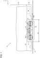
- Fig. 1 is a side view of an example of a bogie part of a railway vehicle without any movable cover device
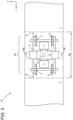
- Fig. 2 is a bottom view.
- the railway vehicle 51 has a body and bogies 52, and the body is, at both end parts thereof in the x direction, supported by the bogies 52 which move along a railway track 70.
- the body of the railway vehicle 51 includes a passenger room 53 located, in the z direction, above an underframe 55 making up a floor and an underfloor portion 54 located, in the z direction, below the underframe 55.
- the underfloor portion 54 includes underside closing plates 7 covering the underside facing the railway track 70 of the railway vehicle 51 and end-portion closing plates 6 approximately vertically rising continuously from the underside closing plates 7. Furthermore, in the underfloor portion 54, space portions (cavity portions) 58 where the bogies 52 are placed are provided. The space portions 58 are each formed in space partitioned by the underside of the underframe 55 located above the bogies 52 and the end-portion closing plates 6 provided on both sides in the x direction (front-rear direction) of each bogie 52. An electric device 56 is provided in a portion where an underside closing plate 7 is provided of the underfloor portion 54.
- Each bogie 52 is placed in a space portion 58 to be turnable within a horizontal plane with respect to the underframe 55 about a center pin 5 extending along the z direction.
- the bogie 52 includes a bogie frame 4, axles 3 held rotatably with respect to the bogie frame 4, wheels 2 fixed to both end parts in the y direction of each axle 3, and main motors 1 supported by the bogie frame 4.
- the two axles 3 are provided on both sides in the front-rear direction (in the x direction) of the bogie 52.
- the bogie 52 supports the underframe 55 via air springs 30 provided, to be around the center in the x direction, on both sides in the y direction.
- a windbreak plate 8 to suppress, during running, the wind hitting the main motors 1, etc. the bogie 52 is provided with is provided under a central part in the x direction of the bogie frame 4.
- an air flow 80a enters, as shown in Fig. 1 , the space portion 58 and hits the bogie 52.
- the air flow 80a having become turbulent by hitting the bogie 52 hits the end-portion closing plate 6 provided in a rear portion in the x direction of the bogie 52.
- an air flow (swirl) 80b along and around the y axis is generated in an upper portion in the z direction of the interior of the space portion 58.
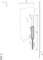
- Fig. 3 is a bottom view of a bogie part of a railway vehicle according to a first embodiment of the present invention.
- Fig. 4 is a sectional view taken along line A-A in Fig. 3 (the first embodiment).
- the railway car is additionally provided with configurations of movable cover devices 10A.
- the same parts as those shown in Figs. 1 and 2 are denoted by the same reference signs, and the description of such parts is omitted unless particularly required.
- the movable cover devices 10A each include a movable cover 11a to cover the underside of the space portion 58, an accommodation part 15a to accommodate the movable cover 11a, and drive devices 13 to drive the movable cover 11a.
- a pair of movable covers 11a are placed at the height of the underside closing plates 7, being as high as a lower part of the space portion 58. Also, the movable covers 11a move, in the x direction, in a manner of horizontally projecting from the end-portion closing plates 6 in the front-rear direction of the space portion 58 into the space portion 58. Also, in the y direction, the movable covers 11a cover the entire width of the space portion 58.
- Each accommodation part 15a is provided, to be approximately in parallel with the underframe 55 (see Fig. 1 ), in a portion on the side of an underside closing plate 7 of the underfloor portion 54.
- the accommodation part 15a is provided, near the joint between a lower end part of an end-portion closing plate 6 and an underside closing plate 7, at a height to be approximately as high as the underside closing plate 7.
- Each drive device 13 is provided in a portion on the side of an underside closing plate 7 of the underfloor portion 54 and makes up a cylinder system including a cylinder 13a and a rod 13b connected with the cylinder 13a.
- One end of the rod 13b is connected to a side part (a side part opposite to the bogie 52 side) of the movable cover 11a.
- movable cover 11a of the movable cover device 10A on the left side is shown in a state not covering the space portion 58 where the bogie 52 is provided (in a state with the space portion 58 open) .
- the movable cover 11a of the movable cover device 10A shown on the right side in Fig. 3 is in a state covering the space portion 58 where the bogie 52 is provided (in a state with the space portion 58 closed).
- This is an example representation for the sake of explanation, and the movable cover 11a on each side can be put in a covering state or in a not-covering state. Indications of "(OPEN)" and "(CLOSED)" in the subsequent drawings indicate the above-described states.
- the total dimension in the x direction of the pair of moving covers 11a is smaller than the dimension in the x direction of the space portion 58. Therefore, the movable covers 11a of the movable cover devices 10A cover the space portion 58 not entirely but partly (both end portions in the x direction). In a covering state, the movable covers 11a cover, as viewed from the bottom side, both end portions in the x direction of the bogie frame 4 and portions of the wheels 2. At this time, the movable covers 11a are in a state of covering to an extent not interfering with the wheels 2.
- each movable cover 11a is held at each end portion in the y direction by a guide rail 14a to be slidable in the x direction.
- the movable covers 11a are driven in the x direction by sliding the cylinders 13a of the drive devices 13.
- Each guide rail 14a is provided, as shown in Fig. 3 , to extend along the x direction at near an end portion in the y direction of the space portion 58 and is U-shaped, being open toward a central portion in the y direction.
- Each end portion in the y direction of each movable cover 11a is, as shown in Fig. 5 , held from above and below, each via a sliding part 16, by a guide rail 14a.
- the sliding parts 16 are for enabling smooth sliding by reducing friction between component members. Also, providing an inner step 11a1 in the rail-held portion on each side of each movable cover 11a makes alignment in the z direction possible between the bottom surfaces of the movable cover 11a and guide rail 14a.
- the guide rails 14a configured as described above can suppress, even when pressure fluctuations caused by the air flow 80a are applied to the movable covers 11a, vibrations in the z direction of the movable covers 11a and generation of noise attributable to vibrations. This makes it possible to extend the replacement cycle of the movable covers 11a and suppress noise generation caused by vibrations of the movable covers 11a.
- the railway vehicle 51 provided with the movable cover devices 10A configured as described above can reduce the open portion of each space portion 58 by partly closing the space portion 58, with the movable covers 11a, from both sides in the x direction of the space portion 58. Therefore, the air flow 80a flowing, when the railway vehicle 51 runs at high speed, below an underside closing plate 7 toward the space portion 58 advances along the surface of a movable cover 11a provided, on the upstream side, to be continuously from the underside closing plate 7.
- the air flow 80a then further advances, skipping a portion of the space portion 58, along the underside of the windbreak plate 8 the bogie 52 is provided with, then, again skipping a portion of the space portion 58, flows away toward the other movable cover 11a and the underside closing plate 7 on the downstream side.
- the movable cover 11a of each movable cover device 10A is made to partly close the space portion 58. This reduces the air resistance attributable to each space portion 58 where a bogie 52 of the railway vehicle 51 is accommodated.
- the movable cover 11a of each movable cover device 10A leaves the space portion 58 open. This allows easy maintenance and inspection of the bogie 52.
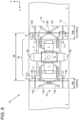
- Fig. 6 is a bottom view of a bogie part of a railway vehicle according to a second embodiment of the present invention
- Fig. 7 is a sectional view taken along line C-C in Fig. 6 (the second embodiment).
- the second embodiment will be described mainly about differences from the first embodiment, the same parts as those for the first embodiment will be denoted by the same reference signs, and the description of such parts will be omitted unless particularly required.
- Movable cover devices 10B each include a movable cover 11a' to cover the underside of a space portion 58, an accommodation part 15b to accommodate the movable cover 11a', and a drive device 13' to drive the movable cover 11a'.
- the drive device 13' is of a spider system and includes a pair of arms 13c and an arm drive device 13d. In the spider system, the two arms 13c are joined at around the arm centers and, by changing the angles of the two arms 13c, the relative positions (positions in the x direction) of parts connected to end parts of the arms 13c can be changed. The end parts of each of the pair of arms 13c are connected with a movable cover 11a' and an underside closing plate 7, respectively.
- the accommodation part 15b is provided, near the joint between a lower end part of an end-portion closing plate 6 and an underside closing plate 7, at a height to be approximately as high as the underside closing plate 7.
- the movable covers 11a' are provided to be slidable (openable/closable) in the x direction along guide rails 14b which are separated from each other in the y direction and extend along the x direction.
- the guide rails 14b are provided to project from the underside closing plates 7 into the space portion 58.
- each guide rail 14b has an upper part fixed to an underside closing plate 7 and a lower part forming guide parts 14b1 which protrude to both sides in the y direction and extend along the x direction.
- the guide parts 14b1 of each guide rail 14b are placed in a space portion 11a2 formed to extend along the x direction in the movable cover 11a'.
- the guide parts 14b1 mutually oppositely protruding to both sides are held from above and below by sliding parts 16 in the space portion 11a2.
- each movable cover device 10B provided with a drive device 13' employing a spider system can be made smaller than the dimension in the x direction of a movable cover device 10A of the first embodiment provided with drive devices 13 each employing a cylinder system. Therefore, a larger space portion for installing the electric device 56, etc. can be secured in the underfloor portion 54 of the railway vehicle 51.
- Fig. 8 is a side view of a bogie part of a railway vehicle according to a third embodiment of the present invention
- Fig. 9 is a sectional view taken along line D-D in Fig. 8 (the third embodiment).
- the third embodiment will be described mainly about differences from the first and second embodiments, the same parts as those for the first and second embodiments will be denoted by the same reference signs, and the description of such parts will be omitted unless particularly required.
- the movable cover devices 10C each include a movable cover 12 to cover the underside and a side part of a space portion 58, an accommodation part 15c to accommodate the movable cover 12, and drive devices 13 to drive the movable cover 12.
- the drive devices 13 each have a cylinder system configuration as in the first embodiment.
- the movable cover 12 integrally includes a bottom cover 12a covering a bottom portion and side covers 12b rising in the z direction continuously from both end parts in the y direction of the bottom cover 12a and covering both end parts in the y direction of the bogie 52.
- the configuration and covering range of the bottom cover 12a are the same as those of the movable covers 11a of the first embodiment.
- the side covers 12b cover, fully in the height direction (the z direction), the sides of the space portion 58.
- the accommodation part 15c is provided in a portion on the side where an underside closing plate 7 is provided of the underfloor portion 54 so that, when opening the space portion 58, the bottom cover 12a and side covers 12b can be accommodated therein.
- the portion to accommodate the bottom cover 12a of the accommodation part 15c is provided to be approximately as high as around where an end-portion closing plate 6 and an underside closing plate 7 are joined (that is, approximately as high as the underside closing plates 7).
- the portions to accommodate the side covers 12b are provided along the sides of the underfloor portion 54.
- the bottom of the bottom cover 12a is guided in the x direction using the configuration of the guide rails 14B shown in Fig. 7 described in connection with the second embodiment.
- the end parts in the z direction of the side covers 12b are guided by guide rails 14a' provided on both sides (surface parts on both sides) in the y direction of the underframe 55 of the railway vehicle 51.
- the guide rails 14a' are provided at both end parts in the y-direction as shown in Fig. 9 , and are U-shaped with the lower side open.
- the upper end part of each side cover 12b is held by a guide rail 14a' by being held from left and right each via a sliding part 16.
- the movable cover 12 is moved in the x direction by the drive devices 13. This causes the space portion 58 to be partly closed by the bottom cover 12a and the side covers 12b, so that the open portion of the space portion 58 is reduced. When opening the space portion 58, the movable cover 12 is accommodated in the accommodation part 15c.
- the railway vehicle 51 provided with the movable covers 12 can suppress, by means of the side covers 12b, hitting of wind flows against the sides (both end parts in the y direction) of each bogie 52. This reduces the running resistance of the railway vehicle 51 to realize energy saving. Furthermore, the side covers 12 suppress the propagation of noise generated in the space portion 58 to outside, so that the extra-vehicle noise generated when the railway vehicle 51 runs can be reduced.
- Fig. 10 is a bottom view of a bogie part of a railway vehicle according to a fourth embodiment of the present invention.
- Fig. 11 is a plan view of a bottom cover according to the fourth embodiment of the present invention, and
- Fig. 12 is a sectional view taken along line F-F in Fig. 11 (the fourth embodiment).
- Fig. 13 is a sectional view taken along line E-E in Fig. 10 (the fourth embodiment).
- the fourth embodiment will be described mainly about differences from the first to third embodiments, the same parts as those for the first to third embodiments will be denoted by the same reference signs, and the description of such parts will be omitted unless particularly required.
- Movable cover devices 10D of the fourth embodiment each include a movable cover 11b to cover a space portion 58, an accommodation part 15d to accommodate the movable cover 11b, and a drive device 13' to drive the movable cover 11b. Also, according to the fourth embodiment, no windbreak plate 8 is provided.
- the movable cover 11b is provided in a railway vehicle 51 in a manner of being divided into two, a first bottom cover 11b1 and a second bottom cover 11b2, in the x direction.
- the first bottom cover 11b1 moves in a manner of horizontally protruding from a portion on the side of an underside closing plate 7 of the underfloor portion 54, and the second bottom cover 11b2 in a manner of horizontally protruding from a portion on the side of the other underside closing plate 7 of the underfloor portion 54.
- the movable cover 11b can close the space portion 58 by bringing the leading end parts of the first bottom cover 11b1 and second bottom cover 11b2 into abutting contact.
- the first bottom cover 11b1 and the second bottom cover 11b2 each have two slit portions 11s formed in two rows along the x direction so as to avoid interference between the bottom covers and wheels 2 of the bogie 52.
- the slit portions 11s are open each at one end on the side of the leading end part in the x direction of the first bottom cover 11b1 or second bottom cover 11b2.
- Each accommodation part 15d is provided in a portion on the side of an underside closing plate 7 of the underfloor portion 54 to be approximately in parallel with the underframe 55 in a height position (in the z direction) the same as the accommodation parts 15a of the first embodiment.
- the space portion 58 is not closed (left open)
- the first bottom cover 11b1 is accommodated in the accommodation part 15d on the side of an underside closing plate 7 in the x direction
- the second bottom cover 11b2 is accommodated in the accommodation part 15d on the side of the other underside closing plate 7 in the x direction. This keeps the space portion 58 open.
- the drive device 13' employs a spider system the same as in the second embodiment.
- the drive device 13' includes a pair of arms 13c intersecting in an x-y plane, and an arm drive device 13d to drive the arms 13c.
- a drive device 13' is included in each of the first bottom cover 11b1 and the second bottom cover 11b2, and, each pair of arms 13c is connected, at end parts thereof, with the movable cover 11b (the first bottom cover 11b1 or the second bottom cover 11b2) and an underside closing plate 7, respectively.
- the end faces of the first bottom cover 11b1 and the second bottom cover 11b2 which mutually oppose when the bottom covers are closed are provided with concaves and convexes which engage when both covers 11b1 and 11b2 are closed.
- the opposing end faces of the two bottom covers 11b1 and 11b2 are provided with plural mutually engaging concaves 11q and convexes 11p (alternatingly four each) .
- mutually engaging concave 11w and convex 11v are provided.
- Each concave 11q has a pair of inclined parts on both sides in the y direction, the distance between which spreading in the y direction toward the open side.
- Each convex 11p has a pair of inclined parts on both sides in the y direction, the distance between which narrowing in the y direction toward the protruding side.
- the concave 11w has a pair of inclined parts on both sides in the z direction, the distance between which spreading in the z direction toward the open side.
- the convex 11v has a pair of inclined parts on both sides in the z direction, the distance between which narrowing in the z direction toward the protruding side.
- the air flow 80a under an underside closing plate 7 as shown in Fig. 1 does not flow into the space portion 58 accommodating the bogie 52. Therefore, the generation of an air flow 80b in a space portion above the bogie 52 can be prevented. Furthermore, hitting of the air flow 80a against the end-portion closing plate 6 on the downstream side of the bogie 52 can be suppressed. These make it possible to reduce the running energy of the railway vehicle 51 so as to promote energy saving. Furthermore, the propagation to the surrounding area of noise generated by joints, etc. bridged between the main motors 1 and axles 3 is blocked and suppressed by the movable cover 11b, so that vehicle exterior noise is reduced.
- Fig. 14 is a bottom view of a bogie part of a railway vehicle according to a fifth embodiment of the present invention
- Fig. 15 is a sectional view taken along line G-G in Fig. 14 (the fifth embodiment).
- the fifth embodiment will be described mainly about differences from the first to fourth embodiments, the same parts as those for the first to fourth embodiments will be denoted by the same reference signs, and the description of such parts will be omitted unless particularly required.
- Movable cover devices 10E include movable covers 11c1 and 11c2 to cover the underside of a space portion 58, accommodation parts 15e to accommodate the movable covers 11c1 and 11c2, and drive devices 13 to drive the movable covers 11c1 and 11c2. Furthermore, the space portion 58 where a bogie 52 of a railway vehicle 51 is positioned is provided, in a central portion in the x direction, with a bogie bottom cover 20 which is a fixed cover.
- the drive devices 13 each have a cylinder system configuration as in the first embodiment.
- the bogie bottom cover 20 extends, in the y direction, from end to end of the space portion 58, reaching from one side of the bogie 52 to the other side via the bottom part of the bogie 52.
- the upper end parts of side plates erected at both ends in the y direction of the bogie cover 20 are connected to both end parts in the y direction of the underframe (floor) 55 (see Fig. 1 ).
- the bogie bottom cover 20 has the same effects as a windbreak plate 8 (see Fig. 2 ) provided, under a center portion, both in the x direction and in the y direction, of a bogie 52. In the fourth embodiment, therefore, no windbreak plate 8 is provided.
- the movable cover 11c1 covers the bottom of a portion of the space portion 58, the portion ranging in the x direction from the lower end part of an end-portion closing plate 6 to the opposing end part of the bogie bottom cover 20.
- the movable cover 11c2 covers the bottom of another portion of the space portion 58, the another portion ranging in the x direction from the lower end part of the other end-portion closing plate 6 to the opposing end part of the bogie bottom cover 20. Therefore, the dimension in the x direction of the movable covers 11c1 and 11c2 is smaller by the length in the x direction of the bogie bottom cover 20 compared with the bottom covers 11b1 and 11b2 of the fourth embodiment.
- the movable covers 11c1 and 11c2 In the y direction, the movable covers 11c1 and 11c2 fully cover the space portion 58. Also, not to interfere with the wheels 2, the movable covers 11c1 and 11c2 each have two slit portions 11s which are positioned correspondingly to the wheels 2 and are open toward the wheels 2.
- Each accommodation part 15e is provided in a portion on the side of an underside closing plate 7 of the underfloor portion 54 to be approximately in parallel with the underframe 55 in a height position (in the z direction) the same as the accommodation parts 15a of the first embodiment.
- the movable cover 11c1 is accommodated in the accommodation part 15e on the side of an underside closing plate 7 in the x direction.
- the movable cover 11c2 is accommodated in the accommodation part 15e on the side of the other underside closing plate 7 in the x direction. This keeps the space portion 58 open.
- the bottom of the bogie 52 configures a continuous surface ranging from an underside closing plate 7 of the railway vehicle 51 to the other underside closing plate 7 of the railway vehicle 51 via the movable cover 11c1, the bogie bottom cover 20 and the movable cover 11c2.
- the air flow 80a under an underside closing plate 7 does not flow into the space portion 58 accommodating the bogie 52. Therefore, the generation of an air flow 80b in a space portion above the bogie 52 can be prevented. Furthermore, hitting of the air flow 80a against the end-portion closing plate 6 on the downstream side of the bogie 52 can be suppressed. These make it possible to reduce the running energy of the railway vehicle 51 so as to promote energy saving. Furthermore, the propagation to the surrounding area of noise generated by joints, etc. bridged between the main motors 1 and axles 3 is blocked and suppressed by the movable covers 11c1 and 11c2, so that vehicle exterior noise is reduced. Also, since the movable covers 11c1 and 11c2 can also keep the space portion 58 open, the bogie 52 can be maintained and inspected easily.
- Fig. 16 is a bottom view of a bogie part of a railway vehicle according to a sixth embodiment of the present invention.
- the sixth embodiment will be described mainly about differences from the first to fifth embodiments, the same parts as those for the first to fifth embodiments will be denoted by the same reference signs, and the description of such parts will be omitted unless particularly required.
- Movable cover devices 10F include movable covers 11d1 and 11d2 to cover a space portion 58, accommodation parts 15e to accommodate the movable covers 11d1 and 11d2, and drive devices 13 to drive the movable covers 11d1 and 11d2. Furthermore, the space portion 58 where a bogie 52 of a railway vehicle 51 is accommodated is provided, in a central portion in the x direction, with a bogie bottom cover 20 which is a fixed cover similar to that of the fifth embodiment.
- the drive devices 13 each have a cylinder system configuration as in the first embodiment.
- the movable covers 11d1 and 11d2 are, as a whole, configured similarly to the movable covers 11c1 and 11c2 of the fifth embodiment. Similarly to the fifth embodiment, not to interfere with the wheels 2, the movable covers 11d1 and 11d2 each have two slit portions 11s which are positioned correspondingly to the wheels 2 and are open toward the wheels 2.
- the accommodation parts 15e are the same as in the fifth embodiment.
- the movable covers 11d1 and 11d2 each have a portion on the side of one end in the y direction, being outward of the slit portion 11s on the same side, with a dimension L2 in the x direction of the portion (the dimension from the end-portion closing plate 6 on the corresponding side to the opposing end of the movable cover in a state of closing the space portion 58) being smaller than a dimension L1 in the x direction at the center in the y direction of the movable cover.
- a dimension L2 in the x direction of the portion the dimension from the end-portion closing plate 6 on the corresponding side to the opposing end of the movable cover in a state of closing the space portion 58
- an opening 60 is formed between the end part of each of the portions with a dimension L2 in the x direction and the bogie bottom cover 20.
- an opening 60 is formed at an end part on one side in the y direction of the movable cover 11d1 and also at an end part on the other side in the y direction of the movable cover 11d2.
- the openings 60 which are spaced apart in the x direction of the railway vehicle 51, are formed one to be at one end in the y direction and the other to be at the other end in the y direction of the railway vehicle 51.
- a part of an air flow 80c flowing under an underside closing plate 7 of the railway vehicle 51 enters the space portion 58 through an opening 60 formed by a movable cover 11d1.
- the part of the air flow 80c cools the main motors 1 that the bogie 52 is provided with, then flows out through the other opening 60 formed by the movable cover 11d2 and flows away toward under the underside closing plate 7 on the other side.
- the propagation to the surrounding area of noise generated by joints, etc. bridged between the main motors 1 and axles 3 is blocked and suppressed by the movable covers 11d1 and 11d2, so that vehicle exterior noise is reduced. Also, since the movable covers 11d1 and 11d2 can also keep the space portion 58 open, the bogie 52 can be maintained and inspected easily.
- Fig. 17 is an example of a flowchart showing a method of controlling cover drive devices applied to a railway vehicle according to the present invention.
- the flowchart shown in Fig. 17 is for when opening/closing the movable covers (11a, 11a', 11b, 11c1, 11c2, 11d1, 11d2, and 12) described above in connection with the first to sixth embodiments.
- the control processing can be performed, for example, at a control section provided in the railway vehicle 51.
- step S10 processing is started.
- step S20 whether or not the railway vehicle 51 is being operated at a predetermined speed or higher is determined.
- processing returns to a processing level above step S20, and a state with the movable covers not closed (a state with the space portion 58 open) is maintained.
- processing advances to the next step S30.
- step S30 by driving the drive devices 13 or 13', the movable covers are deployed, and the space portion 58 is partly or fully closed.
- step S20 vehicle is operated at a predetermined speed or higher
- step S30 movable covers are deployed (space portion 58 is closed)
- cases in which the movable covers are deployed are limited to when the turning in a horizontal plane of the bogie 52 is of a small degree.
- step S40 whether or not the railway vehicle is being operated at a predetermined speed or higher is determined.
- processing returns to a processing level above step S40, and a state with the movable covers closed (deployed) (a state with the space portion 58 partly or fully closed) is maintained.
- processing advances to the next step S50.
- step S50 by driving the drive devices 13 or 13', the movable covers are moved back (retreated), and the space portion 58 is set open.
- step S60 whether or not the operation of the railway vehicle 51 is to be ended is determined.
- processing returns to step S20.
- step S60 it is determined that the operation is to be ended
- step S70 maintaining a state with the movable covers not closed (a state with the space portion 58 open).
- the space portion 58 is not covered with the movable covers, so that the bogie 52 and surrounding parts can be easily inspected.
- the present invention is not limited to the above embodiments and includes various modifications.
- the above embodiments have been described in detail to make the invention easily understandable and are not necessarily limited to those with all the described configurations. It is also possible to replace a part of a configuration of an embodiment with a configuration of another embodiment or to add a configuration of an embodiment to a configuration of another embodiment. Also, an embodiment may be partly added to by another configuration or may be partly deleted or replaced by another configuration.
- a movable cover 12 has been described as integrally including a bottom cover 12a and side covers 12b, but it may be configured with separable parts. Also, the movable cover 12 may be attached with a sound absorbing material which absorbs noise.
Landscapes
- Engineering & Computer Science (AREA)
- Mechanical Engineering (AREA)
- Electric Propulsion And Braking For Vehicles (AREA)
- Current-Collector Devices For Electrically Propelled Vehicles (AREA)
Abstract
Description
- The present invention relates to a railway vehicle and a method of controlling movable covers for a railway vehicle, and more particularly, to a railway vehicle configured including covers to cover around bogies supporting the body of the railway vehicle and a method of controlling the covers.
- Reducing energy consumption during railway vehicle operation has been becoming increasingly important for environmental and cost-reduction reasons. The amount of energy consumed in railway systems is known to be relatively small compared with the amounts consumed in road vehicle and aviation systems, but further energy saving is desired.
- When a railroad vehicle is running, a considerable amount of energy is consumed to counter the running resistance. In the case of a high-speed train, in particular, air resistance accounts for a most part of the running resistance. To reduce aerodynamic drag, measures such as extending head shapes, adopting side skirts and reducing steps have been taken.
- However, since trains are generally required to be capable of running on curved tracks, the bogies of trains require space in which the bogies can turn along curved tracks. The cavities (hollow portions) that provide such space increase aerodynamic drag.
- In
patent literature 1, a technology in which opening of a cavity accommodating a bogie of a railway vehicle is covered with a mesh cover is described. - In
patent literature 2, a technology in which a bogie is provided with covers covering sides and a bottom of a cavity portion is described. -
- Patent literature 1: Publication of
Japanese Patent No. 4331025 - Patent literature 2: Publication of
Japanese Patent No. 6193303 - To suppress air flowing into a cavity around a bogie, it is effective, as described in
patent literature 1, to cover open portions of the cavity as much as possible and reduce air-flow speed via meshes. However, when a railway vehicle runs, the bogies of the railway vehicle turn following the rails, so that the covers are required to respond to the movement. - For this, there is a method in which, as described in
patent literature 2, covers are fixed to bogies. Then, the covers move together with the bogies, so that flowing of air into cavities around the bogies can be suppressed. On the other hand, it becomes necessary to remove the covers when bogie maintenance is performed. - In view of the above problems, an object of the present invention is to provide a railway vehicle and a method of controlling movable covers for a railway vehicle which make it possible to save energy by suppressing air flows into space portions around bogies of a running railway vehicle and make bogie maintenance easy.
- To solve the above problems, a typical railway vehicle according to the present invention includes a body, a bogie to support the body, and a movable cover device. The body includes a passenger room provided above an underframe, the underframe making up a floor, and an underfloor portion provided below the underframe. The underfloor portion is provided with a space portion to accommodate the bogie. The space portion is formed in space partitioned by an end-portion closing plate rising in the height direction from an end part on the bogie side of each underside closing plate which is provided downward of the underframe to be approximately in parallel with the underframe and the underside of the underframe. The movable cover device includes a movable cover which covers the underside of the space portion at least partly from a lower end part of an end-portion closing plate, an accommodation part to accommodate the movable cover, and a drive device to drive the movable cover.
- The railway vehicle and the method of controlling movable covers for a railway vehicle according to the present invention make it possible to save energy by suppressing air flows into space portions around bogies of a running railway vehicle and make bogie maintenance easy.
-
-
Fig. 1 is a side view of an example of a bogie part of a railway vehicle without any movable cover device. -
Fig. 2 is a bottom view of an example of a bogie part of a railway vehicle without any movable cover device. -
Fig. 3 is a bottom view of a bogie part of a railway vehicle according to a first embodiment of the present invention. -
Fig. 4 is a sectional view taken along line A-A inFig. 3 (the first embodiment). -
Fig. 5 is a sectional view taken along line B-B inFig. 3 (the first embodiment). -
Fig. 6 is a bottom view of a bogie part of a railway vehicle according to a second embodiment of the present invention. -
Fig. 7 is a sectional view taken along line C-C inFig. 6 (the second embodiment). -
Fig. 8 is a side view of a bogie part of a railway vehicle according to a third embodiment of the present invention. -
Fig. 9 is a sectional view taken along line D-D inFig. 8 (the third embodiment). -
Fig. 10 is a bottom view of a bogie part of a railway vehicle according to a fourth embodiment of the present invention. -
Fig. 11 is a plan view of a bottom cover according to the fourth embodiment of the present invention. -
Fig. 12 is a sectional view taken along line F-F inFig. 11 (the fourth embodiment). -
Fig. 13 is a sectional view taken along line E-E inFig. 10 (the fourth embodiment). -
Fig. 14 is a bottom view of a bogie part of a railway vehicle according to a fifth embodiment of the present invention. -
Fig. 15 is a sectional view taken along line G-G inFig. 14 (the fifth embodiment). -
Fig. 16 is a bottom view of a bogie part of a railway vehicle according to a sixth embodiment of the present invention. -
Fig. 17 is an example of a flowchart showing a method of controlling cover drive devices applied to a railway vehicle according to the present invention. - Forms of implementation of the present invention will be described with reference to
Figs. 1 to 17 . First, directions in each drawing will be defined. The direction of running or the longitudinal direction (front-rear direction) of arailway vehicle 51 is defined as x direction, the width direction (left-right direction) of therailway vehicle 51 is defined as y direction, and the height direction (upper-lower direction) of therailway vehicle 51 is defined as z direction. The directions may hereinafter be referred to simply as the x direction, the y direction and the z direction. -
Fig. 1 is a side view of an example of a bogie part of a railway vehicle without any movable cover device, andFig. 2 is a bottom view. - The
railway vehicle 51 has a body andbogies 52, and the body is, at both end parts thereof in the x direction, supported by thebogies 52 which move along arailway track 70. The body of therailway vehicle 51 includes apassenger room 53 located, in the z direction, above anunderframe 55 making up a floor and anunderfloor portion 54 located, in the z direction, below theunderframe 55. - The
underfloor portion 54 includesunderside closing plates 7 covering the underside facing therailway track 70 of therailway vehicle 51 and end-portion closing plates 6 approximately vertically rising continuously from theunderside closing plates 7. Furthermore, in theunderfloor portion 54, space portions (cavity portions) 58 where thebogies 52 are placed are provided. Thespace portions 58 are each formed in space partitioned by the underside of theunderframe 55 located above thebogies 52 and the end-portion closing plates 6 provided on both sides in the x direction (front-rear direction) of eachbogie 52. Anelectric device 56 is provided in a portion where anunderside closing plate 7 is provided of theunderfloor portion 54. - Each
bogie 52 is placed in aspace portion 58 to be turnable within a horizontal plane with respect to theunderframe 55 about acenter pin 5 extending along the z direction. Thebogie 52 includes abogie frame 4,axles 3 held rotatably with respect to thebogie frame 4,wheels 2 fixed to both end parts in the y direction of eachaxle 3, andmain motors 1 supported by thebogie frame 4. The twoaxles 3 are provided on both sides in the front-rear direction (in the x direction) of thebogie 52. Thebogie 52 supports theunderframe 55 viaair springs 30 provided, to be around the center in the x direction, on both sides in the y direction. Awindbreak plate 8 to suppress, during running, the wind hitting themain motors 1, etc. thebogie 52 is provided with is provided under a central part in the x direction of thebogie frame 4. - In cases where no movable cover device is provided, when the
railway vehicle 51 runs at high speed, anair flow 80a enters, as shown inFig. 1 , thespace portion 58 and hits thebogie 52. Theair flow 80a having become turbulent by hitting thebogie 52 hits the end-portion closing plate 6 provided in a rear portion in the x direction of thebogie 52. Furthermore, an air flow (swirl) 80b along and around the y axis is generated in an upper portion in the z direction of the interior of thespace portion 58. Theseair flow 80a flowing into thespace portion 58 andair flow 80b generated inside thespace portion 58 make up air resistance against the running direction of therailway vehicle 51, and therailway vehicle 51 running at high speed is caused to consume a large running energy. -
Fig. 3 is a bottom view of a bogie part of a railway vehicle according to a first embodiment of the present invention.Fig. 4 is a sectional view taken along line A-A inFig. 3 (the first embodiment). According to the first embodiment, compared with the railway vehicle, shown inFigs. 1 and2 , not provided with any movable cover device, the railway car is additionally provided with configurations ofmovable cover devices 10A. InFig. 3 , the same parts as those shown inFigs. 1 and2 are denoted by the same reference signs, and the description of such parts is omitted unless particularly required. - As shown in
Figs. 3 and4 , themovable cover devices 10A each include amovable cover 11a to cover the underside of thespace portion 58, anaccommodation part 15a to accommodate themovable cover 11a, and drivedevices 13 to drive themovable cover 11a. - A pair of
movable covers 11a are placed at the height of theunderside closing plates 7, being as high as a lower part of thespace portion 58. Also, themovable covers 11a move, in the x direction, in a manner of horizontally projecting from the end-portion closing plates 6 in the front-rear direction of thespace portion 58 into thespace portion 58. Also, in the y direction, themovable covers 11a cover the entire width of thespace portion 58. - Each
accommodation part 15a is provided, to be approximately in parallel with the underframe 55 (seeFig. 1 ), in a portion on the side of anunderside closing plate 7 of theunderfloor portion 54. Theaccommodation part 15a is provided, near the joint between a lower end part of an end-portion closing plate 6 and anunderside closing plate 7, at a height to be approximately as high as theunderside closing plate 7. When opening thespace portion 58, themovable covers 11a are accommodated into theaccommodation parts 15a. - Each
drive device 13 is provided in a portion on the side of anunderside closing plate 7 of theunderfloor portion 54 and makes up a cylinder system including acylinder 13a and arod 13b connected with thecylinder 13a. One end of therod 13b is connected to a side part (a side part opposite to thebogie 52 side) of themovable cover 11a. - In
Fig. 3 , themovable cover 11a of themovable cover device 10A on the left side is shown in a state not covering thespace portion 58 where thebogie 52 is provided (in a state with thespace portion 58 open) . Themovable cover 11a of themovable cover device 10A shown on the right side inFig. 3 is in a state covering thespace portion 58 where thebogie 52 is provided (in a state with thespace portion 58 closed). This is an example representation for the sake of explanation, and themovable cover 11a on each side can be put in a covering state or in a not-covering state. Indications of "(OPEN)" and "(CLOSED)" in the subsequent drawings indicate the above-described states. - As shown in
Fig. 3 , the total dimension in the x direction of the pair of movingcovers 11a is smaller than the dimension in the x direction of thespace portion 58. Therefore, themovable covers 11a of themovable cover devices 10A cover thespace portion 58 not entirely but partly (both end portions in the x direction). In a covering state, themovable covers 11a cover, as viewed from the bottom side, both end portions in the x direction of thebogie frame 4 and portions of thewheels 2. At this time, themovable covers 11a are in a state of covering to an extent not interfering with thewheels 2. - As shown in
Fig. 5 , eachmovable cover 11a is held at each end portion in the y direction by aguide rail 14a to be slidable in the x direction. Themovable covers 11a are driven in the x direction by sliding thecylinders 13a of thedrive devices 13. Eachguide rail 14a is provided, as shown inFig. 3 , to extend along the x direction at near an end portion in the y direction of thespace portion 58 and is U-shaped, being open toward a central portion in the y direction. Each end portion in the y direction of eachmovable cover 11a is, as shown inFig. 5 , held from above and below, each via a slidingpart 16, by aguide rail 14a. The slidingparts 16 are for enabling smooth sliding by reducing friction between component members. Also, providing an inner step 11a1 in the rail-held portion on each side of eachmovable cover 11a makes alignment in the z direction possible between the bottom surfaces of themovable cover 11a andguide rail 14a. - The
guide rails 14a configured as described above can suppress, even when pressure fluctuations caused by theair flow 80a are applied to themovable covers 11a, vibrations in the z direction of themovable covers 11a and generation of noise attributable to vibrations. This makes it possible to extend the replacement cycle of themovable covers 11a and suppress noise generation caused by vibrations of themovable covers 11a. - The
railway vehicle 51 provided with themovable cover devices 10A configured as described above can reduce the open portion of eachspace portion 58 by partly closing thespace portion 58, with themovable covers 11a, from both sides in the x direction of thespace portion 58. Therefore, theair flow 80a flowing, when therailway vehicle 51 runs at high speed, below anunderside closing plate 7 toward thespace portion 58 advances along the surface of amovable cover 11a provided, on the upstream side, to be continuously from theunderside closing plate 7. Theair flow 80a then further advances, skipping a portion of thespace portion 58, along the underside of thewindbreak plate 8 thebogie 52 is provided with, then, again skipping a portion of thespace portion 58, flows away toward the othermovable cover 11a and theunderside closing plate 7 on the downstream side. - In this way, the amount of air flowing into the
space portion 58 is reduced, so that both theair flow 80a passing thebogie 52 and hitting the end-portion closing plate 6 on the downstream side and theair flow 80b swirling in an upper portion of thespace portion 58 can be reduced. This makes it possible to reduce the air resistance against and the running energy used by therailway vehicle 51 so as to promote energy saving. - Furthermore, when the railway vehicle runs at a speed higher than a predetermined speed, the
movable cover 11a of eachmovable cover device 10A is made to partly close thespace portion 58. This reduces the air resistance attributable to eachspace portion 58 where abogie 52 of therailway vehicle 51 is accommodated. On the other hand, when therailway vehicle 51 runs at a speed lower than a predetermined speed or is stopped, themovable cover 11a of eachmovable cover device 10A leaves thespace portion 58 open. This allows easy maintenance and inspection of thebogie 52. -
Fig. 6 is a bottom view of a bogie part of a railway vehicle according to a second embodiment of the present invention, andFig. 7 is a sectional view taken along line C-C inFig. 6 (the second embodiment). The second embodiment will be described mainly about differences from the first embodiment, the same parts as those for the first embodiment will be denoted by the same reference signs, and the description of such parts will be omitted unless particularly required. -
Movable cover devices 10B according to the second embodiment each include amovable cover 11a' to cover the underside of aspace portion 58, an accommodation part 15b to accommodate themovable cover 11a', and a drive device 13' to drive themovable cover 11a'. The drive device 13' is of a spider system and includes a pair ofarms 13c and anarm drive device 13d. In the spider system, the twoarms 13c are joined at around the arm centers and, by changing the angles of the twoarms 13c, the relative positions (positions in the x direction) of parts connected to end parts of thearms 13c can be changed. The end parts of each of the pair ofarms 13c are connected with amovable cover 11a' and anunderside closing plate 7, respectively. The accommodation part 15b is provided, near the joint between a lower end part of an end-portion closing plate 6 and anunderside closing plate 7, at a height to be approximately as high as theunderside closing plate 7. When opening thespace portion 58, themovable cover 11a' is accommodated into the accommodation part 15b. - The
movable covers 11a' are provided to be slidable (openable/closable) in the x direction alongguide rails 14b which are separated from each other in the y direction and extend along the x direction. The guide rails 14b are provided to project from theunderside closing plates 7 into thespace portion 58. As shown inFig. 7 , eachguide rail 14b has an upper part fixed to anunderside closing plate 7 and a lower part forming guide parts 14b1 which protrude to both sides in the y direction and extend along the x direction. The guide parts 14b1 of eachguide rail 14b are placed in a space portion 11a2 formed to extend along the x direction in themovable cover 11a'. The guide parts 14b1 mutually oppositely protruding to both sides are held from above and below by slidingparts 16 in the space portion 11a2. - In the configuration described above, when a drive device 13' is driven, a pair of
arms 13c spread or contract centering in the plane of anunderside closing plate 7. This makes it possible to drive amovable cover 11a' in the x direction relative to theunderside closing plate 7. At this time, the configuration of theguide rails 14b allows themovable cover 11a' to be slid smoothly. - The dimension in the x direction of each
movable cover device 10B provided with a drive device 13' employing a spider system can be made smaller than the dimension in the x direction of amovable cover device 10A of the first embodiment provided withdrive devices 13 each employing a cylinder system. Therefore, a larger space portion for installing theelectric device 56, etc. can be secured in theunderfloor portion 54 of therailway vehicle 51. - Other effects of the railway vehicle provided with the
movable cover devices 10B according to the second embodiment are the same as cited for the first embodiment. Namely, the air resistance against and the running energy used by therailway vehicle 51 when running at high speed can be reduced, and also maintenance and inspection of thebogies 52 can be made easily. -
Fig. 8 is a side view of a bogie part of a railway vehicle according to a third embodiment of the present invention, andFig. 9 is a sectional view taken along line D-D inFig. 8 (the third embodiment). The third embodiment will be described mainly about differences from the first and second embodiments, the same parts as those for the first and second embodiments will be denoted by the same reference signs, and the description of such parts will be omitted unless particularly required. - The
movable cover devices 10C according to the third embodiment each include amovable cover 12 to cover the underside and a side part of aspace portion 58, anaccommodation part 15c to accommodate themovable cover 12, and drivedevices 13 to drive themovable cover 12. Thedrive devices 13 each have a cylinder system configuration as in the first embodiment. - As shown in
Fig. 9 , themovable cover 12 integrally includes abottom cover 12a covering a bottom portion and side covers 12b rising in the z direction continuously from both end parts in the y direction of thebottom cover 12a and covering both end parts in the y direction of thebogie 52. The configuration and covering range of thebottom cover 12a are the same as those of themovable covers 11a of the first embodiment. Also, the side covers 12b cover, fully in the height direction (the z direction), the sides of thespace portion 58. - The
accommodation part 15c is provided in a portion on the side where anunderside closing plate 7 is provided of theunderfloor portion 54 so that, when opening thespace portion 58, thebottom cover 12a and side covers 12b can be accommodated therein. The portion to accommodate thebottom cover 12a of theaccommodation part 15c is provided to be approximately as high as around where an end-portion closing plate 6 and anunderside closing plate 7 are joined (that is, approximately as high as the underside closing plates 7). The portions to accommodate the side covers 12b are provided along the sides of theunderfloor portion 54. - Though not shown, the bottom of the
bottom cover 12a is guided in the x direction using the configuration of the guide rails 14B shown inFig. 7 described in connection with the second embodiment. Also, the end parts in the z direction of the side covers 12b are guided byguide rails 14a' provided on both sides (surface parts on both sides) in the y direction of theunderframe 55 of therailway vehicle 51. The guide rails 14a' are provided at both end parts in the y-direction as shown inFig. 9 , and are U-shaped with the lower side open. The upper end part of eachside cover 12b is held by aguide rail 14a' by being held from left and right each via a slidingpart 16. - The
movable cover 12 is moved in the x direction by thedrive devices 13. This causes thespace portion 58 to be partly closed by thebottom cover 12a and the side covers 12b, so that the open portion of thespace portion 58 is reduced. When opening thespace portion 58, themovable cover 12 is accommodated in theaccommodation part 15c. - Therefore, in addition to having the advantageous effects described in connection with the first and second embodiments, the
railway vehicle 51 provided with themovable covers 12 can suppress, by means of the side covers 12b, hitting of wind flows against the sides (both end parts in the y direction) of eachbogie 52. This reduces the running resistance of therailway vehicle 51 to realize energy saving. Furthermore, the side covers 12 suppress the propagation of noise generated in thespace portion 58 to outside, so that the extra-vehicle noise generated when therailway vehicle 51 runs can be reduced. -
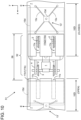
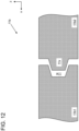
Fig. 10 is a bottom view of a bogie part of a railway vehicle according to a fourth embodiment of the present invention.Fig. 11 is a plan view of a bottom cover according to the fourth embodiment of the present invention, andFig. 12 is a sectional view taken along line F-F inFig. 11 (the fourth embodiment). -
Fig. 13 is a sectional view taken along line E-E inFig. 10 (the fourth embodiment). The fourth embodiment will be described mainly about differences from the first to third embodiments, the same parts as those for the first to third embodiments will be denoted by the same reference signs, and the description of such parts will be omitted unless particularly required. -
Movable cover devices 10D of the fourth embodiment each include amovable cover 11b to cover aspace portion 58, anaccommodation part 15d to accommodate themovable cover 11b, and a drive device 13' to drive themovable cover 11b. Also, according to the fourth embodiment, nowindbreak plate 8 is provided. - As shown in
Fig. 10 , themovable cover 11b is provided in arailway vehicle 51 in a manner of being divided into two, a first bottom cover 11b1 and a second bottom cover 11b2, in the x direction. The first bottom cover 11b1 moves in a manner of horizontally protruding from a portion on the side of anunderside closing plate 7 of theunderfloor portion 54, and the second bottom cover 11b2 in a manner of horizontally protruding from a portion on the side of the otherunderside closing plate 7 of theunderfloor portion 54. Themovable cover 11b can close thespace portion 58 by bringing the leading end parts of the first bottom cover 11b1 and second bottom cover 11b2 into abutting contact. When this occurs, the underside of thespace portion 58 is fully covered. For this, the first bottom cover 11b1 and the second bottom cover 11b2 each have two slitportions 11s formed in two rows along the x direction so as to avoid interference between the bottom covers andwheels 2 of thebogie 52. Theslit portions 11s are open each at one end on the side of the leading end part in the x direction of the first bottom cover 11b1 or second bottom cover 11b2. When thespace portion 58 is closed by themovable cover 11b,wheels 2 protrude downward through theslit portions 11s. - Each
accommodation part 15d is provided in a portion on the side of anunderside closing plate 7 of theunderfloor portion 54 to be approximately in parallel with theunderframe 55 in a height position (in the z direction) the same as theaccommodation parts 15a of the first embodiment. When thespace portion 58 is not closed (left open), the first bottom cover 11b1 is accommodated in theaccommodation part 15d on the side of anunderside closing plate 7 in the x direction and the second bottom cover 11b2 is accommodated in theaccommodation part 15d on the side of the otherunderside closing plate 7 in the x direction. This keeps thespace portion 58 open. - The drive device 13' employs a spider system the same as in the second embodiment. The drive device 13' includes a pair of
arms 13c intersecting in an x-y plane, and anarm drive device 13d to drive thearms 13c. A drive device 13' is included in each of the first bottom cover 11b1 and the second bottom cover 11b2, and, each pair ofarms 13c is connected, at end parts thereof, with themovable cover 11b (the first bottom cover 11b1 or the second bottom cover 11b2) and anunderside closing plate 7, respectively. - The end faces of the first bottom cover 11b1 and the second bottom cover 11b2 which mutually oppose when the bottom covers are closed are provided with concaves and convexes which engage when both covers 11b1 and 11b2 are closed. When viewed in an x-y plane (see
Fig. 11 ), the opposing end faces of the two bottom covers 11b1 and 11b2 are provided with plural mutually engagingconcaves 11q andconvexes 11p (alternatingly four each) . Also, when viewed in an x-z plane (seeFig. 12 ), mutually engaging concave 11w and convex 11v are provided. Each concave 11q has a pair of inclined parts on both sides in the y direction, the distance between which spreading in the y direction toward the open side. Each convex 11p has a pair of inclined parts on both sides in the y direction, the distance between which narrowing in the y direction toward the protruding side. The concave 11w has a pair of inclined parts on both sides in the z direction, the distance between which spreading in the z direction toward the open side. The convex 11v has a pair of inclined parts on both sides in the z direction, the distance between which narrowing in the z direction toward the protruding side. By approximately aligning the angles of their inclined parts, they can serve as guides for appropriate positioning. - When the two bottom covers 11b1 and 11b2 are closed, the engagement between
concaves 11q and convexes 11p suppresses misalignment by preventing shifting in the y direction. Also, the engagement between the concave 11w and the convex 11v suppresses misalignment by preventing shifting in the z direction. Since these allow themovable cover 11b to have a continuous surface, the generation of aerodynamic noise from where the two bottom covers 11b1 and 11b2 oppose each other can be suppressed. Furthermore, the increase of running resistance attributable to air turbulence generated where the two bottom covers 11b1 and 11b2 oppose each other can be suppressed. - In the above configuration, the
air flow 80a under anunderside closing plate 7 as shown inFig. 1 does not flow into thespace portion 58 accommodating thebogie 52. Therefore, the generation of anair flow 80b in a space portion above thebogie 52 can be prevented. Furthermore, hitting of theair flow 80a against the end-portion closing plate 6 on the downstream side of thebogie 52 can be suppressed. These make it possible to reduce the running energy of therailway vehicle 51 so as to promote energy saving. Furthermore, the propagation to the surrounding area of noise generated by joints, etc. bridged between themain motors 1 andaxles 3 is blocked and suppressed by themovable cover 11b, so that vehicle exterior noise is reduced. -
Fig. 14 is a bottom view of a bogie part of a railway vehicle according to a fifth embodiment of the present invention, andFig. 15 is a sectional view taken along line G-G inFig. 14 (the fifth embodiment). The fifth embodiment will be described mainly about differences from the first to fourth embodiments, the same parts as those for the first to fourth embodiments will be denoted by the same reference signs, and the description of such parts will be omitted unless particularly required. -
Movable cover devices 10E according to the fifth embodiment include movable covers 11c1 and 11c2 to cover the underside of aspace portion 58,accommodation parts 15e to accommodate the movable covers 11c1 and 11c2, and drivedevices 13 to drive the movable covers 11c1 and 11c2. Furthermore, thespace portion 58 where abogie 52 of arailway vehicle 51 is positioned is provided, in a central portion in the x direction, with abogie bottom cover 20 which is a fixed cover. Thedrive devices 13 each have a cylinder system configuration as in the first embodiment. - The
bogie bottom cover 20 extends, in the y direction, from end to end of thespace portion 58, reaching from one side of thebogie 52 to the other side via the bottom part of thebogie 52. The upper end parts of side plates erected at both ends in the y direction of thebogie cover 20 are connected to both end parts in the y direction of the underframe (floor) 55 (seeFig. 1 ). Thebogie bottom cover 20 has the same effects as a windbreak plate 8 (seeFig. 2 ) provided, under a center portion, both in the x direction and in the y direction, of abogie 52. In the fourth embodiment, therefore, nowindbreak plate 8 is provided. - The movable cover 11c1 covers the bottom of a portion of the
space portion 58, the portion ranging in the x direction from the lower end part of an end-portion closing plate 6 to the opposing end part of thebogie bottom cover 20. The movable cover 11c2 covers the bottom of another portion of thespace portion 58, the another portion ranging in the x direction from the lower end part of the other end-portion closing plate 6 to the opposing end part of thebogie bottom cover 20. Therefore, the dimension in the x direction of the movable covers 11c1 and 11c2 is smaller by the length in the x direction of thebogie bottom cover 20 compared with the bottom covers 11b1 and 11b2 of the fourth embodiment. In the y direction, the movable covers 11c1 and 11c2 fully cover thespace portion 58. Also, not to interfere with thewheels 2, the movable covers 11c1 and 11c2 each have two slitportions 11s which are positioned correspondingly to thewheels 2 and are open toward thewheels 2. - Each
accommodation part 15e is provided in a portion on the side of anunderside closing plate 7 of theunderfloor portion 54 to be approximately in parallel with theunderframe 55 in a height position (in the z direction) the same as theaccommodation parts 15a of the first embodiment. In a state where thespace portion 58 is not closed, the movable cover 11c1 is accommodated in theaccommodation part 15e on the side of anunderside closing plate 7 in the x direction. Also, the movable cover 11c2 is accommodated in theaccommodation part 15e on the side of the otherunderside closing plate 7 in the x direction. This keeps thespace portion 58 open. - When the
space portion 58 is closed by the movable covers 11c1 and 11c2, the bottom of thebogie 52 configures a continuous surface ranging from anunderside closing plate 7 of therailway vehicle 51 to the otherunderside closing plate 7 of therailway vehicle 51 via the movable cover 11c1, thebogie bottom cover 20 and the movable cover 11c2. - In the above configuration, the
air flow 80a under an underside closing plate 7 (seeFig. 1 ) does not flow into thespace portion 58 accommodating thebogie 52. Therefore, the generation of anair flow 80b in a space portion above thebogie 52 can be prevented. Furthermore, hitting of theair flow 80a against the end-portion closing plate 6 on the downstream side of thebogie 52 can be suppressed. These make it possible to reduce the running energy of therailway vehicle 51 so as to promote energy saving. Furthermore, the propagation to the surrounding area of noise generated by joints, etc. bridged between themain motors 1 andaxles 3 is blocked and suppressed by the movable covers 11c1 and 11c2, so that vehicle exterior noise is reduced. Also, since the movable covers 11c1 and 11c2 can also keep thespace portion 58 open, thebogie 52 can be maintained and inspected easily. -
Fig. 16 is a bottom view of a bogie part of a railway vehicle according to a sixth embodiment of the present invention. The sixth embodiment will be described mainly about differences from the first to fifth embodiments, the same parts as those for the first to fifth embodiments will be denoted by the same reference signs, and the description of such parts will be omitted unless particularly required. -
Movable cover devices 10F according to the sixth embodiment include movable covers 11d1 and 11d2 to cover aspace portion 58,accommodation parts 15e to accommodate the movable covers 11d1 and 11d2, and drivedevices 13 to drive the movable covers 11d1 and 11d2. Furthermore, thespace portion 58 where abogie 52 of arailway vehicle 51 is accommodated is provided, in a central portion in the x direction, with abogie bottom cover 20 which is a fixed cover similar to that of the fifth embodiment. Thedrive devices 13 each have a cylinder system configuration as in the first embodiment. - The movable covers 11d1 and 11d2 are, as a whole, configured similarly to the movable covers 11c1 and 11c2 of the fifth embodiment. Similarly to the fifth embodiment, not to interfere with the
wheels 2, the movable covers 11d1 and 11d2 each have two slitportions 11s which are positioned correspondingly to thewheels 2 and are open toward thewheels 2. Theaccommodation parts 15e are the same as in the fifth embodiment. - Also, the movable covers 11d1 and 11d2 each have a portion on the side of one end in the y direction, being outward of the
slit portion 11s on the same side, with a dimension L2 in the x direction of the portion (the dimension from the end-portion closing plate 6 on the corresponding side to the opposing end of the movable cover in a state of closing the space portion 58) being smaller than a dimension L1 in the x direction at the center in the y direction of the movable cover. In this configuration, when the movable covers 11d1 and 11d2 are slid out and thespace portion 58 is closed, anopening 60 is formed between the end part of each of the portions with a dimension L2 in the x direction and thebogie bottom cover 20. Namely, anopening 60 is formed at an end part on one side in the y direction of the movable cover 11d1 and also at an end part on the other side in the y direction of the movable cover 11d2. Thus, theopenings 60, which are spaced apart in the x direction of therailway vehicle 51, are formed one to be at one end in the y direction and the other to be at the other end in the y direction of therailway vehicle 51. - With the pair of
openings 60 formed as described above, a part of anair flow 80c flowing under anunderside closing plate 7 of therailway vehicle 51 enters thespace portion 58 through anopening 60 formed by a movable cover 11d1. After entering thespace portion 58, the part of theair flow 80c cools themain motors 1 that thebogie 52 is provided with, then flows out through theother opening 60 formed by the movable cover 11d2 and flows away toward under theunderside closing plate 7 on the other side. - In the above configuration, a part of the
air flow 80c flowing under anunderside closing plate 7 enters thespace portion 58 accommodating thebogie 52 and can effectively cool themain motors 1. Furthermore, most of theair flow 80c does not enter thespace portion 58. Therefore, the generation of anair flow 80b above thebogie 52 and anair flow 80a hitting the end-portion closing plate 6 on the downstream side as shown inFig. 1 can be suppressed. This makes it possible to reduce the running energy of therailway vehicle 51 and promote energy saving. - Furthermore, the propagation to the surrounding area of noise generated by joints, etc. bridged between the
main motors 1 andaxles 3 is blocked and suppressed by the movable covers 11d1 and 11d2, so that vehicle exterior noise is reduced. Also, since the movable covers 11d1 and 11d2 can also keep thespace portion 58 open, thebogie 52 can be maintained and inspected easily. -
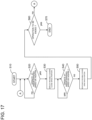
Fig. 17 is an example of a flowchart showing a method of controlling cover drive devices applied to a railway vehicle according to the present invention. The flowchart shown inFig. 17 is for when opening/closing the movable covers (11a, 11a', 11b, 11c1, 11c2, 11d1, 11d2, and 12) described above in connection with the first to sixth embodiments. The control processing can be performed, for example, at a control section provided in therailway vehicle 51. - In step S10, processing is started.
- Next, in step S20, whether or not the
railway vehicle 51 is being operated at a predetermined speed or higher is determined. When it is determined in step S20 that the vehicle is not being operated at a predetermined speed or higher, processing returns to a processing level above step S20, and a state with the movable covers not closed (a state with thespace portion 58 open) is maintained. When it is determined in step S20 that the vehicle is being operated at a predetermined speed or higher, processing advances to the next step S30. - In step S30, by driving the
drive devices 13 or 13', the movable covers are deployed, and thespace portion 58 is partly or fully closed. - When running at a predetermined speed or higher, the
railway vehicle 51 runs on a main line where the radius of curvature is set to be equal to or larger than a predetermined value and does not run on a track with a small radius of curvature. Therefore, when the railway vehicle runs meeting the condition, turning of thebogie 52 in a horizontal plane remains in a narrow range. With the processing configured including step S20 (vehicle is operated at a predetermined speed or higher) and step S30 (movable covers are deployed (space portion 58 is closed)), cases in which the movable covers are deployed are limited to when the turning in a horizontal plane of thebogie 52 is of a small degree. This makes it possible, for example, to make the dimension in the y direction of each slitportion 11s formed in the movable covers smaller to reduce the running resistance and to, thereby, more effectively suppress the increase of noise. If fixed covers are used (instead of the movable covers), it is necessary to make the dimension in the y direction of each slitportion 11s larger so as to allow, during low-speed running, large turning of thebogie 52. In such cases, it is difficult to effectively suppress the increase of running resistance and the generation of noise. - Next, in step S40, whether or not the railway vehicle is being operated at a predetermined speed or higher is determined. When, in step S40, it is determined that the railway vehicle is being operated at a predetermined speed or higher, processing returns to a processing level above step S40, and a state with the movable covers closed (deployed) (a state with the
space portion 58 partly or fully closed) is maintained. When it is determined in step S40 that the vehicle is not being operated at a predetermined speed or higher, processing advances to the next step S50. - In step S50, by driving the
drive devices 13 or 13', the movable covers are moved back (retreated), and thespace portion 58 is set open. - In step S60, whether or not the operation of the
railway vehicle 51 is to be ended is determined. When, in step S60, it is determined that the operation is not to be ended, processing returns to step S20. When, in step S60, it is determined that the operation is to be ended, the operation is ended in step S70, maintaining a state with the movable covers not closed (a state with thespace portion 58 open). When therailway vehicle 51 is returned to an inspection and repair shed, thespace portion 58 is not covered with the movable covers, so that thebogie 52 and surrounding parts can be easily inspected. - The present invention is not limited to the above embodiments and includes various modifications. For example, the above embodiments have been described in detail to make the invention easily understandable and are not necessarily limited to those with all the described configurations. It is also possible to replace a part of a configuration of an embodiment with a configuration of another embodiment or to add a configuration of an embodiment to a configuration of another embodiment. Also, an embodiment may be partly added to by another configuration or may be partly deleted or replaced by another configuration.
- For example, a
movable cover 12 has been described as integrally including abottom cover 12a and side covers 12b, but it may be configured with separable parts. Also, themovable cover 12 may be attached with a sound absorbing material which absorbs noise. - 1 ··· Main motor, 2 ··· Wheel, 3 ··· Axle, 4 ··· Bogie frame, 5 ··· Center pin, 6 ··· End-portion closing plate, 7 ··· Underside closing plate, 8 ··· Windbreak plate, 10A-10F ··· Movable cover device, 11a, 11a', 11b, 11c1, 11c2, 11d1, 11d2, 12 ··· Movable cover, 11b1 ··· First bottom cover, 11b2 ... Second bottom cover, 12a ··· Bottom cover, 12b ··· Side cover, 13, 13' ··· Drive device, 13a ··· Cylinder, 13b ··· Rod, 13c ··· Arm, 13d ··· Arm drive device, 14a, 14a', 14b ··· Guide rail, 15a-15e ··· Accommodation part, 16 ... Sliding part, 20 ··· Bogie bottom cover, 51 ··· Railway vehicle, 52 ··· Bogie, 53 ··· Passenger room, 54 ··· Underfloor portion, 55 ··· Underframe (floor), 56 ··· Electric device, 58 ··· Space portion (cavity portion), 60 ··· Opening, 70 ··· Railway track, 80a, 80b, 80c ··· Air flow
Claims (11)
- A railway vehicle comprising a body, a bogie to support the body, and a movable cover device,wherein the body includes a passenger room provided above an underframe, the underframe making up a floor, and an underfloor portion provided below the underframe,wherein the underfloor portion is provided with a space portion to accommodate the bogie,wherein the space portion is formed in space partitioned by an end-portion closing plate rising in a height direction from an end part on the bogie side of an underside closing plate, the underside closing plate being provided downward of the underframe to be approximately in parallel with the underframe, and an underside of the underframe, andwherein the movable cover device includes a movable cover to cover an underside of the space portion at least partly from a lower end part of the end-portion closing plate, an accommodation part to accommodate the movable cover, and a drive device to drive the movable cover.
- The railway vehicle according to claim 1,
wherein, by moving the movable cover using the drive device, switching can be made between a state with the underside of the space portion at least partly covered and a state with the underside of the space portion not covered. - The railway vehicle according to claim 1,
wherein the accommodation part is provided, to be approximately as high as the underside closing plate and to be approximately in parallel with the underframe, where a lower end part of the end-portion closing plate and an end part in a longitudinal direction of the underside closing plate are joined. - The railway vehicle according to claim 1,wherein the underside closing plate is provided with guide rails to guide the movable cover in a longitudinal direction of the railway vehicle, andwherein the guide rails guide the movable cover slidably on both sides in a width direction of the railway vehicle.
- The railway vehicle according to claim 1,wherein the drive device uses a spider system, the spider system including a pair of arms and an arm drive device to drive the arms, andwherein the arms have a center positioned in a plane of the underside closing plate and drive the movable cover.
- The railway vehicle according to claim 1,
wherein the movable cover is integrally provided with side covers rising in a height direction from both end parts in a width direction of the movable cover. - The railway vehicle according to claim 1,
wherein the movable cover includes a pair of bottom covers approximately fully covering a bottom part of the space portion and a slit portion for avoiding interference with a wheel that the bogie is provided with. - The railway vehicle according to claim 7,wherein the pair of bottom covers are provided, on mutually opposing end parts thereof, with concave and convex parts to suppress relative displacements in width and vertical directions of the railway vehicle, andwherein, when the space portion is closed with the pair of bottom covers, the concave and convex parts mutually engage.
- The railway vehicle according to claim 1,wherein the railway vehicle further includes a bogie bottom cover that the bogie is provided with, the bogie bottom cover covering a central portion, in a longitudinal direction of the railway vehicle, of the bogie and fully covering a bottom of the bogie in a width direction of the railway vehicle, andwherein the movable covers cover from a lower end part of one of the end-portion closing plates to one end part of the bogie bottom cover and from a lower end part of the other of the end-portion closing plates to the other end part of the bogie bottom cover.
- The railway vehicle according to claim 9,
wherein the movable cover includes a slit portion for avoiding interference with a wheel that the bogie is provided with. - A method of controlling the movable cover included in the railway vehicle according to one of claims 1 to 10, comprising:a step wherein, when the railway vehicle is running at a speed higher than a predetermined speed, the movable cover covers at least a part of an underside of the space portion, anda step wherein, when the railway vehicle is running at a speed lower than a predetermined speed, the movable cover is accommodated in the accommodation part, thereby opening the underside of the space portion.
Applications Claiming Priority (1)
| Application Number | Priority Date | Filing Date | Title |
|---|---|---|---|
| PCT/JP2020/024408 WO2021260769A1 (en) | 2020-06-22 | 2020-06-22 | Railway vehicle and control method for movable cover of railway vehicle |
Publications (3)
| Publication Number | Publication Date |
|---|---|
| EP4169798A1 true EP4169798A1 (en) | 2023-04-26 |
| EP4169798A4 EP4169798A4 (en) | 2024-03-20 |
| EP4169798B1 EP4169798B1 (en) | 2025-10-01 |
Family
ID=79282707
Family Applications (1)
| Application Number | Title | Priority Date | Filing Date |
|---|---|---|---|
| EP20941856.5A Active EP4169798B1 (en) | 2020-06-22 | 2020-06-22 | Railway vehicle and control method for movable cover of railway vehicle |
Country Status (2)
| Country | Link |
|---|---|
| EP (1) | EP4169798B1 (en) |
| WO (1) | WO2021260769A1 (en) |
Family Cites Families (10)
| Publication number | Priority date | Publication date | Assignee | Title |
|---|---|---|---|---|
| DE2542780C2 (en) * | 1975-09-25 | 1983-01-05 | Messerschmitt-Bölkow-Blohm GmbH, 8000 München | Cladding elements for bogies of rail vehicles |
| JP4331025B2 (en) | 2004-03-17 | 2009-09-16 | 財団法人鉄道総合技術研究所 | Aerodynamic noise reduction structure for railway vehicles |
| JP2006021672A (en) * | 2004-07-08 | 2006-01-26 | Hitachi Ltd | Optimal arrangement method and sound absorbing structure of sound absorbing material in railway vehicles |
| JP4911359B2 (en) * | 2007-07-26 | 2012-04-04 | 横浜ゴム株式会社 | Ice and snow removing device for railway vehicles and method for removing ice and snow from railway vehicles |
| JP6099371B2 (en) * | 2012-11-22 | 2017-03-22 | 川崎重工業株式会社 | Railway vehicle |
| AT514459B1 (en) * | 2013-06-26 | 2015-03-15 | Siemens Ag Oesterreich | Rail vehicle with clad chassis |
| KR101463795B1 (en) * | 2013-11-19 | 2014-11-21 | 한국철도기술연구원 | Train having variable front head |
| EP2952404A1 (en) | 2014-06-04 | 2015-12-09 | Hitachi Ltd. | Bogie and associated structure |
| CN105216826A (en) * | 2015-10-16 | 2016-01-06 | 中南大学 | The anti-accumulated snow device in high-speed train bogie region |
| CN108482412A (en) * | 2018-03-27 | 2018-09-04 | 西南交通大学 | A kind of anti-accumulated snow guiding device of adjustable train |
-
2020
- 2020-06-22 WO PCT/JP2020/024408 patent/WO2021260769A1/en not_active Ceased
- 2020-06-22 EP EP20941856.5A patent/EP4169798B1/en active Active
Also Published As
| Publication number | Publication date |
|---|---|
| EP4169798A4 (en) | 2024-03-20 |
| EP4169798B1 (en) | 2025-10-01 |
| WO2021260769A1 (en) | 2021-12-30 |
Similar Documents
| Publication | Publication Date | Title |
|---|---|---|
| CN114162164B (en) | Train adopting hinged bogie | |
| CN104309618B (en) | A kind of lightweight track vehicle body structure | |
| RU2645552C2 (en) | Railway vehicle with lined running gear | |
| CN114194232B (en) | Side wall structure, car body and rail vehicle | |
| CN114194233B (en) | Carriage and train | |
| CN110304091A (en) | A kind of rail vehicle and its Undercarriage structure | |
| CN201457386U (en) | Maglev track inspection vehicle compartment skirt | |
| CN204605835U (en) | A kind of high speed railway car bogie truck | |
| CN104627196A (en) | Bogie of high-speed railway vehicle | |
| CN106522118A (en) | All-closed sound barrier based on circular-arc sound barrier plates | |
| CN112796242A (en) | A shock-absorbing and noise-reducing windshield guide device | |
| EP4169798B1 (en) | Railway vehicle and control method for movable cover of railway vehicle | |
| CN104724133B (en) | A kind of rail vehicle and its underframe end board assembly | |
| CN207747887U (en) | Run-through channel and magnetic suspension train | |
| CN118332678A (en) | Safety speed threshold and stability assessment method for multi-standard EMU trains passing through lifting platform doors | |
| CN105197053A (en) | Novel installation base of hinged mechanism of low-floor tramcar | |
| EP3628562B1 (en) | Railway vehicle | |
| KR100511450B1 (en) | A guide frame structure of light rail vehicle | |
| WO2026012069A1 (en) | Train carriage, train, and passenger boarding and alighting method | |
| Schulte-Werning | Research of European railway operators to reduce the environmental impact of high-speed trains | |
| CN204150058U (en) | A kind of low floor vehicle elastic hinge joint device that automatically can adjust rigidity | |
| CN201961322U (en) | Folding shed type windshield of intercity railway passenger car | |
| JP2024080245A (en) | Railway vehicles and train sets | |
| CN109972987B (en) | Closed guide rail type half-height shielding door structure | |
| CN204956506U (en) | Novel low -floor tram hinge mechanisms mount pad |
Legal Events
| Date | Code | Title | Description |
|---|---|---|---|
| STAA | Information on the status of an ep patent application or granted ep patent |
Free format text: STATUS: THE INTERNATIONAL PUBLICATION HAS BEEN MADE |
|
| PUAI | Public reference made under article 153(3) epc to a published international application that has entered the european phase |
Free format text: ORIGINAL CODE: 0009012 |
|
| STAA | Information on the status of an ep patent application or granted ep patent |
Free format text: STATUS: REQUEST FOR EXAMINATION WAS MADE |
|
| 17P | Request for examination filed |
Effective date: 20220329 |
|
| AK | Designated contracting states |
Kind code of ref document: A1 Designated state(s): AL AT BE BG CH CY CZ DE DK EE ES FI FR GB GR HR HU IE IS IT LI LT LU LV MC MK MT NL NO PL PT RO RS SE SI SK SM TR |
|
| DAV | Request for validation of the european patent (deleted) | ||
| DAX | Request for extension of the european patent (deleted) | ||
| REG | Reference to a national code |
Ref country code: DE Ref legal event code: R079 Free format text: PREVIOUS MAIN CLASS: B61D0049000000 Ipc: B61D0017020000 Ref document number: 602020059962 Country of ref document: DE |
|
| A4 | Supplementary search report drawn up and despatched |
Effective date: 20240219 |
|
| RIC1 | Information provided on ipc code assigned before grant |
Ipc: B61F 3/14 20060101ALI20240213BHEP Ipc: B61D 17/02 20060101AFI20240213BHEP |
|
| GRAP | Despatch of communication of intention to grant a patent |
Free format text: ORIGINAL CODE: EPIDOSNIGR1 |
|
| STAA | Information on the status of an ep patent application or granted ep patent |
Free format text: STATUS: GRANT OF PATENT IS INTENDED |
|
| INTG | Intention to grant announced |
Effective date: 20250701 |
|
| GRAS | Grant fee paid |
Free format text: ORIGINAL CODE: EPIDOSNIGR3 |
|
| GRAA | (expected) grant |
Free format text: ORIGINAL CODE: 0009210 |
|
| STAA | Information on the status of an ep patent application or granted ep patent |
Free format text: STATUS: THE PATENT HAS BEEN GRANTED |
|
| AK | Designated contracting states |
Kind code of ref document: B1 Designated state(s): AL AT BE BG CH CY CZ DE DK EE ES FI FR GB GR HR HU IE IS IT LI LT LU LV MC MK MT NL NO PL PT RO RS SE SI SK SM TR |
|
| REG | Reference to a national code |
Ref country code: GB Ref legal event code: FG4D Ref country code: CH Ref legal event code: F10 Free format text: ST27 STATUS EVENT CODE: U-0-0-F10-F00 (AS PROVIDED BY THE NATIONAL OFFICE) Effective date: 20251001 |
|
| REG | Reference to a national code |
Ref country code: DE Ref legal event code: R096 Ref document number: 602020059962 Country of ref document: DE |
|
| REG | Reference to a national code |
Ref country code: IE Ref legal event code: FG4D |
|
| REG | Reference to a national code |
Ref country code: NL Ref legal event code: MP Effective date: 20251001 |
|
| REG | Reference to a national code |
Ref country code: AT Ref legal event code: MK05 Ref document number: 1842248 Country of ref document: AT Kind code of ref document: T Effective date: 20251001 |
|
| PG25 | Lapsed in a contracting state [announced via postgrant information from national office to epo] |
Ref country code: NL Free format text: LAPSE BECAUSE OF FAILURE TO SUBMIT A TRANSLATION OF THE DESCRIPTION OR TO PAY THE FEE WITHIN THE PRESCRIBED TIME-LIMIT Effective date: 20251001 |
|
| PG25 | Lapsed in a contracting state [announced via postgrant information from national office to epo] |
Ref country code: ES Free format text: LAPSE BECAUSE OF FAILURE TO SUBMIT A TRANSLATION OF THE DESCRIPTION OR TO PAY THE FEE WITHIN THE PRESCRIBED TIME-LIMIT Effective date: 20251001 |
|
| REG | Reference to a national code |
Ref country code: LT Ref legal event code: MG9D |
|
| PG25 | Lapsed in a contracting state [announced via postgrant information from national office to epo] |
Ref country code: NO Free format text: LAPSE BECAUSE OF FAILURE TO SUBMIT A TRANSLATION OF THE DESCRIPTION OR TO PAY THE FEE WITHIN THE PRESCRIBED TIME-LIMIT Effective date: 20260101 |
|
| PG25 | Lapsed in a contracting state [announced via postgrant information from national office to epo] |
Ref country code: HR Free format text: LAPSE BECAUSE OF FAILURE TO SUBMIT A TRANSLATION OF THE DESCRIPTION OR TO PAY THE FEE WITHIN THE PRESCRIBED TIME-LIMIT Effective date: 20251001 Ref country code: FI Free format text: LAPSE BECAUSE OF FAILURE TO SUBMIT A TRANSLATION OF THE DESCRIPTION OR TO PAY THE FEE WITHIN THE PRESCRIBED TIME-LIMIT Effective date: 20251001 Ref country code: AT Free format text: LAPSE BECAUSE OF FAILURE TO SUBMIT A TRANSLATION OF THE DESCRIPTION OR TO PAY THE FEE WITHIN THE PRESCRIBED TIME-LIMIT Effective date: 20251001 |
|
| PG25 | Lapsed in a contracting state [announced via postgrant information from national office to epo] |
Ref country code: RS Free format text: LAPSE BECAUSE OF FAILURE TO SUBMIT A TRANSLATION OF THE DESCRIPTION OR TO PAY THE FEE WITHIN THE PRESCRIBED TIME-LIMIT Effective date: 20260101 |
|
| PG25 | Lapsed in a contracting state [announced via postgrant information from national office to epo] |
Ref country code: IS Free format text: LAPSE BECAUSE OF FAILURE TO SUBMIT A TRANSLATION OF THE DESCRIPTION OR TO PAY THE FEE WITHIN THE PRESCRIBED TIME-LIMIT Effective date: 20260201 |
|
| PG25 | Lapsed in a contracting state [announced via postgrant information from national office to epo] |
Ref country code: PT Free format text: LAPSE BECAUSE OF FAILURE TO SUBMIT A TRANSLATION OF THE DESCRIPTION OR TO PAY THE FEE WITHIN THE PRESCRIBED TIME-LIMIT Effective date: 20260202 Ref country code: CZ Free format text: LAPSE BECAUSE OF FAILURE TO SUBMIT A TRANSLATION OF THE DESCRIPTION OR TO PAY THE FEE WITHIN THE PRESCRIBED TIME-LIMIT Effective date: 20251001 |
|
| PG25 | Lapsed in a contracting state [announced via postgrant information from national office to epo] |
Ref country code: PL Free format text: LAPSE BECAUSE OF FAILURE TO SUBMIT A TRANSLATION OF THE DESCRIPTION OR TO PAY THE FEE WITHIN THE PRESCRIBED TIME-LIMIT Effective date: 20251001 |
|
| PG25 | Lapsed in a contracting state [announced via postgrant information from national office to epo] |
Ref country code: LV Free format text: LAPSE BECAUSE OF FAILURE TO SUBMIT A TRANSLATION OF THE DESCRIPTION OR TO PAY THE FEE WITHIN THE PRESCRIBED TIME-LIMIT Effective date: 20251001 |
|
| PG25 | Lapsed in a contracting state [announced via postgrant information from national office to epo] |
Ref country code: BG Free format text: LAPSE BECAUSE OF FAILURE TO SUBMIT A TRANSLATION OF THE DESCRIPTION OR TO PAY THE FEE WITHIN THE PRESCRIBED TIME-LIMIT Effective date: 20251001 |