EP4169603A1 - Verfahren zur co2-aufnahme unter verwendung eines gegenstromwanderbettreaktors - Google Patents
Verfahren zur co2-aufnahme unter verwendung eines gegenstromwanderbettreaktors Download PDFInfo
- Publication number
- EP4169603A1 EP4169603A1 EP21382947.6A EP21382947A EP4169603A1 EP 4169603 A1 EP4169603 A1 EP 4169603A1 EP 21382947 A EP21382947 A EP 21382947A EP 4169603 A1 EP4169603 A1 EP 4169603A1
- Authority
- EP
- European Patent Office
- Prior art keywords
- gas
- solids
- reactor
- carbonation
- temperature
- Prior art date
- Legal status (The legal status is an assumption and is not a legal conclusion. Google has not performed a legal analysis and makes no representation as to the accuracy of the status listed.)
- Withdrawn
Links
- 238000000034 method Methods 0.000 title claims abstract description 101
- 239000007787 solid Substances 0.000 claims abstract description 237
- 239000007789 gas Substances 0.000 claims abstract description 229
- AXCZMVOFGPJBDE-UHFFFAOYSA-L calcium dihydroxide Chemical compound [OH-].[OH-].[Ca+2] AXCZMVOFGPJBDE-UHFFFAOYSA-L 0.000 claims abstract description 109
- 239000000920 calcium hydroxide Substances 0.000 claims abstract description 109
- 229910001861 calcium hydroxide Inorganic materials 0.000 claims abstract description 109
- 238000006243 chemical reaction Methods 0.000 claims abstract description 79
- 239000012080 ambient air Substances 0.000 claims abstract description 15
- 239000011457 extruded brick Substances 0.000 claims abstract description 8
- VTYYLEPIZMXCLO-UHFFFAOYSA-L Calcium carbonate Chemical compound [Ca+2].[O-]C([O-])=O VTYYLEPIZMXCLO-UHFFFAOYSA-L 0.000 claims description 74
- 239000000292 calcium oxide Substances 0.000 claims description 65
- 239000003570 air Substances 0.000 claims description 55
- 239000003546 flue gas Substances 0.000 claims description 38
- 229910000019 calcium carbonate Inorganic materials 0.000 claims description 37
- UGFAIRIUMAVXCW-UHFFFAOYSA-N Carbon monoxide Chemical compound [O+]#[C-] UGFAIRIUMAVXCW-UHFFFAOYSA-N 0.000 claims description 31
- XLYOFNOQVPJJNP-UHFFFAOYSA-N water Substances O XLYOFNOQVPJJNP-UHFFFAOYSA-N 0.000 claims description 25
- 239000002594 sorbent Substances 0.000 claims description 18
- 239000000203 mixture Substances 0.000 claims description 16
- 235000008733 Citrus aurantifolia Nutrition 0.000 claims description 14
- 235000011941 Tilia x europaea Nutrition 0.000 claims description 14
- 239000004571 lime Substances 0.000 claims description 14
- 239000004570 mortar (masonry) Substances 0.000 claims description 11
- 238000005507 spraying Methods 0.000 claims description 11
- 239000002245 particle Substances 0.000 claims description 10
- 241000264877 Hippospongia communis Species 0.000 claims description 8
- 238000004364 calculation method Methods 0.000 claims description 8
- OKTJSMMVPCPJKN-UHFFFAOYSA-N Carbon Chemical compound [C] OKTJSMMVPCPJKN-UHFFFAOYSA-N 0.000 claims description 7
- 229910052799 carbon Inorganic materials 0.000 claims description 7
- 238000002156 mixing Methods 0.000 claims description 5
- 239000011435 rock Substances 0.000 claims description 4
- 238000007599 discharging Methods 0.000 claims description 3
- 230000005484 gravity Effects 0.000 claims description 3
- 239000000843 powder Substances 0.000 claims description 3
- 239000008188 pellet Substances 0.000 abstract description 18
- 239000004575 stone Substances 0.000 abstract description 7
- 239000011575 calcium Substances 0.000 description 101
- 239000000463 material Substances 0.000 description 31
- OYPRJOBELJOOCE-UHFFFAOYSA-N Calcium Chemical compound [Ca] OYPRJOBELJOOCE-UHFFFAOYSA-N 0.000 description 20
- 229910052791 calcium Inorganic materials 0.000 description 20
- BVKZGUZCCUSVTD-UHFFFAOYSA-L Carbonate Chemical compound [O-]C([O-])=O BVKZGUZCCUSVTD-UHFFFAOYSA-L 0.000 description 19
- 238000001354 calcination Methods 0.000 description 17
- 239000000047 product Substances 0.000 description 16
- 238000013461 design Methods 0.000 description 14
- 238000001816 cooling Methods 0.000 description 12
- 235000019738 Limestone Nutrition 0.000 description 10
- 238000009792 diffusion process Methods 0.000 description 9
- 239000006028 limestone Substances 0.000 description 7
- 239000011148 porous material Substances 0.000 description 7
- 238000002474 experimental method Methods 0.000 description 6
- 239000007788 liquid Substances 0.000 description 5
- 230000008569 process Effects 0.000 description 5
- 230000008929 regeneration Effects 0.000 description 5
- 238000011069 regeneration method Methods 0.000 description 5
- 238000012546 transfer Methods 0.000 description 5
- 239000004568 cement Substances 0.000 description 4
- 238000010276 construction Methods 0.000 description 4
- 238000000354 decomposition reaction Methods 0.000 description 4
- 238000004519 manufacturing process Methods 0.000 description 4
- 229920006395 saturated elastomer Polymers 0.000 description 4
- 238000004088 simulation Methods 0.000 description 4
- 230000008685 targeting Effects 0.000 description 4
- 238000004458 analytical method Methods 0.000 description 3
- 230000008901 benefit Effects 0.000 description 3
- 230000008859 change Effects 0.000 description 3
- 230000000116 mitigating effect Effects 0.000 description 3
- 239000000376 reactant Substances 0.000 description 3
- 238000001179 sorption measurement Methods 0.000 description 3
- LFQSCWFLJHTTHZ-UHFFFAOYSA-N Ethanol Chemical compound CCO LFQSCWFLJHTTHZ-UHFFFAOYSA-N 0.000 description 2
- 239000000654 additive Substances 0.000 description 2
- 230000015572 biosynthetic process Effects 0.000 description 2
- 239000011449 brick Substances 0.000 description 2
- 235000011116 calcium hydroxide Nutrition 0.000 description 2
- 238000007865 diluting Methods 0.000 description 2
- 235000013399 edible fruits Nutrition 0.000 description 2
- 230000000694 effects Effects 0.000 description 2
- 238000005516 engineering process Methods 0.000 description 2
- 239000000446 fuel Substances 0.000 description 2
- 239000005431 greenhouse gas Substances 0.000 description 2
- 238000006703 hydration reaction Methods 0.000 description 2
- 230000010354 integration Effects 0.000 description 2
- VNWKTOKETHGBQD-UHFFFAOYSA-N methane Chemical compound C VNWKTOKETHGBQD-UHFFFAOYSA-N 0.000 description 2
- 238000005498 polishing Methods 0.000 description 2
- 230000009467 reduction Effects 0.000 description 2
- 238000012360 testing method Methods 0.000 description 2
- 239000002028 Biomass Substances 0.000 description 1
- -1 Ca(OH)2 carbonates Chemical class 0.000 description 1
- 230000009471 action Effects 0.000 description 1
- 238000013459 approach Methods 0.000 description 1
- 230000009286 beneficial effect Effects 0.000 description 1
- 238000002485 combustion reaction Methods 0.000 description 1
- 238000009833 condensation Methods 0.000 description 1
- 230000005494 condensation Effects 0.000 description 1
- 239000004035 construction material Substances 0.000 description 1
- 125000004122 cyclic group Chemical group 0.000 description 1
- 230000001627 detrimental effect Effects 0.000 description 1
- 238000009826 distribution Methods 0.000 description 1
- 238000001035 drying Methods 0.000 description 1
- 238000005265 energy consumption Methods 0.000 description 1
- 239000010419 fine particle Substances 0.000 description 1
- 238000010304 firing Methods 0.000 description 1
- 239000002803 fossil fuel Substances 0.000 description 1
- 239000002737 fuel gas Substances 0.000 description 1
- 238000010438 heat treatment Methods 0.000 description 1
- 230000036571 hydration Effects 0.000 description 1
- 239000011431 lime mortar Substances 0.000 description 1
- 230000007246 mechanism Effects 0.000 description 1
- 239000003345 natural gas Substances 0.000 description 1
- 230000007935 neutral effect Effects 0.000 description 1
- 230000003647 oxidation Effects 0.000 description 1
- 238000007254 oxidation reaction Methods 0.000 description 1
- 238000012856 packing Methods 0.000 description 1
- 230000035515 penetration Effects 0.000 description 1
- 235000020030 perry Nutrition 0.000 description 1
- KJFMBFZCATUALV-UHFFFAOYSA-N phenolphthalein Chemical compound C1=CC(O)=CC=C1C1(C=2C=CC(O)=CC=2)C2=CC=CC=C2C(=O)O1 KJFMBFZCATUALV-UHFFFAOYSA-N 0.000 description 1
- 230000001681 protective effect Effects 0.000 description 1
- 238000000746 purification Methods 0.000 description 1
- 230000009257 reactivity Effects 0.000 description 1
- 238000002407 reforming Methods 0.000 description 1
- 238000012552 review Methods 0.000 description 1
- 238000013341 scale-up Methods 0.000 description 1
- 238000012216 screening Methods 0.000 description 1
- 238000007493 shaping process Methods 0.000 description 1
- 239000012265 solid product Substances 0.000 description 1
- 239000012798 spherical particle Substances 0.000 description 1
- 239000007921 spray Substances 0.000 description 1
- 238000003860 storage Methods 0.000 description 1
- 239000000126 substance Substances 0.000 description 1
- 238000006467 substitution reaction Methods 0.000 description 1
- 239000002699 waste material Substances 0.000 description 1
Images


Classifications
-
- B—PERFORMING OPERATIONS; TRANSPORTING
- B01—PHYSICAL OR CHEMICAL PROCESSES OR APPARATUS IN GENERAL
- B01D—SEPARATION
- B01D53/00—Separation of gases or vapours; Recovering vapours of volatile solvents from gases; Chemical or biological purification of waste gases, e.g. engine exhaust gases, smoke, fumes, flue gases, aerosols
- B01D53/34—Chemical or biological purification of waste gases
- B01D53/46—Removing components of defined structure
- B01D53/62—Carbon oxides
-
- B—PERFORMING OPERATIONS; TRANSPORTING
- B01—PHYSICAL OR CHEMICAL PROCESSES OR APPARATUS IN GENERAL
- B01D—SEPARATION
- B01D53/00—Separation of gases or vapours; Recovering vapours of volatile solvents from gases; Chemical or biological purification of waste gases, e.g. engine exhaust gases, smoke, fumes, flue gases, aerosols
- B01D53/02—Separation of gases or vapours; Recovering vapours of volatile solvents from gases; Chemical or biological purification of waste gases, e.g. engine exhaust gases, smoke, fumes, flue gases, aerosols by adsorption, e.g. preparative gas chromatography
- B01D53/06—Separation of gases or vapours; Recovering vapours of volatile solvents from gases; Chemical or biological purification of waste gases, e.g. engine exhaust gases, smoke, fumes, flue gases, aerosols by adsorption, e.g. preparative gas chromatography with moving adsorbents, e.g. rotating beds
- B01D53/08—Separation of gases or vapours; Recovering vapours of volatile solvents from gases; Chemical or biological purification of waste gases, e.g. engine exhaust gases, smoke, fumes, flue gases, aerosols by adsorption, e.g. preparative gas chromatography with moving adsorbents, e.g. rotating beds according to the "moving bed" method
-
- B—PERFORMING OPERATIONS; TRANSPORTING
- B01—PHYSICAL OR CHEMICAL PROCESSES OR APPARATUS IN GENERAL
- B01D—SEPARATION
- B01D53/00—Separation of gases or vapours; Recovering vapours of volatile solvents from gases; Chemical or biological purification of waste gases, e.g. engine exhaust gases, smoke, fumes, flue gases, aerosols
- B01D53/34—Chemical or biological purification of waste gases
- B01D53/74—General processes for purification of waste gases; Apparatus or devices specially adapted therefor
- B01D53/81—Solid phase processes
- B01D53/83—Solid phase processes with moving reactants
-
- B—PERFORMING OPERATIONS; TRANSPORTING
- B01—PHYSICAL OR CHEMICAL PROCESSES OR APPARATUS IN GENERAL
- B01D—SEPARATION
- B01D2251/00—Reactants
- B01D2251/40—Alkaline earth metal or magnesium compounds
- B01D2251/404—Alkaline earth metal or magnesium compounds of calcium
-
- B—PERFORMING OPERATIONS; TRANSPORTING
- B01—PHYSICAL OR CHEMICAL PROCESSES OR APPARATUS IN GENERAL
- B01D—SEPARATION
- B01D2251/00—Reactants
- B01D2251/60—Inorganic bases or salts
- B01D2251/602—Oxides
-
- B—PERFORMING OPERATIONS; TRANSPORTING
- B01—PHYSICAL OR CHEMICAL PROCESSES OR APPARATUS IN GENERAL
- B01D—SEPARATION
- B01D2251/00—Reactants
- B01D2251/60—Inorganic bases or salts
- B01D2251/604—Hydroxides
-
- B—PERFORMING OPERATIONS; TRANSPORTING
- B01—PHYSICAL OR CHEMICAL PROCESSES OR APPARATUS IN GENERAL
- B01D—SEPARATION
- B01D2252/00—Absorbents, i.e. solvents and liquid materials for gas absorption
- B01D2252/10—Inorganic absorbents
- B01D2252/103—Water
-
- B—PERFORMING OPERATIONS; TRANSPORTING
- B01—PHYSICAL OR CHEMICAL PROCESSES OR APPARATUS IN GENERAL
- B01D—SEPARATION
- B01D2253/00—Adsorbents used in seperation treatment of gases and vapours
- B01D2253/10—Inorganic adsorbents
- B01D2253/112—Metals or metal compounds not provided for in B01D2253/104 or B01D2253/106
- B01D2253/1124—Metal oxides
-
- B—PERFORMING OPERATIONS; TRANSPORTING
- B01—PHYSICAL OR CHEMICAL PROCESSES OR APPARATUS IN GENERAL
- B01D—SEPARATION
- B01D2257/00—Components to be removed
- B01D2257/50—Carbon oxides
- B01D2257/504—Carbon dioxide
-
- B—PERFORMING OPERATIONS; TRANSPORTING
- B01—PHYSICAL OR CHEMICAL PROCESSES OR APPARATUS IN GENERAL
- B01D—SEPARATION
- B01D2258/00—Sources of waste gases
- B01D2258/02—Other waste gases
- B01D2258/0283—Flue gases
-
- B—PERFORMING OPERATIONS; TRANSPORTING
- B01—PHYSICAL OR CHEMICAL PROCESSES OR APPARATUS IN GENERAL
- B01D—SEPARATION
- B01D2258/00—Sources of waste gases
- B01D2258/06—Polluted air
-
- B—PERFORMING OPERATIONS; TRANSPORTING
- B01—PHYSICAL OR CHEMICAL PROCESSES OR APPARATUS IN GENERAL
- B01D—SEPARATION
- B01D53/00—Separation of gases or vapours; Recovering vapours of volatile solvents from gases; Chemical or biological purification of waste gases, e.g. engine exhaust gases, smoke, fumes, flue gases, aerosols
- B01D53/34—Chemical or biological purification of waste gases
- B01D53/343—Heat recovery
-
- Y—GENERAL TAGGING OF NEW TECHNOLOGICAL DEVELOPMENTS; GENERAL TAGGING OF CROSS-SECTIONAL TECHNOLOGIES SPANNING OVER SEVERAL SECTIONS OF THE IPC; TECHNICAL SUBJECTS COVERED BY FORMER USPC CROSS-REFERENCE ART COLLECTIONS [XRACs] AND DIGESTS
- Y02—TECHNOLOGIES OR APPLICATIONS FOR MITIGATION OR ADAPTATION AGAINST CLIMATE CHANGE
- Y02C—CAPTURE, STORAGE, SEQUESTRATION OR DISPOSAL OF GREENHOUSE GASES [GHG]
- Y02C20/00—Capture or disposal of greenhouse gases
- Y02C20/40—Capture or disposal of greenhouse gases of CO2
Definitions
- This invention discloses a method to capture CO 2 from a gas using Ca-containing porous solids composed of Ca(OH) 2 and/or CaO, arranged in a packed bed to contact with the gas.
- the method is characterized by the use of a carbonator reactor operated in a countercurrent moving bed mode.
- Such configuration provides the conditions to generate an autothermal central region in the reactor at optimum carbonation temperature between 600-700oC when using Ca-containing stones, or extruded bricks or pellets with effective diameters or thickness between 1-10 cm and solid residence times between 1 to 20 hours, when treating gases with CO 2 content between 2-25%v.
- the method provides optimum conditions for efficient CO 2 capture from gases with CO 2 content below 2%v, including ambient air, at temperatures below 100oC and relative humidity between 80-100%, to achieve maximum carbonation conversion with solid residence times between 20 to 200 hours.
- CO 2 capture and permanent storage of CO 2 is a useful climate change mitigation tool to decarbonize fossil-fuel based industries, provide pure CO 2 for industrial uses, or even transform processes into negative emission systems when they are fuelled by biomass, carbon neutral waste or CO 2 directly captured from the atmosphere.
- Calcium Looping is a CO 2 capture technology that uses CaO (and/or Ca(OH) 2 ) as regenerable Ca-sorbent of CO 2 .
- the state of the art of the fundamentals properties of the materials, reactor design and process integration of Calcium Looping has greatly progressed in recent years.
- a wide variety of patents and technical publications have been published to apply Calcium Looping to power plants and industries.
- US 8226917B2 shows that these materials can carbonate fast (in particular Ca(OH) 2 ) when in small particle form (i.e. particle diameter of less than 3 mm), at temperatures between 600 and 700oC and in a wide range of CO 2 concentrations reach a maximum carbonation conversions of between 0.5-0.7.
- Such limit to the carbonation conversion is known to be limited by porosity (CaCO 3 molecular volume density is 27100 mol/m 3 , Ca(OH) 2 is 29900 mol/m 3 while CaO is 59642 mol/m 3 ) and by the formation of a product layer of CaCO 3 on the internal surface of CaO.
- the thickness of the product layer is known to decrease with temperature ( Y.A. Criado et al, Effect of the carbonation temperature on the CO2 carrying capacity of CaO, Ind. Eng. Chem. Res. 2018, 57, 12595-12599 ).
- Ca-containing materials typically use fluidized beds, circulating fluidized bed or entrained beds carbonator reactors, where the Ca-sorbents will typically carbonate in seconds to several minutes while in contact with the gas containing CO 2 .
- the particles containing CaCO 3 need to be brought to temperatures typically within 900-950oC to produce CaO (that eventually returns to the carbonator reactor or is purged for cement manufacture or other uses), and a gas stream rich in CO 2 (suitable for purification and disposal or use).
- a subsequent calcination stage of CaCO 3 in the same solid bed is carried out using an oxidation/reduction chemical loop and air, so that CO 2 is emitted to the atmosphere in diluted form.
- US2012/0164032A1 discloses an adiabatic Calcium Looping system to reduce the carbon content in a syngas using a packed-bed reactor holding a calcium-based sorbent.
- Mortars containing Ca(OH) 2 have been extensively used in construction from Roman times, usually mixed up with other materials to enhance mechanical and other properties.
- the porosity of Ca(OH) 2 mortars when settled and dry can be high (between to 0.5-0.7) and this allows almost complete carbonation in ambient air.
- the carbonation mechanism of Ca-containing solids at low temperatues is known to be different than at 600-700oC referred above for Calcium Looping applications.
- Beruto et al Liquid-like H2O adsorption layers to catalyze the Ca(OH)2/CO2 solid-gas reaction and to form a non-protective solid iroduct layer at 20°C. J. Eur. Ceram. Soc.
- Such carbonator is therefore energy and resource inefficient, because it needs arranging additional heat exchanging steps to preheat the CaO-containing solids, the stack flue gases (usually emitted at temperatures below 150oC) and to recover the energy released in the carbonator or when cooling the carbonated solids exiting the carbonator.
- Such level of thermal integration may be uneconomic for many industrial applications of relatively small scale, served by the decentralized CO 2 capture carbonation method.
- a higher level of energy efficiency and compactness would be desirable for such decentralized carbonation method, combined with centralized regeneration to produce CO 2 .
- These moving beds kilns can treat large stones of limestone and lime (from 1 to 15 cm of diameter) to minimise gas pressure drop. They also provide solid residence time of the solids as long as 24 hours, which are needed to achieve the desired calcination degrees of the stones and the effective heat transfer between the gases and the solids in the preheating regions of gases and solids surrounding the calcination zone. In contrast, the gases reside in the kiln less than 20 seconds, moving upwards at superficial gas velocities of 1-3 m/s at the conditions of the calcination zone.
- Decoupling the CO 2 capture step i.e. by carbonation of low cost sorbent containing Ca(OH) 2 and CaO
- the sorbent regeneration stage i.e. by calcination of CaCO 3 to produce pure CO 2 and regenerate the sorbents
- Such methods of capture of CO 2 by carbonation could find a wide range of applications, from flue gases at stack temperatures emitted from industries and freight transport to CO 2 capture from air. This patent discloses such a method of CO 2 capture by carbonation.
- This invention discloses a method to capture CO 2 from a gas entering a thermally insulated packed bed reactor of Ca-containing solids composed of CaO, Ca(OH) 2 or mixtures thereof, that can react to form CaCO 3 and obtain a gas depleted in CO 2 at a reactor gas exit; said solids arranged in the form of porous Ca-containing solids, such as lime rocks, extruded bricks or plates made with mortars, or porous bags containing the Ca-containing solids in powder form, to avoid their entrainment into the gas; said solids having, when calcined, internal porosities connected to the exterior surface of the solids ranging between 0.45-0.7 and internal surface areas higher than 10 m 2 /g.
- Such properties allow a maximum molar carbonation conversion of CaO and Ca(OH) 2 higher than 0.5, at optimum temperatures of carbonation of 600-700oC or at ambient temperature as long as there is 80-100% humidity in the air.
- the method being characterized by:
- the operating conditions of the method are such as to avoid the maximum temperature in the central carbonation region to exceed T max >700oC, because the CO 2 partial pressure of CO 2 at such temperature is 0.03 atm (and increases rapidly with temperature, with 0.08 atm at 750oC). It is also important that the conditions are such as to avoid T max ⁇ 600oC, because at lower temperatures the utilization of the sorbent (defined in the state of the art as X max or maximum CO 2 conversion of the Ca material at the end of the kinetically fast carbonation period) is lower than 0.5.
- T max depends among other factors on the inlet temperature of the flue gas entering the carbonator and the CO 2 content.
- volume fraction of CO 2 does not exceed 0.1.
- volume fraction limit is 0.125 for Ca(OH) 2 because of its lower carbonation enthalpy.
- volume fractions of CO 2 below 0.02 it would be necessary to feed the gases at increasingly high temperatures approaching the target T max being close to the 650oC, usually considered optimum carbonation temperature in the state of the art.
- the optimum objective of 600oC ⁇ T max ⁇ 700oC is achieved when the gas is a flue gas with CO 2 volume fraction between 0.04 and 0.12, and the inlet temperature follows a proportionality rule given by a value of 550oC ⁇ 30oC when the CO 2 volume fraction is 0.04, and a value of ambient temperature ⁇ 10oC when the volume fraction is 0.12.
- the optimum objective of 600oC ⁇ T max ⁇ 700oC is achieved when the inlet gas temperature and CO 2 concentration follow the proportionality rules of the previous two sentences in proportion to the molar fractions of CaO and Ca(OH) 2 .
- the solution of mass and heat balances in the countercurrent moving bed carbonator also indicate that when treating gases volume fraction of CO 2 lower than 0.125, as indicated in the previous paragraphs, the difference between the gas temperature at the exit of the reactor and T max becomes smaller. Therefore, a preferred embodiment of this method, when the incoming gas requires a heat input to put it at the correct inlet temperature to be able to make T max between 600-700oC, is further characterized in that the gas discharged from the reactor enters a heat exchanger to supply heat to the gas fed to the reactor.
- the method is further characterized by the spraying of water at the high temperature region located in the central part of the reactor, to limit the maximum carbonation temperatures, T max , to between 600-700oC, preferably around 650oC. Note that this action of spraying water is needed even if the temperature of the gas entering the carbonator is at ambient temperature.
- the gas is a flue gas with CO 2 volume fraction between 0.1 and 0.25
- the method is further characterized by the mixing of the flue gas with ambient air to bring the resulting gas mixture to the conditions described above for CO 2 volume fraction lower than 0.1.
- the methods of cooling by spraying water and/or by diluting the inlet gas with air are applied when the solids are Ca(OH) 2 or mixture of CaO and Ca(OH) 2 , depending on the cooling requirements as illustrated in the examples and detailed description below.
- Ca(OH) 2 is also the preferred material and operating conditions must be such as to have in the central carbonation region of the reactor a high relative humidity in the gas while avoiding the formation of liquid water that could flood the Ca(OH) 2 pore network, drastically slowing down the carbonation rates and making the method impractical.
- a preferred embodiment of the method is when the gas is air at ambient temperature, where the solids are Ca(OH) 2 , preferably with a surface area higher than 30 m 2 /g, the gas is a flue gas with volume fraction between 0.005 and 0.04 and temperature between ambient temperature and 70oC further characterized by water spraying at the gas inlet and in the central part of the reactor carbonation zone to maintain maximum temperatures below 70oC and relative humidity between 80-100%.
- the gas is humidified air at ambient temperature, with CO 2 content between 400-500 ppmv, or vitiated air or flue gases at close to ambient temperature with a CO 2 content between 500 to 5000 ppmv and relative humidity between 80-100%, entering the reactor at 5-10 m/s, and the solids are Ca(OH) 2 preferably with a surface area higher than 30 m 2 /g, contained in the form of honeycombs, extruded bricks, plates or bags with a geometry to allow an effective depth of the carbonated layer of 1-10 mm.
- the emphasis on high velocities and solid forms offering low pressure drop is necessary to accommodate the vast flows of air required to capture meaningful flow rates of CO 2 for climate change mitigation purposes.
- porous solids in a form that cannot entrain into the gas, facilitates CO 2 capture devices from ambient air with a lower footprint (i.e., lower cross-sections).
- a preferred embodiment that will make the method more economical and energy efficient is when the porous Ca-containing solids are fed to the moving bed carbonator reactor device in an extruded or molded form so that the CaCO 3 containing solid product is a cured product that can enter the market of prefabricated construction materials. This is because the cost and energy dedicated for extruding and shaping the Ca-containing solids would no longer be allocated to the method to capture CO 2 , as they would be recovered from the sales of the product and the substitution of existing market products with intense energy consumption and higher carbon footprint.
- the method further comprises a step of estimation of a residence time required to achieve the target carbonation conversion of the Ca-containing solids.
- the step of estimation of a residence time required to achieve the target carbonation conversion of the Ca-containing solids comprises the following steps:
- the method of this invention requires of particular carbonator reactors.
- such device to carry out the methods described above dealing with CO 2 volume fractions higher than 0.02 are characterized by a supply line of Ca-containing solids containing CaO or Ca(OH) 2 of mixture thereof, a discharge line of CaCO 3 containing solids, a supply line of gas containing CO 2 connected to the discharge line of CaCO 3 -containing solids and a discharge line of gas depleted in CO 2 that is connected to the supply line of Ca-containing solids to the reactor.
- the Ca-containing solids move downwards by gravity in a moving bed of solids that is kept under adiabatic conditions by a refractory wall covered by a wall.
- the device to carry out the methods described above dealing with CO 2 volume fractions lower than 0.02 are characterized by a supply line of Ca(OH) 2 , a discharge line of CaCO 3 containing solids, a supply line of air or vitiated air connected to the discharge line of CaCO 3 -containing solids and a discharge line of air depleted in CO 2 that is connected to the supply line of Ca-containing solids to the reactor.
- Ca-containing solids move from one end to the other of the device, or the device wall has means to move respect to the solids.
- the rate of charge and discharge of solids in and out the reactor allows the control of the residence time of the solids at between 20-200 hours.
- the main characteristics of the method disclosed in this invention are conceptually represented in Figure 1A .
- the objective of the method is to capture the CO 2 that is diluted in gas.
- Ca-containing solids (5) containing active CaO and/or Ca(OH) 2 (1) are known to be able to carbonate at optimum temperatures between 600-700oC in contact with the CO 2 to form CaCO 3 , reaching maximum calcium molar conversions between 0.5 to 0.7 when the specific surface area of the solids is higher than 10 m 2 /g, so as to allow sufficient build-up of a thin carbonate layer in the interior of the Ca-containing solids.
- porous Ca(OH) 2 is also know to carbonate up to calcium molar conversions exceeding 0.9, even in ambient air, in particular when relative humidity is higher than 80%.
- different preferred embodiments of this method are defined, depending on the CO 2 concentration and temperature of the gas to be treated, so that optimum conditions are reached in the carbonator reactor used for efficient CO 2 capture by carbonation.
- Preferred embodiments of the method apply to the capture of CO 2 from a flue gas, or other industrial gas with CO 2 concentrations between 2-25%v, targeting a carbonation temperature between 600o-700oC in the central region of the carbonator.
- a first challenge is to reach said targeted carbonation temperature in the carbonation zone. It will be shown below that countercurrent gas-solid contact mode of the method of this invention allow the definition of certain operating windows that can reach said optimum carbonation temperatures using only the heat released during carbonation.
- the reactor (100) comprising an inlet gas (3) wherein the gas is preheated in a region (30) by contacting with the high-temperature solids leaving the carbonation zone (20) at high temperature, preferably a central region, of the reactor (100) and, as a result, the solids abandoning the reactor (100) are cooled down, as needed in applications where the carbonated solids (2) are disposed or transported to a centralized regeneration plant to obtain pure CO 2 from decomposition of CaCO 3 .
- Figure 1B includes a qualitative description of the axial temperature profiles in the reactor (100) used in the method of this invention, for a case where the heat carrying capacity of the gas (expressed as the product of mass flow rate of gas and heat capacity (mCp) g ) is larger than the heat carrying capacity of the solids (expressed as (mCp) s ).
- thermodynamic constrains i.e., limits to the reaction by the known equilibrium equations of CO 2 on CaO leading to inefficient utilization of the sorbent by incomplete carbonation in the carbonation zone (20) at high temperature.
- compositions and temperatures and Ca-solid characteristics mainly diameter, porosity and composition of the Ca-containing solids.
- Figure 2A shows an example of the reactor model capabilities to predict the axial CO 2 concentration profile in the gas and the solid conversion profile assuming the kinetic of Figure 3 .
- Figure 2B shows similar predictions when the method uses a cocurrent gas-solid contact mode at the same assumed temperature of carbonation (650oC in this particular example) and at the same boundary conditions.
- the length of the carbonation zone (20) at high temperature is 11.3 m long when using a countercurrent gas-solid mode and 25 m long when using a cocurrent moving bed reactor, indicating an additional advantage of the countercurrent gas-solid contact mode of the carbonator reactor used in this invention.
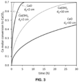
- Figure 3 shows an example of predictions from the shrinking core kinetic model used to solve the reactor model used for Figure 2A .
- These examples are based on a well-known control of the progress of carbonation by Fick's diffusion law in porous Ca-materials of large diameter (i.e., characteristic carbonation lengths> 1 cm) at optimum temperatures of carbonation of 650oC.
- Ca-containing solids having an effective particle diameter or thickness between 10 to 100 mm are able to reach their carbonation conversion close to their maximum (0.5-0.7 at temperatures between 600-700oC) when in contact with a wide range of CO 2 content in the gas, as long as there is gas-solid contact time of between 1-30 hours.
- Figure 4 shows experimental results of carbonation of CaO derived from a single calcination of a typical limestone.
- Figure 4 is also known in the state of the art, but it has been brought here to highlight the fact that in order to achieve a maximum utilization of the sorbent (i.e., maximum of molar conversion of Ca to CaCO 3 ) it is essential that temperatures in the carbonation zone (20) at high temperature are higher than 550o.
- the partial pressure of CO 2 is 0.03 atm at 700oC and hence, CO 2 capture efficiencies will sharply decrease at temperatures exceeding 700oC. Therefore, the operating conditions of the method of this invention should be such as to be able to reach carbonation temperatures in the carbonation zone (20) at high temperature around 650oC ( ⁇ 50oC). The challenge is therefore to find conditions for the method adequate to achieve known optimum carbonation temperature of around 650oC in the carbonation zone (20) at high temperature of Figure 1A .
- the line on the left refers to cases where CaO is the only material in the solids (1) and the line on the right refers to cases where Ca(OH) 2 is the only material in the solids (1).
- Grey bands have been added to both lines to simply cover with a ⁇ 50oC interval the temperatures around 650oC and just ⁇ 10oC interval the temperature around ambient conditions. Although the relationship is not fully linear, it is clear from this analysis when the Ca-containing solids to be carbonated are made of CaO, and the targeted gas is a flue gas with CO 2 volume fraction between 0.02 and 0.1, the inlet temperature of the gas should be higher when the volume fraction of the gas is low and lower when the CO 2 content of the gas is high.
- the results indicate a proportionality rule given by a value of 560oC ⁇ 40oC when the volume fraction is 0.02 and a value of ambient temperature ⁇ 10oC when the volume fraction is 0.09 to 0.1.
- This means that the method of this invention will generate an optimum temperature in the carbonation region of between 600-700oC by simply preheating or cooling the inlet gas to fit the rule given above and in Figure 5 .
- a similar analysis yields a similar proportionality rule, when the solids (1) are Ca(OH) 2 and the inlet gas (3) is a flue gas with CO 2 volume fraction between 0.04 and 0.125, its inlet temperature should be adjusted to follows a proportionality rule given by a value of 550oC ⁇ 30oC when the CO 2 volume fraction is 0.04 and ambient temperature ⁇ 10oC when the volume fraction is 0.125.
- a similar proportionality rules could be achieved when the solids are a mixture of CaO and Ca(OH) 2 .
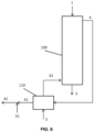
- a preferred embodiment of the method involves the preheating of the inlet gas (3) with the hot gas depleted in CO 2 (4) in a gas-gas heat exchanger (110) and the mixing of the heated product gas (41) with ambient air (31) to reduce the temperature of the product gas (42) as indicated in Figure 6 .
- Figure 5 also indicates that for high CO 2 contents in the gas (CO 2 contents higher than 9%v CO 2 when using CaO and 12.5%v CO 2 when using Ca(OH) 2 ), some kind of cooling below ambient temperature would be needed of the gas entering the reactor (100), in order to compensate for the excess of energy released during carbonation in the carbonation zone (20) and maintain optimum carbonation temperatures in said zone (20). Since cooling of the flue gas from ambient temperature would not be energy efficient and economic, a preferred method for when the inlet gas (3) has a CO 2 volume fraction between 0.1 and 0.25, is further characterized by the spraying of water (56) at the high temperature region located in the central part of the reactor (carbonation zone (20) in Figure 1A ). The Examples below will illustrate the calculation method to of the water flow required to limit the maximum carbonation temperatures to between 600-700oC, preferably around 650oC.
- the method when the gas has a CO 2 volume fraction between 0.1 and 0.25, the method further characterized by the mixing of the flue gas at the inlet gas (3) with ambient air (33) to bring the resulting gas mixture to the CO 2 concentration conditions of described above (see Figure 5 ) to reach autothermal carbonation temperatures between 600-700oC in the carbonation zone (20).
- the physical and thermal properties of solids, and the characteristics of the gas-solid contact mode is similar to the mild solid and gas preheating regions in lime shaft kilns. Therefore, the teachings of such kilns can be applied to choose superficial gas velocities of the gas (3, 4) in the reactor (100) that ensure a sufficient quality in the heat transfer between gas and solids necessary to develop the preheating zones (10, 30).
- the method is further characterized by an inlet gas velocity at the gas entrance of the reactor between 0.5-1 m/s measured at normal conditions, so that both pressure drop and heat transfer between gas and solids remains similar as in shaft kilns.
- Ca-containing solids used in the reactor (100) will be lime rocks produced from the calcination of natural limestone rocks or from recycled carbonated materials, or manufactured from powdered CaO or Ca(OH) 2 in the form of porous pellets or extruded, brick-type or honeycombs (200) with holes or channels (201) as shown in Figure 9 , separated by a solid wall of between 20-30 mm (allowing a depth of the carbonated layer of 10-15 mm in each side of the wall) and a bed porosity (determined in this case by the fraction of free crosssection area occupied by the holes or channels (201)) of between 0.15-0.35 sufficient to moderate the pressure drop in the reactor (100) when the gas has CO 2 concentrations between 2-25%v.
- the possible use of pozzolanic additives for mechanical strength and other additives to enhance porosity and mechanical strength will follow the state of the art of extruding operations of solids in fine particle form.
- All preferred embodiment of this invention are valid for the use in the moving reactor of Ca-containing solids containing an intermediate mixture of CaO and Ca(OH) 2 .
- the purpose of such mixture of CaO and Ca(OH) 2 is to achieve a more adequate average enthalpy of carbonation in the reactor so as to have an additional degree of freedom to reach temperatures for carbonation in the autothermal carbonation zone, and adapt it to the gas treated in the reactor.
- Such average enthalpy of carbonation will indeed range between -69 to -178 kJ/mol Ca depending on the Ca(OH) 2 solid molar ratio varying between 1 and 0.
- the method of this invention requires inlet gas temperatures that are high and very close to optimum carbonation temperature range of 600oC-700oC (see Figure 5 ).
- CO 2 capture efficiencies will be low under such conditions because, even if the gas depleted in CO 2 (4) abandoning the reactor (100) has a concentration of CO 2 at equilibrium with CaO, such concentration will be close to the inlet concentration (note that the equilibrium concentration of CO 2 on CaO is 0.01 at 650oC and 0.03 atm at 700oC).
- the method of this invention will preferably target carbonation temperatures in carbonation zone (20) below 100oC, where it is known in the state of the art that Ca(OH) 2 can achieve high carbonation conversion under the right reaction conditions and gas-solid contact times. Preferred methods are defined below considering a slow motion of solid in such applications, so as to allow the Ca-containing solids to reach a high carbonation degree despite the low CO 2 concentrations in the gas.
- a shrinking core model is observed in the photograph by spraying a phenolphthalein solution (1% weight in ethanol) to dye with colour the unconverted core of Ca(OH) 2 while the region rich in CaCO 3 remains uncolored.
- porous of Ca(OH) 2 in different shapes and forms is part of the state of the art and the method of this invention uses such availability of Ca(OH) 2 materials to optimize the CO 2 capture efficiency when applying the method to gases with low concentrations of CO 2 (below 2%v) and at temperatures below 100oC, as long as the porous Ca(OH) 2 solids has a geometry of the solid such as to expose the external surface of the material to the gas and allow an effective minimum depth of the carbonated layer of 1-3 mm to be developed.
- the solids entering the reactor (1) are porous Ca(OH) 2 pellets, preferably with a surface area higher than 30 m 2 /g
- the gas is a flue gas (3) with volume fraction between 0.005 and 0.04 and temperatures between ambient temperature and 70oC further characterized by water spraying at the entrance of the gas and in the central part of the reactor carbonation region to maintain maximum temperatures below 70oC and relative humidity between 80-100%.
- the gas is air-humidified at ambient temperature, with CO 2 content between 400-500 ppmv, or vitiated air or flue gases at close to ambient temperature with a CO 2 content between 500 to 5000 ppmv and relative humidity between 80-100%, entering the reactor at 5-10 m/s, the solids being contained in the form of extruded honeycombs or bricks, plates or bags with an effective minimum depth of the carbonated layer of 1-3 mm.
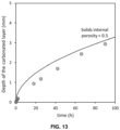
- the preferred intervals adopted in the previous paragraph come from the need to use high superficial gas velocities when targeting relevant capture flows of CO 2 for climate change mitigation purposes (i.e. requiring vast flows of air of at least 50000 Nm 3 /s to capture CO 2 at a rate of 1 Mt CO 2 /y). Since the molar flow of CO 2 is low when feeding to the reactor a given flow of gas (3) with a low concentration of CO 2 , the molar flow of Ca(OH) 2 (1) to be carbonated is proportionally small and the residence time of such Ca(OH) 2 in the carbonation zone (20) can increases inversely proportional to such small solid flow, to reach values as high as 100 hours when targeting depth of the carbonated layer of 1-3 mm (see Figure 13 ).
- the need to moderate the pressure drop in the carbonator reactor (100) requires a sufficient bed porosity (0.6-0.8) and geometry (honeycombs, sheets, plates etc.) of the porous Ca(OH) 2 .
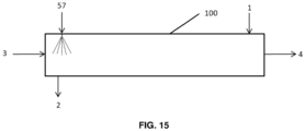
- a horizontal configuration of the reactor (100) may be more convenient to accommodate the long reactors (see EXAMPLE 4), required for air capture, as shown in Figure 15 .
- the previous inlet conditions have been chosen as to translate in the generation of an autothermal high-temperature carbonation zone (20) in the central part of the reactor (100) with a maximum temperature, T max , identical to 650oC considered in the state of the art as optimum for carbonation.
- T max a maximum temperature
- this temperature is lower than the equilibrium temperature for CaCO 3 decomposition at the point with the lowest CO 2 partial pressure in the reactor (i.e., at the exit) when capturing 85% of the CO 2 (which means in this case a CO 2 concentration at the exit of 0.014 being the equilibrium at T Max of 0.01).
- higher capture efficiencies are to be expected, as certain carbonation could occur in the first preheating zone (10) as the equilibrium at T g,out is of only 0.0004 atm.
- the cross-section of the reactor results in 4.08 m 2 .
- the length of carbonation zone provides a final design of the reactor and allows the estimation of the pressure drop. To determine the length of the carbonation reaction zone, it is necessary to establish the time required to reach 90% of carbonation conversion in the CaO, as adopted in the reference design at the average CO 2 concentration found by the solids in their movement countercurrent respect to the gas.
- the diffusivity of CO 2 in air is calculated at 650oC (yielding 1.13 10 -4 m 2 /s) and the porosity of the carbonated layer forming in the exterior of the Ca-containing solids is calculated to be 0.28 from the initial assumed porosity (0.6) and the molar densities of CaCO 3 and CaO.
- the shrinking core model for spheres predicts 8.31 hours to reach 90% of the maximum carbonate conversion in the Ca-containing solids (i.e., an average molar conversion of 0.60 in the Ca-containing solids).
- the volume of the carbonation zone (20) at high temperature is 45.9 m 3 , considering a bed porosity of 0.4, or 11.3 m of reactor reaction zone height.
- the Ergun's equation predicts a pressure drop of just 0.20 atm in such region, at the gas velocity of 3.4 m/s at the inlet temperature conditions of the carbonation reaction region.
- a porosity CaO of 0.46 would require two orders of magnitude longer residence time (and hence reactor volume) to achieve the same objectives of capture than those described in the example. Reducing the activity of the material (i.e., to lead to maximum carbonation conversions below 0.5) would solve the pore plugging limit, but would translate into a less effective use (conversion) of the solids to carbonate, which is not optimum if the method is applied to capture CO 2 from disperse industries requiring transport of the sorbent.
- heat from the gas depleted in CO 2 (4) exiting the reactor (100) is supplied to the incoming flue gas at the inlet gas (3) in a gas-gas heat exchanger (110) as shown in Figure 6 .
- the incoming flue gas temperature is higher than the equilibrium temperature for Ca(OH) 2 decomposition in the flue gas atmosphere (assumed to have 10%v of water vapor), which is 412 oC according to Barin's equation, avoiding the possible re-hydration of the un-carbonated solids coming from the carbonation zone (20) at 650oC (above the Ca(OH) 2 decomposition temperature in water vapor of 519oC).
- the open porosity of the carbonated layer forming in the exterior of the Ca-containing solids is calculated to be 0.57 from the initial assumed porosity (0.6) and the molar densities of CaCO 3 and Ca(OH) 2 .
- This superior carbonated layer porosity for Ca(OH) 2 solids compared to CaO of Example 1 enables for lower residence times or the possibility of more compact bed arrangements, as the solids are extruded, brick-type, honeycombs with depths of the carbonated layer 0.01-0.015 m and reasonable residence times, which is a clear advantage in the use of Ca(OH) 2 solids instead of CaO.
- the method of this invention in particular when using the ability of porous Ca(OH) 2 to extensively carbonate at temperatures below 100oC, allows for deep decarbonisation of gases that have a low content of CO 2 . This can be valuable for many applications, in particular as a "gas polishing" option to remove CO 2 downstream of other capture systems, where approaching very high capture efficiencies ("zero emissions") is not economically viable.
- the CO 2 capture efficiency is of 85%, meaning in this case a CO 2 concentration at the exit of just 0.15%v CO 2 .
- T gas,out and T max of 69oC and 71oC are calculated, respectively.
- this temperature increment would reduce the relative humidity to below 44% at the exit, thus minimizing the carbonation conversion. Therefore, to maintain maximum temperatures below 55oC and relative humidity above 80%, liquid water is sprayed at different locations inside the reactor.
- sprays of 0.015 kg/s at carbonation zone dimensionless heights of 0.43, 0.69, 0.86 and 0.97 are required considering the solids conversion profile in Figure 2A .
- the method of this invention allows for CO 2 capture from air or from vitiated air coming out from buildings or other sources.
- the mild temperatures reached in the carbonation zone when the CO 2 inlet concentration is extremely low allow for very large inventory of solids in the reactor.
- Ca-containing solids of Ca(OH) 2 arranged in the form of extruded, brick-type, honeycombs with 6 mm of thickness (i.e., 3 mm of depth of the carbonated layer) with a solids porosity of 0.6 and a bed porosity of 0.7 (i.e., square voids of 30 mm length) to moderate the pressure drop accounting for the larger flow of atmospheric air to be treated when compared to higher CO 2 contents as in Example 2.
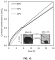
- Ca-containing solids are assumed to have maximum calcium molar conversion of 0.90 at relative humidities (above 80% according to Figures 11 and 12 ).
- T gas,out and T max of just 21oC are calculated respectively ensuring relative humidity above 90% when the CO 2 containing air is saturated in humidity before entering the carbonation reaction zone as shown in Figure 15 .
- T gas,out and T max of just 21oC are calculated respectively ensuring relative humidity above 90% when the CO 2 containing air is saturated in humidity before entering the carbonation reaction zone as shown in Figure 15 .
- Such long residence time can be achieved in a reactor with a cross-section of 6.5 m 2 operated with a gas velocity of 10 m/s at normal conditions.
- the length of such carbonation zone (20) will be 12.7 m and the pressure drop just about 0.024 atm.
Priority Applications (2)
| Application Number | Priority Date | Filing Date | Title |
|---|---|---|---|
| EP21382947.6A EP4169603A1 (de) | 2021-10-21 | 2021-10-21 | Verfahren zur co2-aufnahme unter verwendung eines gegenstromwanderbettreaktors |
| PCT/EP2022/079177 WO2023067046A1 (en) | 2021-10-21 | 2022-10-20 | Co2 capture method using a countercurrent moving bed reactor |
Applications Claiming Priority (1)
| Application Number | Priority Date | Filing Date | Title |
|---|---|---|---|
| EP21382947.6A EP4169603A1 (de) | 2021-10-21 | 2021-10-21 | Verfahren zur co2-aufnahme unter verwendung eines gegenstromwanderbettreaktors |
Publications (1)
| Publication Number | Publication Date |
|---|---|
| EP4169603A1 true EP4169603A1 (de) | 2023-04-26 |
Family
ID=78516750
Family Applications (1)
| Application Number | Title | Priority Date | Filing Date |
|---|---|---|---|
| EP21382947.6A Withdrawn EP4169603A1 (de) | 2021-10-21 | 2021-10-21 | Verfahren zur co2-aufnahme unter verwendung eines gegenstromwanderbettreaktors |
Country Status (2)
| Country | Link |
|---|---|
| EP (1) | EP4169603A1 (de) |
| WO (1) | WO2023067046A1 (de) |
Citations (7)
| Publication number | Priority date | Publication date | Assignee | Title |
|---|---|---|---|---|
| DE869043C (de) * | 1939-01-03 | 1953-03-02 | Ruhrchemie Ag | Verfahren zur Entfernung von Kohlensaeure aus Gasen mittels Kalk |
| US5509362A (en) | 1992-12-11 | 1996-04-23 | Energy And Environmental Research Corporation | Method and apparatus for unmixed combustion as an alternative to fire |
| US20050036932A1 (en) * | 1998-10-29 | 2005-02-17 | Nkk Corporation | Method for reducing exhaust carbon dioxide |
| US20120164032A1 (en) | 2009-09-18 | 2012-06-28 | Wormser Energy Solutions, Inc. | Systems, devices and methods for calcium looping |
| US8226917B2 (en) | 2003-02-06 | 2012-07-24 | The Ohio State University | Separation of carbon dioxide from gas mixtures by calcium based reaction separation |
| US20200016537A1 (en) * | 2017-03-08 | 2020-01-16 | Fjell Biodry As | Gas capture system |
| US20200263580A1 (en) * | 2019-02-14 | 2020-08-20 | Primarine GmbH | Method and Device Intended to Purify Sulphur Oxide Containing Exhaust Gas from Internal Combustion Engines by Means of a Multi-stage Adsorption Method |
-
2021
- 2021-10-21 EP EP21382947.6A patent/EP4169603A1/de not_active Withdrawn
-
2022
- 2022-10-20 WO PCT/EP2022/079177 patent/WO2023067046A1/en unknown
Patent Citations (7)
| Publication number | Priority date | Publication date | Assignee | Title |
|---|---|---|---|---|
| DE869043C (de) * | 1939-01-03 | 1953-03-02 | Ruhrchemie Ag | Verfahren zur Entfernung von Kohlensaeure aus Gasen mittels Kalk |
| US5509362A (en) | 1992-12-11 | 1996-04-23 | Energy And Environmental Research Corporation | Method and apparatus for unmixed combustion as an alternative to fire |
| US20050036932A1 (en) * | 1998-10-29 | 2005-02-17 | Nkk Corporation | Method for reducing exhaust carbon dioxide |
| US8226917B2 (en) | 2003-02-06 | 2012-07-24 | The Ohio State University | Separation of carbon dioxide from gas mixtures by calcium based reaction separation |
| US20120164032A1 (en) | 2009-09-18 | 2012-06-28 | Wormser Energy Solutions, Inc. | Systems, devices and methods for calcium looping |
| US20200016537A1 (en) * | 2017-03-08 | 2020-01-16 | Fjell Biodry As | Gas capture system |
| US20200263580A1 (en) * | 2019-02-14 | 2020-08-20 | Primarine GmbH | Method and Device Intended to Purify Sulphur Oxide Containing Exhaust Gas from Internal Combustion Engines by Means of a Multi-stage Adsorption Method |
Non-Patent Citations (6)
| Title |
|---|
| ABANADES: "An air C0 capture system based on the passive carbonation of large Ca(OH) structures", SUST. ENERG. & FUELS, vol. 4, 2020, pages 3409 - 3417 |
| BERUTO ET AL.: "Liquid-like H 0 adsorption layers to catalyze the Ca(OH) /C0 solid-gas reaction and to form a non-protective solid iroduct layer at 20°C", J. EUR. CERAM. SOC., vol. 20, no. 4, 2000, pages 497 - 503, XP004187939, DOI: 10.1016/S0955-2219(99)00185-5 |
| H. PIRINGER: "Lime Shaft Kilns", ENERGY PROCEDIA, vol. 120, 2017, pages 75 - 95, XP085197646, DOI: 10.1016/j.egypro.2017.07.156 |
| LISBONA ET AL.: "Technoeconomic feasibility study of cement plants as reference facilities for centralized C0 capture in industrial sites", 15TH INTERNATIONAL CONFERENCE ON GREENHOUSE GAS CONTROL TECHNOLOGIES, GHGT-15, 15 March 2021 (2021-03-15) |
| MONDINO: "Moving bed temperature swing adsorption for C02 capture from a natural gas combined cycle power plant", GREENHOUSE GAS CONTROL, vol. 85, 2019, pages 58 - 70 |
| Y.A. CRIADO ET AL.: "Effect of the carbonation temperature on the C0 carrying capacity of CaO", IND. ENG. CHEM. RES., vol. 57, 2018, pages 12595 - 12599 |
Also Published As
| Publication number | Publication date |
|---|---|
| WO2023067046A1 (en) | 2023-04-27 |
Similar Documents
| Publication | Publication Date | Title |
|---|---|---|
| US10668443B2 (en) | Curing systems for materials that consume carbon dioxide and method of use thereof | |
| Kierzkowska et al. | CaO‐based CO2 sorbents: from fundamentals to the development of new, highly effective materials | |
| Abanades et al. | Capture of CO2 from combustion gases in a fluidized bed of CaO | |
| JP2003212510A (ja) | 燃料改質方法およびそのシステム | |
| AU2007233570A1 (en) | System and method for the calcination of minerals | |
| EP3099459A2 (de) | Belüftete verbundmaterialien, verfahren zur herstellung davon und verwendungen davon | |
| Sánchez-Jiménez et al. | Influence of ball milling on CaO crystal growth during limestone and dolomite calcination: effect on CO2 capture at calcium looping conditions | |
| Yin et al. | Calcium looping for CO2 capture at a constant high temperature | |
| CN87103687A (zh) | 一种将含硫化合物氧化成硫的催化剂及方法和制备该催化剂的制备方法 | |
| Wang et al. | Steam hydration of calcium oxide for solid sorbent based CO2 capture: effects of sintering and fluidized bed reactor behavior | |
| EP4169603A1 (de) | Verfahren zur co2-aufnahme unter verwendung eines gegenstromwanderbettreaktors | |
| Ghorbaei et al. | Carbonation reaction of strontium oxide for thermochemical energy storage and CO2 removal applications: Kinetic study and reactor performance prediction | |
| García-Lario et al. | Evaluation of process variables on the performance of sorption enhanced methane reforming | |
| Alonso et al. | CO2 carrying capacities of cement raw meals in calcium looping systems | |
| Abanades et al. | Countercurrent moving bed carbonator for CO2 capture in decoupled calcium looping systems | |
| Symonds et al. | The effect of HCl and steam on cyclic CO2 capture performance in calcium looping systems | |
| US20160059179A1 (en) | Carbon dioxide removal system | |
| EP2724771B1 (de) | Vorrichtung und verfahren zur co2-abscheidung durch cao-karbonisierung und zur bewahrung der sorptionswirkung | |
| Loutzenhiser et al. | CO2 reduction with Zn particles in a packed‐bed reactor | |
| Abanades García et al. | CO2 capture method using a countercurrent moving bed reactor | |
| Green et al. | Capture of carbon dioxide from flue gas using solid regenerable sorbents | |
| Fang et al. | CO 2 capture from flue gases using a fluidized bed reactor with limestone | |
| Johnsen | Sorption-enhanced steam methane reforming in fluidized bed reactors | |
| JP7041443B1 (ja) | 反応熱の除熱に吸熱反応を用いるメタン化反応装置および吸熱材の再生処理プロセス | |
| Díaz et al. | The Ca-Cu looping process using natural CO2 sorbents in a packed bed: Operation strategies to accommodate activity decay |
Legal Events
| Date | Code | Title | Description |
|---|---|---|---|
| PUAI | Public reference made under article 153(3) epc to a published international application that has entered the european phase |
Free format text: ORIGINAL CODE: 0009012 |
|
| STAA | Information on the status of an ep patent application or granted ep patent |
Free format text: STATUS: THE APPLICATION HAS BEEN PUBLISHED |
|
| AK | Designated contracting states |
Kind code of ref document: A1 Designated state(s): AL AT BE BG CH CY CZ DE DK EE ES FI FR GB GR HR HU IE IS IT LI LT LU LV MC MK MT NL NO PL PT RO RS SE SI SK SM TR |
|
| STAA | Information on the status of an ep patent application or granted ep patent |
Free format text: STATUS: THE APPLICATION IS DEEMED TO BE WITHDRAWN |
|
| 18D | Application deemed to be withdrawn |
Effective date: 20231027 |