EP4169547B1 - Verbesserte verabreichungsvorrichtung - Google Patents
Verbesserte verabreichungsvorrichtung Download PDFInfo
- Publication number
- EP4169547B1 EP4169547B1 EP21204488.7A EP21204488A EP4169547B1 EP 4169547 B1 EP4169547 B1 EP 4169547B1 EP 21204488 A EP21204488 A EP 21204488A EP 4169547 B1 EP4169547 B1 EP 4169547B1
- Authority
- EP
- European Patent Office
- Prior art keywords
- housing
- piston rod
- administration device
- seal
- aperture
- Prior art date
- Legal status (The legal status is an assumption and is not a legal conclusion. Google has not performed a legal analysis and makes no representation as to the accuracy of the status listed.)
- Active
Links
Images





Classifications
-
- A—HUMAN NECESSITIES
- A61—MEDICAL OR VETERINARY SCIENCE; HYGIENE
- A61M—DEVICES FOR INTRODUCING MEDIA INTO, OR ONTO, THE BODY; DEVICES FOR TRANSDUCING BODY MEDIA OR FOR TAKING MEDIA FROM THE BODY; DEVICES FOR PRODUCING OR ENDING SLEEP OR STUPOR
- A61M5/00—Devices for bringing media into the body in a subcutaneous, intra-vascular or intramuscular way; Accessories therefor, e.g. filling or cleaning devices, arm-rests
- A61M5/14—Infusion devices, e.g. infusing by gravity; Blood infusion; Accessories therefor
- A61M5/142—Pressure infusion, e.g. using pumps
- A61M5/14244—Pressure infusion, e.g. using pumps adapted to be carried by the patient, e.g. portable on the body
- A61M5/14248—Pressure infusion, e.g. using pumps adapted to be carried by the patient, e.g. portable on the body of the skin patch type
-
- A—HUMAN NECESSITIES
- A61—MEDICAL OR VETERINARY SCIENCE; HYGIENE
- A61M—DEVICES FOR INTRODUCING MEDIA INTO, OR ONTO, THE BODY; DEVICES FOR TRANSDUCING BODY MEDIA OR FOR TAKING MEDIA FROM THE BODY; DEVICES FOR PRODUCING OR ENDING SLEEP OR STUPOR
- A61M5/00—Devices for bringing media into the body in a subcutaneous, intra-vascular or intramuscular way; Accessories therefor, e.g. filling or cleaning devices, arm-rests
- A61M5/14—Infusion devices, e.g. infusing by gravity; Blood infusion; Accessories therefor
- A61M5/142—Pressure infusion, e.g. using pumps
- A61M5/14212—Pumping with an aspiration and an expulsion action
- A61M5/14216—Reciprocating piston type
-
- A—HUMAN NECESSITIES
- A61—MEDICAL OR VETERINARY SCIENCE; HYGIENE
- A61M—DEVICES FOR INTRODUCING MEDIA INTO, OR ONTO, THE BODY; DEVICES FOR TRANSDUCING BODY MEDIA OR FOR TAKING MEDIA FROM THE BODY; DEVICES FOR PRODUCING OR ENDING SLEEP OR STUPOR
- A61M5/00—Devices for bringing media into the body in a subcutaneous, intra-vascular or intramuscular way; Accessories therefor, e.g. filling or cleaning devices, arm-rests
- A61M5/178—Syringes
- A61M5/31—Details
- A61M5/315—Pistons; Piston-rods; Guiding, blocking or restricting the movement of the rod or piston; Appliances on the rod for facilitating dosing ; Dosing mechanisms
- A61M5/31511—Piston or piston-rod constructions, e.g. connection of piston with piston-rod
- A61M5/31513—Piston constructions to improve sealing or sliding
-
- A—HUMAN NECESSITIES
- A61—MEDICAL OR VETERINARY SCIENCE; HYGIENE
- A61M—DEVICES FOR INTRODUCING MEDIA INTO, OR ONTO, THE BODY; DEVICES FOR TRANSDUCING BODY MEDIA OR FOR TAKING MEDIA FROM THE BODY; DEVICES FOR PRODUCING OR ENDING SLEEP OR STUPOR
- A61M5/00—Devices for bringing media into the body in a subcutaneous, intra-vascular or intramuscular way; Accessories therefor, e.g. filling or cleaning devices, arm-rests
- A61M5/14—Infusion devices, e.g. infusing by gravity; Blood infusion; Accessories therefor
- A61M5/142—Pressure infusion, e.g. using pumps
- A61M5/14244—Pressure infusion, e.g. using pumps adapted to be carried by the patient, e.g. portable on the body
- A61M5/14248—Pressure infusion, e.g. using pumps adapted to be carried by the patient, e.g. portable on the body of the skin patch type
- A61M2005/14252—Pressure infusion, e.g. using pumps adapted to be carried by the patient, e.g. portable on the body of the skin patch type with needle insertion means
-
- A—HUMAN NECESSITIES
- A61—MEDICAL OR VETERINARY SCIENCE; HYGIENE
- A61M—DEVICES FOR INTRODUCING MEDIA INTO, OR ONTO, THE BODY; DEVICES FOR TRANSDUCING BODY MEDIA OR FOR TAKING MEDIA FROM THE BODY; DEVICES FOR PRODUCING OR ENDING SLEEP OR STUPOR
- A61M5/00—Devices for bringing media into the body in a subcutaneous, intra-vascular or intramuscular way; Accessories therefor, e.g. filling or cleaning devices, arm-rests
- A61M5/14—Infusion devices, e.g. infusing by gravity; Blood infusion; Accessories therefor
- A61M5/142—Pressure infusion, e.g. using pumps
- A61M5/14244—Pressure infusion, e.g. using pumps adapted to be carried by the patient, e.g. portable on the body
- A61M2005/14268—Pressure infusion, e.g. using pumps adapted to be carried by the patient, e.g. portable on the body with a reusable and a disposable component
-
- A—HUMAN NECESSITIES
- A61—MEDICAL OR VETERINARY SCIENCE; HYGIENE
- A61M—DEVICES FOR INTRODUCING MEDIA INTO, OR ONTO, THE BODY; DEVICES FOR TRANSDUCING BODY MEDIA OR FOR TAKING MEDIA FROM THE BODY; DEVICES FOR PRODUCING OR ENDING SLEEP OR STUPOR
- A61M5/00—Devices for bringing media into the body in a subcutaneous, intra-vascular or intramuscular way; Accessories therefor, e.g. filling or cleaning devices, arm-rests
- A61M5/14—Infusion devices, e.g. infusing by gravity; Blood infusion; Accessories therefor
- A61M5/1413—Modular systems comprising interconnecting elements
-
- A—HUMAN NECESSITIES
- A61—MEDICAL OR VETERINARY SCIENCE; HYGIENE
- A61M—DEVICES FOR INTRODUCING MEDIA INTO, OR ONTO, THE BODY; DEVICES FOR TRANSDUCING BODY MEDIA OR FOR TAKING MEDIA FROM THE BODY; DEVICES FOR PRODUCING OR ENDING SLEEP OR STUPOR
- A61M5/00—Devices for bringing media into the body in a subcutaneous, intra-vascular or intramuscular way; Accessories therefor, e.g. filling or cleaning devices, arm-rests
- A61M5/14—Infusion devices, e.g. infusing by gravity; Blood infusion; Accessories therefor
- A61M5/142—Pressure infusion, e.g. using pumps
- A61M5/145—Pressure infusion, e.g. using pumps using pressurised reservoirs, e.g. pressurised by means of pistons
- A61M5/1452—Pressure infusion, e.g. using pumps using pressurised reservoirs, e.g. pressurised by means of pistons pressurised by means of pistons
- A61M5/14566—Pressure infusion, e.g. using pumps using pressurised reservoirs, e.g. pressurised by means of pistons pressurised by means of pistons with a replaceable reservoir for receiving a piston rod of the pump
Definitions
- the present invention relates to the field of administration devices and administration apparatus for fluid medications, in particular infusion or injection devices.
- the present invention relates to administration devices with movable piston rods.
- the applicant's Ypsopump is known from the state of the art.
- the Ypsopump is a conventional insulin pump with which insulin can be administered from a standard cartridge.
- the Figures 1 to 3 show the entire Ypsopump, or rather areas of it.
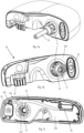
- Figure 1 shows the Ypsopump p1 in a perspective view. From the outside you can see the housing p5 with the viewing window p6, through which the condition of the carpule p2 (see Figure 2 ) can be controlled. Also visible is the control button p10 and the display p20, which is The p20 display is a touch display. Also visible are the infusion set adapter p30 and the infusion set tube p31.
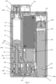
- FIG. 2 shows a cross-section of the Ypsopump p1 and the infusion set adapter p30.
- the functionality of the Ypsopump p1 can be briefly explained.
- the carpule p2 has an open end, which is closed by the movably mounted stopper p4. At its second end, the carpule p2 is closed with a septum p3.
- the cannula p30a of the infusion set adapter p30 can pierce this septum, allowing medication (insulin) to pass through the cannula p30a into the infusion set tube p31 and ultimately be administered subcutaneously to the patient.
- the stopper p4 is moved by the piston rod p52.
- FIG 2 shows a full carpule p2 and the piston rod p52 is completely retracted.
- the piston rod p52 is driven by the motor p40, which is connected to the piston rod p52 via the gear p45 and the drive sleeve 51.
- the piston rod p52 is connected to the drive housing p50 via the anti-twist device p50a in a way that is secured against twisting but can be moved axially. Since the drive housing p50 is firmly arranged in the housing p5, the piston rod p52 is also secured against twisting relative to the housing p5.
- the drive sleeve p51 has a thread on its inside p52b, which is threadedly connected to the proximal end of the piston rod p52. If the drive sleeve p51 is rotated on its axis, the piston rod p52 is moved proximally or distally due to the existing anti-twist device (see above).
- Figure 2 further shows the battery compartment p91 with the battery p90, the negative terminal p93 and the positive terminal p92.
- the positive terminal p92 is part of the battery compartment cover p7.
- Figure 2 further symbolically shows the electronics p80.
- the infusion set adapter p30 holds the carpule p2 in the infusion pump p1 and is fixed in the Ypsopump p1 via a bayonet lock. However, the infusion set adapter does not seal the carpule compartment p9 watertight.
- p54 and p60 protect on the drive side/carpule compartment.
- P92a and p93 protect on the battery compartment side.
- the plain bearing between the piston rod p52 and the anti-twist device p50a is also not liquid-tight, so that the area between the piston rod p52 and the rotating sleeve p51 could be contaminated - potential for further improvements.
- longitudinal grooves p52a are arranged to prevent rotation of the piston rod p52, into which the rotation lock p50a (cam) engages.
- This groove/cam The anti-twisting device makes it difficult to position an elastic sealing element in this area, which also functions as a bearing, which really seals and at the same time allows a sliding movement of the piston rod p52 within the pump p1.
- piston rods with a square cross-section (square, rectangle) are also known to prevent the piston rod from twisting.
- a sealing problem arises because the contact pressure of a seal arranged around the cross-section reaches its maximum in the corners and is weaker along the edges, so that the risk of leaks is considerable.
- product in the present context includes any flowable medical formulation suitable for controlled administration by means of a cannula or hollow needle into subcutaneous or intramuscular tissue, for example a liquid, a solution, a gel or a fine suspension containing one or more medicinal active ingredients.
- a medicine can therefore be a composition with a single active ingredient or a premixed or co-formulated composition with several active ingredients from a single container.
- the term includes in particular medicinal products such as peptides (e.g.
- insulins insulin-containing medicines, GLP 1-containing and derived or analogous preparations
- proteins and hormones proteins and hormones
- biologically derived or active ingredients active ingredients based on hormones or genes
- nutritional formulations enzymes and other substances in both solid (suspended) and liquid form.
- the term also includes polysaccharides, vaccines, DNA or RNA or oligonucleotides, antibodies or parts of antibodies as well as suitable base, auxiliary and carrier substances.
- distal refers to a side or direction directed towards the front, piercing end of the administration device or towards the tip of the injection needle.
- proximal refers to a side or direction directed towards the rear end of the administration device opposite the piercing end.
- administration device and “administration apparatus” are used synonymously in this document.
- the administration device can be an injection device, for example an injection pen, or an infusion device.
- Infusion devices include in particular insulin pumps and patch pumps, and injection devices also include auto-injectors, pens for automatic and repeated dispensing of individually adjustable doses (so-called autopens) and patch injectors.
- the administration devices can be monolithic or modular. What all devices according to the invention have in common is that there are areas of the administration device that should be protected from liquid. These can be mechanical, electrical, electronic, magnetic, electromagnetic components, assemblies or combinations thereof.
- An administration device comprises a housing, which in turn can consist of several modules, but does not have to.
- the modules can represent smaller housings in themselves.
- a reservoir can be arranged at least partially inside the housing.
- the distal end of the reservoir through which medication is delivered can be located outside the housing.
- the reservoir comprises an internal volume which can be reduced in size for delivery of medication.
- the reservoir can be a so-called carpule in the broader sense, which has a closed end with a septum, whereby the septum can be pierced using a cannula.
- a cannula for example, it can be the cannula of an injection needle or the cannula of an infusion set adapter.
- the carpule is open at its other end, with a movable plug closing the open end. This creates an internal volume in the carpule. This volume can be increased or reduced by moving the plug.
- Various carpule materials are known to the expert, made of glass or plastic, with a round or oval cross-section, or with a linear axis or a curved axis (e.g. toroidal).
- the reservoir can be a bag that is squeezed when medication is administered.
- the administration device further comprises a drive device.
- the drive device is arranged at least partially in the housing or a module of the housing.
- the drive device serves to expel medication from the reservoir if a reservoir is present.
- the drive device comprises a drive.
- the drive serves as a source of mechanical energy.
- the drive can be a motor, in particular an electric motor.
- the administration device is an injection device, the drive can be an arrangement of one or more springs.
- the task of the drive is to move a piston rod that is also movably mounted at least partially in the housing or partially in one or more modules.
- the piston rod is mounted directly or indirectly in the housing or a module so that it can be moved but not rotated.
- the drive can be coupled directly or indirectly to the piston rod.
- a gear can be arranged between the drive and the motor, which converts the motor movement (usually a rotating, driven axis) into a displacement movement of the piston rod.
- the coupling between the drive (direct or indirect) and the piston rod can be achieved, for example, via a threaded connection between the drive and the piston rod.
- the piston rod can have an internal thread that is in threaded engagement with a threaded rod or spindle of the drive. A rotation of the threaded rod or spindle causes a displacement of the piston rod due to the non-rotatability of the piston rod.
- the threaded rod or spindle is advantageously the output element of a gear between a motor and the piston rod.
- the piston rod can, for example, move a cartridge stopper or compress a bag.
- an opening is provided in an inner wall of the housing or a wall of a module of the housing, on or in which one or more anti-twist elements are present.
- the piston rod is guided through this opening and is slidably mounted in it.
- the opening can be a polygonal opening through which the piston rod is guided (through-passage), and the polygonal shape approximately reflects the cross-section of the piston rod.
- anti-twist protection can be achieved analogously to the variant described above.
- anti-twist protection can be achieved using additional elements that are firmly arranged on the opening.
- the wall in the area of the opening can also be mechanically reinforced in order to additionally to be able to absorb forces acting on the wall. This can be done by increasing the wall thickness, by rib-like reinforcements, or by other means known to those skilled in the art.
- the opening is further provided with a seal which seals the area between the opening and the piston rod, so that when the piston rod is guided through the opening, no liquid can pass from one side of the wall to the other through the opening.
- the seal is made of a material that is at least elastically deformable and can seal the circumference of the piston rod at least via a linear contact.
- the contact between the seal and the piston rod is not only linear, but also extends along the piston rod axis, so that a sealing surface is created.
- the piston rod can be moved (advantageously in both directions for reusable devices).
- the piston rod has a special cross-sectional shape, at least over the axial area that is displaced by the opening, which enables improved sealing.
- the shape of the cross-section corresponds to a non-trivial orbiform curve.
- Wikipedia the understandable definition from Wikipedia is reproduced here (https://de.wikipedia.org/wiki/Gleichdick): "A constant thickness or a region of constant width is a figure that is the same thickness or has the same width everywhere. The edge of such a figure is called a curve of constant width or orbiform ("circular").
- the width of a curve is defined as the distance between two parallel lines that touch the curve on opposite sides. These lines are called support lines. Curves of constant width are those curves where the distance between these lines is always the same, regardless of where in the figure the lines touch.”
- the simplest, nota bene trivial, constant is the circle.
- the simplest non-trivial constant which represents a cross-sectional shape according to the invention, is the so-called Reuleaux triangle or circular arc triangle r1, as it is in Figure 4a shown.
- Figure 4a further shows the equilateral triangle r2, which is used to construct Reuleaux triangle r1, as well as the radius R, which corresponds to the thickness of the equilateral triangle and the side length of the triangle.
- Figure 4d shows a triangular constant with rounded corners r5
- Figures 4b and 4c show the construction of the same.
- the corners are rounded with the radius r4, where the size of the radius
- corresponds to the additional thickness applied to the entire constant thickness, so that the resulting thickness of the constant thickness can be calculated as R' R + 2*
- r3 corresponds to the radius R plus
- the size of the radius r3 can take on any size
- the material for the second component is an injection-moldable, in particular thermoplastic, polyurethane or polyamide.
- it can also be a thermoplastic elastomer in general.
- the second component consists of silicone, for example a silicone made of two components, which hardens in the injection molding device.
- the administration device is an infusion pump in the style of the Ypsopump described above.
- the infusion pump can be a modular pump, which consists, for example, of a reusable module with electronics and drive and a disposable module.
- the disposable module can then accommodate, for example, the medication reservoir and, advantageously, a energy source.
- the infusion pump can be a so-called plaster or patch pump, which is stuck to the skin of the person using it, in particular it can be a modular patch pump.
- the administration device is an injection device.
- the injection device can in particular be in the shape of a pen or pencil.
- the injection device can be a so-called patch injector, which can be stuck to the skin of the person using it for a single injection of medication.
- the injection device can be a pen-shaped auto-injector, such as the one marketed by the applicant as the Ypsomate.
- the injection device is an injection pen, with which several doses can be dispensed automatically, such as the well-known ServoPen from the applicant.
- the injection devices can, for example, contain electronics that must be protected.
- FIGS. 1 to 3 show previously known state of the art according to the background explanations.
- Figures 4 and 5 show details of the different forms of the equidistant.
- the Figures 6 to 10 show an embodiment according to the invention.
- Figure 11 shows an alternative design.
- FIG. 6a shows an administration device according to the invention in the form of the plaster or patch pump 1.
- the patch pump 1 is constructed very similarly to that in the European patent application EP20181599.0 which is hereby incorporated by reference in its entirety into This document is adopted. Details on the basic technology of patch pump 1 can be found in the application EP20181599.0 can be taken directly and clearly.
- Patch pump 1 is, as in the Figures 6b and 6c shown, has a modular structure and comprises a pump module 2 and a reservoir module 3, which can be detachably connected to one another via the bayonet catch with parts 10 on the reservoir module 3 and 11 on the pump module. If the reservoir module 3 and pump module 2 are connected to one another via the bayonet catch, the detent spring 11a of the pump module 2 engages behind the detent 10a of the reservoir module 2 so that the two modules cannot accidentally come apart.
- the pump module 2 is reusable and comprises the pump electronics (not shown) and the drive (not shown, with motor, gear, transmission elements) as well as the piston rod 30 which is movably mounted in the pump module 2.
- the pump module 2 can also comprise an energy source in the form of a repeatedly rechargeable battery.
- the reservoir module 3 comprises the reservoir, an energy source in the form of, for example, a battery and an infusion line, which can guide the medication to be administered from the reservoir into the tissue.
- the aforementioned battery can be used to charge the rechargeable battery (or an analog energy storage device, e.g. a capacitor).
- the reservoir (not shown) is typically roughly in the shape of a carpule, with a movable plug (not shown) stored in the reservoir. By moving the plug in the reservoir, the volume in the reservoir can be reduced or increased.
- the plug in the reservoir can be moved by an axial movement of the piston rod. In this case, a movement of the piston rod 30 into the reservoir module 3 would typically be carried out, resulting in a reduction in the volume in the reservoir and, finally, a release of medication through the infusion line into the tissue of the person using it.
- the piston rod 30 can be moved, in particular partially moved out of the pump module 2.
- the pump module 2 comprises a housing 12 and a front element 20.
- On the front element 20, as shown for example in the Figures 6b and 7a various elements are arranged. These are the bayonet lock 11 (pump module component, which is arranged around the opening 21, in the shape of a nozzle), the opening 21 for the piston rod 30, the plug for the electrical connector 23 and the reset button 24 - other or further elements would be possible.
- the front element has a front side 20a and a back side 20b, see Figures 7b and 7c .
- the piston rod 30 is guided in the opening 21, it Figures 7a to 7c .
- the piston rod 30 has a cross-section which has the shape of a triangular equal-diameter with rounded corners.
- the opening 21 has a shape that corresponds approximately to the negative of the constant thickness, so that the piston rod 30 can be moved through the opening 21, but cannot rotate about the axis of the piston rod 30.
- the piston rod 30 is thus mounted in the opening 21 so that it can move but is secured against rotation.
- the opening 21 is reinforced by the ribs 21a, whereby the ribs 21a with their end faces 21b can also guide the piston rod 30 in particular (see in particular the Figures 8a to 9b ).
- the seal 22 is arranged on the front side 20a of the front element 20.
- the seal 22 follows the shape of the constant diameter of the cross section of the piston rod 30.
- the opening of the seal 22 is smaller in the undeformed state than the cross section of the piston rod 30. If the piston rod 30 is pushed through the opening of the seal 22, this opening is expanded.
- the seal is therefore made of a deformable material, in particular an elastomer. The seal can thus prevent liquid from penetrating the interface between the piston rod 30 and the seal 22 (and thus the opening 21).
- the seal 22 could actually be glued to the nozzle of the bayonet catch 11.
- the front element 20 is a 2-component injection-molded part, which allows the wall of the front element 20 and the seal 22 to be produced as one part with a tight adhesive bond.
- the front element 20 consists of a component 26, called front element plate 26, and the sealing ensemble 25.
- the sealing ensemble is made of a softer material (in particular elastomer material) than the front element plate 26, which must guide the piston rod 30, among other things.
- the front element plate 26 must therefore have a certain rigidity and strength. During production, the front element plate is injected first and then the sealing ensemble 25 in the same injection mold.
- the sealing ensemble 25 includes not only the seal 22, but also the seal 24 for the reset button.
- the actual reset switch is not shown in the drawings; it is used to reset settings in the pump electronics of the pump module 2, to delete the corresponding memory and/or to restart the electronics of the pump module 2 (for example by a brief power interruption).
- Figure 10d shows a vertical section through the front element 20 in the area of the reset button, specifically the seal 24.
- the seal is a structured membrane, whereby the operating element 24a of the seal 24 does not protrude from the surrounding wall of the front element 20 in the direction of the front side 20a, but lies flat or recessed in order to prevent accidental actuation of the reset button.
- holding elements 20d are provided at the transition between the seal 24 and the front element 20. (see Figures 10b and 10d ) is arranged on the front element (a chemical bond already advantageously exists).
- the sealing assembly 26 further comprises the seal 28 for the electrical contacts of the electrical connector 23.
- the seal 28 has a geometric undersize compared to the contacts designed as pins, which creates a radial pressure of the seal on the pins. It is intended to prevent liquid from penetrating along the electrical contacts into the interior of the pump module 2.
- Figure 10e shows a vertical section through the front element 20 in the area of the connector 23, with the front side of the front element 20 being on the right in the figure.
- the seals are connected to one another via the arms 25a, 25b and 25b. Corresponding channels are provided for this purpose on the rear side of the front element plate (26). In this embodiment, all of the seals are molded via the eyelet 25d. In this way, the front plate 20 with seals can be elegantly manufactured in one injection molding process.
- Figure 11 shows an alternative design of the front element 20, namely the front element 20' with a modified seal 22 ⁇ .
- the opening is circular and not modeled on the equal thickness of the piston rod 30.
- a functioning sealing function of the seal 22 is nevertheless possible because the shape of the equal thickness allows a more homogeneous stress distribution in the seal, so that, for example, in the area of the corners relative to the edges, no excessive stress difference arises, as would arise with an equilateral triangle as the cross-section for the piston rod. Nevertheless, the shape of the equal thickness allows a secure anti-twisting protection, as described.
Landscapes
- Health & Medical Sciences (AREA)
- Heart & Thoracic Surgery (AREA)
- Vascular Medicine (AREA)
- Engineering & Computer Science (AREA)
- Anesthesiology (AREA)
- Biomedical Technology (AREA)
- Hematology (AREA)
- Life Sciences & Earth Sciences (AREA)
- Animal Behavior & Ethology (AREA)
- General Health & Medical Sciences (AREA)
- Public Health (AREA)
- Veterinary Medicine (AREA)
- Dermatology (AREA)
- Infusion, Injection, And Reservoir Apparatuses (AREA)
Description
- Die vorliegende Erfindung betrifft das Gebiet der Verabreichungsgeräte und Verabreichungsvorrichtungen für fluide Medikamente, insbesondere Infusions- oder Injektionsgeräte. Speziell betrifft die vorliegende Erfindung Verabreichungsgeräte mit beweglichen Kolbenstangen.
- Verabreichungsgeräte für fluide, insbesondere flüssige Medikamente sind in einer grossen Vielfalt bekannt. Von einfachen Einwegspritzen über Injektionspens bis hin zu Infusionsgeräten mit ausgeklügelten Funktionen. Insbesondere bei wiederverwendbaren Verabreichungsgeräten ist es wichtig für die Langlebigkeit der Geräte, wichtige Teile wie Antrieb oder Elektronik vor eindringender Flüssigkeit zu schützen.
- Das Problem wird folgend und beispielhaft anhand von Insulinpumpen erläutert. Das Problem tritt jedoch auch bei wiederverwendbaren Injektionspens und anderen Verabreichungsgeräten auf, weshalb die folgenden Erläuterungen keinesfalls einschränkend ausgelegt werden sollen.
- Aus dem Stand der Technik ist beispielsweise die Ypsopump der Anmelderin bekannt. Bei der Ypsopump handelt es sich um eine konventionelle Insulinpumpe, mit welcher Insulin aus einer Standard-Karpule verabreicht werden kann. Die
Figuren 1 bis 3 zeigen die ganze Ypsopump, respektive Bereiche daraus. - Die
Figuren 1 bis 3 zeigen vorbekannten Stand der Technik gemäss den Erläuterungen zum Hintergrund. Sie sind derEP 3110475 B1 entnommen, welche hiermit durch Referenz vollständig in den vorliegenden Dokumenten aufgenommen ist. -
Figur 1 zeigt die Ypsopump p1 in einer perspektivischen Ansicht. Von aussen zu sehen ist das Gehäuse p5 mit dem Sichtfenster p6, durch welches der Zustand der Karpule p2 (siehe dazuFigur 2 ) kontrolliert werden kann. Weiter zu sehen ist Bedienknopf p10 und das Display p20, wobei es sich beim Display p20 um ein Touch-Display handelt. Weiter zu sehen sind der Infusionssetadapter p30 und der Infusionssetschlauch p31. -
Figur 2 zeigt einen Schnitt durch die Ypsopump p1 und den Infusionssetadapter p30. AnhandFigur 2 kann die Funktionsweise der Ypsopump p1 kurz erläutert werden. Die Karpule p2 hat ein offenes Ende, welches durch den beweglich gelagerten Stopfen p4 verschlossen wird. An ihrem zweiten Ende ist die Karpule p2 mit einem Septum p3 verschlossen. Die Kanüle p30a des Infusionssetadapters p30 kann dieses Septum durchstechen, wodurch Medikament (Insulin) durch die Kanüle p30a in den Infusionssetschlauch p31 gelangen und in letzter Konsequenz subkutan dem oder der Patientin verabreicht werden kann. Der Stopfen p4 wird durch die Kolbenstange p52 bewegt.Figur 2 zeigt dabei eine volle Karpule p2 und entsprechend die Kolbenstange p52 vollständig zurückgezogen. Angetrieben wird die Kolbenstange p52 durch den Motor p40, welcher über das Getriebe p45 und die Antriebshülse 51 mit der Kolbenstange p52 verbunden ist. Die Kolbenstange p52 ist über die Verdrehsicherung p50a des Antriebsgehäuses p50 verdrehsicher aber axial verschiebbar mit diesem verbunden. Da das Antriebsgehäuse p50 fest im Gehäuse p5 angeordnet ist, ist somit auch die Kolbenstange p52 gegenüber dem Gehäuse p5 verdrehgesichert. Die Antriebshülse p51 weist auf ihrer Innenseite ein Gewinde auf p52b auf, welches in Gewindeverbindung mit dem proximalen Ende der Kolbenstange p52 ist. Wird die Antriebshülse p51 im ihre Achse rotiert, so wird die Kolbenstange p52 aufgrund der bestehenden Verdrehsicherung (siehe oben) nach proximal oder distal verschoben. -
Figur 2 zeigt weiter das Batteriefach p91 mit der Batterie p90, dem negativen Anschluss p93 und dem positiven Anschluss p92. Der positive Anschluss p92 ist Teil des Batteriefachdeckels p7.Figur 2 zeigt weiter symbolisch die Elektronik p80. - Der Infusionssetadapter p30 hält die Karpule p2 in der Infusionspumpe p1 und ist über einen Bajonettverschluss in der Ypsopump p1 fixiert. Allerdings dichtet der Infusionssetadapter das Karpulenfach p9 nicht wasserdicht ab.
- Um nun heikle Bereiche der Ypsopump p1, wie Elektronik p80 oder Motor p40 vor eintretenden Flüssigkeiten schützen zu können sind in der Ypsopump p1 verschiedene Dichtungselemente, insbesondere O-Ringe angeordnet. p54 und p60 schützen auf der Antriebsseite/Karpulenfach. P92a und p93 schützen auf der Seite des Batteriefachs. Das Gleitlager zwischen Kolbenstange p52 und der Verdrehsicherung p50a ist ebenfalls nicht flüssigkeitsdicht, so dass der Bereich zwischen Kolbenstange p52 und Drehhülse p51 kontaminiert werden könnte - Potential für weitere Verbesserungen.
- Wie in
Figur 3 zu sehen, sind für die Verdrehsicherung der Kolbenstange p52 Längsnuten p52a angeordnet, in welche die Verdrehsicherung p50a (Nocken) eingreift. Diese Nut/Nocken Verdrehsicherung macht es schwierig in diesem Bereich, welcher auch als Lager funktioniert, ein elastisches Dichtelement zu positionieren, welches wirklich dichtet und gleichzeitig auch eine Schiebebewegung der Kolbenstange p52 innerhalb der Pumpe p1 zulässt. - Alternativ sind auch Kolbenstangen mit eckigem Querschnitt (Quadrat, Rechteck) bekannt, um eine Verdrehsicherung der Kolbenstange zu erzielen. Aber auch bei diesen klassischen Formen ergibt sich ein Dichtungsproblem, weil der Auflagedruck einer Dichtung, welche um den Querschnitt herum angeordnet ist, in den Ecken an Maximum erreicht und entlang der Kanten schwächer ist, so dass die Gefahr von Lecks erheblich ist.
- Der Begriff "Produkt", "Medikament" oder "medizinische Substanz" umfasst im vorliegenden Zusammenhang jede fliessfähige medizinische Formulierung, welche geeignet ist zur kontrollierten Verabreichung mittels einer Kanüle oder Hohlnadel in subkutanes oder intramuskuläres Gewebe, beispielsweise eine Flüssigkeit, eine Lösung, ein Gel oder eine feine Suspension enthaltend einen oder mehrere medizinische Wirkstoffe. Ein Medikament kann also eine Zusammensetzung mit einem einzigen Wirkstoff oder eine vorgemischte oder co-formulierte Zusammensetzung mit mehreren Wirkstoffen aus einem einzelnen Behälter sein. Der Begriff umfasst insbesondere Arzneien wie Peptide (z.B. Insuline, Insulin enthaltende Medikamente, GLP 1 enthaltende sowie abgeleitete oder analoge Zubereitungen), Proteine und Hormone, biologisch gewonnene oder aktive Wirkstoffe, Wirkstoffe auf Basis von Hormonen oder Genen, Nährformulierungen, Enzyme und weitere Substanzen sowohl in fester (suspendierter) oder flüssiger Form. Der Begriff umfasst weiter auch Polysaccharide, Vakzine, DNS oder RNS oder Oligonukleotide, Antikörper oder Teile von Antikörpern sowie geeignete Basis-, Hilfs- und Trägerstoffe.
- Der Begriff "distal" bezeichnet eine zum vorderen, einstechseitigen Ende der Verabreichungsvorrichtung beziehungsweise zur Spitze der Injektionsnadel hin gerichtete Seite oder Richtung. Demgegenüber bezeichnet die Angabe "proximal" eine zum hinteren, dem einstechseitigen Ende gegenüberliegenden Ende der Verabreichungsvorrichtung hin gerichtete Seite oder Richtung.
- Die Begriffe "Verabreichungsgerät" und "Verabreichungsvorrichtung" werden in diesem Dokument synonym verwendet.
- Es ist eine Aufgabe der Erfindung, verbesserte Verabreichungsgeräte mit konventionellem Kolbstangenvortrieb bereitzustellen, bei welchen Bauteile vor Flüssigkeit geschützt werden müssen.
- Die Aufgabe wird gelöst durch die Verabreichungsvorrichtung nach dem unabhängigen Anspruch. Vorteilhafte Ausführungsformen der Erfindung sind in den abhängigen Ansprüchen, der Beschreibung sowie den Figuren offenbart.
- Ein Aspekt der Erfindung betrifft Verabreichungsvorrichtungen für fluide Medikamente gemäss der obenstehenden Definition für Medikament oder Produkt. Bei der Verabreichungsvorrichtung kann es sich um ein Injektionsgerät, zum Beispiel einen Injektionspen, oder ein Infusionsgerät handeln. Bei den Infusionsgeräten sind insbesondere Insulinpumpen und Pflasterpumpen (Patch Pumpen) mitgemeint, bei den Injektionsgeräten auch Autoinjektoren, Pens zum automatischen und mehrmaligen Abgeben von individuell einstellbaren Dosen (sog. Autopens) und Pflaster-Injektoren (patch injectors). Die Verabreichungsvorrichtungen können dabei monolithisch bis modular aufgebaut sein. Gemeinsam ist allen erfindungsgemässen Vorrichtungen, dass es Bereiche der Verabreichungsvorrichtung gibt, die vor Flüssigkeit geschützt werden sollen. Dabei kann es sich um mechanische, elektrische, elektronische, magnetische, elektromagnetische Bauteile, Baugruppen oder Kombinationen daraus handeln.
- Eine erfindungsgemässe Verabreichungsvorrichtung umfasst ein Gehäuse, welches seinerseits aus mehreren Modulen bestehen kann, aber nicht muss. Die Module können für sich kleinere Gehäuse darstellen.
- Im Gehäuse der Verabreichungsvorrichtung kann ein Reservoir zumindest teilweise im Innern des Gehäuses angeordnet werden. So kann zum Beispiel das distale Ende des Reservoirs, durch welches Medikament abgegeben wird, ausserhalb des Gehäuses lokalisiert sein. Das Reservoir umfasst ein inneres Volumen, welches zur Abgabe von Medikament verkleinerbar ist.
- Beim Reservoir kann es sich um eine sogenannte Karpule im weiteren Sinne handeln, welche ein geschossenes Ende mit Septum umfasst, wobei das Septum mittels einer Kanüle durchstochen werden kann. Zum Beispiel kann es die Kanüle einer Injektionsnadel oder die Kanüle eines Infusionssetadapters sein. An ihrem anderen Ende ist die Karpule offen gestaltet, wobei ein beweglicher Stopfen das offene Ende verschliesst. So wird in der Karpule ein inneres Volumen gebildet. Dieses Volumen kann durch das Verschieben des Stopfens vergrössert oder verkleinert werden. Dem Fachmann sind verschiedene Materialisierungen der Karpule bekannt, aus Glas oder Kunststoff, mit rundem oder ovalem Querschnitt, resp. mit linearer Achse oder einer gebogenen Achse (z. B. toroidal).
- Alternativ kann es sich beim Reservoir auch um einen Beutel handeln, welcher beim Verabreichen von Medikament ausgepresst wird.
- Die erfindungsgemässe Verabreichungsvorrichtung umfasst weiter eine Antriebsvorrichtung. Die Antriebsvorrichtung ist zumindest teilweise im Gehäuse oder einem Modul des Gehäuses angeordnet. Die Antriebsvorrichtung dient dabei dazu, bei vorhandenem Reservoir, Medikament aus dem Reservoir auszutreiben. Die Antriebsvorrichtung umfasst einen Antrieb. Der Antrieb dient als Quelle für mechanische Energie. Beim Antrieb kann es sich um einen Motor, insbesondere einen Elektromotor, handeln. Alternativ und insbesondere wenn die Verabreichungsvorrichtung ein Injektionsgerät ist, kann es sich beim Antrieb um eine Anordnung von einer oder mehrerer Federn handeln. Die Aufgabe des Antriebes ist es, eine ebenfalls zumindest teilweise im Gehäuse oder teilweise in einem oder mehreren Modulen beweglich gelagerte Kolbenstange zu bewegen. Die Kolbenstange ist erfindungsgemäss verschiebbar aber nicht-rotierbar direkt oder indirekt im Gehäuse oder einem Modul gelagert. Der Antrieb kann direkt oder indirekt an die Kolbenstange gekoppelt sein. Insbesondere, wenn es sich beim Antrieb um einen Motor handelt, kann zwischen Antrieb und Motor ein Getriebe angeordnet sein, welches die Motorbewegung (üblicherweise eine rotierende, angetriebene Achse) in eine Verschiebebewegung der Kolbenstange umwandelt. Die Kopplung zwischen Antrieb (direkt oder indirekt) und Kolbenstange kann zum Beispiel über eine Gewindeverbindung zwischen Antrieb und Kolbenstange erfolgen. So kann zum Beispiel die Kolbenstange über ein Innengewinde verfügen, welches in Gewindeeingriff mit einer Gewindestange oder -spindel des Antriebs ist. Eine Rotation der Gewindestange oder -spindel evoziert aufgrund der Nicht-Rotierbarkeit der Kolbenstange eine Verschiebung der Kolbenstange. Die Gewindestange oder -spindel ist dabei vorteilhaft das Ausgangselement eines Getriebes zwischen einem Motor und der Kolbenstange.
- Die Kolbenstange kann bei Ihrer Verschiebebewegung zum Beispiel einen Karpulenstopfen bewegen oder einen Beutel zusammenpressen.
- Wie erwähnt ist die Kolbenstange zwar beweglich gelagert, Rotieren um die eigene Achse relativ zum Gehäuse oder dem Modul, in welchem die Kolbenstange lagert, ist jedoch nicht möglich. Erfindungsgemäss ist dazu ein Durchbruch in einer inneren Wandung des Gehäuses oder einer Wandung eines Moduls des Gehäuses vorhanden, an oder in welchem ein oder mehrere Verdrehsicherungselemente vorhanden sind. Die Kolbenstange ist durch diesen Durchbruch hindurch geführt und in diesem verschiebbar gelagert. Der Durchbruch kann dabei eine mehreckige Öffnung sein, durch welche die Kolbenstange hindurch geführt (Durchführung) wird, und wobei die mehreckige Form den Querschnitt der Kolbenstange in etwa abbildet. So kann analog zur obig beschriebenen Variante eine Verdrehsicherung erzielt werden. Alternativ kann die Verdrehsicherung über zusätzliche Elemente, welche fest am Durchbruch angeordnet sind erzielt werden. Auch kann die Wandung im Bereich des Durchbruchs zusätzlich mechanisch verstärkt sein, um zusätzlich auf die Wandung wirkende Kräfte aufnehmen zu können. Dies kann durch eine Erhöhung der Wanddicke geschehen, durch rippenartige Verstärkungen, oder weitere dem Fachmann bekannte Mittel.
- Der Durchbruch ist weiter erfindungsgemäss mit einer Dichtung versehen, welche den Bereich zwischen dem Durchbruch und der Kolbenstange abdichtet, so dass, wenn die Kolbenstange durch den Durchbruch hindurchgeführt ist, keine Flüssigkeit von der einen Seite der Wandung auf die andere durch den Durchbruch hindurch gelangen kann. Die Dichtung ist aus einem zumindest elastisch deformierbaren Material gestaltet und sie kann den Umfang der Kolbenstange zumindest über einen Linienkontakt abdichten. Idealerweise ist der Kontakt zwischen Dichtung und Kolbenstange nicht nur linienförmig, sondern erstreckt sich auch entlang der Kolbenstangenachse, so dass eine Dichtungsfläche entsteht. Die Verschiebbarkeit der Kolbenstange bleibt dabei erhalten (vorteilhaft in beide Richtungen bei Mehrweggeräten).
- Erfindungsgemäss weist die Kolbenstange zumindest über den axialen Bereich, welcher durch den Durchbruch verschoben wird, eine spezielle Querschnittform auf, welche eine verbesserte Dichtung ermöglicht. Die Form der Querschnitts entspricht dabei einem nichttrivialen Gleichdick (englisch: "orbiform curve"). Zur Veranschaulichung, was ein Gleichdick ist, wird hier die verständliche Definition von Wikipedia wiedergegeben (https://de.wikipedia.org/wiki/Gleichdick):
"Ein Gleichdick oder ein Bereich konstanter Breite ist anschaulich eine Figur, die überall gleich dick ist beziehungsweise die gleiche Breite besitzt. Den Rand einer solchen Figur bezeichnet man als Kurve konstanter Breite oder Orbiforme ("Kreisförmige"). - Die Breite einer Kurve ist definiert als der Abstand zwischen zwei parallelen Geraden, die die Kurve auf gegenüberliegenden Seiten berühren. Diese Geraden nennt man Stützgeraden. Kurven konstanter Breite sind diejenigen Kurven, bei denen sich für den Abstand dieser Geraden immer derselbe Wert ergibt, unabhängig davon, an welcher Stelle der Figur die Geraden angreifen."
- Das einfachste, notabene triviale Gleichdick ist der Kreis. Das einfachste nichttriviale Gleichdick, welches eine erfindungsgemässe Querschnittform darstellt, ist das sogenannte Reuleaux-Dreieck oder Kreisbogendreieck r1, wie es in
Figur 4a gezeigt ist.Figur 4a zeigt weiter das gleichseitige Dreieck r2, welches der Konstruktion von Reuleaux-Dreieck r1 dient sowie den Radius R, welcher der Dicke des Gleichdicks und der Seitenlänge des Dreiecks entspricht.Figur 4d zeigt eine dreieckiges Gleichdick mit verrundeten Ecken r5,Figuren 4b und 4c zeigen die Konstruktion desselben. Die Ecken werden mit dem Radius r4 verrundet, wobei die Grösse des Radius |r4| dem zusätzlichen Auftrag am gesamten Gleichdick entspricht, so dass die resultierende Dicke des Gleichdicks als R' = R + 2*|r4| berechnet werden kann. r3 entspricht dem Radius R plus |r4|, also nur einmal |r4|. Hierbei kann Grösse des Radius r3 beliebige Grössen|r3| annehmen, wobei |r3| > R, wodurch sich |r4| aus |r3| -R ergibt. - Zwischen Reuleaux-Dreieck und Kreis gibt es unendlich viele weitere Gleichdicke, gemein ist ihnen mit dem Reuleaux-Dreieck die ungerade Zahl an Ecken und die konvexe Form zwischen den Ecken. Als weiteres Beispiel sind das fünfeckige Gleichdick und dessen Konstruktion in den
Figuren 5a bis 5d gezeigt, wobei 5d das fertige Gleichdick r10 zeigt.Figur 5a das Fünfeck r11, welches als Ausgangspunkt für die Konstruktion des fünfeckigen Gleichdicks dient. R2 ist dabei der Radius für die Kreisbögen r12 und entspricht der Dicke des Gleichdicks r10. - Gleichdicke müssen auch nicht gleichseitig sein wie das Reuleaux-Dreieck. Bei der Konstruktion müssen einfach gewisse Regeln eingehalten werden, wie sie unter
https://web.archive.org/web/20200223001951/http://www.mathematische-basteleien.de/gleichdick.htm - abgerufen werden können (archiviert am 23.02.2020 bei archive.org). Die konvex gebogenen Seiten sind zentral bei der Dichtung des Durchbruchs, wodurch regelmässigere Druckverteilungen in der Dichtung (resp. Flächenpressung, die auf die Kolbenstange wirkt) erzielt werden können. Trotzdem erlauben es solche Querschnittformen eine Verdrehsicherung zu erzielen.
- in einem Aspekt der Erfindung ist der Bereich der Wandung, welche den Durchbruch aufweist, als 2-Komponenten-Spritzgussteil ausgeführt. Wobei der tragende Teil, die eigentliche Wandung aus einem ersten Material gespritzt wird (erste Komponente, technisch auch Vorspritzling genannt) und der Teil der Dichtung aus einem zweiten Material, welches zumindest elastisch deformierbar ist, gespritzt wird (zweite Komponente). Einerseits ermöglicht dieses Vorgehen das Erstellen des Bereichs der Wandung in einem Arbeitsgang mit passender Dichtung. Andererseits kann der Bereich der Wandung noch weitere Durchbrüche enthalten, welche ebenfalls im gleichen Arbeitsgang abgedichtet werden können. Dabei kann es sich vorteilhaft um Dichtungen für Bedienelemente (Knöpfe) oder Dichtungen für elektrische Durchführungen handeln.
- In einer Ausgestaltung des Aspekts handelt es sich beim Material für die zweite Komponente um ein spritzgussfähiges, insbesondere thermoplastisches, Polyurethan oder Polyamid. Alternativ kann es sich verallgemeinert auch um ein thermoplastisches Elastomer handeln. Bei einer weiteren Alternative besteht die zweite Komponente aus Silikon, zum Beispiel einem Silikon aus zwei Bestandteilen, welches in der Spritzgussvorrichtung aushärtet.
- In einem Aspekt der Erfindung handelt es sich bei der Verabreichungsvorrichtung um eine Infusionspumpe im Stile der obig beschriebenen Ypsopump. Alternativ kann es sich bei der Infusionspumpe um eine modulare Pumpe handeln, welche zum Beispiel aus einem wiederverwendbaren Modul mit Elektronik und Antrieb sowie einem Einwegmodul bestehen. Im Einwegmodul können so dann zum Beispiel das Medikamentenreservoir und vorteilhaft eine Energiequelle angeordnet sein. In einer weiteren Alternative kann es sich bei der Infusionspumpe um eine sogenannte Pflaster- oder Patch-Pumpe handeln, welche auf die Haut der benützenden Person geklebt wird, insbesondere kann es sich dabei um eine modulare Patch-Pumpe handeln.
- In einem Aspekt der Erfindung handelt es sich bei der Verabreichungsvorrichtung um ein Injektionsgerät. Das Injektionsgerät kann insbesondere Stift- oder Pen-förmig sein. Alternativ kann es sich beim Injektionsgerät um einen sogenannten Patch-Injektor handeln, welcher für eine einmalige Injektion von Medikament auf die Haut der benützenden Person geklebt werden kann. In einer weiteren Alternative kann es sich beim Injektionsgerät um einen stiftförmigen Autoinjektoren handeln, wie er zum Beispiel von der Anmelderin als Ypsomate auf dem Markt ist. In einer noch weiteren Alternative handelt es sich beim Injektionsgerät um einen Injektionspen, mit welchem mehrere Dosen automatisch ausgeschüttet werden können, wie zum Beispiel dem bekannten ServoPen der Anmelderin. Die Injektionsgeräte können beispielhaft Elektronik enthalten, welche geschützt werden muss.
- Die
Figuren 1 bis 3 zeigen vorbekannten Stand der Technik gemäss den Erläuterungen zum Hintergrund.Figuren 4 und5 zeigen Details zu den verschiedenen Formen des Gleichdicks. DieFiguren 6 bis 10 zeigen eine erfindungsgemässe Ausführungsform.Figur 11 zeigt eine alternative Ausgestaltung. - In Zusammenhang mit den weiteren, angehängten Figuren werden nachfolgend bevorzugte Ausführungsarten der Erfindung beschrieben. Diese sollen grundsätzliche Möglichkeiten der Erfindung aufzeigen und keinesfalls einschränkend ausgelegt werden.
- Fig. 1
- Stand der Technik: Ypsopump
- Fig. 2
- Stand der Technik: Längsschnitt durch Ypsopump mit Dichtungen
- Fig. 3
- Stand der Technik: Antriebseinheit mit Kolbenstange und Dichtung
- Fig. 4a-d
- Reuleaux-Dreieck und verrundetes Reuleaux-Dreieck
- Fig. 5a-d
- Fünfeckiges Gleichdick und Konstruktion desselben
- Fig. 6a
- Erfindungsgemässe Infusionspumpe (modulare Infusionspumpe), perspektivische Ansicht
- Fig. 6b
- Pumpenmodul der erfindungsgemässen Infusionspumpe
- Fig. 6c
- Reservoirmodul der erfindungsgemässen Infusionspumpe, wobei das Pflaster resp. der adhäsive Patch nicht gezeigt ist
- Fig. 7a
- Pumpenmodul der erfindungsgemässen Infusionspumpe mit ausgefahrener Kolbenstange, wobei Kolbenstange Querschnitt einem Gleichdick mit verrundeten Ecken entspricht
- Fig. 7b
- Stirnelement des Pumpenmoduls, Aussenseite des Stirnelements
- Fig. 7c
- Stirnelement des Pumpenmoduls, Innenseite des Stirnelements
- Fig. 8a
- Stirnelement des Pumpenmoduls mit eingesetzter Kolbenstange (zurückgezogene Position)
- Fig. 8b
- Vertikalschnitt durch das Stirnelement und die eingesetzte Kolbenstange im Zustand von
Fig. 8a - Fig. 9a
- Stirnelement des Pumpenmoduls mit eingesetzter Kolbenstange (ausgeschobene Position)
- Fig. 9b
- Vertikalschnitt durch das Stirnelement und die eingesetzte Kolbenstange im Zustand von
Fig. 9a - Fig. 10a
- Stirnelement des Pumpenmoduls mit eingesetzter Kolbenstange: 2-Komponenten-Spritzgussteil.
- Fig. 10b
- 2-Komponenten-Spritzgussteil nur harte Komponente (Vorspritzling)
- Fig. 10c
- 2-Komponenten-Spritzgussteil nur Dichtungskomponente
- Fig. 10d
- Vertikalschnitt durch Stirnelement aus
Fig. 10a im Bereich des Resetknopfs - Fig. 10e
- Vertikalschnitt durch Stirnelement aus
Fig. 10a im Bereich der elektrischen Steckverbindung - Fig. 11
- Alternative Ausführungsform des Stirnelements
-
Figur 6a zeigt eine erfindungsgemässe Verabreichungsvorrichtung in Form der Pflaster- oder Patchpumpe 1. Die Patchpumpe 1 ist sehr ähnlich aufgebaut, wie in der europäischen PatentanmeldungEP20181599.0 EP20181599.0 - Patchpumpe 1 ist, wie in den
Figuren 6b und 6c gezeigt, modular aufgebaut und umfasst ein Pumpenmodul 2 und ein Reservoirmodul 3, welche über den Bajonettverschluss mit den Teilen 10 am Reservoirmodul 3 und 11 am Pumpenmodul lösbar miteinander verbunden werden können. Sind Reservoirmodul 3 und Pumpenmodul 2 über den Bajonettverschluss mit einander verbunden, so greift die Rastfeder 11a des Pumpenmoduls 2 hinter die Rastnase 10a des Reservoirmoduls 2, so dass sich die beiden Module nicht ungewollt voneinander lösen können. Das Pumpenmodul 2 ist wiederverwendbar und umfasst die Pumpenelektronik (nicht gezeigt) und den Antrieb (nicht gezeigt, mit Motor, Getriebe, Übertragungselementen) sowie der beweglich im Pumpenmodul 2 gelagerten Kolbenstange 30. Weiter kann das Pumpenmodul 2 eine Energiequelle in Form einer mehrfach wiederaufladbaren Batterie umfassen. - Das Reservoirmodul 3 umfasst das Reservoir, eine Energiequelle in Form von zum Beispiel einer Batterie sowie einer Infusionsleitung, welche das zu verabreichende Medikament vom Reservoir ins Gewebe leiten kann. Wenn das Reservoirmodul 3 und das Pumpenmodul 2 zusammengebaut sind kann die erwähnte Batterie dazu dienen die wiederaufladbare Batterie (oder einen analogen Energiespeicher, z. B. eine Kapazität) zu laden. Das Reservoir (nicht gezeigt) hat typischerweise in etwa die Form einer Karpule, wobei ein beweglicher Stopfen (nicht gezeigt) in Reservoir gelagert ist. Durch ein Verschieben des Stopfens im Reservoir lässt sich das Volumen im Reservoir verkleinern oder vergrössern. Wenn Pumpenmodul 2 und Reservoirmodul 3 zusammengebaut sind, lässt sich der Stopfen im Reservoir durch eine axiale Bewegung der Kolbenstange verschieben. Typisch wäre in diesem Fall eine Bewegung der Kolbenstange 30 in das Reservoirmodul 3 hinein und folgend einer Verkleinerung des Volumens im Reservoir und schlussendlich einer Ausschüttung von Medikament durch die Infusionsleitung ins Gewebe der benutzenden Person.
- Wie beschrieben, kann die Kolbenstange 30 bewegt werden, insbesondere teilweise aus dem Pumpenmodul 2 heraus bewegt werden. Das Pumpenmodul 2 umfasst ein Gehäuse 12 und ein Stirnelement 20. Am Stirnelement 20 sind, wie zum Beispiel in den
Figuren 6b und7a zu erkennen, verschiedene Elemente angeordnet. Es sind dies der Bajonettverschluss 11 (Komponente Pumpenmodul, die um den Durchbruch 21 herum angeordnet ist, stutzenförmig), der Durchbruch 21 für die Kolbenstange 30, der Stecker für die elektrische Steckverbindung 23 sowie der Resetknopf 24 - andere oder weitere Elemente wären möglich. Das Stirnelement weist eine Vorderseite 20a und eine Rückseite 20b auf, sieheFiguren 7b und 7c . - Die Kolbenstange 30 ist im Durchbruch 21 geführt, sie
Figuren 7a bis 7c . Die Kolbenstange 30 weist erfindungsgemäss einen Querschnitt auf, welcher der Form eines dreieckigen Gleichdicks mit verrundeten Ecken entspricht. Der Durchbruch 21 hat eine Form, die in etwa dem Negativ des Gleichdicks entspricht, so dass die Kolbenstange 30 durch den Durchbruch 21 hindurch verschoben werden kann, jedoch nicht um die Achse der Kolbenstange 30 rotiert werden kann. Die Kolbenstange 30 ist also beweglich aber verdrehgesichert im Durchbruch 21 gelagert. Der Durchbruch 21 wird dabei durch die Rippen 21a verstärkt, wobei die Rippen 21a mit ihren Stirnflächen 21b die Kolbenstange 30 insbesondere auch führen können (siehe dazu insbesondere dieFiguren 8a bis 9b ). Um das Innere des Pumpenmoduls vor Flüssigkeiten zu schützen auf der Vorderseite 20a des Stirnelements 20 die Dichtung 22 angeordnet. Die Dichtung 22 empfindet dabei die Form des Gleichdicks des Querschnitts der Kolbenstange 30 nach. Die Öffnung der Dichtung 22 ist im undeformierten Zustand kleiner als der Querschnitt der Kolbenstange 30. Wird die Kolbenstange 30 durch die Öffnung der Dichtung 22 geschoben, so wird diese Öffnung aufgedehnt. Deshalb ist die Dichtung aus einem deformierbaren Werkstoff hergestellt, insbesondere einem Elastomer. Die Dichtung kann somit verhindern, dass Flüssigkeit die Grenzfläche zwischen Kolbenstange 30 und Dichtung 22 (und somit Durchbruch 21) durchdringen kann. Die Dichtung 22 könnte an sich auf den Stutzen des Bajonettverschlusses 11 geklebt sein. In der vorliegenden Ausführungsform handelt es sich beim Stirnelement 20 jedoch um ein 2-Komponenten-Spritzgussteil, welches es erlaubt, Wand des Stirnelements 20 und die Dichtung 22 mit einem dichten Haftverbund als ein Teil herzustellen. Wie in denFiguren 10b und 10c dargestellt, besteht das Stirnelement 20 aus einer Komponente 26, genannt Stirnelementplatte 26, und dem Dichtungsensemble 25. Für das bessere Verständnis des Stirnelements 20 wurde das Stirnelement 20 in denFiguren 10b und 10c in seine Komponenten aufgeteilt. Das Dichtungsensemble ist dabei aus einem weicheren Material (insbesondere elastomeren Material) gefertigt als die Stirnelementplatte 26, welche unter anderem die Kolbenstange 30 führen muss. Die Stirnelementplatte 26 muss dazu eine gewisse Steifigkeit und auch Festigkeit aufweisen. Bei der Herstellung wird zuerst die Stirnelementplatte gespritzt und dann in derselben Spritzgussform das Dichtungsensemble 25. - Wie in
Figur 10c zu sehen umfasst das Dichtungsensemble 25 nicht nur die Dichtung 22, sondern auch die Dichtung 24 für den Resetknopf. Der eigentliche Resetschalter ist in den vorliegenden Zeichnungen nicht gezeigt, er dient dazu Einstellungen in der Pumpenelektronik des Pumpenmoduls 2 zurückzusetzen, den entsprechenden Speicher zu löschen und/oder die Elektronik des Pumpenmoduls 2 neu zu starten (zum Beispiel durch einen kurzen Stromunterbruch).Figur 10d zeigt einen Vertikalschnitt durch das Stirnelement 20 im Bereich des Resetknopfs, speziell der Dichtung 24. Die Dichtung ist eine strukturierte Membran, wobei das Bedienelement 24a der Dichtung 24 gegenüber der umliegenden Wand des Stirnelements 20 in Richtung der Vorderseite 20a nicht hervorsteht, sondern plan oder versenkt liegt, um eine unbeabsichtigte Betätigung des Resetknopfs zu verhindern. Um die Dichtung 24 fest im Stirnelement 20 halten zu können (resp. die Haftung zu verbessern), sind am Übergang zwischen Dichtung 24 und dem Stirnelement 20 Halteelemente 20d (sieheFiguren 10b und 10d ) am Stirnelement angeordnet (ein chemischer Haftverbund besteht vorteilhaft schon). Beim Angiessen der Dichtung 24 an die Stirnelementplatte 26 entsteht dadurch auch eine Verzahnung zwischen Stirnelement 20 und der Dichtung 24. - Weiter umfasst das Dichtungsensemble 26 weiter die Dichtung 28 für die elektrischen Kontakte des elektrischen Steckverbinders 23. In der gezeigten Ausführung weist die Dichtung 28 gegenüber den als Stiften ausgeführten Kontakten ein geometrisches Untermass auf, wodurch eine radiale Anpressung der Dichtung auf den Stiften erzeugt wird. Sie soll verhindern, dass Flüssigkeit entlang der elektrischen Kontakte ins Innere des Pumpenmoduls 2 dringen kann.
Figur 10e zeigt einen Vertikalschnitt durch das Stirnelement 20 im Bereich des Steckverbinders 23, wobei rechts in der Figur die Vorderseite des Stirnelements 20 ist. - Damit bei der Herstellung des Stirnelement nicht alle beschriebenen Dichtung separat angespritzt werden müssen, sind die Dichtungen untereinander über die Arme 25a, 25b und 25b miteinander verbunden. An der Stirnelementelementplattenrückseite (26) sind dazu entsprechende Kanäle vorgesehen. Angespritzt werden in dieser Ausführungsform all Dichtungen über den Öppel 25d. Auf diese Art und Weise lässt sich die Stirnplatte 20 mit Dichtungen elegant in einem Spritzgussvorgang herstellen.
-
Figur 11 zeigt eine alternative Ausgestaltung des Stirnelements 20, nämlich das Stirnelement 20' mit einer abgewandelten Dichtung 22`. Bei dieser Dichtung 22` ist die Öffnung kreisförmig und nicht dem Gleichdick der Kolbenstange 30 nachempfunden. Eine funktionierende Dichtungsfunktion der Dichtung 22 ist trotzdem möglich, weil eben genau die Form des Gleichdicks eine homogenere Spannungsverteilung in der Dichtung zulässt, so dass zum Beispiel im Bereich der Ecken relativ zu den Kanten keine übermässige Spannungsdifferenz entsteht, wie sie bei einem zum Beispiel gleichseitigen Dreieck als Querschnitt für die Kolbenstange entstehen würde. Trotzdem erlaubt die Form des Gleichdicks, wie beschrieben eine sichere Verdrehsicherung. -
- p1
- Ypsopump
- p2
- Karpule
- p3
- Septum
- p4
- Stopfen
- p5
- Gehäuse
- p6
- Sichtfenster
- p7
- Batteriedeckel
- p9
- Karpulenfach
- p10
- (Bedien-)Knopf
- p20
- Touch-Display
- p30
- Infusionssetadapter
- p30a
- Kanüle
- p31
- Infusionsleitung
- p40
- Motor
- p45
- Getriebe
- p50
- Antriebsgehäuse
- p50a
- Verdrehsicherung
- p51
- Antriebshülse
- p52
- Kolbenstange
- p52a
- Führungsnut
- p53
- Flansch
- p54
- Dichtung (O-Ring)
- p60
- Lagerplatte
- p60a
- Dichtung
- p90
- Batterie
- p91
- Batteriefach
- p92
- positiver Batteriekontakt / Anschluss
- p92a
- Dichtung
- p93
- negativer Batteriekontakt / Anschluss
- p93a
- Dichtung
-
- r1
- Reuleaux-Dreieck (einfachstes nichttriviales Gleichdick)
- R
- Dicke
- r2
- Gleichseitiges Dreieck, als Basis für die Konstruktion des Reuleaux-Dreiecks
- r3
- Erweiterter Bogen für Konstruktion Gleichdick mit verrundeten Ecken
- r4
- Eckradius (|r4| entspricht der Grösse des Radius)
- R'
- Dicke (R` = R + 2*|r4|)
- r5
- Gleichdick mit verrundeten Ecken
- r10
- Gleichdick mit fünf Ecken
- r11
- Konstruktionsfünfeck
- r12
- Kreisbogen des fünfeckigen Gleichdicks
- R2
- Dicke
-
- 1
- Verabreichungsvorrichtung in Form einer modularen Patch Pumpe
- 2
- (wiederverwendbares) Pumpen Modul
- 3
- Reservoirmodul
- 10
- Bajonettverschluss (Teil Reservoirmodul 3)
- 10a
- Rastnase
- 11
- Bajonettverschluss (Teil Pumpenmodul 2)
- 11a
- Rastfeder
- 12
- Gehäuse Pumpmodul
- 20
- Stirnelement des Pumpenmoduls 2, ausgeführt als 2k-Spritzgussteil
- 20`
- Alternatives Stirnelement
- 20a
- Vorderseite Stirnelement 20
- 20b
- Rückseite Stirnelement 20
- 20c
- Stirnfläche
- 20d
- Halteelemente
- 21
- Durchbruch
- 21a
- Rippen
- 21b
- Stirnflächen
- 22
- Dichtung Kolbenstange
- 22`
- Alternative Dichtung Kolbenstange
- 22a
- Dichtfläche
- 23
- elektrisches Steckverbindungselement mit elektrischen Kontakten
- 24
- Dichtung Resetknopf (eigentlicher Resetknopf nicht gezeigt)
- 24a
- Bedienelement
- 25
- Dichtungsensemble (Dichtungskomponente des Stirnelements 20)
- 25a
- Dichtungsverbindung zu Dicht 28 für die elektrischen Kontakte
- 25b
- Dichtungsverbindung zu Dichtung 22 für die Kolbenstange 30
- 25c
- Dichtungsverbindung zu Dichtung 24 für den Resetknopf
- 25d
- Öppel
- 26
- Stirnelementplatte (tragende Komponente des Stirnelements 20
- 28
- Dichtung für elektrische Kontakte 23
- 30
- Kolbenstange mit der Querschnittform eines Gleichdicks
Claims (11)
- Verabreichungsvorrichtung (1) zum Verabreichen eines fluiden Medikamentes zumindest umfassenda. ein Gehäuse, welches insbesondere modular ausgebildet sein kann, und wobei die Module (2, 3) des Gehäuses lösbar miteinander verbindbar sind,b. ein Reservoir mit einem variablen Innenvolumen zum Speichern des fluiden Medikamentes, wobei das Reservoir zumindest teilweise im Gehäuse, insbesondere in einem Reservoirmodul (3) des Gehäuses, angeordnet ist,c. eine Antriebsvorrichtung, wobei die Antriebsvorrichtung zumindest teilweise im Gehäuse (12), insbesondere in einem Antriebsmodul (2) des Gehäuses, angeordnet ist, zumindest umfassendi. einen Antrieb, insbesondere einen Motor oder eine Feder,ii. eine beweglich im Gehäuse gelagerte Kolbenstange (30), welche durch den Antrieb bewegbar ist und wobei durch die Bewegung das variable Innenvolumen änderbar ist,wobei die Kolbenstange durch eine innere Wandung des Gehäuses und/oder eine äussere Wandung eines Moduls des Gehäuses durch einen Durchbruch (21) hindurchführbar istwobei die Kolbenstange verschiebbar aber nicht rotierbar im Durchbruch gelagert ist, wobei das Lager zwischen Kolbenstange und Durchbruch eine elastisch deformierbare Dichtung (22) umfasst, welche verhindert, dass Flüssigkeit den Durchbruch passieren kann,jedoch ein Verschieben der Kolbenstange weiter zulässt,dadurch gekennzeichnet, dassder Form des Umfangs des Querschnitts der Kolbenstange in etwa ein nichttriviales Gleichdick darstellt.
- Eine Verabreichungsvorrichtung nach dem vorhergehenden Anspruch, wobei es sich beim Gleichdick um ein Gleichdick mit drei oder mehr Ecken handelt, speziell um ein Gleichdick mit 5 oder 7 Ecken.
- Eine Verabreichungsvorrichtung nach Anspruch 1, wobei es sich beim Gleichdick um ein Gleichdick mit verrundeten Ecken handelt.
- Eine Verabreichungsvorrichtung nach einem der vorhergehenden Ansprüche, wobei das Gehäuse modular ist und aus einem Reservoirmodulgehäuse und einem Antriebsmodulgehäuse besteht, welche lösbar miteinander verbindbar sind, wobei das Antriebsmodulgehäuse aus Kunststoff gefertigt und der Bereich der Wandung mit dem Durchbruch ein 2-Komponenten-Spritzugussteil ist, wobei das Material der ersten Komponente für die Wandung verwendet wird und das Material der zweite Komponente das Material für die Dichtung ist.
- Eine Verabreichungsvorrichtung nach Anspruch 4, wobei das Material der zweiten Komponente ein thermoplastisches Elastomer (TPE) ist, insbesondere ein thermoplastisches Polyurethan oder ein thermoplastisches Polyamid.
- Eine Verabreichungsvorrichtung nach Anspruch 4, wobei das Material der zweiten Komponente ein Silikon ist.
- Eine Verabreichungsvorrichtung nach Anspruch 4, 5 oder 6, wobei der Bereich der Wandung mit dem Durchbruch mindestens einen weiteren Durchbruch aufweist, welcher eine mindestens eine weitere Dichtung umfasst, wobei diese mindestens weitere Dichtung ebenfalls Teil des 2-Kompenenten-Spritzgussteils ist.
- Eine Verabreichungsvorrichtung nach Anspruch 6, wobei es sich beim mindestens einen weiteren Durchbruch um eine Durchführung für ein Bedienelement und/oder einen oder mehrere elektrische Kontakte handelt.
- Eine Verabreichungsvorrichtung nach einem der vorhergehenden Ansprüche, dadurch gekennzeichnet, dass die Verabreichungsvorrichtung eine Infusionspumpe ist.
- Eine Verabreichungsvorrichtung nach Anspruch 8, dadurch gekennzeichnet, dass es sich bei der Infusionspumpe um eine Pflasterpumpe oder eine Patch Pumpe handelt.
- Eine Verabreichungsvorrichtung nach einem der Ansprüche 1 bis 7, dadurch gekennzeichnet, dass die Verabreichungsvorrichtung ein Injektionsgerät ist, insbesondere ein stiftförmiges Inj ektionsgerät.
Priority Applications (3)
| Application Number | Priority Date | Filing Date | Title |
|---|---|---|---|
| EP21204488.7A EP4169547B1 (de) | 2021-10-25 | 2021-10-25 | Verbesserte verabreichungsvorrichtung |
| CN202211301922.7A CN116020014A (zh) | 2021-10-25 | 2022-10-24 | 改进的给予装置 |
| US17/972,692 US20230125644A1 (en) | 2021-10-25 | 2022-10-25 | Delivery device |
Applications Claiming Priority (1)
| Application Number | Priority Date | Filing Date | Title |
|---|---|---|---|
| EP21204488.7A EP4169547B1 (de) | 2021-10-25 | 2021-10-25 | Verbesserte verabreichungsvorrichtung |
Publications (3)
| Publication Number | Publication Date |
|---|---|
| EP4169547A1 EP4169547A1 (de) | 2023-04-26 |
| EP4169547C0 EP4169547C0 (de) | 2024-10-02 |
| EP4169547B1 true EP4169547B1 (de) | 2024-10-02 |
Family
ID=78617147
Family Applications (1)
| Application Number | Title | Priority Date | Filing Date |
|---|---|---|---|
| EP21204488.7A Active EP4169547B1 (de) | 2021-10-25 | 2021-10-25 | Verbesserte verabreichungsvorrichtung |
Country Status (3)
| Country | Link |
|---|---|
| US (1) | US20230125644A1 (de) |
| EP (1) | EP4169547B1 (de) |
| CN (1) | CN116020014A (de) |
Families Citing this family (4)
| Publication number | Priority date | Publication date | Assignee | Title |
|---|---|---|---|---|
| EP4059539A1 (de) * | 2021-03-15 | 2022-09-21 | Sensile Medical AG | Verfahren zur herstellung einer arzneimittelabgabevorrichtung |
| WO2025078373A1 (de) * | 2023-10-09 | 2025-04-17 | Tripenso Ag | Dosiervorrichtung mit dosierkolben und damit wirkverbundenem druck- bzw. zugmittel |
| EP4623951A1 (de) * | 2024-03-28 | 2025-10-01 | TecMed AG | Halbwegwerfvorrichtung zur arzneimittelabgabe |
| WO2026088162A1 (en) * | 2024-10-25 | 2026-04-30 | Medtronic Minimed, Inc. | Infusion device and associated systems and methods |
Family Cites Families (10)
| Publication number | Priority date | Publication date | Assignee | Title |
|---|---|---|---|---|
| US8277415B2 (en) * | 2006-08-23 | 2012-10-02 | Medtronic Minimed, Inc. | Infusion medium delivery device and method with drive device for driving plunger in reservoir |
| PL1803934T3 (pl) * | 2005-12-28 | 2009-03-31 | Sensile Pat Ag | Mikropompa |
| US9463309B2 (en) * | 2011-02-22 | 2016-10-11 | Medtronic Minimed, Inc. | Sealing assembly and structure for a fluid infusion device having a needled fluid reservoir |
| EP2885034A1 (de) * | 2012-08-17 | 2015-06-24 | Parker Hannifin Corporation | Spritze mit kolben mit eingebettetem rfid-chip |
| AU2014357686B2 (en) * | 2013-12-06 | 2019-08-15 | Unl Holdings Llc | Drive mechanism for drug delivery pumps with integrated status indication |
| CN106029125B (zh) * | 2014-02-26 | 2019-11-19 | 特克法马许可公司 | 用于给送流体产品的装置 |
| US9993595B2 (en) * | 2015-05-18 | 2018-06-12 | Tandem Diabetes Care, Inc. | Patch pump cartridge attachment |
| EP4104878A1 (de) * | 2015-08-20 | 2022-12-21 | Tandem Diabetes Care, Inc. | Antriebsmechanismus für infusionspumpe |
| WO2019141573A1 (en) * | 2018-01-17 | 2019-07-25 | Haselmeier Ag | Clipless drug delivery device |
| CH715757A2 (de) * | 2019-01-17 | 2020-07-31 | Tecpharma Licensing Ag | Modulares Verabreichungsgerät für fluide Medikamentenformulierung. |
-
2021
- 2021-10-25 EP EP21204488.7A patent/EP4169547B1/de active Active
-
2022
- 2022-10-24 CN CN202211301922.7A patent/CN116020014A/zh active Pending
- 2022-10-25 US US17/972,692 patent/US20230125644A1/en active Pending
Also Published As
| Publication number | Publication date |
|---|---|
| EP4169547C0 (de) | 2024-10-02 |
| EP4169547A1 (de) | 2023-04-26 |
| US20230125644A1 (en) | 2023-04-27 |
| CN116020014A (zh) | 2023-04-28 |
Similar Documents
| Publication | Publication Date | Title |
|---|---|---|
| EP3911378B1 (de) | Verbessertes modulares verabreichungsgerät | |
| EP4169547A1 (de) | Verbesserte verabreichungsvorrichtung | |
| DE69522268T2 (de) | Injektionsstift mit Schnellverbindung | |
| DE69726531T2 (de) | Verriegelbare Schutzhülse für vorgefüllte Spritze | |
| DE69823481T2 (de) | Wegwerfbare, vorgefüllte medikamentenkartusche | |
| CH712629A2 (de) | Karpulenaufnahmevorrichtung für ein Verabreichungsgerät und Verfahren zur Montage einer Karpule in einer Karpulenaufnahmevorrichtung. | |
| DE60211748T2 (de) | Lademechanismus für infusionspumpe | |
| DE69712499T2 (de) | Abgabesystem für in pharmazeutischen phiolen verpackte arzneimittel | |
| DE69628322T2 (de) | Stiftartige spitze mit kartuschenlademechanismus | |
| DE60311988T2 (de) | Gerät zur schnellen auto-injektion von medikamenten | |
| EP3490644A1 (de) | Äussere kappe mit nadelschutzkappenentfernerelement und verfahren zum montieren einer injektionsvorrichtung | |
| DE202010018328U1 (de) | Stopfen für eine Kartusche für Medikamentenabgabevorrichtungen | |
| EP2155303A1 (de) | Zweikammerkarpule | |
| EP2445552A1 (de) | Verabreichungsgerät mit priming funktion | |
| CH639856A5 (de) | Injektionsspritze. | |
| DE202023107090U1 (de) | Vorrichtung zur subkutanen Verabreichung eines Medikaments | |
| DE69603597T2 (de) | Vorgefüllte sicherheitsspritze | |
| DE202010018605U1 (de) | Kartuschenhalter und Medikamentenabgabevorrichtung | |
| EP2023976A1 (de) | Vorrichtung zur verabreichung eines fluiden produkts | |
| DE10032937A1 (de) | Medikamentenausgabevorrichtung | |
| WO2011076281A1 (de) | Entfernen einer nadelschutzkappe von einer nadel | |
| CH713379A2 (de) | Kanüleninsertionsmechanismus für ein Patch-Gerät. | |
| EP3900759A1 (de) | Autoinjektor mit ausschüttfreigabe | |
| WO2020053682A1 (de) | Rückdrehsicherungsanordnung für injektionsgerät | |
| DE102019207970A1 (de) | Medizinischer Hohlkörper, medizinischer Hohlkörper mit einer Verschlusskappe, Verfahren zum Herstellen eines medizinischen Hohlkörpers, und Kit |
Legal Events
| Date | Code | Title | Description |
|---|---|---|---|
| PUAI | Public reference made under article 153(3) epc to a published international application that has entered the european phase |
Free format text: ORIGINAL CODE: 0009012 |
|
| STAA | Information on the status of an ep patent application or granted ep patent |
Free format text: STATUS: THE APPLICATION HAS BEEN PUBLISHED |
|
| AK | Designated contracting states |
Kind code of ref document: A1 Designated state(s): AL AT BE BG CH CY CZ DE DK EE ES FI FR GB GR HR HU IE IS IT LI LT LU LV MC MK MT NL NO PL PT RO RS SE SI SK SM TR |
|
| STAA | Information on the status of an ep patent application or granted ep patent |
Free format text: STATUS: REQUEST FOR EXAMINATION WAS MADE |
|
| 17P | Request for examination filed |
Effective date: 20231026 |
|
| RBV | Designated contracting states (corrected) |
Designated state(s): AL AT BE BG CH CY CZ DE DK EE ES FI FR GB GR HR HU IE IS IT LI LT LU LV MC MK MT NL NO PL PT RO RS SE SI SK SM TR |
|
| GRAP | Despatch of communication of intention to grant a patent |
Free format text: ORIGINAL CODE: EPIDOSNIGR1 |
|
| STAA | Information on the status of an ep patent application or granted ep patent |
Free format text: STATUS: GRANT OF PATENT IS INTENDED |
|
| INTG | Intention to grant announced |
Effective date: 20240423 |
|
| GRAS | Grant fee paid |
Free format text: ORIGINAL CODE: EPIDOSNIGR3 |
|
| GRAA | (expected) grant |
Free format text: ORIGINAL CODE: 0009210 |
|
| STAA | Information on the status of an ep patent application or granted ep patent |
Free format text: STATUS: THE PATENT HAS BEEN GRANTED |
|
| AK | Designated contracting states |
Kind code of ref document: B1 Designated state(s): AL AT BE BG CH CY CZ DE DK EE ES FI FR GB GR HR HU IE IS IT LI LT LU LV MC MK MT NL NO PL PT RO RS SE SI SK SM TR |
|
| REG | Reference to a national code |
Ref country code: GB Ref legal event code: FG4D Free format text: NOT ENGLISH |
|
| REG | Reference to a national code |
Ref country code: CH Ref legal event code: EP |
|
| REG | Reference to a national code |
Ref country code: DE Ref legal event code: R096 Ref document number: 502021005307 Country of ref document: DE |
|
| REG | Reference to a national code |
Ref country code: IE Ref legal event code: FG4D Free format text: LANGUAGE OF EP DOCUMENT: GERMAN |
|
| U01 | Request for unitary effect filed |
Effective date: 20241025 |
|
| U07 | Unitary effect registered |
Designated state(s): AT BE BG DE DK EE FI FR IT LT LU LV MT NL PT RO SE SI Effective date: 20241107 |
|
| U20 | Renewal fee for the european patent with unitary effect paid |
Year of fee payment: 4 Effective date: 20250207 |
|
| PG25 | Lapsed in a contracting state [announced via postgrant information from national office to epo] |
Ref country code: HR Free format text: LAPSE BECAUSE OF FAILURE TO SUBMIT A TRANSLATION OF THE DESCRIPTION OR TO PAY THE FEE WITHIN THE PRESCRIBED TIME-LIMIT Effective date: 20241002 Ref country code: IS Free format text: LAPSE BECAUSE OF FAILURE TO SUBMIT A TRANSLATION OF THE DESCRIPTION OR TO PAY THE FEE WITHIN THE PRESCRIBED TIME-LIMIT Effective date: 20250202 |
|
| PG25 | Lapsed in a contracting state [announced via postgrant information from national office to epo] |
Ref country code: ES Free format text: LAPSE BECAUSE OF FAILURE TO SUBMIT A TRANSLATION OF THE DESCRIPTION OR TO PAY THE FEE WITHIN THE PRESCRIBED TIME-LIMIT Effective date: 20241002 |
|
| PG25 | Lapsed in a contracting state [announced via postgrant information from national office to epo] |
Ref country code: NO Free format text: LAPSE BECAUSE OF FAILURE TO SUBMIT A TRANSLATION OF THE DESCRIPTION OR TO PAY THE FEE WITHIN THE PRESCRIBED TIME-LIMIT Effective date: 20250102 |
|
| PG25 | Lapsed in a contracting state [announced via postgrant information from national office to epo] |
Ref country code: GR Free format text: LAPSE BECAUSE OF FAILURE TO SUBMIT A TRANSLATION OF THE DESCRIPTION OR TO PAY THE FEE WITHIN THE PRESCRIBED TIME-LIMIT Effective date: 20250103 |
|
| PG25 | Lapsed in a contracting state [announced via postgrant information from national office to epo] |
Ref country code: PL Free format text: LAPSE BECAUSE OF FAILURE TO SUBMIT A TRANSLATION OF THE DESCRIPTION OR TO PAY THE FEE WITHIN THE PRESCRIBED TIME-LIMIT Effective date: 20241002 Ref country code: CZ Free format text: LAPSE BECAUSE OF FAILURE TO SUBMIT A TRANSLATION OF THE DESCRIPTION OR TO PAY THE FEE WITHIN THE PRESCRIBED TIME-LIMIT Effective date: 20241002 |
|
| PG25 | Lapsed in a contracting state [announced via postgrant information from national office to epo] |
Ref country code: RS Free format text: LAPSE BECAUSE OF FAILURE TO SUBMIT A TRANSLATION OF THE DESCRIPTION OR TO PAY THE FEE WITHIN THE PRESCRIBED TIME-LIMIT Effective date: 20250102 |
|
| PG25 | Lapsed in a contracting state [announced via postgrant information from national office to epo] |
Ref country code: SM Free format text: LAPSE BECAUSE OF FAILURE TO SUBMIT A TRANSLATION OF THE DESCRIPTION OR TO PAY THE FEE WITHIN THE PRESCRIBED TIME-LIMIT Effective date: 20241002 |
|
| PG25 | Lapsed in a contracting state [announced via postgrant information from national office to epo] |
Ref country code: MC Free format text: LAPSE BECAUSE OF FAILURE TO SUBMIT A TRANSLATION OF THE DESCRIPTION OR TO PAY THE FEE WITHIN THE PRESCRIBED TIME-LIMIT Effective date: 20241002 |
|
| PG25 | Lapsed in a contracting state [announced via postgrant information from national office to epo] |
Ref country code: SK Free format text: LAPSE BECAUSE OF FAILURE TO SUBMIT A TRANSLATION OF THE DESCRIPTION OR TO PAY THE FEE WITHIN THE PRESCRIBED TIME-LIMIT Effective date: 20241002 |
|
| PLBE | No opposition filed within time limit |
Free format text: ORIGINAL CODE: 0009261 |
|
| STAA | Information on the status of an ep patent application or granted ep patent |
Free format text: STATUS: NO OPPOSITION FILED WITHIN TIME LIMIT |
|
| 26N | No opposition filed |
Effective date: 20250703 |
|
| PG25 | Lapsed in a contracting state [announced via postgrant information from national office to epo] |
Ref country code: IE Free format text: LAPSE BECAUSE OF NON-PAYMENT OF DUE FEES Effective date: 20241025 |
|
| REG | Reference to a national code |
Ref country code: CH Ref legal event code: U11 Free format text: ST27 STATUS EVENT CODE: U-0-0-U10-U11 (AS PROVIDED BY THE NATIONAL OFFICE) Effective date: 20251101 |
|
| U20 | Renewal fee for the european patent with unitary effect paid |
Year of fee payment: 5 Effective date: 20251031 |
|
| U1N | Appointed representative for the unitary patent procedure changed after the registration of the unitary effect |
Representative=s name: FINKLENBURG, SUSANNE; CH |
|
| PGFP | Annual fee paid to national office [announced via postgrant information from national office to epo] |
Ref country code: GB Payment date: 20251024 Year of fee payment: 5 |
|
| PGFP | Annual fee paid to national office [announced via postgrant information from national office to epo] |
Ref country code: CH Payment date: 20251101 Year of fee payment: 5 |
|
| PG25 | Lapsed in a contracting state [announced via postgrant information from national office to epo] |
Ref country code: CY Free format text: LAPSE BECAUSE OF FAILURE TO SUBMIT A TRANSLATION OF THE DESCRIPTION OR TO PAY THE FEE WITHIN THE PRESCRIBED TIME-LIMIT; INVALID AB INITIO Effective date: 20211025 |
|
| PG25 | Lapsed in a contracting state [announced via postgrant information from national office to epo] |
Ref country code: HU Free format text: LAPSE BECAUSE OF FAILURE TO SUBMIT A TRANSLATION OF THE DESCRIPTION OR TO PAY THE FEE WITHIN THE PRESCRIBED TIME-LIMIT; INVALID AB INITIO Effective date: 20211025 |
|
| REG | Reference to a national code |
Ref country code: CH Ref legal event code: R14 Free format text: ST27 STATUS EVENT CODE: U-0-0-R10-R14 (AS PROVIDED BY THE NATIONAL OFFICE) Effective date: 20260310 |
|
| U1K | Transfer of rights of the unitary patent after the registration of the unitary effect |
Owner name: MYLIFE DIABETES CARE AG; CH |