EP4169448B1 - Strahlungsabbildungssystem, strahlungssteuerungsvorrichtung, steuerungsverfahren für strahlungssteuerungsvorrichtung und programm - Google Patents
Strahlungsabbildungssystem, strahlungssteuerungsvorrichtung, steuerungsverfahren für strahlungssteuerungsvorrichtung und programm Download PDFInfo
- Publication number
- EP4169448B1 EP4169448B1 EP22201923.4A EP22201923A EP4169448B1 EP 4169448 B1 EP4169448 B1 EP 4169448B1 EP 22201923 A EP22201923 A EP 22201923A EP 4169448 B1 EP4169448 B1 EP 4169448B1
- Authority
- EP
- European Patent Office
- Prior art keywords
- radiation
- dose
- control apparatus
- time
- information
- Prior art date
- Legal status (The legal status is an assumption and is not a legal conclusion. Google has not performed a legal analysis and makes no representation as to the accuracy of the status listed.)
- Active
Links
Images


Classifications
-
- G—PHYSICS
- G01—MEASURING; TESTING
- G01T—MEASUREMENT OF NUCLEAR OR X-RADIATION
- G01T1/00—Measuring X-radiation, gamma radiation, corpuscular radiation, or cosmic radiation
- G01T1/16—Measuring radiation intensity
- G01T1/17—Circuit arrangements not adapted to a particular type of detector
-
- A—HUMAN NECESSITIES
- A61—MEDICAL OR VETERINARY SCIENCE; HYGIENE
- A61B—DIAGNOSIS; SURGERY; IDENTIFICATION
- A61B6/00—Apparatus or devices for radiation diagnosis; Apparatus or devices for radiation diagnosis combined with radiation therapy equipment
- A61B6/54—Control of apparatus or devices for radiation diagnosis
- A61B6/542—Control of apparatus or devices for radiation diagnosis involving control of exposure
-
- A—HUMAN NECESSITIES
- A61—MEDICAL OR VETERINARY SCIENCE; HYGIENE
- A61B—DIAGNOSIS; SURGERY; IDENTIFICATION
- A61B6/00—Apparatus or devices for radiation diagnosis; Apparatus or devices for radiation diagnosis combined with radiation therapy equipment
- A61B6/54—Control of apparatus or devices for radiation diagnosis
- A61B6/548—Remote control of the apparatus or devices
Definitions
- the present invention relates to a radiation imaging system, a radiation control apparatus, a control method of the radiation control apparatus, and a program.
- the time required for the radiation control apparatus to acquire the arrival dose information output from the radiation imaging apparatus can fluctuate due to a communication delay caused by external noise or the like.
- the fluctuation of the time required for the radiation control apparatus to acquire the arrival dose information can affect control of radiation irradiation.
- Some embodiments of the present invention provide a technique advantageous in control of radiation irradiation.
- a radiation imaging system is provided as defined in claims 1 to 10.
- a radiation control apparatus is provided as defined in claim 12.
- a control method of a radiation control apparatus is provided as defined in claim 13.
- a program for causing a computer to execute a control method is provided as defined in claim 14.
- the radiation control apparatus may specify, based on the dose information, a threshold time at which an arrival dose entering the radiation imaging apparatus reaches the threshold dose.
- the radiation control apparatus may set the threshold dose based on a difference between a time included in one piece of dose information among a plurality of pieces of the dose information and a time at which the radiation control apparatus acquired the one piece of dose information.
- the radiation control apparatus may set the threshold dose based on differences between times included in two or more pieces of dose information among a plurality of pieces of the dose information and times at which the radiation control apparatus acquired the two or more pieces of dose information, respectively. If the difference exceeds a predetermined threshold, the radiation control apparatus may set the threshold dose.
- the radiation control apparatus may set the threshold dose based on dose information, among a plurality of pieces of the dose information, acquired at a preset timing.
- the radiation control apparatus may set the threshold dose based on dose information, among a plurality of pieces of the dose information, acquired at a timing at which a predetermined period has elapsed since the threshold dose was last changed. If the arrival dose reaches the threshold dose or if a time reaches the threshold time, the radiation control apparatus may control the radiation source to stop radiation irradiation. Based on the dose information and the threshold time, the radiation control apparatus may transmit a signal which causes the radiation source to stop radiation irradiation. Based on a time from when the signal is transmitted to when the radiation source stops radiation irradiation, the radiation control apparatus may set at least one of the threshold dose or the threshold time.
- the radiation control apparatus and the radiation source may be configured to capable of communication by wired communication.
- the radiation imaging apparatus and the radiation control apparatus may be configured to capable of communication by wireless communication.
- the system may include a synchronizer configured to synchronize a time of the radiation imaging apparatus and a time of the radiation control apparatus.
- the synchronizer may be configured to synchronize the time of the radiation imaging apparatus and the time of the radiation control apparatus by wired communication or wireless communication.
- the synchronizer may synchronize the time of the radiation imaging apparatus and the time of the radiation control apparatus before radiation is emitted.
- the synchronizer may set the time of the radiation imaging apparatus based on the time of the radiation control apparatus.
- Radiation in the present invention can include ⁇ -rays, ⁇ -rays, ⁇ -rays, and the like, which are beams generated by particles (including photons) emitted by radiation decay, as well as beams having the similar or higher energy, for example, X-rays, particle beams, cosmic rays, and the like.
- FIG. 1 shows a configuration example of a radiation imaging system 1000 according to this embodiment.
- the radiation imaging system 1000 is used, for example, when capturing a radiation image in a hospital, and includes a radiation imaging apparatus 1001, a control apparatus 1002, a radiation source 1003, a radiation source control apparatus 1004, a LAN 1005 (in-hospital LAN), and a radiation control apparatus 1006 as its functional components.
- the radiation imaging apparatus 1001 detects radiation emitted from the radiation source 1003 and transmitted through a subject. A radiation image is captured based on the radiation detected by the radiation imaging apparatus 1001.
- the control apparatus 1002 includes, as functional components, a communication controller 1021 that controls communication, and a controller 1022 that controls an overall operation of the control apparatus 1002.
- the controller 1022 of the control apparatus 1002 generates setting information for setting an image condition, setting operation control, and the like with respect to the radiation imaging apparatus 1001.
- the communication controller 1021 of the control apparatus 1002 transmits, to the radiation imaging apparatus 1001, the setting information for setting the imaging condition, setting the operation control, and the like.
- the radiation imaging apparatus 1001 transmits, for example, information of an image captured based on the set imaging condition setting, operation control setting, and the like, the arrival dose, and the like to the control apparatus 1002.
- the control apparatus 1002 can use a mouse and a keyboard as input devices and can use a display 1023 or the like as an output device to allow input and output of information, such as the imaging condition setting, operation control setting, and the like.
- the radiation source 1003 includes, for example, a rotor and a radiation tube that accelerates electrons by a high voltage and collides them against an anode to generate radiation.
- the radiation emitted from the radiation source 1003 is applied to the subject.
- the radiation imaging apparatus 1001 detects the radiation transmitted through the subject and generates a signal for forming a radiation image.
- the radiation control apparatus 1006 acquires dose information output from the radiation imaging apparatus 1001, which includes the dose of radiation entering the radiation imaging apparatus 1001, and information (timer information) of the time measured by a sensor timer 228 of the radiation imaging apparatus 1001. Although details will be described later, based on information such as the dose information, the radiation control apparatus 1006 outputs, to the radiation source control apparatus 1004, an irradiation control signal for controlling radiation irradiation via the radiation source 1003.
- Fig. 2 is a view showing an example of data communication between respective apparatuses of the radiation imaging system 1000.
- the radiation imaging apparatus 1001 can include, for example, two communication units, such as a wireless communication unit and a wired communication unit.
- the radiation imaging apparatus 1001 is configured to be capable of communication with the communication controller 1021 of the control apparatus 1002 and a communication controller 1061 of the radiation control apparatus 1006 by using the two communication units.
- information such as the imaging condition setting, the operation control setting, transfer of image information, and the arrival dose, are transmitted.
- the above-described dose information including information of the dose entering the radiation imaging apparatus 1001 and information of the time at which the dose was detected, and the like, are transmitted.
- the radiation imaging apparatus 1001 may be configured to be capable of communication with the communication controller 1061 of the radiation control apparatus 1006 by using the wireless communication unit.
- the radiation control apparatus 1006 outputs information, such as an irradiation control signal, to the radiation source control apparatus 1004 based on the acquired dose information. That is, the irradiation control signal and the like are transmitted in data communication 2003 between the radiation control apparatus 1006 and the radiation source control apparatus 1004.
- the dose information indicates the dose which was emitted from the radiation source 1003 to the radiation imaging apparatus 1001 and arrived at the radiation imaging apparatus 1001.
- the irradiation control signal transmitted from the radiation control apparatus 1006 to the radiation source control apparatus 1004 can include two signals of a stop signal (irradiation-stop signal) for stopping radiation irradiation, and an irradiation signal (non-irradiation-stop signal) for causing radiation irradiation.
- a stop signal irradiation-stop signal
- an irradiation signal non-irradiation-stop signal
- the radiation control apparatus 1006 outputs the irradiation signal during radiation irradiation, and the radiation control apparatus 1006 stops output of the irradiation signal when stopping the radiation irradiation.
- the radiation control apparatus 1006 may stop output of the stop signal during radiation irradiation, and the radiation control apparatus 1006 may output the stop signal when stopping the radiation irradiation. In this manner, by switching between outputting and stopping the outputting of the irradiation signal or the stop signal, the radiation control apparatus 1006 can control irradiation of radiation or the stopping of irradiation of radiation in the radiation source control apparatus 1004.
- the radiation control apparatus 1006 outputs the irradiation signal and stops output of the stop signal to the radiation source control apparatus 1004 during radiation irradiation.
- the radiation control apparatus 1006 stops the output of the irradiation signal and outputs the stop signal to the radiation source control apparatus 1004. In this manner, by switching output operations of both the irradiation signal and the stop signal, the radiation control apparatus 1006 can control irradiation of radiation or control the stopping of irradiation of radiation in the radiation source 1003 via the radiation source control apparatus 1004.
- the wired communication unit which is included in the radiation imaging apparatus 1001 as a component for performing communication, is an information transmission path, and allows communication of information by, for example, a cable connection using a communication standard having a predetermined rule or a standard, such as RS232C, USB, or Ethernet ® .
- the wireless communication unit which is included in the radiation imaging apparatus 1001 as a component for performing communication, is also an information transmission path, and includes, for example, a circuit board including a communication IC and the like.
- the wireless communication unit is electrically connected to an antenna (not shown), and performs communication using a radio wave.
- the circuit board including the communication IC and the like can perform protocol communication processing based on a wireless LAN via the antenna.
- the frequency band, standard, and method of the wireless communication are not particularly limited, and a short-range wireless method such as NFC (Near field radio communication) or Bluetooth ® , or a method such as UWB (Ultra Wide band) may be used.
- the wireless communication unit may be configured to be capable of communication using a plurality of wireless communication methods, and an appropriate method may be selected, as appropriate, to perform communication.
- the radiation imaging apparatus 1001 may be, for example, a portable cassette flat panel detector (FPD).
- Fig. 3 is a view exemplarily showing the outer appearance of the portable radiation imaging apparatus 1001.
- the radiation imaging apparatus 1001 can include a power button 1007 for accepting power-on or power-off, a battery unit 1008 for power supply, and a connector connection unit 1009.
- the battery unit 1008 may be configured to be detachable.
- the battery main body included in the battery unit 1008 is configured to be chargeable by a battery charger (charging device) or the like.
- the radiation imaging apparatus 1001 can be connected to the control apparatus 1002 using a cable 1010, and the cable 1010 can be connected to the radiation imaging apparatus 1001 via the connector connection unit 1009.
- the radiation imaging apparatus 1001 and the control apparatus 1002 are connected using the cable 1010, for example, the radiation imaging apparatus 1001 is switched to communication using the wired communication unit.
- information transmission between the radiation imaging apparatus 1001 and the control apparatus 1002 as shown in Fig. 2 is performed by wired communication.
- the communication unit used in the radiation imaging apparatus 1001 may be switchable from the control apparatus 1002 by a user operation regardless of the connection form.
- Fig. 4 is a view showing an arrangement example of the radiation imaging apparatus 1001 according to this embodiment.
- the radiation imaging apparatus 1001 includes a plurality of pixels arranged in an imaging region 100 so as to form a plurality of rows and a plurality of columns.
- the plurality of pixels include a plurality of pixels 101 used to acquire a radiation image based on detected radiation and include a dose detection pixel 121 (to also be referred to as a detection unit) that detects the dose of radiation emitted from the radiation source 1003.
- the pixel 101 includes a conversion element 102 that converts radiation into an electrical signal and includes a switch 103 arranged between a column signal line 106 and the conversion element 102.
- the dose detection pixel 121 includes a conversion element 122 that converts radiation into an electrical signal and includes a switch 123 arranged between a detection signal line 125 and the conversion element 122.
- Each of the conversion element 102 and the conversion element 122 can include a scintillator that converts radiation into light and a photoelectric conversion element that converts light into an electrical signal.
- the scintillator may be formed in a sheet shape so as to cover the imaging region 100, and the scintillator may be shared by the plurality of pixels 101 and 121.
- Each of the conversion element 102 and the conversion element 122 may be a conversion element that directly converts radiation into an electrical signal.
- Each of the switch 103 and the switch 123 may be, for example, a thin film transistor (TFT) with an active region formed by a semiconductor, such as amorphous silicon or polysilicon.
- TFT thin film transistor
- a TFT using polysilicon is used as each of the switches 103 and 123.
- the radiation imaging apparatus 1001 includes a plurality of the column signal lines 106 and a plurality of driving lines 104.
- Each column signal line 106 can correspond to one of the plurality of columns in the imaging region 100.
- Each driving line 104 corresponds to one of the plurality of rows in the imaging region 100.
- “column” indicates the vertical direction in Fig. 4
- “row” indicates the horizontal direction in Fig. 4 .
- a driving signal is supplied to each driving line 104 by a driving unit 221.
- One electrode of the main electrodes of the conversion element 102 is connected to one electrode of the main electrodes of the switch 103, and the other electrode of the conversion element 102 is connected to a bias line 108.
- each bias line 108 extends in the column direction, and is commonly connected to the other electrodes of the multiple conversion elements 102 arranged in the column direction.
- a bias voltage Vs is supplied to the bias line 108 from a power supply unit 226.
- the other electrodes of the main electrodes of the switches 103 of the multiple pixels 101 forming one column are connected to one corresponding column signal line 106.
- the control electrodes of the switches 103 of the multiple pixels 101 forming one row are connected to one corresponding driving line 104.
- the plurality of column signal lines 106 are connected to a readout unit 222.
- the readout unit 222 can include a plurality of detection units 132, a multiplexer 134, and an analog/digital (AD) converter 136.
- Each of the plurality of column signal lines 106 is connected to a corresponding one of the plurality of detection units 132 of the readout unit 222.
- One column signal line 106 corresponds to one detection unit 132.
- the detection unit 132 includes, for example, a differential amplifier.
- the multiplexer 134 selects the plurality of detection units 132 in a predetermined order, and supplies, to the AD converter 136, a signal output from the selected detection unit 132.
- the AD converter 136 converts the supplied analog signal into a digital signal and outputs the digital signal.
- One electrode of the main electrodes of the conversion element 122 is connected to one electrode of the main electrodes of the switch 123, and the other electrode of the conversion element 122 is connected to the bias line 108.
- the other main electrode of the main electrodes of the switch 123 is electrically connected to the detection signal line 125.
- the control electrode of the switch 123 is electrically connected to a driving line 124.
- the radiation imaging apparatus 1001 can include a plurality of detection signal lines 125.
- One detection signal line 125 can be connected to one or multiple dose detection pixels 121.
- the driving line 124 is driven by a driving unit 241.
- One driving line 124 can be connected to one or multiple dose detection pixels 121.
- Each detection signal line 125 is connected to a readout unit 242 (which may also be referred to as an AEC readout unit).
- the readout unit 242 can include a plurality of detection units 142, a multiplexer 144, and an AD converter 146.
- Each of the plurality of detection signal lines 125 can be connected to a corresponding one of the plurality of detection units 142 of the readout unit 242.
- One detection signal line 125 corresponds to one detection unit 142.
- Each detection unit 142 includes, for example, a differential amplifier.
- the multiplexer 144 selects the plurality of detection units 142 in a predetermined order, and supplies, to the AD converter 146, a signal output from the selected detection unit 142.
- the AD converter 146 converts the supplied signal into a digital signal and outputs the digital signal.
- the output of the AD convertor 146 of the readout unit 242 is supplied to a signal processing unit 224 and processed by the signal processing unit 224. Based on the output of the AD convertor 146 of the readout unit 242, the signal processing unit 224 outputs information of the radiation applied to the radiation imaging apparatus 1001.
- the signal processing unit 224 Based on the electrical signal generated by the pixel 121 in accordance with the irradiated radiation, the signal processing unit 224 acquires information of the dose of radiation entering the pixel 121.
- the signal processing unit 224 may generate a signal by performing digital signal processing to the detection result of the pixel 121.
- the signal processing unit 224 may be configured to, based on the generated signal, detect the start of radiation irradiation with respect to the radiation imaging apparatus 1001, or calculate the irradiation dose and integrated irradiation amount (arrival dose) of radiation.
- the signal processing unit 224 may transmit, to the radiation control apparatus 1006, the acquired information of the dose of radiation entering the pixel 121, and the radiation control apparatus 1006 may acquire the irradiation dose and integrated irradiation amount (arrival dose) of radiation.
- a controller 225 controls the operation of each of the driving unit 221, the driving unit 241, and the readout units 222 and 242. Further, the controller 225 is provided with a sensor timer 228.
- the sensor timer 228 measures the time at which the signal processing unit 224 detected the dose entering the pixel 121 of the radiation imaging apparatus 1001.
- the controller 225 acquires, from the signal processing unit 224, the information of the dose of radiation entering the pixel 121, and acquires the information of the time from the sensor timer 228.
- Xi be the information of the dose
- Ti the information of the time.
- the information including a combination of the dose Xi and the time Ti is referred to as dose information Di.
- the controller 225 generates the dose information Di(Ti, Xi) including the dose Xi entering the pixel 121 of the radiation imaging apparatus 1001 and the time Ti at which the dose Xi was detected.
- the radiation imaging apparatus 1001 includes a communication unit 227 used to communicate with the radiation control apparatus 1006 and the control apparatus 1002.
- the communication unit 227 may include two communication units of a wired communication unit and a wireless communication unit.
- the communication unit 227 can transmit, to the radiation control apparatus 1006 and the control apparatus 1002, the information output from the controller 225 by using the wired communication unit or the wireless communication unit.
- the communication unit 227 outputs the dose information Di(Ti, Xi) generated by the controller 225 to the radiation control apparatus 1006.
- the controller 225 acquires, from the signal processing unit 224, the information of the detected dose Xi at regular intervals, generates the dose information Di(Ti, Xi), and outputs the generated dose information Di to the radiation control apparatus 1006 via the communication unit 227.
- a generation controller 1062 of the radiation control apparatus 1006 appends, to the received dose information Di(Ti, Xi), a time Ti' at which the radiation control apparatus acquired the dose information, thereby generating dose information Di'(Ti, Ti', Xi).
- the radiation control apparatus 1006 includes a control timer 1063.
- the control timer 1063 measures information of the time in the radiation control apparatus 1006.
- the radiation control apparatus 1006 can also include a synchronizer 1064 used to synchronize the information of the time of the control timer 1063 and the information of the time of the sensor timer 228 of the radiation imaging apparatus 1001.
- the synchronizer 1064 may set the time of the sensor timer 228 of the radiation imaging apparatus 1001 based on the information of the time of the control timer 1063 of the radiation control apparatus 1006.
- the synchronizer 1064 may be configured to be capable of communication of the information of the time with the communication unit 227 of the radiation imaging apparatus 1001 by wireless communication or wired communication. In this embodiment, the synchronizer 1064 performs wireless communication with the communication unit 227 of the radiation imaging apparatus 1001.
- the controller 225 of the radiation imaging apparatus 1001 monitors the reception state of the communication 227 and, if the timer information is received, sets the time of the sensor timer 228 based on the received timer information.
- the time of the control timer 1063 of the radiation control apparatus 1006 and the time of the sensor timer 228 are synchronized with each other.
- the synchronizer 1064 synchronizes the time of the control timer 1063 of the radiation control apparatus 1006 and the time of the sensor timer 228 of the radiation imaging apparatus 1001 before radiation is emitted and radiation image capturing is started in the radiation imaging apparatus 1001.
- synchronizing the times is not limited to setting the time of the control timer 1063 and the time of the sensor timer 228 to the same time, and there may be a predetermined difference between the two times.
- synchronization between the time of the control timer 1063 and the time of the sensor timer 228 may take any form.
- the radiation control apparatus 1006 includes the synchronizer 1064, but the radiation imaging apparatus 1001 may include a synchronizer.
- the synchronizer 1064 may be arranged in the radiation imaging system 1000 while being independent of the radiation control apparatus 1006 and the radiation imaging apparatus 1001. Any form can be employed as long as the time of the control timer 1063 of the radiation control apparatus 1006 and the time of the sensor timer 228 of the radiation imaging apparatus 1001 can be synchronized with each other.
- the generation controller 1062 of the radiation control apparatus 1006 specifies the threshold time at which the arrival dose entering the radiation imaging apparatus 1001 (pixel 121) reaches a preset threshold dose. More specifically, based on the dose Xi and time Ti included in the dose information Di(Ti, Xi) output from the communication unit 227 of the radiation imaging apparatus 1001 and the time Ti' at which the radiation control apparatus 1006 received the dose information Di, the generation controller 1062 calculates a threshold time Te at which the arrival dose entering the radiation imaging apparatus 1001 reaches a threshold dose Y. Then, the generation controller 1062 of the radiation control apparatus 1006 controls the radiation source control apparatus 1004 to output an irradiation control signal such that the radiation source 1003 emits radiation until the time obtained by the control timer 1063 reaches the threshold time Te.
- the communication between the radiation imaging apparatus 1001 and the radiation control apparatus 1006 may become unstable due to a change in environment of the wireless communication between the radiation imaging apparatus 1001 and the radiation control apparatus 1006.
- a shift occurs between the time Ti of the dose information Di output from the radiation imaging apparatus 1001 and the time Ti' at which the radiation control apparatus 1006 acquired the dose information Di.
- the relationship between the threshold dose Y and the information of the arrival dose acquired from the actual dose information Di may become inappropriate. Therefore, the generation controller 1062 of the radiation control apparatus 1006 changes and corrects the threshold dose Y based on the difference between the time Ti included in the dose information Di and the time Ti' at which the radiation control apparatus 1006 acquired the dose information Di.
- the generation controller 1062 of the radiation control apparatus 1006 can output the irradiation control signal to the radiation source control apparatus 1004 at an appropriate timing. That is, the controllability of radiation irradiation can be improved in the radiation imaging system 1000.
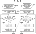
- step S500 When operation of the radiation control apparatus 1006 is started by a user operation or the like (step S500), the control timer 1063 of the radiation control apparatus 1006 starts to measure the time (starts counting) in step S501. Then, in step S502, synchronization time waiting processing is performed.
- the synchronization time is a time at which a predetermined time has elapsed since the control timer 1063 starts counting.
- the control timer 1063 of the radiation control apparatus 1006 measures the elapse time after the start of counting. If the elapse time has not reached the time (synchronization time) at which the predetermined time has elapsed after the start of counting (No in step S502), the radiation control apparatus 1006 waits until the elapse time reaches the synchronization time. If the elapse time reaches the synchronization time (Yes in step S502), the radiation control apparatus 1006 advances the process to step S503.
- step S503 the synchronizer 1064 of the radiation control apparatus 1006 acquires the timer information based on the time measured by the control timer 1063.
- the synchronizer 1064 acquires information of the time measured by the control timer 1063 and, in step S504, outputs the timer information (the information of the time of the control timer 1063) acquired from the control timer 1063 to the radiation imaging apparatus 1001 under the control of the communication controller 1061.
- Transmission processing of the timer information in step S504 is performed every time the synchronization time is reached, regardless of whether the timer information is received in the radiation imaging apparatus 1001.
- step S505 When operation of the radiation imaging apparatus 1001 is started by a user operation or the like (step S505), the sensor timer 228 of the radiation imaging apparatus 1001 starts to measure the time (starts counting) in step S506. Then, in step S507, the controller 225 of the radiation imaging apparatus 1001 monitors whether the communication unit 227 receives the timer information, and waits in a state of waiting for reception of the timer information. If the timer information is not received (No in step S507), the controller 225 of the radiation imaging apparatus 1001 continues the waiting state. If the timer information is received (Yes in step S507), the controller 225 advances the process to step S508.
- step S508 the controller 225 acquires the timer information received by the communication unit 227.
- the controller 225 sets the time of the sensor timer 228 based on the acquired timer information.
- the time of the sensor timer 228 is synchronized with the time of the control timer 1063 of the radiation control apparatus 1006.
- step S509 When the time of the sensor timer 228 is synchronized with the time of the control timer 1063 of the radiation control apparatus 1006 in step S509, the process returns to step S507, and the controller 225 waits in the state of waiting for reception of the timer information. Thereafter, if the timer information is similarly received (Yes in step S507), the controller 225 of the radiation imaging apparatus 1001 sets the time of the sensor timer 228 based on the timer information received by the communication unit 227 (step S509). With this, the time of the control timer 1063 of the radiation control apparatus 1006 and the time of the sensor timer 228 can be accurately synchronized with each other.
- the control timer 1063 of the radiation control apparatus 1006 can start counting the operation time at the same time with power-on of the radiation control apparatus 1006 and can measure the time.
- the synchronizer 1064 acquires the timer information based on the time measured by the control timer 1063.
- the synchronizer 1064 may transmit the timer information to the radiation imaging apparatus 1001, for example, every several ⁇ s, as the synchronization time under the control of the communication controller 1061.
- the timing (synchronization time) at which the synchronizer 1064 transmits the timer information using the communication controller 1061 can be arbitrarily set.
- the controller 225 of the radiation imaging apparatus 1001 transmits the dose information Di(Ti, Xi) to the radiation control apparatus 1006 via the communication unit 227, for example, every synchronization time.
- the generation controller 1062 of the radiation control apparatus 1006 can control output of an irradiation control signal to the radiation source control apparatus 1004 based on the arrival dose information Di(Ti, Xi) transmitted from the radiation imaging apparatus 1001.
- the radiation imaging apparatus 1001 sequentially outputs the dose information Di(Ti, Xi) at a predetermined timing (for example, every synchronization time as described above), and the generation controller 1062 stores the dose information Di'(Ti, Ti', Xi) obtained by adding the acquirement time Ti' in a memory (not shown) in the radiation control apparatus 1006.
- the radiation imaging apparatus 1001 can output the dose information Di to the radiation control apparatus 1006 a plurality of times, and the radiation control apparatus 1006 can store a plurality of pieces of the dose information Di' in the memory.
- Fig. 6A is a table showing examples of pieces of dose information Di'(Ti, Ti', Xi) stored in the memory of the radiation control apparatus 1006.
- the generation controller 1062 of the radiation control apparatus 1006 also stores the threshold dose Y of the arrival dose in the memory.
- the threshold dose Y for stopping radiation irradiation can be arbitrarily set by the user, and can be changed in accordance with the imaging method, imaging portion, imaging condition, and the like.
- the generation controller 1062 of the radiation control apparatus 1006 can specify the threshold time Te which is the predicted time at which the arrival dose entering the radiation imaging apparatus 1001 reaches the preset threshold dose Y. As shown in Fig. 6B , straight-line approximation based on the least square method using a plurality of pieces of the dose information Di or the like can be used to specify the threshold time Te.
- the generation controller 1062 of the radiation control apparatus 1006 can control radiation irradiation via the radiation source 1003 based on a comparison between the threshold dose Y and the dose information Di acquired after the threshold time Te is specified, and the threshold time Te. That is, if the arrival dose obtained from the dose information Di reaches the threshold dose Y or if the time of the control timer 1063 reaches the threshold time Te, the generation controller 1062 of the radiation control apparatus 1006 can control the radiation source 1003 to stop radiation irradiation.
- the communication between the radiation imaging apparatus 1001 and the radiation control apparatus 1006 becomes unstable due to a change in wireless environment or the like, and a shift occurs between the time Ti of the dose information Di output from the radiation imaging apparatus 1001 and the time Ti' at which the radiation control apparatus 1006 acquired the dose information Di. If the difference between the time Ti of the dose information Di output from the radiation imaging apparatus 1001 and the time Ti' at which the radiation control apparatus 1006 acquired the dose information Di exceeds a predetermined threshold value, the generation controller 1062 of the radiation control apparatus 1006 changes the threshold dose Y.
- a threshold change amount ⁇ (Tm' - Tm) is calculated from the delay time (Tm' - Tm) and a slope ⁇ of the approximate straight line used when calculating the threshold dose Y.
- ⁇ Y - ⁇ (Tm' - Tm) ⁇ obtained by subtracting the threshold change amount ⁇ (Tm' - Tm) from the set threshold dose Y is set as a new threshold dose Y'. If the arrival dose obtained from the dose information Di reaches the threshold dose Y' or if the time of the control timer 1063 reaches the threshold time Te, the generation controller 1062 of the radiation control apparatus 1006 changes a signal output to the radiation source control apparatus 1004 so as to switch from the radiation irradiation state to the irradiation stop state.
- a radiation image capturing method performed in the radiation imaging system 1000 includes, for example, processing steps described below.
- the dose Xi of radiation emitted from the radiation source 1003 is detected using the pixel 121 of the radiation imaging apparatus 1001.
- the dose information Di including the dose Xi and the time Ti at which the dose Xi was detected is transmitted to the radiation control apparatus 1006.
- the generation controller 1062 of the radiation control apparatus 1006 acquires, based on the transmitted dose information Di, the threshold time Te at which the arrival dose (integrated dose) entering the radiation imaging apparatus 1001 reaches the threshold dose Y. Based on a comparison between the arrival dose entering the radiation imaging apparatus 1001 and the threshold dose Y or a comparison between the time measured by the control timer 1063 and the threshold time Te, the generation controller 1062 controls the radiation emission from the radiation source 1003.
- the delay time is not limited to a delay caused by the communication between the radiation imaging apparatus 1001 and the radiation control apparatus 1006 as described above.
- a delay occurs before the dose information Di is output, for example, a load is applied on the operation of the radiation imaging apparatus 1001, during a period after the dose information Di is generated in the radiation imaging apparatus 1001 and before the dose information Di is output via the communication unit 227.
- a delay occurs after the dose information Di is received in the radiation control apparatus 1006 and before the dose information Di' is generated in the generation controller 1062.
- the threshold value Y may be changed if the difference (delay time (Tm' - Tm)) between the time Tm of the dose information Dm output from the radiation imaging apparatus 1001 and the time Tm' at which the radiation control apparatus 1006 acquired the dose information Dm exceeds a predetermined threshold.
- Each of the sensor timer 228 and the control timer 1063 used in this embodiment is not limited to a counter that counts the time, and may be configured to measure the actual time.
- the radiation control apparatus 1006 and the control apparatus 1002 are independent apparatuses, but the radiation control apparatus 1006 and the control apparatus 1002 may be integrally formed.
- the radiation control apparatus 1006 changes the threshold dose Y based on the difference between the time Tm included in one piece of dose information Dm among the plurality of pieces of the dose information Di and the time Tm' at which the radiation control apparatus 1006 acquired the one piece of dose information Dm.
- the radiation control apparatus 1006 may change the threshold dose Y based on the differences between the times Ti included in two or more pieces of dose information Di among the plurality of pieces of the dose information Di and the times Ti' at which the radiation control apparatus 1006 acquired the two or more pieces of dose information Di, respectively. That is, the threshold does Y may be corrected using the average time of the delay times of multiple pieces of dose information Di.
- Fig. 7 a case of using the average time of delay times of multiple pieces of dose information Di' will be described.
- Tave T 1 ′ - T 1 + T 2 ′ - T 2 + T 3 ′ - T 3 + . . . + Tm ′ - Tm / m
- the generation controller 1062 calculates a threshold change amount ⁇ Tave from the slope ⁇ of the approximate straight line and the average delay time Tave. Then, (Y - ⁇ Tave) obtained by subtracting the threshold change amount from the set threshold dose Y is stored as the new threshold dose Y' in the memory.
- all pieces of information from the first dose information D1(T1, T1', X1) to the latest dose information Dm(Tm, Tm', Xm) are used to calculate the average delay time Tave, but the information to be used may be arbitrarily selected. That is, an arbitrary number of data before the timing at which the predetermined delay time or more occurs may be used. Also, a predetermined delay time for calculating the average delay time Tave is set, and only the information with which the predetermined delay time or more occurs may be used.
- the threshold dose Y is corrected if the predetermined delay time or more occurs, but the present invention is not limited to this.
- the radiation control apparatus 1006 may change the threshold dose Y every time the dose information Di is acquired. With reference to Figs. 8A to 8C , a case will be described in which the radiation control apparatus 1006 changes the threshold dose Y every time the dose information Di is received.
- the generation controller 1062 of the radiation control apparatus 1006 specifies the threshold dose Y using the dose X1, the time T1, and the time T1' at which the radiation control apparatus 1006 acquired the dose information D1. Further, the generation controller 1062 of the radiation control apparatus 1006 calculates a threshold change amount ⁇ (T1' - T1) from the slope ⁇ of the approximate straight line used upon the specification and a delay time (T1' - T1). Then, ⁇ Y - ⁇ (T1' - T1) ⁇ obtained by subtracting the threshold change amount from the threshold dose Y is stored as a new threshold dose Y1 in the memory.
- a threshold change amount ⁇ (T2' - T2) is calculated from the slope ⁇ of the approximate straight line and a delay time (T2' - T2).
- the method of correcting the threshold dose Y every time the radiation control apparatus 1006 acquires the dose information Di has been described.
- the correction timing may be an arbitrary timing.
- the radiation control apparatus 1006 may change the threshold dose Y based on the dose information Di, among the plurality of pieces of the dose information Di, acquired at a preset timing.
- the radiation control apparatus 1006 may change the threshold dose Y based on the dose information Di, among the plurality of pieces of the dose information Di, acquired at the timing at which a predetermined period has elapsed since the threshold dose Y was last changed.
- the period from when the generation controller 1062 changes the irradiation control signal output to the generation source control apparatus 1004 so as to switch from the radiation irradiation state to the irradiation stop state to when the radiation irradiation from the radiation source 1003 is actually stopped may be taken into consideration.
- the radiation control apparatus 1006, the radiation source control apparatus 1004, and the radiation source 1003 are wired-connected using a cable or the like, and transmit/receive signals. That is, the radiation control apparatus 1006 and the radiation source 1003 are configured to be capable of communication by wired communication.
- a time Tx from when the generation controller 1062 transmits a signal to the radiation source control apparatus 1004 so as to switch from the radiation irradiation state to the irradiation stop state to when the radiation source control apparatus 1004 receives the signal can be a unique value for each radiation imaging system 1000.
- a time Ty from when the radiation source control apparatus 1004 receives the signal to when the radiation source 1003 stops radiation irradiation can be a unique value for each radiation imaging system 1000, each imaging procedure, and each imaging condition.
- a time (Tx + Ty) from when the radiation control apparatus 1006 transmits the signal for causing the radiation source 1003 to stop radiation irradiation based on the dose information Di and the threshold time Te as described above to when the radiation source 1003 stops radiation irradiation can be a unique value according to the radiation imaging system 1000, the imaging procedure, and the imaging condition. Therefore, as shown in Fig. 9 , the radiation control apparatus 1006 may change at least one of the threshold dose Y or the threshold time Te based on the time (Tx + Ty) from when the signal to stop radiation irradiation is transmitted to when the radiation source 1003 stops radiation irradiation.
- the time (Tx + Ty) By taking the time (Tx + Ty) into consideration when correcting the threshold dose Y, it is possible to further suppress excessive radiation irradiation.
- the time (Tx + Ty) may be actually measured at the time of installation of the radiation imaging system 1000, or may be measured in advance before shipping from the factory or the like. Also, the time (Tx + Ty) may be registered in the control apparatus 1002 or the like as a database in advance, and the database may be referred to.
- the generation controller 1062 changes the threshold dose Y.
- a threshold change amount ⁇ (Tm' - Tm - Tx - Ty) is calculated from the delay time (Tm' - Tm) and the unique time (Tx - Ty) according to the radiation imaging system 1000, the imaging procedure, the imaging condition, and the like in addition to the slope ⁇ of the approximation straight line used when specifying the threshold dose Y.
- Embodiment(s) of the present invention can also be realized by a computer of a system or apparatus that reads out and executes computer executable instructions (e.g., one or more programs) recorded on a storage medium (which may also be referred to more fully as a 'non-transitory computer-readable storage medium') to perform the functions of one or more of the above-described embodiment(s) and/or that includes one or more circuits (e.g., application specific integrated circuit (ASIC)) for performing the functions of one or more of the above-described embodiment(s), and by a method performed by the computer of the system or apparatus by, for example, reading out and executing the computer executable instructions from the storage medium to perform the functions of one or more of the above-described embodiment(s) and/or controlling the one or more circuits to perform the functions of one or more of the above-described embodiment(s).
- computer executable instructions e.g., one or more programs
- a storage medium which may also be referred to more fully as
- the computer may comprise one or more processors (e.g., central processing unit (CPU), micro processing unit (MPU)) and may include a network of separate computers or separate processors to read out and execute the computer executable instructions.
- the computer executable instructions may be provided to the computer, for example, from a network or the storage medium.
- the storage medium may include, for example, one or more of a hard disk, a random-access memory (RAM), a read only memory (ROM), a storage of distributed computing systems, an optical disk (such as a compact disc (CD), digital versatile disc (DVD), or Blu-ray Disc (BD) TM ), a flash memory device, a memory card, and the like.
Landscapes
- Health & Medical Sciences (AREA)
- Life Sciences & Earth Sciences (AREA)
- Engineering & Computer Science (AREA)
- Medical Informatics (AREA)
- Physics & Mathematics (AREA)
- High Energy & Nuclear Physics (AREA)
- Molecular Biology (AREA)
- Nuclear Medicine, Radiotherapy & Molecular Imaging (AREA)
- Biomedical Technology (AREA)
- Veterinary Medicine (AREA)
- Public Health (AREA)
- Optics & Photonics (AREA)
- Pathology (AREA)
- Radiology & Medical Imaging (AREA)
- Biophysics (AREA)
- Heart & Thoracic Surgery (AREA)
- Surgery (AREA)
- Animal Behavior & Ethology (AREA)
- General Health & Medical Sciences (AREA)
- General Physics & Mathematics (AREA)
- Spectroscopy & Molecular Physics (AREA)
- Apparatus For Radiation Diagnosis (AREA)
- Measurement Of Radiation (AREA)
Claims (14)
- Strahlungsbildgebungssystem (1000), das eine Strahlungsbildgebungsvorrichtung (1001) umfasst, die konfiguriert ist, Strahlung zu detektieren, die von einer Strahlungsquelle (1003) emittiert wird, und eine Strahlungssteuervorrichtung (1006), die konfiguriert ist, die Strahlungsquelle (1003) zu steuern, dadurch gekennzeichnet, dassdie Strahlungsbildgebungsvorrichtung (1001) konfiguriert ist, ein Dosisinformationselement (Di(Ti,Xi)), das eine Dosis (Xi) von Strahlung, die in die Strahlungsbildgebungsvorrichtung (1001) eintritt, und eine Zeit (Ti), zu der die Dosis detektiert wurde, enthält, während einer Strahlungsbestrahlung mehrere Male an die Strahlungssteuervorrichtung (1006) auszugeben, unddie Strahlungssteuervorrichtung (1006) konfiguriert ist,eine Schwellenwertdosis (Y) zu ändern, basierend auf einer Differenz zwischen der Zeit (Ti), die in mindestens einem der Dosisinformationselemente von der Strahlungsbildgebungsvorrichtung (1001) enthalten ist, und einer Zeit (Ti'), zu der die Strahlungssteuervorrichtung (1006) das mindestens eine Dosisinformationselement empfangen hat, unddie Strahlungsquelle (1003) zu steuern, um die Strahlungsbestrahlung basierend auf dem mindestens einen der Dosisinformationselemente und der Schwellenwertdosis zu stoppen.
- System nach Anspruch 1, wobei
die Strahlungssteuervorrichtung basierend auf den Dosisinformationselementen eine Schwellenwertzeit spezifiziert, zu der eine Ankunftsdosis, die in die Strahlungsbildgebungsvorrichtung eintritt, die Schwellenwertdosis erreicht. - System nach Anspruch 2, wobei
wenn die Ankunftsdosis die Schwellenwertdosis erreicht oder wenn eine Zeit die Schwellenwertzeit erreicht, die Strahlungssteuervorrichtung die Strahlungsquelle steuert, um die Strahlungsbestrahlung zu stoppen. - System nach Anspruch 2 oder 3, wobei
basierend auf den Dosisinformationselementen und der Schwellenwertzeit die Strahlungssteuervorrichtung ein Signal überträgt, das die Strahlungsquelle veranlasst, die Strahlungsbestrahlung zu stoppen. - System nach Anspruch 4, wobei
basierend auf einer Zeit ab dem Zeitpunkt, zu dem das Signal übertragen wird, bis zu dem Zeitpunkt, zu dem die Strahlungsquelle die Strahlungsbestrahlung stoppt, die Strahlungssteuervorrichtung zumindest die Schwellenwertdosis oder die Schwellenwertzeit einstellt. - System nach Anspruch 5, wobei
die Strahlungssteuervorrichtung und die Strahlungsquelle konfiguriert sind, durch drahtgebundene Kommunikation kommunikationsfähig zu sein, und die Strahlungsbildgebungsvorrichtung und die Strahlungssteuervorrichtung konfiguriert sind, durch Drahtloskommunikation kommunikationsfähig zu sein. - System nach einem der Ansprüche 1 bis 6, wobei
die Strahlungssteuervorrichtung konfiguriert ist, die Schwellenwertdosis basierend auf Differenzen zwischen den Zeiten, die in zwei oder mehr Dosisinformationselementen unter den mehreren Dosisinformationselementen enthalten sind, und Zeiten, zu denen die Strahlungssteuervorrichtung die zwei oder mehr Dosisinformationselemente erfasst hat, jeweils zu ändern. - System nach einem der Ansprüche 1 bis 7, wobei
wenn die Differenz einen vorbestimmten Schwellenwert überschreitet, die Strahlungssteuervorrichtung die Schwellenwertdosis ändert. - System nach einem der Ansprüche 1 bis 8, wobei
die Strahlungssteuervorrichtung die Schwellenwertdosis basierend auf mindestens einem der Dosisinformationselemente unter den mehreren Dosisinformationselementen, die zu einem voreingestellten Zeitpunkt erfasst werden, ändert. - System nach einem der Ansprüche 1 bis 9, wobei
die Strahlungssteuervorrichtung die Schwellenwertdosis basierend auf mindestens einem Dosisinformationselement unter den mehreren Dosisinformationselementen, die zu einem Zeitpunkt erfasst werden, zu dem ein vorbestimmter Zeitraum verstrichen ist, seit die Schwellenwertdosis zuletzt geändert wurde, ändert. - System nach einem der Ansprüche 1 bis 10, dadurch gekennzeichnet, dass es ferner
einen Synchronisator umfasst, der konfiguriert ist, eine Zeit der Strahlungsbildgebungsvorrichtung und eine Zeit der Strahlungssteuervorrichtung zu synchronisieren. - Strahlungssteuervorrichtung (1006) zum Steuern einer Strahlungsquelle (1003), die konfiguriert ist, Strahlung an eine Strahlungsbildgebungsvorrichtung (1001) zu emittieren, dadurch gekennzeichnet, dassdie Strahlungssteuervorrichtung (1006) konfiguriert ist,von der Strahlungsbildgebungsvorrichtung (1001) während einer Strahlungsbestrahlung mehrere Male ein Dosisinformationselement (Di(Ti,Xi)) zu empfangen, das eine Dosis (Xi) von Strahlung, die in die Strahlungsbildgebungsvorrichtung (1001) eintritt, und eine Zeit (Ti), zu der die Dosis detektiert wurde, enthält,eine Schwellenwertdosis (Y) basierend auf einer Differenz zwischen der Zeit (Ti), die in mindestens einem der Dosisinformationselemente von der Strahlungsbildgebungsvorrichtung (1001) enthalten ist, und einer Zeit (Ti'), zu der die Strahlungssteuervorrichtung (1006) das mindestens eine Dosisinformationselement empfangen hat, zu ändern, unddie Strahlungsquelle (1003) zu steuern, um die Strahlungsbestrahlung basierend auf dem mindestens einen Dosisinformationselement und der Schwellenwertdosis zu stoppen.
- Steuerverfahren einer Strahlungssteuervorrichtung (1006), das eine Strahlungsquelle (1003) steuert, die konfiguriert ist, Strahlung an eine Strahlungsbildgebungsvorrichtung (1001) zu emittieren, wobei das Verfahren umfasst:Empfangen von der Strahlungsbildgebungsvorrichtung (1001), mehrere Male während einer Strahlungsbestrahlung, eines Dosisinformationselements (Di(Ti,Xi)), das eine Dosis (Xi) von Strahlung, die in die Strahlungsbildgebungsvorrichtung (1001) eintritt, und eine Zeit (Ti), zu der die Dosis detektiert wurde, enthält,Ändern einer Schwellenwertdosis (Y) basierend auf einer Differenz zwischen der Zeit (Ti), die in mindestens einem der Dosisinformationselemente von der Strahlungsbildgebungsvorrichtung (1001) enthalten ist, und einer Zeit (Ti'), zu der die Strahlungssteuervorrichtung (1006) das mindestens eine Dosisinformationselement empfangen hat; undSteuern der Strahlungsquelle (1003), um die Strahlungsbestrahlung basierend auf dem mindestens einen der Dosisinformationselemente und der Schwellenwertdosis zu stoppen.
- Programm, das einen Computer veranlasst, das Steuerverfahren nach Anspruch 13 auszuführen.
Applications Claiming Priority (1)
| Application Number | Priority Date | Filing Date | Title |
|---|---|---|---|
| JP2021172654A JP7441203B2 (ja) | 2021-10-21 | 2021-10-21 | 放射線撮像システム、放射線制御装置、放射線撮像システムの制御方法、放射線制御装置の制御方法、プログラム、および、記憶媒体 |
Publications (2)
| Publication Number | Publication Date |
|---|---|
| EP4169448A1 EP4169448A1 (de) | 2023-04-26 |
| EP4169448B1 true EP4169448B1 (de) | 2025-06-11 |
Family
ID=83898322
Family Applications (1)
| Application Number | Title | Priority Date | Filing Date |
|---|---|---|---|
| EP22201923.4A Active EP4169448B1 (de) | 2021-10-21 | 2022-10-17 | Strahlungsabbildungssystem, strahlungssteuerungsvorrichtung, steuerungsverfahren für strahlungssteuerungsvorrichtung und programm |
Country Status (3)
| Country | Link |
|---|---|
| US (1) | US12242004B2 (de) |
| EP (1) | EP4169448B1 (de) |
| JP (1) | JP7441203B2 (de) |
Families Citing this family (4)
| Publication number | Priority date | Publication date | Assignee | Title |
|---|---|---|---|---|
| JP7441203B2 (ja) * | 2021-10-21 | 2024-02-29 | キヤノン株式会社 | 放射線撮像システム、放射線制御装置、放射線撮像システムの制御方法、放射線制御装置の制御方法、プログラム、および、記憶媒体 |
| JP2023159686A (ja) * | 2022-04-20 | 2023-11-01 | キヤノン株式会社 | 放射線撮像装置、放射線撮像システム、および放射線撮像装置の制御方法 |
| JP7551697B2 (ja) * | 2022-06-28 | 2024-09-17 | キヤノン株式会社 | 放射線撮影システム、放射線撮像装置、および放射線撮影システムの制御方法 |
| US20240138799A1 (en) * | 2022-11-02 | 2024-05-02 | Canon Kabushiki Kaisha | Radiographic imaging apparatus, radiographic imaging system, and method for controlling radiographic imaging apparatus |
Family Cites Families (10)
| Publication number | Priority date | Publication date | Assignee | Title |
|---|---|---|---|---|
| US7429737B2 (en) | 2006-11-09 | 2008-09-30 | Carestream Health, Inc. | Retrofit digital mammography detector |
| JP5914404B2 (ja) | 2012-04-12 | 2016-05-11 | 富士フイルム株式会社 | X線露出制御装置、x線画像検出装置及びx線画像撮影システム |
| JP5975733B2 (ja) | 2012-05-25 | 2016-08-23 | 富士フイルム株式会社 | 放射線画像検出装置およびその駆動制御方法、並びに放射線撮影システム |
| JP6752049B2 (ja) | 2016-05-09 | 2020-09-09 | キヤノン株式会社 | 放射線撮像システム、放射線撮像システムの制御方法およびプログラム |
| JP2017221328A (ja) | 2016-06-14 | 2017-12-21 | キヤノン株式会社 | 放射線撮影装置及び放射線撮影装置の制御方法 |
| JP2019076219A (ja) | 2017-10-20 | 2019-05-23 | キヤノン株式会社 | 放射線撮影システム、時刻同期方法、及びプログラム |
| WO2021177229A1 (ja) * | 2020-03-04 | 2021-09-10 | キヤノン株式会社 | 放射線撮影システム、制御装置、及び放射線撮影システムの制御方法 |
| JP2021137255A (ja) | 2020-03-04 | 2021-09-16 | キヤノン株式会社 | 放射線撮影システム及びその制御方法 |
| CN112738391B (zh) | 2020-12-23 | 2023-04-18 | 上海奕瑞光电子科技股份有限公司 | 自动曝光控制方法及系统 |
| JP7441203B2 (ja) * | 2021-10-21 | 2024-02-29 | キヤノン株式会社 | 放射線撮像システム、放射線制御装置、放射線撮像システムの制御方法、放射線制御装置の制御方法、プログラム、および、記憶媒体 |
-
2021
- 2021-10-21 JP JP2021172654A patent/JP7441203B2/ja active Active
-
2022
- 2022-10-17 EP EP22201923.4A patent/EP4169448B1/de active Active
- 2022-10-19 US US18/047,987 patent/US12242004B2/en active Active
Also Published As
| Publication number | Publication date |
|---|---|
| US20230126864A1 (en) | 2023-04-27 |
| US12242004B2 (en) | 2025-03-04 |
| EP4169448A1 (de) | 2023-04-26 |
| JP7441203B2 (ja) | 2024-02-29 |
| JP2023062593A (ja) | 2023-05-08 |
Similar Documents
| Publication | Publication Date | Title |
|---|---|---|
| EP4169448B1 (de) | Strahlungsabbildungssystem, strahlungssteuerungsvorrichtung, steuerungsverfahren für strahlungssteuerungsvorrichtung und programm | |
| US10993683B2 (en) | Radiation imaging apparatus and radiation imaging system | |
| JP6752049B2 (ja) | 放射線撮像システム、放射線撮像システムの制御方法およびプログラム | |
| US10506696B2 (en) | Radiation imaging apparatus, radiation imaging system, radiation imaging method, and storage medium | |
| US12121390B2 (en) | Control system and radiographic imaging system | |
| US10992883B2 (en) | Radiation imaging system | |
| US10539684B2 (en) | Radiation imaging apparatus, radiation imaging system, control method of radiation imaging apparatus, and non-transitory computer-readable storage medium | |
| US10849577B2 (en) | Radiation imaging apparatus and radiation imaging system | |
| JP2017094010A (ja) | 放射線撮像装置、制御装置、放射線撮像システム、および放射線撮像システムの制御方法 | |
| US10856833B2 (en) | Radiation imaging apparatus comprising a processing unit configured to set a control timing of a radiation source with respect to a wired or wireless communication with an imaging capturing unit | |
| US20120161026A1 (en) | Image capture controller and radiographic image capture system | |
| US12167925B2 (en) | Control terminal, storage medium and radiographic imaging system | |
| US10754046B2 (en) | Radiation imaging system and radiation imaging apparatus | |
| WO2017085905A1 (en) | Radiation imaging system, signal processing apparatus, and signal processing method for radiographic image | |
| US11709283B2 (en) | Radiography system | |
| US12324698B2 (en) | Radiation imaging system, radiation imaging apparatus, control method of radiation imaging system, and non-transitory computer-readable storage medium | |
| JP6858061B2 (ja) | 放射線撮影システム、放射線撮影装置、放射線撮影方法およびプログラム | |
| EP4420611B1 (de) | Strahlungsabbildungssystem | |
| US12527537B2 (en) | Radiation imaging system, control apparatus, radiation imaging apparatus, control methods therefor, and non-transitory computer-readable storage medium | |
| JP2017118988A (ja) | 放射線撮像システム、通信制御方法及びプログラム |
Legal Events
| Date | Code | Title | Description |
|---|---|---|---|
| PUAI | Public reference made under article 153(3) epc to a published international application that has entered the european phase |
Free format text: ORIGINAL CODE: 0009012 |
|
| STAA | Information on the status of an ep patent application or granted ep patent |
Free format text: STATUS: THE APPLICATION HAS BEEN PUBLISHED |
|
| AK | Designated contracting states |
Kind code of ref document: A1 Designated state(s): AL AT BE BG CH CY CZ DE DK EE ES FI FR GB GR HR HU IE IS IT LI LT LU LV MC ME MK MT NL NO PL PT RO RS SE SI SK SM TR |
|
| STAA | Information on the status of an ep patent application or granted ep patent |
Free format text: STATUS: REQUEST FOR EXAMINATION WAS MADE |
|
| 17P | Request for examination filed |
Effective date: 20231026 |
|
| RBV | Designated contracting states (corrected) |
Designated state(s): AL AT BE BG CH CY CZ DE DK EE ES FI FR GB GR HR HU IE IS IT LI LT LU LV MC ME MK MT NL NO PL PT RO RS SE SI SK SM TR |
|
| GRAP | Despatch of communication of intention to grant a patent |
Free format text: ORIGINAL CODE: EPIDOSNIGR1 |
|
| STAA | Information on the status of an ep patent application or granted ep patent |
Free format text: STATUS: GRANT OF PATENT IS INTENDED |
|
| INTG | Intention to grant announced |
Effective date: 20250115 |
|
| GRAS | Grant fee paid |
Free format text: ORIGINAL CODE: EPIDOSNIGR3 |
|
| GRAA | (expected) grant |
Free format text: ORIGINAL CODE: 0009210 |
|
| STAA | Information on the status of an ep patent application or granted ep patent |
Free format text: STATUS: THE PATENT HAS BEEN GRANTED |
|
| AK | Designated contracting states |
Kind code of ref document: B1 Designated state(s): AL AT BE BG CH CY CZ DE DK EE ES FI FR GB GR HR HU IE IS IT LI LT LU LV MC ME MK MT NL NO PL PT RO RS SE SI SK SM TR |
|
| REG | Reference to a national code |
Ref country code: GB Ref legal event code: FG4D |
|
| REG | Reference to a national code |
Ref country code: CH Ref legal event code: EP |
|
| REG | Reference to a national code |
Ref country code: DE Ref legal event code: R096 Ref document number: 602022015756 Country of ref document: DE |
|
| REG | Reference to a national code |
Ref country code: IE Ref legal event code: FG4D |
|
| PG25 | Lapsed in a contracting state [announced via postgrant information from national office to epo] |
Ref country code: ES Free format text: LAPSE BECAUSE OF FAILURE TO SUBMIT A TRANSLATION OF THE DESCRIPTION OR TO PAY THE FEE WITHIN THE PRESCRIBED TIME-LIMIT Effective date: 20250611 Ref country code: FI Free format text: LAPSE BECAUSE OF FAILURE TO SUBMIT A TRANSLATION OF THE DESCRIPTION OR TO PAY THE FEE WITHIN THE PRESCRIBED TIME-LIMIT Effective date: 20250611 |
|
| REG | Reference to a national code |
Ref country code: LT Ref legal event code: MG9D |
|
| PG25 | Lapsed in a contracting state [announced via postgrant information from national office to epo] |
Ref country code: GR Free format text: LAPSE BECAUSE OF FAILURE TO SUBMIT A TRANSLATION OF THE DESCRIPTION OR TO PAY THE FEE WITHIN THE PRESCRIBED TIME-LIMIT Effective date: 20250912 Ref country code: NO Free format text: LAPSE BECAUSE OF FAILURE TO SUBMIT A TRANSLATION OF THE DESCRIPTION OR TO PAY THE FEE WITHIN THE PRESCRIBED TIME-LIMIT Effective date: 20250911 |
|
| REG | Reference to a national code |
Ref country code: NL Ref legal event code: MP Effective date: 20250611 |
|
| PG25 | Lapsed in a contracting state [announced via postgrant information from national office to epo] |
Ref country code: BG Free format text: LAPSE BECAUSE OF FAILURE TO SUBMIT A TRANSLATION OF THE DESCRIPTION OR TO PAY THE FEE WITHIN THE PRESCRIBED TIME-LIMIT Effective date: 20250611 |
|
| PG25 | Lapsed in a contracting state [announced via postgrant information from national office to epo] |
Ref country code: HR Free format text: LAPSE BECAUSE OF FAILURE TO SUBMIT A TRANSLATION OF THE DESCRIPTION OR TO PAY THE FEE WITHIN THE PRESCRIBED TIME-LIMIT Effective date: 20250611 |
|
| PG25 | Lapsed in a contracting state [announced via postgrant information from national office to epo] |
Ref country code: RS Free format text: LAPSE BECAUSE OF FAILURE TO SUBMIT A TRANSLATION OF THE DESCRIPTION OR TO PAY THE FEE WITHIN THE PRESCRIBED TIME-LIMIT Effective date: 20250911 |
|
| PG25 | Lapsed in a contracting state [announced via postgrant information from national office to epo] |
Ref country code: LV Free format text: LAPSE BECAUSE OF FAILURE TO SUBMIT A TRANSLATION OF THE DESCRIPTION OR TO PAY THE FEE WITHIN THE PRESCRIBED TIME-LIMIT Effective date: 20250611 |
|
| PG25 | Lapsed in a contracting state [announced via postgrant information from national office to epo] |
Ref country code: NL Free format text: LAPSE BECAUSE OF FAILURE TO SUBMIT A TRANSLATION OF THE DESCRIPTION OR TO PAY THE FEE WITHIN THE PRESCRIBED TIME-LIMIT Effective date: 20250611 |
|
| PG25 | Lapsed in a contracting state [announced via postgrant information from national office to epo] |
Ref country code: PT Free format text: LAPSE BECAUSE OF FAILURE TO SUBMIT A TRANSLATION OF THE DESCRIPTION OR TO PAY THE FEE WITHIN THE PRESCRIBED TIME-LIMIT Effective date: 20251013 |
|
| REG | Reference to a national code |
Ref country code: AT Ref legal event code: MK05 Ref document number: 1801735 Country of ref document: AT Kind code of ref document: T Effective date: 20250611 |
|
| PG25 | Lapsed in a contracting state [announced via postgrant information from national office to epo] |
Ref country code: IS Free format text: LAPSE BECAUSE OF FAILURE TO SUBMIT A TRANSLATION OF THE DESCRIPTION OR TO PAY THE FEE WITHIN THE PRESCRIBED TIME-LIMIT Effective date: 20251011 |
|
| PGFP | Annual fee paid to national office [announced via postgrant information from national office to epo] |
Ref country code: DE Payment date: 20250923 Year of fee payment: 4 |
|
| PG25 | Lapsed in a contracting state [announced via postgrant information from national office to epo] |
Ref country code: AT Free format text: LAPSE BECAUSE OF FAILURE TO SUBMIT A TRANSLATION OF THE DESCRIPTION OR TO PAY THE FEE WITHIN THE PRESCRIBED TIME-LIMIT Effective date: 20250611 Ref country code: SM Free format text: LAPSE BECAUSE OF FAILURE TO SUBMIT A TRANSLATION OF THE DESCRIPTION OR TO PAY THE FEE WITHIN THE PRESCRIBED TIME-LIMIT Effective date: 20250611 |
|
| PG25 | Lapsed in a contracting state [announced via postgrant information from national office to epo] |
Ref country code: CZ Free format text: LAPSE BECAUSE OF FAILURE TO SUBMIT A TRANSLATION OF THE DESCRIPTION OR TO PAY THE FEE WITHIN THE PRESCRIBED TIME-LIMIT Effective date: 20250611 |
|
| PG25 | Lapsed in a contracting state [announced via postgrant information from national office to epo] |
Ref country code: PL Free format text: LAPSE BECAUSE OF FAILURE TO SUBMIT A TRANSLATION OF THE DESCRIPTION OR TO PAY THE FEE WITHIN THE PRESCRIBED TIME-LIMIT Effective date: 20250611 |
|
| PG25 | Lapsed in a contracting state [announced via postgrant information from national office to epo] |
Ref country code: EE Free format text: LAPSE BECAUSE OF FAILURE TO SUBMIT A TRANSLATION OF THE DESCRIPTION OR TO PAY THE FEE WITHIN THE PRESCRIBED TIME-LIMIT Effective date: 20250611 |
|
| PG25 | Lapsed in a contracting state [announced via postgrant information from national office to epo] |
Ref country code: SK Free format text: LAPSE BECAUSE OF FAILURE TO SUBMIT A TRANSLATION OF THE DESCRIPTION OR TO PAY THE FEE WITHIN THE PRESCRIBED TIME-LIMIT Effective date: 20250611 |
|
| PG25 | Lapsed in a contracting state [announced via postgrant information from national office to epo] |
Ref country code: RO Free format text: LAPSE BECAUSE OF FAILURE TO SUBMIT A TRANSLATION OF THE DESCRIPTION OR TO PAY THE FEE WITHIN THE PRESCRIBED TIME-LIMIT Effective date: 20250611 |