EP4168658B1 - Flugzeugturbomaschine mit wiedergewonnenem zyklus - Google Patents
Flugzeugturbomaschine mit wiedergewonnenem zyklus Download PDFInfo
- Publication number
- EP4168658B1 EP4168658B1 EP21737729.0A EP21737729A EP4168658B1 EP 4168658 B1 EP4168658 B1 EP 4168658B1 EP 21737729 A EP21737729 A EP 21737729A EP 4168658 B1 EP4168658 B1 EP 4168658B1
- Authority
- EP
- European Patent Office
- Prior art keywords
- turbomachine
- port
- conduit
- volutes
- volute
- Prior art date
- Legal status (The legal status is an assumption and is not a legal conclusion. Google has not performed a legal analysis and makes no representation as to the accuracy of the status listed.)
- Active
Links
Images
Classifications
-
- F—MECHANICAL ENGINEERING; LIGHTING; HEATING; WEAPONS; BLASTING
- F02—COMBUSTION ENGINES; HOT-GAS OR COMBUSTION-PRODUCT ENGINE PLANTS
- F02C—GAS-TURBINE PLANTS; AIR INTAKES FOR JET-PROPULSION PLANTS; CONTROLLING FUEL SUPPLY IN AIR-BREATHING JET-PROPULSION PLANTS
- F02C3/00—Gas-turbine plants characterised by the use of combustion products as the working fluid
- F02C3/04—Gas-turbine plants characterised by the use of combustion products as the working fluid having a turbine driving a compressor
- F02C3/10—Gas-turbine plants characterised by the use of combustion products as the working fluid having a turbine driving a compressor with another turbine driving an output shaft but not driving the compressor
- F02C3/103—Gas-turbine plants characterised by the use of combustion products as the working fluid having a turbine driving a compressor with another turbine driving an output shaft but not driving the compressor the compressor being of the centrifugal type
-
- F—MECHANICAL ENGINEERING; LIGHTING; HEATING; WEAPONS; BLASTING
- F02—COMBUSTION ENGINES; HOT-GAS OR COMBUSTION-PRODUCT ENGINE PLANTS
- F02C—GAS-TURBINE PLANTS; AIR INTAKES FOR JET-PROPULSION PLANTS; CONTROLLING FUEL SUPPLY IN AIR-BREATHING JET-PROPULSION PLANTS
- F02C3/00—Gas-turbine plants characterised by the use of combustion products as the working fluid
- F02C3/04—Gas-turbine plants characterised by the use of combustion products as the working fluid having a turbine driving a compressor
- F02C3/10—Gas-turbine plants characterised by the use of combustion products as the working fluid having a turbine driving a compressor with another turbine driving an output shaft but not driving the compressor
-
- F—MECHANICAL ENGINEERING; LIGHTING; HEATING; WEAPONS; BLASTING
- F01—MACHINES OR ENGINES IN GENERAL; ENGINE PLANTS IN GENERAL; STEAM ENGINES
- F01D—NON-POSITIVE DISPLACEMENT MACHINES OR ENGINES, e.g. STEAM TURBINES
- F01D9/00—Stators
- F01D9/02—Nozzles; Nozzle boxes; Stator blades; Guide conduits, e.g. individual nozzles
- F01D9/026—Scrolls for radial machines or engines
-
- F—MECHANICAL ENGINEERING; LIGHTING; HEATING; WEAPONS; BLASTING
- F02—COMBUSTION ENGINES; HOT-GAS OR COMBUSTION-PRODUCT ENGINE PLANTS
- F02C—GAS-TURBINE PLANTS; AIR INTAKES FOR JET-PROPULSION PLANTS; CONTROLLING FUEL SUPPLY IN AIR-BREATHING JET-PROPULSION PLANTS
- F02C3/00—Gas-turbine plants characterised by the use of combustion products as the working fluid
- F02C3/04—Gas-turbine plants characterised by the use of combustion products as the working fluid having a turbine driving a compressor
- F02C3/08—Gas-turbine plants characterised by the use of combustion products as the working fluid having a turbine driving a compressor the compressor comprising at least one radial stage
-
- F—MECHANICAL ENGINEERING; LIGHTING; HEATING; WEAPONS; BLASTING
- F02—COMBUSTION ENGINES; HOT-GAS OR COMBUSTION-PRODUCT ENGINE PLANTS
- F02C—GAS-TURBINE PLANTS; AIR INTAKES FOR JET-PROPULSION PLANTS; CONTROLLING FUEL SUPPLY IN AIR-BREATHING JET-PROPULSION PLANTS
- F02C7/00—Features, components parts, details or accessories, not provided for in, or of interest apart form groups F02C1/00 - F02C6/00; Air intakes for jet-propulsion plants
- F02C7/08—Heating air supply before combustion, e.g. by exhaust gases
-
- F—MECHANICAL ENGINEERING; LIGHTING; HEATING; WEAPONS; BLASTING
- F04—POSITIVE - DISPLACEMENT MACHINES FOR LIQUIDS; PUMPS FOR LIQUIDS OR ELASTIC FLUIDS
- F04D—NON-POSITIVE-DISPLACEMENT PUMPS
- F04D17/00—Radial-flow pumps, e.g. centrifugal pumps; Helico-centrifugal pumps
- F04D17/08—Centrifugal pumps
- F04D17/10—Centrifugal pumps for compressing or evacuating
- F04D17/12—Multi-stage pumps
- F04D17/122—Multi-stage pumps the individual rotor discs being, one for each stage, on a common shaft and axially spaced, e.g. conventional centrifugal multi- stage compressors
-
- F—MECHANICAL ENGINEERING; LIGHTING; HEATING; WEAPONS; BLASTING
- F04—POSITIVE - DISPLACEMENT MACHINES FOR LIQUIDS; PUMPS FOR LIQUIDS OR ELASTIC FLUIDS
- F04D—NON-POSITIVE-DISPLACEMENT PUMPS
- F04D25/00—Pumping installations or systems
- F04D25/02—Units comprising pumps and their driving means
- F04D25/04—Units comprising pumps and their driving means the pump being fluid-driven
-
- F—MECHANICAL ENGINEERING; LIGHTING; HEATING; WEAPONS; BLASTING
- F04—POSITIVE - DISPLACEMENT MACHINES FOR LIQUIDS; PUMPS FOR LIQUIDS OR ELASTIC FLUIDS
- F04D—NON-POSITIVE-DISPLACEMENT PUMPS
- F04D29/00—Details, component parts, or accessories
- F04D29/40—Casings; Connections of working fluid
- F04D29/42—Casings; Connections of working fluid for radial or helico-centrifugal pumps
- F04D29/44—Fluid-guiding means, e.g. diffusers
- F04D29/441—Fluid-guiding means, e.g. diffusers especially adapted for elastic fluid pumps
-
- F—MECHANICAL ENGINEERING; LIGHTING; HEATING; WEAPONS; BLASTING
- F04—POSITIVE - DISPLACEMENT MACHINES FOR LIQUIDS; PUMPS FOR LIQUIDS OR ELASTIC FLUIDS
- F04D—NON-POSITIVE-DISPLACEMENT PUMPS
- F04D29/00—Details, component parts, or accessories
- F04D29/58—Cooling; Heating; Diminishing heat transfer
- F04D29/582—Cooling; Heating; Diminishing heat transfer specially adapted for elastic fluid pumps
- F04D29/5826—Cooling at least part of the working fluid in a heat exchanger
-
- B—PERFORMING OPERATIONS; TRANSPORTING
- B64—AIRCRAFT; AVIATION; COSMONAUTICS
- B64C—AEROPLANES; HELICOPTERS
- B64C27/00—Rotorcraft; Rotors peculiar thereto
- B64C27/04—Helicopters
- B64C27/12—Rotor drives
-
- F—MECHANICAL ENGINEERING; LIGHTING; HEATING; WEAPONS; BLASTING
- F04—POSITIVE - DISPLACEMENT MACHINES FOR LIQUIDS; PUMPS FOR LIQUIDS OR ELASTIC FLUIDS
- F04D—NON-POSITIVE-DISPLACEMENT PUMPS
- F04D29/00—Details, component parts, or accessories
- F04D29/40—Casings; Connections of working fluid
- F04D29/42—Casings; Connections of working fluid for radial or helico-centrifugal pumps
- F04D29/4206—Casings; Connections of working fluid for radial or helico-centrifugal pumps especially adapted for elastic fluid pumps
- F04D29/4226—Fan casings
- F04D29/4233—Fan casings with volutes extending mainly in axial or radially inward direction
-
- F—MECHANICAL ENGINEERING; LIGHTING; HEATING; WEAPONS; BLASTING
- F05—INDEXING SCHEMES RELATING TO ENGINES OR PUMPS IN VARIOUS SUBCLASSES OF CLASSES F01-F04
- F05D—INDEXING SCHEME FOR ASPECTS RELATING TO NON-POSITIVE-DISPLACEMENT MACHINES OR ENGINES, GAS-TURBINES OR JET-PROPULSION PLANTS
- F05D2220/00—Application
- F05D2220/30—Application in turbines
- F05D2220/32—Application in turbines in gas turbines
- F05D2220/329—Application in turbines in gas turbines in helicopters
-
- F—MECHANICAL ENGINEERING; LIGHTING; HEATING; WEAPONS; BLASTING
- F05—INDEXING SCHEMES RELATING TO ENGINES OR PUMPS IN VARIOUS SUBCLASSES OF CLASSES F01-F04
- F05D—INDEXING SCHEME FOR ASPECTS RELATING TO NON-POSITIVE-DISPLACEMENT MACHINES OR ENGINES, GAS-TURBINES OR JET-PROPULSION PLANTS
- F05D2250/00—Geometry
- F05D2250/50—Inlet or outlet
-
- F—MECHANICAL ENGINEERING; LIGHTING; HEATING; WEAPONS; BLASTING
- F05—INDEXING SCHEMES RELATING TO ENGINES OR PUMPS IN VARIOUS SUBCLASSES OF CLASSES F01-F04
- F05D—INDEXING SCHEME FOR ASPECTS RELATING TO NON-POSITIVE-DISPLACEMENT MACHINES OR ENGINES, GAS-TURBINES OR JET-PROPULSION PLANTS
- F05D2260/00—Function
- F05D2260/20—Heat transfer, e.g. cooling
- F05D2260/213—Heat transfer, e.g. cooling by the provision of a heat exchanger within the cooling circuit
-
- Y—GENERAL TAGGING OF NEW TECHNOLOGICAL DEVELOPMENTS; GENERAL TAGGING OF CROSS-SECTIONAL TECHNOLOGIES SPANNING OVER SEVERAL SECTIONS OF THE IPC; TECHNICAL SUBJECTS COVERED BY FORMER USPC CROSS-REFERENCE ART COLLECTIONS [XRACs] AND DIGESTS
- Y02—TECHNOLOGIES OR APPLICATIONS FOR MITIGATION OR ADAPTATION AGAINST CLIMATE CHANGE
- Y02T—CLIMATE CHANGE MITIGATION TECHNOLOGIES RELATED TO TRANSPORTATION
- Y02T50/00—Aeronautics or air transport
- Y02T50/60—Efficient propulsion technologies, e.g. for aircraft
Definitions
- the present invention relates to an aircraft turbomachine equipped with a set of scrolls for implementing a recovered cycle.
- An aircraft turbomachine comprises a gas generator comprising from upstream to downstream, in the direction of gas flow, at least one compressor, an annular combustion chamber, and at least one turbine.
- the compressor is supplied with air and compresses it.
- the compressed air is mixed with fuel and burned in the combustion chamber which supplies combustion gases to the turbine.
- These combustion gases expand in the turbine and rotate its rotor, which in turn drives, via a common shaft, the rotor of the compressor.
- a turbomachine may be equipped with one or more bodies each comprising a compressor rotor connected by a shaft to a turbine rotor.
- turbomachines where a free turbine is mounted downstream of the turbomachine body(ies).
- a turbine is free to the extent that its rotor is not connected by a shaft to a compressor rotor.
- a turbomachine can comprise several successive compressors (for example a low pressure compressor followed by a high pressure compressor), as well as several successive turbines (for example a high pressure turbine followed by a free turbine or a low pressure turbine).
- a conventional cycle turbomachine is understood to mean a turbomachine in which the compressed air leaving the compressor(s) directly feeds the combustion chamber.
- a recuperative cycle turbomachine is understood to mean a turbomachine in which the combustion gases flowing out of the turbine(s) are used to heat the compressed air leaving the compressor(s) and intended to supply the combustion chamber. This This technology improves the performance of the turbomachine because the amount of fuel required to reach the operating temperature of the turbomachine is less than that required in a conventional cycle turbomachine.
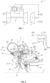
- FIG. 1 represents in a very schematic way a turbomachine with recuperated cycle.
- the turbomachine 1 comprises from upstream to downstream a compressor 2, an annular combustion chamber 3, a turbine 4 and a free turbine 5.
- the rotors of the compressor 3 and the turbine 4 are connected together by a shaft 6 and form a single body.
- the turbomachine 1 comprises a heat exchanger 7, a first circuit of which is supplied by combustion gases taken from the outlet of the free turbine 5.
- the exchanger 7 comprises a second circuit which is supplied with compressed air leaving the compressor 2 and which provides heated compressed air to the combustion chamber 3.
- a centrifugal compressor is a compressor that has an inlet oriented parallel to the longitudinal axis of the turbomachine, and an outlet that is oriented radially relative to this axis.
- This type of compressor is associated with a system for diffusing and straightening the compressed air flow.
- This system comprises a diffuser-straightener assembly and therefore comprises an annular diffuser that is oriented substantially radially and that is aligned with the outlet of the centrifugal compressor, and an annular straightener that is oriented substantially axially to direct the compressed air flow towards the combustion chamber.
- a volute is a duct wound in a spiral around an axis and whose fluid passage section changes.
- a volute comprises an annular duct wound around the longitudinal axis of the turbomachine and connected to a first port located at the external periphery of the duct and oriented in the tangential direction, and a second port located at the internal periphery of the duct and oriented in the radial direction.
- a first volute has its second port which is connected to the outlet of the diffuser and its first port which feeds the inlet of the second circuit of the exchanger.
- the outlet of this second circuit is connected to the first port of the second volute whose second port is connected to the inlet of the rectifier.
- the solution proposed in the past consists first of nesting the volutes one inside the other, from their first ports which are twinned, to the circumferential ends of the smaller section of the ducts.
- the solution further consists of bringing the volutes of the centrifugal compressor and the combustion chamber as close as possible.
- the proposed solution entails significant modifications to the turbomachine and therefore relatively high costs. For example, a complete redesign of the combustion chamber is necessary. This is also the case for the rectifier, which must be reconfigured to precisely control the speed (and in particular the Mach) and the rotation of the air flow supplying the combustion chamber.
- Prior art also includes documents EP-A2-2799666 , US-A1-2005/235627 And CH-A-248924 .
- the present invention provides a solution to the above-mentioned problems for integrating a set of scrolls into a turbomachine without major changes to the latter, and thus making it possible to transform a conventional cycle turbomachine into a recovered cycle turbomachine.
- the volutes are thus configured and arranged to optimize their size while limiting the thermal exchanges between the fluids circulating in their conduits.
- the first port of the first volute circulates a colder flow than the fluid circulating in the first port of the second volute and does not risk cooling the latter fluid due to the distance provided between these first ports.
- the volutes are also advantageously designed to facilitate their integration into the turbomachine while limiting the impact on the latter, that is to say by limiting the structural modifications thereof.
- the turbomachine is a turboshaft engine, the turboshaft engine being for example intended to drive the rotary wing of a helicopter.
- the present invention also relates to a set of volutes for a turbomachine according to one of the preceding claims, this set comprising first and second volutes which are joined and each comprise an annular duct wound around the axis A and connected to a first port located at the external periphery of the duct and oriented in the tangential direction, and a second port located at the internal periphery of the duct and oriented in the radial direction, the duct of each of the volutes having an evolving passage section and which is maximum at the first port and minimum at a circumferential end of the duct opposite the first port, characterized in that the volutes have reversed winding directions so that their first ports are formed by parts of ducts spaced from each other and that the minimum section of each duct is located at a larger section of the other duct.
- the first ports of the volutes are connected to each other by a bypass pipe.
- turbomachine has a common basic structure that can be used to manufacture a conventional or recovered cycle turbomachine. This is particularly advantageous because it facilitates the design of the turbomachine and limits the number of its parts and references.
- the turbomachine 10 is partially represented in the figure 1 and conventionally comprises at least one compressor, an annular combustion chamber and at least one turbine.
- the turbomachine 10 comprises two successive compressors 12, 14 which are therefore mounted one after the other and which are both of the centrifugal type.
- the compressors 12, 14 have an annular shape and are coaxial and centered on an axis A which is the longitudinal axis of the turbomachine 10.
- Each compressor 12, 14 comprises a stator 16 and a bladed rotor 18, called a wheel, which rotates inside the stator 16 and around the axis A.
- Each compressor 12, 14 comprises an inlet 20 oriented axially upstream and an outlet 22 oriented radially outwards with respect to the axis A.
- the expressions upstream and downstream here refer to the general flow of air and gases in the turbomachine 10.
- Compressor 14 is thus located downstream of compressor 12.
- the turbomachine 10 of the figure 2 further comprises a combustion chamber 24 which is located downstream of the compressor 14.
- a combustion chamber 24 comprises two annular walls, respectively internal 24a, and external 24b, which define between them an annular cavity into which compressed air from the compressor 14 and fuel from injectors 26 are injected and mixed.
- the walls 24a, 24b are connected to each other by a chamber bottom 28 which has an annular shape and which comprises orifices (not visible) for the passage of compressed air from the compressor 14 for supplying the chamber 24.
- the combustion chamber 24 is surrounded by an external annular casing 29 which carries in particular the injectors 26.
- the chamber 24 is of the inverted type because its chamber bottom 28 is located on the downstream side of this chamber.
- the outlet of the chamber 24 is located on the upstream side of the chamber and is connected to one or more turbines 30 arranged downstream of the chamber.
- the combustion gases injected into the turbine 30 expand and drive its rotor which is connected by a shaft to the rotor 18 of at least one of the compressors 12, 14 with a view to driving them in rotation around the axis A.
- combustion gases are then discharged into a combustion gas exhaust nozzle which is not shown.
- connection of the compressor outlet 14 to the combustion chamber 24 is achieved by an air diffusion and rectification system 32, also called a diffuser-rectifier.
- the diffuser 34 is located upstream of the chamber 24 and its walls 24a, 24b and the rectifier 36 extends around the chamber 24 and its walls 24a, 24b and inside the casing 29.
- the diffuser 34 can be fixed by clamping to the stator 16 of the compressor 12 and/or the compressor 14.
- the rectifier 36 can be fixed by clamping to the casing 29.
- the diffuser 34 and the rectifier 36 may be vaned.
- the outlet 34b of the diffuser 34 is directly connected, for example by an L-shaped duct, to the inlet 36a of the rectifier 36. Otherwise, the compressed air leaving the compressor 14 directly supplies the combustion chamber 24.
- the turbomachine 10 is of the recovered cycle type, which means that the compressed air leaving the compressor 14 is heated before being injected into the combustion chamber 24.
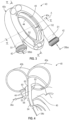
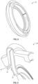
- the entire set of 40 volutes is shown in the figure 3 and cut to the figures 2 , 4 , 5a and 5b .
- the assembly 40 comprises two volutes 40a, 40b which are here joined and coaxial.
- Each volute 40a, 40b comprises a conduit wound in a spiral around an axis which is here the axis A, preferably over at least 360° so that the conduit makes at least one turn on itself.
- Each volute 40a, 40b comprises a first port 42 located at the external periphery of the duct and oriented in a tangential direction, and a second port 44 located at the internal periphery of the duct and oriented in a substantially radial direction.
- the passage section of the duct evolves over its circumference, preferably progressively.
- the passage section is maximum S1 at the first port 42 of each volute 40a, 40b and minimum S2 at the circumferential end of the duct opposite the first port 42.
- the set of volutes 40 is connected to the diffuser 34, to the rectifier 36 and to the exchanger 38 in the following manner.
- the volute 40a has its second port 44 which is connected to the outlet 34b of the diffuser 34 and its first port 42 which supplies the inlet 38ba of the second circuit 38b of the exchanger 38.
- the outlet 38bb of this second circuit 38b is connected to the first port 42 of the second volute 40b whose second port 44 is connected to the inlet 36a of the rectifier 36.
- the volute 40a is located upstream of the volute 40b.
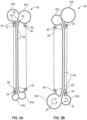
- the volutes 40a, 40b each have a passage section of circular or oval shape, preferably over their entire circumferential extent.
- oval shape we mean any elliptical or ovoid shape, or even oblong. Other shapes are however conceivable.
- the volutes 40a, 40b are joined and, preferably, are not nested one inside the other so as to limit the heat exchanges between the air flows circulating simultaneously in the two volutes.
- the angle ⁇ is defined as being the minimum angle around which the section of the volute extends (see Figure 5B ). This angle is at least equal to 220° and preferably tends as much as possible towards 360°.
- the volutes 40a, 40b extend around and at a distance from the casing 29 and are fixed to the latter by clamping, as will be detailed below.
- the plane P is defined as being a junction plane of the volutes 40a, 40b, this plane passing between the volutes and being perpendicular to the axis A.
- the plane P extends here just upstream of the diffuser 34.
- each volute 40a, 40b comprises an annular skin which defines the aforementioned passage section and which has a substantially constant thickness, both over its circumferential extent around the axis A but also over its entire extent when considering an axial section of the duct, as visible in the figure. figure 2 For example.
- a first annular boss 46 is located at the inner periphery of the volute 40a and comprises blind and tapped holes 48 for screwing screws 50.
- a second annular boss 52 is located at the inner periphery of the volute 40b and comprises blind and tapped holes 54 for screwing screws 56.
- the bosses 46, 50 are applied against annular flanges 58 of the casing 29 or of another external casing of the turbomachine, these flanges 58 comprising orifices for the passage of the screws 50, 56.
- the screws 50, 56 are oriented axially and regularly spaced around the axis A.
- the volutes 40a, 40b are thus fixed by clamping.
- the volutes 40a, 40b have reversed winding directions so that their ports 42 are formed by portions of conduits spaced apart from each other.
- the ports 42 are independent of each other and are at a distance and for example substantially diametrically opposed relative to the axis A.
- each duct is located at a larger section of the other duct.
- the maximum section S1 of each duct is located at a smaller section of the other duct. This can be seen in figure 3 notably.
- the ports 42 each have a generally tubular shape and are coupled respectively to the inlet 38ba and outlet 38bb of the exchanger 38 by suitable means.
- each volute 40a, 40b comprises two annular walls 60, 62 extending around the axis A and defining between them an air passage vein.
- the walls 60, 62 are substantially parallel and extend radially inwardly from the junction plane P of the volutes and from the annular skins of these volutes.
- the walls 60, 62 are frustoconical and converge from upstream to downstream radially inwardly. The walls 60, 62 are therefore inclined relative to the plane P.
- the set of volutes 40 is formed from a single piece.
- the volutes 40a, 40b and their ports 42, 44 are therefore formed from a single piece.
- the walls 60, 62 of the volute 40a have free ends opposite the duct, which define a connector 64 oriented substantially radially for connection to the outlet 34b of the diffuser 34.
- This connector 64 has an annular shape and can be fixed by screws or the like to the casing 29 or to another casing of the turbomachine.
- the walls 60, 62 of the volute 40b have free ends opposite the conduit, which define a connector 66 oriented substantially axially for connection to the inlet 36a of the rectifier 36.
- This connector 66 has an annular shape and can be attached to the boss 52 and fixed by means of this boss to the casing 29.
- the walls 60, 62 have a thickness similar or identical to that of the skins of the conduits.
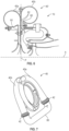
- FIG 6 illustrates another embodiment of an aircraft turbomachine 10 according to the invention, which differs from the embodiment of the figure 2 mainly by its set of 40' volutes.
- a first difference between these embodiments concerns the fact that the set of 40' volutes of the figure 6 consists of two adjacent annular pieces, each piece having a volute with its duct and ports 42, 44, as well as its walls 60, 62.
- the walls 62 of the ports 44 are therefore not merged but are on the contrary independent and applied one to the other.
- the walls 62 extend here in the junction plane P of the volutes.
- the walls 60, 62 are parallel to each other and to the plane P.
- the plane P extends here just downstream of the diffuser 34.
- the scrolls of the figure 6 are further downstream.
- the diffuser 36 could have, not a generally cylindrical shape with axial inlet 36a and outlet 36b, but rather a generally truncated cone shape whose inlet would be oriented axially but the outlet would be oriented radially inwards and therefore in the direction of the axis A.
- the volutes could be covered with a thermally insulating layer.
- This layer could be inserted between the two walls 62 of the variant embodiment of the figure 6 for example.
- This layer could be formed by an insulating material or even air.
- the present invention also relates to a method of manufacturing an aircraft turbomachine.
- a turbomachine can be a conventional cycle or a recuperated cycle and the present method proposes to manufacture the turbomachine according to the manufacturer's choice among these cycles.
- the method thus comprises a first step a) of determining the cycle of the turbomachine, from among a conventional cycle and a recovered cycle.
- the method then comprises a second step b1) or b2) which depends on the choice of the first step.
- step b1) consists of connecting the outlet 34b of the diffuser 34 to the inlet 36a of the rectifier 36 within the framework of the turbomachine 10 of the figure 2 Or 6 .
- the output of the diffuser 34 can be directly connected to the input 36a of the rectifier 36, as in the example shown in Figures 8 and 9 .
- THE direct connection is here made by an annular element 70 which extends around the axis A and defines an air passage vein 72 having a general U shape in axial section (cf. figure 9 ).
- This element 70 comprises a first annular connector 72 which is oriented radially inwards relative to the axis A and which is connected to the outlet 34b of the diffuser 34, and a second annular connector 74 which is oriented substantially axially and which is connected to the inlet 36a of the rectifier 36.
- the first and second connectors 72, 74 are respectively located at the ends of the U-shaped vein.
- the element 70 can be fixed by clamping to the casing 29 for example.
- step b2) consists of equipping the turbomachine with the set of volutes 40 described above, or even also with a heat exchanger 38 if this is not already the case.
- the ports 42, 42 of the volutes 40a, 40b are connected to the inlet 36a of the diffuser, to the outlet 34b of the rectifier 34 and to the exchanger 38, as mentioned above.
- the method comprises a next step consisting of connecting the ports 42 of the volutes 40a, 40b to each other by a bypass pipe 80, as illustrated in figure 7 .
Landscapes
- Engineering & Computer Science (AREA)
- Mechanical Engineering (AREA)
- General Engineering & Computer Science (AREA)
- Chemical & Material Sciences (AREA)
- Combustion & Propulsion (AREA)
- Physics & Mathematics (AREA)
- Thermal Sciences (AREA)
- Structures Of Non-Positive Displacement Pumps (AREA)
Claims (12)
- Turbotriebwerk (10) eines Luftfahrzeugs, umfassend:- einen Zentrifugalkompressor (14), der sich um eine Achse A erstreckt,
eine ringförmige Brennkammer (24), die sich um die Achse A erstreckt,- ein System (32) zur Verbreitung und zur Aufrichtung eines aus dem Zentrifugalkompressor heraustretenden Luftstroms zur Speisung der Brennkammer, wobei dieses System umfasst:- einen ringförmigen Verteiler (34), der im Wesentlichen radial ausgerichtet ist und der einen durch den Zentrifugalkompressor gespeisten Eingang (34a) umfasst, und- einen ringförmigen Gleichrichter (36), der einen Ausgang (36b) umfasst, um die Brennkammer zu speisen, und- einen Wärmetauscher (38), wobei dieser Tauscher umfasst:dadurch gekennzeichnet, dass die Spiralen (40a, 40b) entgegengesetzte Wickelrichtungen aufweisen, sodass ihre ersten Anschlüsse (42) durch Leitungsteile gebildet werden, die voneinander beabstandet sind, und dadurch, dass sich der minimale Abschnitt (S2) jeder Leitung an einem größeren Abschnitt der anderen Leitung befindet.- einen ersten Kreislauf (38a), der mit Abgas von dem Turbotriebwerk gespeist wird, und- einen zweiten Kreislauf (38b), der einen Eingang (38ba), der durch eine erste Spirale (40a) mit einem Ausgang (34b) des Verteilers (34) verbunden ist, und einen Ausgang (38bb) umfasst, der durch eine zweite Spirale (40b) mit einem Eingang (36a) des Gleichrichters (36) verbunden ist, wobei die erste und die zweite Spirale aneinandergefügt sind und jeweils eine ringförmige Leitung umfassen, die um die Achse A gewickelt ist und mit einem ersten Anschluss (42) verbunden ist, der sich am Außenumfang der Leitung befindet und in tangentialer Richtung ausgerichtet ist, und einen zweiten Anschluss (44), der sich am Innenumfang der Leitung befindet und in radialer Richtung ausgerichtet ist, wobei die Leitung jeder der Spiralen einen Durchgangsabschnitt umfasst, der evolutiv ist und der am ersten Anschluss maximal (S1) ist und an einem Umfangsende der Leitung gegenüber dem ersten Anschluss minimal (S2) ist, - Turbotriebwerk (10) nach Anspruch 1, wobei jede der Spiralen (40A, 40b) Durchgangsabschnitte mit kreisförmiger oder ovaler Form über einen Winkel (P) von mindestens 220° aufweist.
- Turbotriebwerk (10) nach Anspruch 1 oder 2, wobei der zweite Anschluss (44) jeder Spirale (40a, 40b) zwei ringförmige Wände (60, 62) umfasst, die sich um die Achse A erstrecken und untereinander eine Luftdurchgangsader definieren.
- Turbotriebwerk (10) nach Anspruch 3, wobei die zwei Wände (60, 62) des zweiten Anschlusses (44) im Wesentlichen parallel sind und sich ausgehend von einer ringförmigen Verkleidung der Spirale hervorstehend erstrecken, wobei diese Verkleidung sich um die Achse A erstreckt und im axialen Querschnitt eine kreisförmige oder ovale Form aufweist, um die Leitung zu bilden.
- Turbotriebwerk (10) nach Anspruch 4, wobei eine der Wände (62) des zweiten Anschlusses (44) der ersten Spirale (40a) mit einer der Wände (62) des zweiten Anschlusses (44) der zweiten Spirale (40b) zusammenfällt.
- Turbotriebwerk (10) nach Anspruch 4 oder 5, wobei die Wände (60, 62) des zweiten Anschlusses (44) der ersten Spirale (40a) freie Enden gegenüber der Verkleidung aufweisen, die ein im Wesentlichen radial ausgerichtetes Verbindungsstück (64) zur Verbindung mit dem Ausgang (34b) des Verteilers (34) definieren, und die Wände (60, 62) des zweiten Anschlusses (44) der zweiten Spirale (40b) freie Enden gegenüber der Verschalung aufweisen, die ein im Wesentlichen axial ausgerichtetes Verbindungsstück (66) zur Verbindung mit dem Eingang (36a) des Gleichrichters (36) definieren.
- Turbotriebwerk (10) nach einem der Ansprüche 4 bis 6, wobei die Wände (60, 62) der zweiten Anschlüsse (44) ebene und zur Achse A senkrechte Formen aufweisen oder kegelförmige Formen aufweisen, die von stromaufwärts nach stromabwärts nach innen konvergieren.
- Turbotriebwerk (10) nach einem der Ansprüche 4 bis 7, wobei die Verkleidung und die Wände (60, 62) im Wesentlichen eine gleiche Dicke aufweisen.
- Turbotriebwerk (10) nach einem der vorstehenden Ansprüche, wobei es weiter ein Außengehäuse (29) umfasst, das sich um die Achse A erstreckt und die Brennkammer (24) umgibt, wobei die Spiralen (40a, 40b) vom Gehäuse (29) beabstandet sind und durch Flansche an diesem Letzteren befestigt sind.
- Spiralenanordnung für ein Turbotriebwerk (10) nach einem der vorstehenden Ansprüche, wobei diese Anordnung erste und zweite Spiralen (40a, 40b) umfasst, die zusammengefügt sind und jeweils eine ringförmige Leitung umfasst, die um die Achse A gewickelt ist und mit einem ersten Anschluss (42) verbunden ist, der sich am Außenumfang der Leitung befindet und in tangentialer Richtung ausgerichtet ist, und einen zweiten Anschluss (44), der sich am Innenumfang der Leitung befindet und in radialer Richtung ausgerichtet, wobei die Leitung jeder der Spiralen einen Durchgangsabschnitt aufweist, der evolutiv ist und der am ersten Anschluss maximal (S1) ist und an einem Umfangsende der dem ersten Anschluss gegenüberliegenden Leitung minimal (S2) ist, dadurch gekennzeichnet, dass die Spiralen (40, 40b) entgegengesetzte Wickelrichtungen aufweisen, sodass ihre ersten Anschlüsse (42) durch Leitungsteile gebildet werden, die voneinander beabstandet sind, und dadurch, dass der minimale Abschnitt (S2) sich an einem größeren Abschnitt der anderen Leitung befindet.
- Anordnung nach Anspruch 10, wobei die ersten Anschlüsse (42) der Spiralen (40a, 40b) durch eine Umgehungsleitung (80) miteinander verbunden sind.
- Verfahren zur Herstellung eines Turbotriebwerks (10) eines Luftfahrzeugs, wobei dieses Turbotriebwerk umfasst:- einen Zentrifugalkompressor (14), der sich um eine Achse A erstreckt,
eine ringförmige Brennkammer (24), die sich um die Achse A erstreckt,- ein System (32) zur Verbreitung und zur Aufrichtung eines aus dem Zentrifugalkompressor heraustretenden Luftstroms zur Speisung der Brennkammer, wobei dieses System umfasst:- einen ringförmigen Verteiler (34), der im Wesentlichen radial ausgerichtet ist und der einen durch den Zentrifugalkompressor gespeisten Eingang (34a) umfasst, und- einen ringförmigen Gleichrichter (36), der einen Ausgang (36b) umfasst, um die Brennkammer zu speisen,dadurch gekennzeichnet, dass es die Schritte umfasst, die aus Folgendem bestehen:a) Bestimmen eines Zyklus des Turbotriebwerks aus einem klassischen Zyklus und einem wiederhergestellten Zyklus, undb2) im Falle eines wiederhergestellten Zyklus, Ausrüsten des Turbotriebwerks mit einer Spiralenanordnung (40) nach Abschnitt 10 oder 11, wobei der zweite Anschluss (44) einer ersten der Spiralen (40a) mit dem Ausgang (34b) des Verteilers (34) verbunden ist und der zweite Anschluss (44) der zweiten der Spiralen (40b) mit dem Eingang (36a) des Gleichrichters (36) verbunden ist.
Applications Claiming Priority (2)
| Application Number | Priority Date | Filing Date | Title |
|---|---|---|---|
| FR2006309A FR3111666B1 (fr) | 2020-06-17 | 2020-06-17 | Turbomachine d’aeronef a cycle recupere |
| PCT/FR2021/051075 WO2021255383A1 (fr) | 2020-06-17 | 2021-06-15 | Turbomachine d'aeronef a cycle recupere |
Publications (2)
| Publication Number | Publication Date |
|---|---|
| EP4168658A1 EP4168658A1 (de) | 2023-04-26 |
| EP4168658B1 true EP4168658B1 (de) | 2024-11-20 |
Family
ID=72470535
Family Applications (1)
| Application Number | Title | Priority Date | Filing Date |
|---|---|---|---|
| EP21737729.0A Active EP4168658B1 (de) | 2020-06-17 | 2021-06-15 | Flugzeugturbomaschine mit wiedergewonnenem zyklus |
Country Status (5)
| Country | Link |
|---|---|
| US (1) | US12286926B2 (de) |
| EP (1) | EP4168658B1 (de) |
| CN (1) | CN115867723A (de) |
| FR (1) | FR3111666B1 (de) |
| WO (1) | WO2021255383A1 (de) |
Families Citing this family (4)
| Publication number | Priority date | Publication date | Assignee | Title |
|---|---|---|---|---|
| FR3135111B1 (fr) * | 2022-04-29 | 2024-09-20 | Safran Helicopter Engines | Turbomoteur comprenant un echangeur de chaleur |
| FR3138830B1 (fr) | 2022-08-10 | 2024-06-28 | Safran Helicopter Engines | Turbomachine d’aeronef a cycle recupere |
| FR3149346B1 (fr) | 2023-06-01 | 2025-10-03 | Safran Power Units | Turbomachine d’aeronef a cycle recupere |
| FR3156834B1 (fr) | 2023-12-13 | 2025-11-28 | Safran Helicopter Engines | Turbomachine d’aeronef a cycle recupere |
Family Cites Families (20)
| Publication number | Priority date | Publication date | Assignee | Title |
|---|---|---|---|---|
| CH248924A (de) * | 1945-03-02 | 1947-05-31 | Berger Hans | Abgasturbolader. |
| US2801043A (en) * | 1954-08-24 | 1957-07-30 | Thompson Prod Inc | Turbine supercharger |
| CH577632A5 (de) * | 1974-07-09 | 1976-07-15 | Charmilles Sa Ateliers | |
| US4040249A (en) * | 1975-06-24 | 1977-08-09 | Deere & Company | Single shaft gas turbine engine with axially mounted disk regenerator |
| US4181466A (en) * | 1977-03-17 | 1980-01-01 | Wallace Murray Corp. | Centrifugal compressor and cover |
| US4936097A (en) * | 1988-11-07 | 1990-06-26 | Sundstrand Corporation | Turbocharger-gas turbine |
| US4981018A (en) * | 1989-05-18 | 1991-01-01 | Sundstrand Corporation | Compressor shroud air bleed passages |
| GB9415436D0 (en) * | 1994-07-30 | 1994-09-21 | Provost Michael J | Auxiliary gas turbine engines |
| US7334411B2 (en) * | 2004-04-21 | 2008-02-26 | General Electric Company | Gas turbine heat exchanger assembly and method for fabricating same |
| US9091275B2 (en) * | 2009-09-03 | 2015-07-28 | Honeywell International Inc. | Integrated EGR mixer and ported shroud housing compressor |
| US8240370B2 (en) * | 2009-12-18 | 2012-08-14 | Air Products And Chemicals, Inc. | Integrated hydrogen production and hydrocarbon extraction |
| JP2012057592A (ja) * | 2010-09-13 | 2012-03-22 | Ihi Corp | 固定翼式ターボチャージャ |
| FR3005109B1 (fr) * | 2013-04-30 | 2015-04-10 | Eurocopter France | Volute a deux volumes pour turbine a gaz |
| CN203346357U (zh) * | 2013-06-21 | 2013-12-18 | 中国电力工程顾问集团西北电力设计院 | 一种用于igcc电站的合成气显热回收系统 |
| US9303650B2 (en) * | 2013-06-24 | 2016-04-05 | Ford Global Technologies, Llc | Introduction of exhaust gas recirculation at a compressor blade trailing edge |
| JP6213322B2 (ja) * | 2014-03-18 | 2017-10-18 | トヨタ自動車株式会社 | 内燃機関 |
| EP3421759A1 (de) * | 2015-12-04 | 2019-01-02 | Jetoptera, Inc. | Mikroturbinengasgenerator und antriebssystem |
| CN105715381B (zh) * | 2016-01-28 | 2017-04-19 | 中国科学院工程热物理研究所 | 一种碟式换热器 |
| WO2018175678A1 (en) * | 2017-03-24 | 2018-09-27 | Borgwarner Inc. | Dual volute turbocharger with asymmetric tongue-to-wheel spacing |
| US10502424B2 (en) * | 2017-08-10 | 2019-12-10 | General Electric Company | Volute combustor for gas turbine engine |
-
2020
- 2020-06-17 FR FR2006309A patent/FR3111666B1/fr active Active
-
2021
- 2021-06-15 CN CN202180042765.XA patent/CN115867723A/zh active Pending
- 2021-06-15 EP EP21737729.0A patent/EP4168658B1/de active Active
- 2021-06-15 WO PCT/FR2021/051075 patent/WO2021255383A1/fr not_active Ceased
- 2021-06-15 US US18/001,441 patent/US12286926B2/en active Active
Also Published As
| Publication number | Publication date |
|---|---|
| FR3111666A1 (fr) | 2021-12-24 |
| WO2021255383A1 (fr) | 2021-12-23 |
| US20230220800A1 (en) | 2023-07-13 |
| CN115867723A (zh) | 2023-03-28 |
| FR3111666B1 (fr) | 2022-08-05 |
| US12286926B2 (en) | 2025-04-29 |
| EP4168658A1 (de) | 2023-04-26 |
Similar Documents
| Publication | Publication Date | Title |
|---|---|---|
| EP4168658B1 (de) | Flugzeugturbomaschine mit wiedergewonnenem zyklus | |
| EP1862644B1 (de) | Leitvorrichtung für den Luftstrom in einem Strahltriebwerk, und enstprechendes Strahltriebwerk und Diffusor | |
| EP2821597B1 (de) | Trennkante mit Blech zur Bildung einer Fläche zur Strömungsleitung und eines Enteisungskanals | |
| EP1881180B1 (de) | Wandbelüftungssystem für die Brennkammer | |
| EP2026006A1 (de) | Strömungsmaschine mit Diffusor | |
| EP4168659B1 (de) | Flugzeugturbomaschine mit wiedergewonnenem zyklus | |
| FR3054263A1 (fr) | Carter intermediaire de turbomachine d'aeronef realise d'une seule piece de fonderie avec une canalisation de lubrifiant | |
| WO2019239064A1 (fr) | Distributeur de turbine pour turbomachine, comprenant un système passif de réintroduction de gaz de fuite dans une veine d'écoulement des gaz | |
| FR3119199A1 (fr) | Conduit de decharge a etancheite perfectionnee | |
| WO2024246459A1 (fr) | Turbomachine d'aeronef a cycle recupere | |
| EP3673154A1 (de) | Ausgabekanal einer zwischengehäusenabe für ein flugzeugturbostrahltriebwerk mit kühlkanälen | |
| EP3983652B1 (de) | Ringförmiges bauteil zur lagerung eines turbinenmotorlagers | |
| WO2022208018A1 (fr) | Dispositif d'etancheite et de reinjection d'un flux de contournement pour distributeur de turbine | |
| FR3138830A1 (fr) | Turbomachine d’aeronef a cycle recupere | |
| FR3109795A1 (fr) | Carter intermediaire de redressement avec bras structural monobloc | |
| EP4441341B1 (de) | Servicearm für ein turbomaschinenabgasgehäuse | |
| FR3092135A1 (fr) | Turbomachine, telle qu’un turboreacteur d’avion | |
| WO2026052916A1 (fr) | Module pour une turbomachine d'aeronef | |
| FR3015588A1 (fr) | Turbomachine a double compresseur centrifuge | |
| FR3025260B1 (fr) | Compresseur centrifuge a resistance amelioree | |
| WO2025125743A1 (fr) | Turbomachine d'aeronef a cycle recupere | |
| FR3064295A1 (fr) | Carter intermediaire de turbomachine d'aeronef comprenant un embout de passage de lubrifiant solidaire d'une plateforme | |
| WO2025068641A1 (fr) | Dispositif pour le centrage et le guidage en rotation d'un arbre de turbomachine à lubrification optimisée d'éléments de roulement par du lubrifiant évacué depuis un sfd | |
| FR3147834A1 (fr) | Ensemble rotorique de turbine pour turbomachine | |
| FR3015566A1 (fr) | Turbomachine a double turbine axiale |
Legal Events
| Date | Code | Title | Description |
|---|---|---|---|
| STAA | Information on the status of an ep patent application or granted ep patent |
Free format text: STATUS: UNKNOWN |
|
| STAA | Information on the status of an ep patent application or granted ep patent |
Free format text: STATUS: THE INTERNATIONAL PUBLICATION HAS BEEN MADE |
|
| PUAI | Public reference made under article 153(3) epc to a published international application that has entered the european phase |
Free format text: ORIGINAL CODE: 0009012 |
|
| STAA | Information on the status of an ep patent application or granted ep patent |
Free format text: STATUS: REQUEST FOR EXAMINATION WAS MADE |
|
| 17P | Request for examination filed |
Effective date: 20230111 |
|
| AK | Designated contracting states |
Kind code of ref document: A1 Designated state(s): AL AT BE BG CH CY CZ DE DK EE ES FI FR GB GR HR HU IE IS IT LI LT LU LV MC MK MT NL NO PL PT RO RS SE SI SK SM TR |
|
| DAV | Request for validation of the european patent (deleted) | ||
| DAX | Request for extension of the european patent (deleted) | ||
| REG | Reference to a national code |
Ref country code: DE Ref legal event code: R079 Free format text: PREVIOUS MAIN CLASS: F02C0003100000 Ipc: F04D0017120000 Ref document number: 602021022111 Country of ref document: DE |
|
| GRAP | Despatch of communication of intention to grant a patent |
Free format text: ORIGINAL CODE: EPIDOSNIGR1 |
|
| STAA | Information on the status of an ep patent application or granted ep patent |
Free format text: STATUS: GRANT OF PATENT IS INTENDED |
|
| RIC1 | Information provided on ipc code assigned before grant |
Ipc: F04D 29/44 20060101ALI20240610BHEP Ipc: F04D 29/58 20060101ALI20240610BHEP Ipc: F04D 25/04 20060101ALI20240610BHEP Ipc: F02C 7/08 20060101ALI20240610BHEP Ipc: F01D 9/02 20060101ALI20240610BHEP Ipc: F04D 29/42 20060101ALI20240610BHEP Ipc: F02C 3/10 20060101ALI20240610BHEP Ipc: F04D 17/12 20060101AFI20240610BHEP |
|
| INTG | Intention to grant announced |
Effective date: 20240702 |
|
| RAP3 | Party data changed (applicant data changed or rights of an application transferred) |
Owner name: SAFRAN HELICOPTER ENGINES |
|
| GRAS | Grant fee paid |
Free format text: ORIGINAL CODE: EPIDOSNIGR3 |
|
| GRAA | (expected) grant |
Free format text: ORIGINAL CODE: 0009210 |
|
| STAA | Information on the status of an ep patent application or granted ep patent |
Free format text: STATUS: THE PATENT HAS BEEN GRANTED |
|
| AK | Designated contracting states |
Kind code of ref document: B1 Designated state(s): AL AT BE BG CH CY CZ DE DK EE ES FI FR GB GR HR HU IE IS IT LI LT LU LV MC MK MT NL NO PL PT RO RS SE SI SK SM TR |
|
| REG | Reference to a national code |
Ref country code: GB Ref legal event code: FG4D Free format text: NOT ENGLISH |
|
| REG | Reference to a national code |
Ref country code: CH Ref legal event code: EP |
|
| REG | Reference to a national code |
Ref country code: DE Ref legal event code: R096 Ref document number: 602021022111 Country of ref document: DE |
|
| REG | Reference to a national code |
Ref country code: IE Ref legal event code: FG4D Free format text: LANGUAGE OF EP DOCUMENT: FRENCH |
|
| REG | Reference to a national code |
Ref country code: LT Ref legal event code: MG9D |
|
| REG | Reference to a national code |
Ref country code: NL Ref legal event code: MP Effective date: 20241120 |
|
| PG25 | Lapsed in a contracting state [announced via postgrant information from national office to epo] |
Ref country code: HR Free format text: LAPSE BECAUSE OF FAILURE TO SUBMIT A TRANSLATION OF THE DESCRIPTION OR TO PAY THE FEE WITHIN THE PRESCRIBED TIME-LIMIT Effective date: 20241120 Ref country code: IS Free format text: LAPSE BECAUSE OF FAILURE TO SUBMIT A TRANSLATION OF THE DESCRIPTION OR TO PAY THE FEE WITHIN THE PRESCRIBED TIME-LIMIT Effective date: 20250320 Ref country code: PT Free format text: LAPSE BECAUSE OF FAILURE TO SUBMIT A TRANSLATION OF THE DESCRIPTION OR TO PAY THE FEE WITHIN THE PRESCRIBED TIME-LIMIT Effective date: 20250320 |
|
| PG25 | Lapsed in a contracting state [announced via postgrant information from national office to epo] |
Ref country code: FI Free format text: LAPSE BECAUSE OF FAILURE TO SUBMIT A TRANSLATION OF THE DESCRIPTION OR TO PAY THE FEE WITHIN THE PRESCRIBED TIME-LIMIT Effective date: 20241120 Ref country code: NL Free format text: LAPSE BECAUSE OF FAILURE TO SUBMIT A TRANSLATION OF THE DESCRIPTION OR TO PAY THE FEE WITHIN THE PRESCRIBED TIME-LIMIT Effective date: 20241120 |
|
| REG | Reference to a national code |
Ref country code: AT Ref legal event code: MK05 Ref document number: 1743809 Country of ref document: AT Kind code of ref document: T Effective date: 20241120 |
|
| PG25 | Lapsed in a contracting state [announced via postgrant information from national office to epo] |
Ref country code: BG Free format text: LAPSE BECAUSE OF FAILURE TO SUBMIT A TRANSLATION OF THE DESCRIPTION OR TO PAY THE FEE WITHIN THE PRESCRIBED TIME-LIMIT Effective date: 20241120 |
|
| PG25 | Lapsed in a contracting state [announced via postgrant information from national office to epo] |
Ref country code: ES Free format text: LAPSE BECAUSE OF FAILURE TO SUBMIT A TRANSLATION OF THE DESCRIPTION OR TO PAY THE FEE WITHIN THE PRESCRIBED TIME-LIMIT Effective date: 20241120 |
|
| PG25 | Lapsed in a contracting state [announced via postgrant information from national office to epo] |
Ref country code: NO Free format text: LAPSE BECAUSE OF FAILURE TO SUBMIT A TRANSLATION OF THE DESCRIPTION OR TO PAY THE FEE WITHIN THE PRESCRIBED TIME-LIMIT Effective date: 20250220 |
|
| PG25 | Lapsed in a contracting state [announced via postgrant information from national office to epo] |
Ref country code: GR Free format text: LAPSE BECAUSE OF FAILURE TO SUBMIT A TRANSLATION OF THE DESCRIPTION OR TO PAY THE FEE WITHIN THE PRESCRIBED TIME-LIMIT Effective date: 20250221 Ref country code: AT Free format text: LAPSE BECAUSE OF FAILURE TO SUBMIT A TRANSLATION OF THE DESCRIPTION OR TO PAY THE FEE WITHIN THE PRESCRIBED TIME-LIMIT Effective date: 20241120 Ref country code: LV Free format text: LAPSE BECAUSE OF FAILURE TO SUBMIT A TRANSLATION OF THE DESCRIPTION OR TO PAY THE FEE WITHIN THE PRESCRIBED TIME-LIMIT Effective date: 20241120 |
|
| PG25 | Lapsed in a contracting state [announced via postgrant information from national office to epo] |
Ref country code: PL Free format text: LAPSE BECAUSE OF FAILURE TO SUBMIT A TRANSLATION OF THE DESCRIPTION OR TO PAY THE FEE WITHIN THE PRESCRIBED TIME-LIMIT Effective date: 20241120 |
|
| PG25 | Lapsed in a contracting state [announced via postgrant information from national office to epo] |
Ref country code: RS Free format text: LAPSE BECAUSE OF FAILURE TO SUBMIT A TRANSLATION OF THE DESCRIPTION OR TO PAY THE FEE WITHIN THE PRESCRIBED TIME-LIMIT Effective date: 20250220 |
|
| PG25 | Lapsed in a contracting state [announced via postgrant information from national office to epo] |
Ref country code: SM Free format text: LAPSE BECAUSE OF FAILURE TO SUBMIT A TRANSLATION OF THE DESCRIPTION OR TO PAY THE FEE WITHIN THE PRESCRIBED TIME-LIMIT Effective date: 20241120 |
|
| PGFP | Annual fee paid to national office [announced via postgrant information from national office to epo] |
Ref country code: DE Payment date: 20250618 Year of fee payment: 5 |
|
| PG25 | Lapsed in a contracting state [announced via postgrant information from national office to epo] |
Ref country code: DK Free format text: LAPSE BECAUSE OF FAILURE TO SUBMIT A TRANSLATION OF THE DESCRIPTION OR TO PAY THE FEE WITHIN THE PRESCRIBED TIME-LIMIT Effective date: 20241120 |
|
| PGFP | Annual fee paid to national office [announced via postgrant information from national office to epo] |
Ref country code: GB Payment date: 20250625 Year of fee payment: 5 |
|
| PG25 | Lapsed in a contracting state [announced via postgrant information from national office to epo] |
Ref country code: EE Free format text: LAPSE BECAUSE OF FAILURE TO SUBMIT A TRANSLATION OF THE DESCRIPTION OR TO PAY THE FEE WITHIN THE PRESCRIBED TIME-LIMIT Effective date: 20241120 |
|
| PGFP | Annual fee paid to national office [announced via postgrant information from national office to epo] |
Ref country code: FR Payment date: 20250620 Year of fee payment: 5 |
|
| PG25 | Lapsed in a contracting state [announced via postgrant information from national office to epo] |
Ref country code: RO Free format text: LAPSE BECAUSE OF FAILURE TO SUBMIT A TRANSLATION OF THE DESCRIPTION OR TO PAY THE FEE WITHIN THE PRESCRIBED TIME-LIMIT Effective date: 20241120 |
|
| PG25 | Lapsed in a contracting state [announced via postgrant information from national office to epo] |
Ref country code: SK Free format text: LAPSE BECAUSE OF FAILURE TO SUBMIT A TRANSLATION OF THE DESCRIPTION OR TO PAY THE FEE WITHIN THE PRESCRIBED TIME-LIMIT Effective date: 20241120 |
|
| PG25 | Lapsed in a contracting state [announced via postgrant information from national office to epo] |
Ref country code: CZ Free format text: LAPSE BECAUSE OF FAILURE TO SUBMIT A TRANSLATION OF THE DESCRIPTION OR TO PAY THE FEE WITHIN THE PRESCRIBED TIME-LIMIT Effective date: 20241120 |
|
| REG | Reference to a national code |
Ref country code: DE Ref legal event code: R097 Ref document number: 602021022111 Country of ref document: DE |
|
| PG25 | Lapsed in a contracting state [announced via postgrant information from national office to epo] |
Ref country code: SE Free format text: LAPSE BECAUSE OF FAILURE TO SUBMIT A TRANSLATION OF THE DESCRIPTION OR TO PAY THE FEE WITHIN THE PRESCRIBED TIME-LIMIT Effective date: 20241120 |
|
| PLBE | No opposition filed within time limit |
Free format text: ORIGINAL CODE: 0009261 |
|
| STAA | Information on the status of an ep patent application or granted ep patent |
Free format text: STATUS: NO OPPOSITION FILED WITHIN TIME LIMIT |
|
| PGFP | Annual fee paid to national office [announced via postgrant information from national office to epo] |
Ref country code: IT Payment date: 20250630 Year of fee payment: 5 |
|
| 26N | No opposition filed |
Effective date: 20250821 |
|
| REG | Reference to a national code |
Ref country code: CH Ref legal event code: H13 Free format text: ST27 STATUS EVENT CODE: U-0-0-H10-H13 (AS PROVIDED BY THE NATIONAL OFFICE) Effective date: 20260127 |
|
| PG25 | Lapsed in a contracting state [announced via postgrant information from national office to epo] |
Ref country code: MC Free format text: LAPSE BECAUSE OF FAILURE TO SUBMIT A TRANSLATION OF THE DESCRIPTION OR TO PAY THE FEE WITHIN THE PRESCRIBED TIME-LIMIT Effective date: 20241120 |
|
| PG25 | Lapsed in a contracting state [announced via postgrant information from national office to epo] |
Ref country code: LU Free format text: LAPSE BECAUSE OF NON-PAYMENT OF DUE FEES Effective date: 20250615 |
|
| REG | Reference to a national code |
Ref country code: BE Ref legal event code: MM Effective date: 20250630 |
|
| PG25 | Lapsed in a contracting state [announced via postgrant information from national office to epo] |
Ref country code: IE Free format text: LAPSE BECAUSE OF NON-PAYMENT OF DUE FEES Effective date: 20250615 |
|
| PG25 | Lapsed in a contracting state [announced via postgrant information from national office to epo] |
Ref country code: BE Free format text: LAPSE BECAUSE OF NON-PAYMENT OF DUE FEES Effective date: 20250630 |