EP4166814A1 - Timing belt tensioner with improved construction - Google Patents
Timing belt tensioner with improved construction Download PDFInfo
- Publication number
- EP4166814A1 EP4166814A1 EP22213079.1A EP22213079A EP4166814A1 EP 4166814 A1 EP4166814 A1 EP 4166814A1 EP 22213079 A EP22213079 A EP 22213079A EP 4166814 A1 EP4166814 A1 EP 4166814A1
- Authority
- EP
- European Patent Office
- Prior art keywords
- tensioner
- spring
- shaft
- arm
- base unit
- Prior art date
- Legal status (The legal status is an assumption and is not a legal conclusion. Google has not performed a legal analysis and makes no representation as to the accuracy of the status listed.)
- Pending
Links
- 238000010276 construction Methods 0.000 title 1
- 238000012546 transfer Methods 0.000 claims abstract description 25
- 238000013016 damping Methods 0.000 claims description 111
- 230000000750 progressive effect Effects 0.000 claims description 10
- 230000000295 complement effect Effects 0.000 claims description 7
- 230000005540 biological transmission Effects 0.000 claims description 4
- 239000003550 marker Substances 0.000 description 16
- 238000004519 manufacturing process Methods 0.000 description 5
- 238000000034 method Methods 0.000 description 5
- 230000035515 penetration Effects 0.000 description 3
- 239000007787 solid Substances 0.000 description 3
- 230000002401 inhibitory effect Effects 0.000 description 2
- 238000009434 installation Methods 0.000 description 2
- 239000000463 material Substances 0.000 description 2
- 238000005381 potential energy Methods 0.000 description 2
- 230000004044 response Effects 0.000 description 2
- 230000001360 synchronised effect Effects 0.000 description 2
- 239000004677 Nylon Substances 0.000 description 1
- 229920003189 Nylon 4,6 Polymers 0.000 description 1
- 229920003390 Stanyl® TW371 Polymers 0.000 description 1
- 230000004075 alteration Effects 0.000 description 1
- 230000009286 beneficial effect Effects 0.000 description 1
- 230000008901 benefit Effects 0.000 description 1
- 229920006351 engineering plastic Polymers 0.000 description 1
- 230000006872 improvement Effects 0.000 description 1
- 238000003780 insertion Methods 0.000 description 1
- 230000037431 insertion Effects 0.000 description 1
- 238000012986 modification Methods 0.000 description 1
- 230000004048 modification Effects 0.000 description 1
- 229920001778 nylon Polymers 0.000 description 1
- 229920000642 polymer Polymers 0.000 description 1
- 230000036316 preload Effects 0.000 description 1
- 230000008569 process Effects 0.000 description 1
- 238000005096 rolling process Methods 0.000 description 1
- 230000035939 shock Effects 0.000 description 1
- 238000012360 testing method Methods 0.000 description 1
Images


Classifications
-
- F—MECHANICAL ENGINEERING; LIGHTING; HEATING; WEAPONS; BLASTING
- F16—ENGINEERING ELEMENTS AND UNITS; GENERAL MEASURES FOR PRODUCING AND MAINTAINING EFFECTIVE FUNCTIONING OF MACHINES OR INSTALLATIONS; THERMAL INSULATION IN GENERAL
- F16H—GEARING
- F16H7/00—Gearings for conveying rotary motion by endless flexible members
- F16H7/08—Means for varying tension of belts, ropes, or chains
- F16H7/10—Means for varying tension of belts, ropes, or chains by adjusting the axis of a pulley
- F16H7/12—Means for varying tension of belts, ropes, or chains by adjusting the axis of a pulley of an idle pulley
- F16H7/1209—Means for varying tension of belts, ropes, or chains by adjusting the axis of a pulley of an idle pulley with vibration damping means
- F16H7/1218—Means for varying tension of belts, ropes, or chains by adjusting the axis of a pulley of an idle pulley with vibration damping means of the dry friction type
-
- F—MECHANICAL ENGINEERING; LIGHTING; HEATING; WEAPONS; BLASTING
- F01—MACHINES OR ENGINES IN GENERAL; ENGINE PLANTS IN GENERAL; STEAM ENGINES
- F01L—CYCLICALLY OPERATING VALVES FOR MACHINES OR ENGINES
- F01L1/00—Valve-gear or valve arrangements, e.g. lift-valve gear
- F01L1/02—Valve drive
- F01L1/024—Belt drive
-
- F—MECHANICAL ENGINEERING; LIGHTING; HEATING; WEAPONS; BLASTING
- F16—ENGINEERING ELEMENTS AND UNITS; GENERAL MEASURES FOR PRODUCING AND MAINTAINING EFFECTIVE FUNCTIONING OF MACHINES OR INSTALLATIONS; THERMAL INSULATION IN GENERAL
- F16H—GEARING
- F16H7/00—Gearings for conveying rotary motion by endless flexible members
- F16H7/08—Means for varying tension of belts, ropes, or chains
- F16H7/0829—Means for varying tension of belts, ropes, or chains with vibration damping means
- F16H7/0831—Means for varying tension of belts, ropes, or chains with vibration damping means of the dry friction type
-
- F—MECHANICAL ENGINEERING; LIGHTING; HEATING; WEAPONS; BLASTING
- F16—ENGINEERING ELEMENTS AND UNITS; GENERAL MEASURES FOR PRODUCING AND MAINTAINING EFFECTIVE FUNCTIONING OF MACHINES OR INSTALLATIONS; THERMAL INSULATION IN GENERAL
- F16H—GEARING
- F16H7/00—Gearings for conveying rotary motion by endless flexible members
- F16H7/08—Means for varying tension of belts, ropes, or chains
- F16H2007/0802—Actuators for final output members
- F16H2007/081—Torsion springs
-
- F—MECHANICAL ENGINEERING; LIGHTING; HEATING; WEAPONS; BLASTING
- F16—ENGINEERING ELEMENTS AND UNITS; GENERAL MEASURES FOR PRODUCING AND MAINTAINING EFFECTIVE FUNCTIONING OF MACHINES OR INSTALLATIONS; THERMAL INSULATION IN GENERAL
- F16H—GEARING
- F16H7/00—Gearings for conveying rotary motion by endless flexible members
- F16H7/08—Means for varying tension of belts, ropes, or chains
- F16H2007/0842—Mounting or support of tensioner
- F16H2007/0844—Mounting elements essentially within boundaries of final output members
-
- F—MECHANICAL ENGINEERING; LIGHTING; HEATING; WEAPONS; BLASTING
- F16—ENGINEERING ELEMENTS AND UNITS; GENERAL MEASURES FOR PRODUCING AND MAINTAINING EFFECTIVE FUNCTIONING OF MACHINES OR INSTALLATIONS; THERMAL INSULATION IN GENERAL
- F16H—GEARING
- F16H7/00—Gearings for conveying rotary motion by endless flexible members
- F16H7/08—Means for varying tension of belts, ropes, or chains
- F16H2007/0846—Means for varying tension of belts, ropes, or chains comprising a mechanical stopper
-
- F—MECHANICAL ENGINEERING; LIGHTING; HEATING; WEAPONS; BLASTING
- F16—ENGINEERING ELEMENTS AND UNITS; GENERAL MEASURES FOR PRODUCING AND MAINTAINING EFFECTIVE FUNCTIONING OF MACHINES OR INSTALLATIONS; THERMAL INSULATION IN GENERAL
- F16H—GEARING
- F16H7/00—Gearings for conveying rotary motion by endless flexible members
- F16H7/08—Means for varying tension of belts, ropes, or chains
- F16H2007/0863—Finally actuated members, e.g. constructional details thereof
- F16H2007/0865—Pulleys
-
- F—MECHANICAL ENGINEERING; LIGHTING; HEATING; WEAPONS; BLASTING
- F16—ENGINEERING ELEMENTS AND UNITS; GENERAL MEASURES FOR PRODUCING AND MAINTAINING EFFECTIVE FUNCTIONING OF MACHINES OR INSTALLATIONS; THERMAL INSULATION IN GENERAL
- F16H—GEARING
- F16H7/00—Gearings for conveying rotary motion by endless flexible members
- F16H7/08—Means for varying tension of belts, ropes, or chains
- F16H2007/0889—Path of movement of the finally actuated member
- F16H2007/0893—Circular path
-
- F—MECHANICAL ENGINEERING; LIGHTING; HEATING; WEAPONS; BLASTING
- F16—ENGINEERING ELEMENTS AND UNITS; GENERAL MEASURES FOR PRODUCING AND MAINTAINING EFFECTIVE FUNCTIONING OF MACHINES OR INSTALLATIONS; THERMAL INSULATION IN GENERAL
- F16H—GEARING
- F16H7/00—Gearings for conveying rotary motion by endless flexible members
- F16H7/08—Means for varying tension of belts, ropes, or chains
- F16H2007/0889—Path of movement of the finally actuated member
- F16H2007/0897—External to internal direction
-
- F—MECHANICAL ENGINEERING; LIGHTING; HEATING; WEAPONS; BLASTING
- F16—ENGINEERING ELEMENTS AND UNITS; GENERAL MEASURES FOR PRODUCING AND MAINTAINING EFFECTIVE FUNCTIONING OF MACHINES OR INSTALLATIONS; THERMAL INSULATION IN GENERAL
- F16H—GEARING
- F16H7/00—Gearings for conveying rotary motion by endless flexible members
- F16H7/18—Means for guiding or supporting belts, ropes, or chains
- F16H7/20—Mountings for rollers or pulleys
Abstract

Description
- This application claims the benefit of priority to
U.S. Provisional Patent Application No. 62/491,469 filed April 28, 2017 U.S. Provisional Patent Application No. 62/568,097 filed October 4, 2017 - This disclosure relates to tensioners and in particular tensioners that operate to tension synchronous endless drive members such as a timing belt on an engine.
- Tensioners are known devices for maintaining tension in belts (e.g. timing belts) or other endless drive members that are driven by an engine and that are used to drive certain components, such as camshafts. A tensioner typically includes a shaft-and-base unit that mounts to the engine, a tensioner arm that is pivotable with respect to the base about a pivot axis, a pulley that is mounted on the arm for engagement with the belt, and a spring that acts between the base and the arm to drive the arm into the belt. The direction into the belt (i.e. the direction in which the spring drives the arm) may be referred to as a direction towards a free arm position (i.e. towards a position that the tensioner arm would reach if no belt were present to stop it). This is a direction of lessening spring potential energy. The tensioner arm in general moves in this direction as the belt tension drops. The direction away from the belt (i.e. the direction against the biasing force of the spring) may be referred to as a direction towards a load stop position, and is a direction of increasing spring potential energy. The tensioner arm in general moves in this direction as the belt tension increases. It is known that it is desirable to provide damping on a tensioner in order to assist the tensioner arm in resisting being thrown off a belt (e.g. a timing belt) during sudden increases in belt tension which can accelerate the tensioner arm suddenly towards the load stop position. In at least some applications, however, it would be beneficial to provide a tensioner that is improved (e.g. more compact) than some other tensioners.
- In an aspect, a tensioner is provided for an endless drive member. The tensioner includes a shaft-and-base unit that is mountable to be stationary relative to an engine, a tensioner arm, a pulley, a bushing and a tensioner spring. The shaft-and-base unit includes a fastener aperture to permit a fastener to pass through to fixedly connect the shaft-and-base unit to the engine. The tensioner arm is pivotable relative to the shaft-and-base unit about a arm pivot axis. The tensioner arm has a first axial arm end and a second axial arm end. The tensioner arm has a radially outer surface that includes a pulley support surface, and which extends from the first axial arm end to the second axial arm end and is entirely free of any radial projections. The pulley is rotatably supported on the pulley support surface of the tensioner arm for rotation about a pulley axis that is offset from the tensioner arm axis, wherein the pulley is engageable with an endless drive member. The bushing is positioned radially between the shaft-and-base unit and the tensioner arm to support the tensioner arm radially on the shaft-and-base unit. The tensioner spring is positioned to urge the tensioner arm in a first direction about the tensioner arm axis.
- In another aspect, a tensioner is provided for an endless drive member, and includes a shaft-and-base unit that is mountable to be stationary relative to an engine, a tensioner arm, a pulley, a bushing and a tensioner spring and a damping carrier. The shaft-and-base unit includes a fastener aperture to permit a fastener to pass through to fixedly connect the shaft-and-base unit to the engine. The tensioner arm is pivotable relative to the shaft-and-base unit about a tensioner arm axis. The pulley is rotatably mounted to the tensioner arm for rotation about a pulley axis that is offset from the tensioner arm axis. The pulley is engageable with an endless drive member. The bushing is positioned radially between the shaft-and-base unit and the tensioner arm to support the tensioner arm radially on the shaft-and-base unit. The tensioner spring is positioned to urge the tensioner arm in a first direction about the tensioner arm axis. The tensioner spring is a torsion spring having a first end and a second end and a plurality of coils between the first and second ends. The first and second ends are pushed by the shaft-and-base unit and the tensioner arm respectively during torque transfer therebetween, so as to urge the coils to expand radially. The damping carrier includes a spring end engagement slot that is positioned to hold the second spring end. The damping carrier further includes a radially inner damping surface thereon. The second spring end and the radially inner damping surface are oriented relative to one another such that a tangential force from the tensioner arm on the tensioner spring at the second spring end results in a reaction force of the shaft-and-base unit on the radially inner damping surface, resulting in frictional damping during movement of the tensioner arm relative to the shaft-and-base unit about the arm pivot axis.
- In yet another aspect, a tensioner is provided for an endless drive member, and includes a shaft-and-base unit, a tensioner arm, a pulley and a tensioner spring. The shaft-and-base unit is mountable to be stationary relative to an engine. The shaft-and-base unit includes a fastener aperture to permit a fastener to pass through to fixedly connect the shaft-and-base unit to the engine. The tensioner arm is pivotable relative to the shaft-and-base unit about a tensioner arm axis. The pulley has an endless drive member engagement surface that is engageable with an endless drive member. The pulley is rotatably mounted to the tensioner arm for rotation about a pulley axis that is offset from the tensioner arm axis by an offset distance that is smaller than a radius of the pulley at the endless drive member engagement surface. The tensioner spring is positioned to urge the tensioner arm in a first direction relative to the shaft-and-base unit. The tensioner spring includes a plurality of coils spaced apart from one another by a coil-to-coil gap. A space to enter between any two adjacent ones of the plurality of coils of the tensioner spring is less than a width of each of the plurality of coils so as to inhibit the tensioner spring from entangling with another identical tensioner spring.
- In yet another aspect, a tensioner is provided for an endless drive member, and includes a shaft-and-base unit, a tensioner arm, a pulley, and a tensioner spring. The shaft-and-base unit is mountable to be stationary relative to an engine, and includes a fastener aperture to permit a fastener to pass through to fixedly connect the shaft-and-base unit to the engine. The tensioner arm is pivotable relative to the shaft-and-base unit about a tensioner arm axis. The pulley is rotatably mounted to the tensioner arm for rotation about a pulley axis that is offset from the tensioner arm axis. The pulley is engageable with an endless drive member. The tensioner spring is positioned to urge the tensioner arm in a first direction relative to the shaft-and-base unit. The tensioner spring includes a plurality of coils that are arranged generally helically about a longitudinal axis and are spaced radially from one another and generally increase in distance away from the axis in a longitudinal direction.
- In yet another aspect, a tensioner is provided for an endless drive member, and includes a shaft-and-base unit, a tensioner arm, a pulley, and a tensioner spring. The shaft-and-base unit is mountable to be stationary relative to an engine, and includes a fastener aperture to permit a fastener to pass through to fixedly connect the shaft-and-base unit to the engine. The shaft-and-base unit includes a base and a shaft that is separate from the base and has the base mounted thereon. The shaft has a shaft axis and has a first axial shaft end and a second axial shaft end. The shaft has a radially outer surface that includes an arm support surface and which extends from the first axial shaft end to the second axial shaft end and is entirely free of any radial projections. The tensioner arm is pivotably supported on the arm support surface of the shaft for pivoting movement about a tensioner arm axis. The pulley is rotatably mounted to the tensioner arm for rotation about a pulley axis that is offset from the tensioner arm axis, wherein the pulley is engageable with an endless drive member. The tensioner spring is positioned to urge the tensioner arm in a first direction relative to the shaft-and-base unit. The tensioner spring has a first end, a second end and a plurality of coils between the first and second ends. The first end is positioned to transfer torque with the base and the second end is positioned to transfer torque with the tensioner arm.
- In yet another aspect, a tensioner is provided for an endless drive member, and includes a shaft-and-base unit, a tensioner arm, a pulley, and a tensioner spring. The shaft-and-base unit is mountable to be stationary relative to an engine, and includes a fastener aperture to permit a fastener to pass through to fixedly connect the shaft-and-base unit to the engine. The shaft-and-base unit includes a base and a shaft that is separate from the base and has the base mounted thereon. The shaft has a shaft axis and has a first axial shaft end and a second axial shaft end. The shaft has a radially outer surface that includes an arm support surface and which extends from the first axial shaft end to the second axial shaft end and is entirely free of any radial projections. The tensioner arm is pivotably supported on the arm support surface of the shaft for pivoting movement about a tensioner arm axis. The pulley is rotatably mounted to the tensioner arm for rotation about a pulley axis that is offset from the tensioner arm axis, wherein the pulley is engageable with an endless drive member. The tensioner spring is positioned to urge the tensioner arm in a first direction relative to the shaft-and-base unit. The tensioner spring includes a plurality of coils that are arranged about a longitudinal axis such that the coils are radially offset from one another axially overlap one another. The plurality of coils includes a radially outermost coil and at least one inner coil. One of the tensioner arm and the shaft-and-base unit has a spring limit surface. As tension increases in the endless drive member, the tensioner spring progressively locks up by progressive expansion of the coils into engagement with one another and progressive expansion of the radially outermost coil into engagement with the spring limit surface.
- In yet another aspect, a tensioner is provided for an endless drive member, and includes a shaft-and-base unit, a tensioner arm, a pulley, and a tensioner spring. The shaft-and-base unit is mountable to be stationary relative to an engine. The shaft-and-base unit includes a fastener aperture to permit a fastener to pass through to fixedly connect the shaft-and-base unit to the engine. The tensioner arm is pivotable relative to the shaft-and-base unit about a tensioner arm axis. The pulley is rotatably mounted to the tensioner arm for rotation about a pulley axis that is offset from the tensioner arm axis, wherein the pulley is engageable with an endless drive member. The tensioner spring is positioned to urge the tensioner arm in a first direction relative to the shaft-and-base unit. The tensioner spring includes a plurality of coils that are arranged about a longitudinal axis such that the coils are radially offset from one another but axially overlap one another. The plurality of coils includes a radially outermost coil and at least one inner coil. One of the tensioner arm and the shaft-and-base unit has a spring limit surface. When the tension increases in the endless drive member to a selected tension, radial expansion of the plurality of coils is prevented by engagement of the plurality of coils with at least the spring limit surface.
- In yet another aspect, a tensioner for an endless drive member. The tensioner includes a shaft-and-base unit, a tensioner arm, a pulley, a tensioner spring and a damping carrier. The shaft-and-base unit is mountable to be stationary relative to an engine block. The tensioner arm is pivotable relative to the shaft-and-base unit about a tensioner arm axis. The pulley is rotatably mounted to the tensioner arm for rotation about a pulley axis that is offset from the tensioner arm axis. The pulley is engageable with an endless drive member. The tensioner spring is positioned to urge the tensioner arm in a first direction about the tensioner arm axis. The tensioner spring is positioned to urge the tensioner arm in a first direction about the tensioner arm axis. The tensioner spring is a torsion spring having a first spring end and a second spring end and a plurality of coils between the first and second spring ends. The shaft-and-base unit is positioned to receive torque from the first spring end and the tensioner arm is positioned to receive torque from the second spring end. The damping carrier includes a spring end engagement slot that holds one of the first and second spring ends. The damping carrier further includes a first damping surface thereon. The first spring end, the second spring end, and the first damping surface are positioned relative to each other such the damping carrier pivots during force transmission between the tensioner arm and the shaft-and-base unit through the tensioner spring so as to drive the first damping surface into a complementary second damping surface on whichever of the tensioner arm and the shaft-and-base unit receives torque from the other of the first and second spring ends.
- In yet another aspect, a method of assembling a shaft cover onto a shaft for a tensioner is provided, comprising:
- providing a shaft having a cylindrical body, having a first axial shaft end and a second axial shaft end;
- providing a shaft cover;
- placing the shaft cover on one of the first and second axial shaft ends, wherein the shaft cover has a plurality of staking apertures that expose said one of the first and second axial shaft ends, wherein the shaft cover further includes a staking shoulder that is positioned proximate to, but spaced from said one of the first and second axial shaft ends towards the other of the first and second axial shaft ends;
- inserting staking projections into the staking apertures into engagement with the said one of the first and second axial shaft ends; and
- deforming said one of the first and second axial shaft ends using the staking projections such that said one of the first and second axial shaft ends projects radially onto the staking shoulder, thereby locking the shaft cover to the shaft.
- In yet another aspect, a tensioner is provided for an endless drive member, comprising: a shaft-and-base unit that is mountable to be stationary relative to an engine block; a tensioner arm that is pivotable relative to the shaft-and-base unit about a tensioner arm axis; a pulley that is rotatably mounted to the tensioner arm for rotation about a pulley axis that is offset from the tensioner arm axis, wherein the pulley is engageable with an endless drive member, wherein the pulley has a swept volume; and a tensioner spring that is positioned to urge the tensioner arm in a first direction about the tensioner arm axis, wherein the tensioner spring is a torsion spring having a first spring end and a second spring end and a plurality of coils between the first and second spring ends, wherein the plurality of coils decrease in diameter from one of the first and second spring ends to the other of the first and second spring ends, wherein one of the first and second spring ends is positioned to transfer torque into the shaft-and-base unit and the other of the first and second spring ends is positioned to transfer torque into the tensioner arm, wherein the tensioner spring is positioned substantially entirely within the swept volume of the pulley.
-
-
Figure 1 is an elevation view of an engine, with an endless drive arrangement that incorporates a tensioner in accordance with an embodiment of the present disclosure, incorporating first and second damping members; -
Figure 2 is a magnified perspective view of the shown inFigure 1 ; -
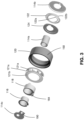
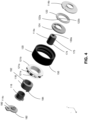
Figures 3 and4 are exploded perspective views of the tensioner shown inFigure 1 ; -
Figure 5 is a sectional side view of the tensioner shown inFigure 1 ; -
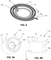
Figure 6 is a sectional side view of a spring that may be included in the tensioner shown inFigure 1 ; -
Figure 7 is a perspective view of the spring shown inFigure 6 ; -
Figure 8 is a spring of the prior art; -
Figure 9A is a perspective view of a shaft from a shaft-and-base unit that is part of the tensioner shown inFigure 1 ; -
Figure 9B is a sectional side view of the shaft shown inFigure 9A ; -
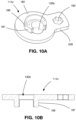
Figure 10A is a perspective view of a shaft cover from the shaft-and-base unit that is part of the tensioner shown inFigure 1 ; -
Figure 10B is a sectional side view of the shaft cover shown inFigure 10A ; -
Figure 11 is a perspective view of a tensioner arm from the tensioner shown inFigure 1 ; -
Figure 12 is a perspective view of a damping carrier from the tensioner shown inFigure 1 ; -
Figure 13 is a plan view of the damping carrier shown inFigure 12 and an alternative tensioner spring to the tensioner spring shown inFigure 6 ; and -
Figures 14-16 are plan views of a tensioner spring that may be used in the tensioner expanding radially during operation under increasing tension in an endless drive member -
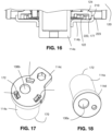
Figure 17 is a perspective view of a shaft and shaft cover; -
Figure 18 is a perspective view of a shaft and a second cover; -
Figures 19A-19C illustrate a method of staking the shaft cover shown inFigure 17 to the shaft shown inFigure 17 . - A
tensioner 100 in accordance with an embodiment of the present disclosure is shown inFigures 1 , and includes one or more features that reduce its overall height as compared to not including any of these features, and that improve its manufacture. Thetensioner 100 may be configured to maintain tension in anendless drive member 103 on anengine 101. Theendless drive member 103 in the example shown inFigure 1 is a timing belt, however, theendless drive member 103 may be any other suitable synchronous endless drive member that transfers rotational power from acrankshaft 104 of theengine 101 to one or more driven components such as, for example, a pair ofcamshafts endless drive member 103 may be referred to as thebelt 103 or as thetiming belt 103, however it will be understood that any suitable endless drive member could be used. -
Figure 2 is a magnified perspective view of thetensioner 100 itself.Figures 3 and4 are exploded perspective views of thetensioner 100.Figure 5 is a sectional elevation view of thetensioner 100. - An overview of the components that are included in the
tensioner 100 are described below. After the overview is provided, selected features will be described in more detail. With reference toFigures 2-5 , thetensioner 100 includes a shaft-and-base unit 114, abushing 116, atensioner arm 118, apulley 120 that rotates on thetensioner arm 118, atensioner spring 122, and a dampingcarrier 124. - The shaft-and-
base unit 114 may include ashaft 114a, abase 114b and ashaft cover 114c that are separate from one another but which are integrally connected by any suitable means, such as, for example, by staking, described further below. The shaft-and-base unit 114 is mountable to be stationary relative to theengine 101 by any suitable means. For example, the shaft-and-base unit 114 may be mountable directly to the engine block as shown inFigure 1 via a threadedfastener 119, which may be, for example, a bolt that passes through afastener aperture 130 in the shaft-and-base unit 114 into the block of theengine 101. Thefastener aperture 130 may be formed by a proximalfastener aperture portion 130a in theshaft 114a (Figure 6 ) and a distalfastener aperture portion 130b in theshaft cover 114c. Theshaft 114a (and the shaft-and-base unit 114 as a whole) further includes a central shaft axis As. It can be seen inFigure 5 that thefastener aperture 130 itself extends along a fastener aperture axis Af that is offset from the central shaft axis As. The offset permits the position of the shaft-and-base unit 114 to be adjusted during mounting of thetensioner 100 on the engine 101 (by pivoting the shaft-and-base unit 114 towards or away from thebelt 103, so as to control its proximity to the belt 103). - Reference is made to
Figures 9A and 9B , which show theshaft 114a from the shaft-and-base unit 114. In the embodiment shown, theshaft 114a has a firstaxial shaft end 170 and a secondaxial shaft end 172 and has a radiallyouter surface 174 that is entirely free of any projections. In other words, the radiallyouter surface 174 is free of any shoulders or the like. The radiallyouter surface 174 includes the arm support surface shown at 175, which is the portion of the radiallyouter surface 174 that supports thetensioner arm 118. As a result, thesurface 174 can be provided with a suitable surface finish for engagement with thebushing 116 via a process where it passes between rollers, as opposed to a shaft-and-base unit of the prior art which has to be set up in a chuck on a machine in order to provide it with a suitable surface finish. The surface finish is helpful in ensuring that thesurface 174 is impregnated with a suitable amount of polymer from the bushing so that there is good sliding contact between thesurface 174 and thebushing 116. - In the embodiment shown, the
shaft 114a includes anarm support portion 176 that is cylindrical and which has thearm support surface 175 thereon, and ashaft bottom 178 at the firstaxial shaft end 170. Theshaft bottom 178 has the proximalfastener aperture portion 130a. Theshaft 114a is open at the secondaxial shaft end 172. Theshaft cover 114c (shown inFigure 10 ) covers the secondaxial shaft end 172 and includes a flange 180 and the distalfastener aperture portion 130b. Theshaft cover 114c is movable on the secondaxial shaft end 172 to a position in which the distalfastener aperture portion 130b is aligned with the proximalfastener aperture portion 130a to form thefastener aperture 130. - The
shaft cover 114c includes anaxial projection 186 having a radially outer locatingsurface 187 thereon that engages a radiallyinner surface 188 of theshaft 114a at the open secondaxial shaft end 172. - The
shaft cover 114c includes atool receiving region 190 that receives a tool to permit a user to adjust the position of the shaft-and-base unit 114 relative to theengine 101, or in some embodiments that permit a user to adjust the position of theshaft cover 114c relative to theshaft 114a. - The flange 180 axially holds the
tensioner arm 118 on theshaft 114a, and may thus be referred to as an arm retaining portion 180. It can be seen that, by having theshaft cover 114c be located using theinner surface 188 of theshaft 114a instead of the outer surface, the overall height of thetensioner 100 can be kept low. By contrast, if theshaft cover 114c was located using the radiallyouter surface 174 of theshaft 114a, theshaft cover 114c would necessarily have to include a portion that extends axially towards the firstaxial shaft end 170 in order to have some axial overlap with the radiallyouter surface 174 of theshaft 114a. This would impinge on thetensioner arm 118 itself if thearm 118 extend as close as it does to the secondaxial shaft end 172 in the example shown in the figures. Accordingly, to provide some clearance, theshaft 114a would have to be taller, which would increase the overall height of the tensioner. By contrast, by locating theshaft cover 114c on the radiallyinner surface 188 of theshaft 114a, the flange 180 itself retains thearm 118 and theshaft 114a can be kept shorter. - The
tensioner arm 118 is pivotally mounted to theshaft 114a (or more generally, to the shaft-and-base unit 114) for pivotal movement about a arm pivot axis, which is the central shaft axis As. Pivotal movement in a first direction D1 (Figure 1 ) may be referred to as movement in a free arm direction. Pivotal movement in a second direction D2 (Figure 1 ) may be referred to as movement in a load stop direction. - Referring to
Figure 11 , thetensioner arm 118 has a firstaxial arm end 196 and a secondaxial arm end 198, and further includes a radiallyouter surface 200 that includes apulley support surface 202, and which extends from the firstaxial arm end 196 to the secondaxial arm end 198 and is entirely free of any radial projections. Thetensioner arm 118 further includes a radiallyinner surface 203 that defines an arm pivot axis As. - The second
axial arm end 198 is on anaxial projection 199 having a firstcircumferential side 201 that is a free arm stop engagement surface. Theshaft cover 114c has a free arm stop 207 thereon. Movement of thetensioner arm 118 in the first direction D1 (Figure 1 ) brings the free arm stop engagement surface towards the free arm stop. - The
bushing 116 is present between the radiallyinner surface 203 of thetensioner arm 118 and thearm support surface 175, and facilitates pivoting movement of thetensioner arm 118 on the shaft-and-base unit 114. Thebushing 116 may be made from any suitable material such as Stanyl TW371 (which is a material based on Nylon PA46) and which is provided by DSM Engineering Plastics B.V. - The
pulley 120 is rotatably mounted to the tensioner arm 118 (e.g. via abearing 121 or any other suitable means) for rotation about a pulley axis Ap that is offset from the arm pivot axis As by a selected offset distance that smaller than a radius of thepulley 120 at the endless drive member engagement surface 150 (shown at Rp). Thepulley 120 has an endless drivemember engagement surface 150 that is engageable with theendless drive member 103. Thepulley 120 is just one example of an endless drive member engagement member that is mountable to thetensioner arm 118 and is engageable with theendless drive member 103. - The
bearing 121 may be provided by a plurality of rollingelements 121a (e.g. balls) and inner andouter races inner race 121b may be a separate element as is commonly provided on bearings, however theouter race 121c may be directly formed in the radially inner surface of thepulley 120. This reduces the number of parts that have to be manufactured. - Reference is made to
Figures 17, 18 ,19A and 19B , which show an alternative embodiment of theshaft 114a. In this alternative embodiment, theshaft 114a is staked to the shaft cover shown at 114c. As can be seen, theshaft 114a has acylindrical body 240 with no axial projections. Theshaft cover 114c has a plurality of stakingapertures 242 about the perimeter of theshaft 114a, which expose the secondaxial shaft end 172. Theshaft cover 114c further includes a staking shoulder 244 that is positioned proximate to, but spaced from the second (distal) end 172 towards the first (proximal)end 170. To assemble theshaft cover 114c onto theshaft 114a, theshaft cover 114c is placed on the second (distal) end 172 of theshaft 114a. Stakingprojections 250 are inserted into the stakingapertures 242 into engagement with thesecond end 172 of theshaft 114a. The stakingprojections 250 deform thesecond end 172 such that thesecond end 172 projects radially outwards onto the staking shoulder 244, thereby locking theshaft cover 114c in place. - In some embodiments, the
shaft cover 114c (Figure 20) has a stakingshoulder 254 that is radially inside of thecylindrical body 240 of theshaft 114a, and the stakingprojections 250 deform the second 172 such that thesecond end 172 projects radially inwardly onto the staking shoulder 244. Therefore, the stakingprojections 250 may, more broadly, be said to deform thesecond end 172 such that thesecond end 172 projects radially onto the staking shoulder 244. - A
bottom cover 114d is shown on theshaft 114a, instead of providing a unitary member that includes the bottom. Thebottom cover 114d includes theaperture portion 130a. - The
tensioner spring 122 is positioned to urge thetensioner arm 118 rotationally to urge thetensioner arm 118 in the first rotational direction (i.e. the free arm direction), thereby driving thepulley 120 into thetiming belt 103, while thebelt 103 applies a force on thepulley 120 urging thetensioner arm 118 in the load stop direction, against the urging of thespring 122. - As shown in
Figures 3-5 , thetensioner spring 122 may be a helical torsion spring, which has afirst end 122a and asecond end 122b. Thespring 122 may include a plurality ofcoils 123, wherein a coil is a segment of thespring 122 that extends through 360 degrees. In the present example, with reference to Figure 8B, thespring 122 has about three coils. The shaft-and-base unit 114 is positioned to receive torque from thefirst spring end 122a, and thetensioner arm 118 is positioned to receive torque from thesecond spring end 122b. - During manufacture of a tensioner, it is preferable for such manufacture to be automated (i.e. accomplished by machines, as opposed to assembly workers) in order to reduce the labour to produce the tensioner. However, in tensioners of the prior art, it has been difficult for a machine to be able to grab a tensioner spring from a bin of such springs for insertion into the tensioner, because the springs had a tendency to tangle with one another while in a bin. As a result, an assembly worker was sometimes used to manually grab springs from a bin, untangle them as necessary and subsequently insert them into the tensioner, thereby slowing down production and increasing the cost of production of the tensioner.
- With reference to
Figure 6 , which shows a sectional view of thetensioner spring 122, in some embodiments, a space to enter between any two adjacent ones of the plurality ofcoils 123 of the tensioner spring is less than a width of each of the plurality ofcoils 123, so as to inhibit the tensioner spring from entangling with anotheridentical tensioner spring 122. The space to enter between any twoadjacent coils 123 is shown at S. The width of thecoils 123 of thespring 122 is shown at Wc. As can be seen, the space S is less than the width Wc. It will be understood that the space S is not the same as the gap between thecoils 123. The gap between thecoils 123 is the distance between the points onadjacent coils 123 that are closest to one another. For thespring 122 shown inFigure 6 , the gap is shown at G. While it is helpful for the gap G to be less than the width of a coil, there is still a tendency for coils on one spring to wedge a pair of adjacent coils apart on a nearby spring if the springs are pushed towards one another, depending on the shape of the coils. If there is a lot of 'lead-in' to the shape of the coils, the gap G may be small, but the space S may be significantly larger, and this may facilitate the wedging apart of adjacent coils. - Based on the above, it has been found that it is more helpful to inhibit entanglement between springs by forming the springs such that the space S is less than the width Wc of the coils, as is exemplified with the springs 122 (shown individually at 122' and 122") shown in
Figure 6 . InFigure 6 , the space S that is identified is the largest space S that exists for the spring 122'. In other words, it is the worst-case scenario. The width Wc that is shown is the width of thecoil 123 of thespring 122" that is nearest the space S in the spring 122'. The width of thecoils 123 of thesprings 122' and 122" may be generally constant, or it may vary along the length of thespring 122. - It will be noted that there are other optional features of the
spring 122 that assist in inhibiting entanglement withadjacent springs 122. For example, it can be seen that thespring 122 is made from a wire having a generally rectangular cross-sectional shape. As a result, the size of the space S is relatively closer to the size of the gap G betweenadjacent coils 123 than it would be for a spring made from wire having a circular cross-sectional shape. - Another optional feature is that the plurality of
coils 123 are arranged generally helically about a longitudinal axis (shown at Aspr) and generally increase in distance away from the axis Aspr in a longitudinal direction. In other words, thespring 122 has a generally conical shape. It will be noted that this conical shape itself reduces the likelihood of entanglement as the gap G and space S are generally in the radial direction, and therefore penetration of the gap G or space S is by a vertical force acting on thesprings 122' and 122". However, it will be noted that the shape of thecoils 123 of thesprings 122' and 122" is generally helical (as shown inFigure 7 ). Thus, the arcs of thecoils 123 inhibit penetration bycoils 123 of the adjacent spring which arc in the opposite direction. The same is not true for springs that have a generally cylindrical shape as opposed to the generally conical shape shown in the figures. - Worded another way, the
tensioner arm 118 is positioned to move in the second direction D2 that is opposite to the first direction D1 during an increase in tension in theendless drive member 103, and thetensioner spring 122 is positioned to expand radially away from the longitudinal axis Aspr or As in response to movement of thetensioner arm 118 in the second direction D2. - Another optional feature that helps to prevent entanglement between
adjacent springs 122 is that, in some embodiments, thetensioner spring 122 is free of tangs, as can be seen inFigure 7 . Thespring 122 is what is sometimes referred to as an 'opening' spring, in the sense that itsends base unit 114 and oftensioner arm 118 and that flexure of thespring 122 during movement of thetensioner arm 118 in the load stop direction causes thecoils 123 of thespring 122 to open up radially. This is in contrast to a closing spring, which is commonly used in some tensioners of the prior art and which requires the ends of the spring to have tangs which hook into corresponding slots in the tensioner arm and shaft-and-base unit, and in which flexure of the spring during movement of thetensioner arm 118 in the load stop direction causes the coils of the spring to constrict radially. - When a spring is formed with tangs, there are natural radii to the bends in the wire of the spring where the tangs begin. An example of such a spring is shown at 160 in
Figure 8 . Thespring 160 has a plurality ofcoils 161 and first and second ends on which there are tangs shown at 162. The radii of the bends in the spring wire at the start of thetangs 162 provides a space S that is relatively large and thereby prone to penetration by a coil from an adjacent spring. - All of these aforementioned features of the
spring 122 assist in inhibiting entanglement of thespring 122 withadjacent springs 122. As a result, thespring 122 can more easily be picked up from a bin by a machine (e.g. an assembly robot) and inserted into a tensioner, to help automate the assembly of the tensioner. In testing of thespring 122 is was found that had about a 1% entanglement rate, whereas other springs of the prior art have been found to have a rate of entanglement of over 80%. - The damping carrier 124 (
Figures 12 and13 ) holds thetensioner spring 122 and provides some of the damping that is present in the tensioner 100 (while other damping is provided by frictional engagement between thetensioner arm 122 and the bushing 116). In the present example, the dampingcarrier 124 includes a springend engagement slot 204 that is positioned to hold thesecond spring end 122b. As a result, thesecond spring end 122b transfers torque to thetensioner arm 118 through awall 205 of the dampingcarrier 124. Thewall 205 engages an arm torque transfer surface 206 (Figure 13 ) on thetensioner arm 118. The armtorque transfer surface 206 may be provided on anaxial projection 208 on thetensioner arm 118. - In order to provide damping, the damping
carrier 124 includes a dampingsurface 210 thereon. In the example shown, the dampingsurface 210 is provided on a radially inner surface 211 of the dampingcarrier 124. In the example shown, the dampingsurface 210 is provided on anaxial projection 212 and has an angular width of about 120 degrees, although other angular widths may be used such as an angular width that is greater than 120 degrees. During torque transfer between thetensioner spring 122 and the tensioner arm 118 (shown inFigure 13 ), a force F is applied by the tensioner arm 118 (specifically from thetorque transfer surface 206 on the axial projection 208) into the assembly of thespring 122 and the dampingcarrier 124. The direction of the force F may be generally tangential to thespring 122 at thesecond spring end 122b. The force F results in a certain force that is transmitted from thefirst spring end 122a into thebase 114b. This force transmitted into the base 114b results in a reaction force shown at F3 transmitted from the base 114b into thefirst spring end 122a. - Based on the positions and orientations of the forces F and F3 (and therefore the positions of the first and
second ends carrier 124 is caused to pivot about the carrier torque receiving surface shown at 209, which engages with thetorque transfer surface 206 on thetensioner arm 118. This pivoting of the dampingcarrier 124 brings the dampingsurface 210 into engagement with the portion of theouter surface 174 of theshaft 114a, thereby causing damping to occur between the dampingcarrier 124 and theshaft 114a. This portion of theouter surface 174 may be referred to as a damping surface 177. The dampingsurface 210 may be referred to as a first dampingsurface 210 and the damping surface 177 may be referred to as a second damping surface, which, in the present embodiment is on theshaft 114a. - However, in an alternative embodiment, the first damping
surface 210 is provided on a radially outer surface of the dampingcarrier 124, and the second damping surface 177 is provided on a radially inner surface of the shaft-and-base unit 114 (e.g. as part of a radially inner surface 222 (Figure 16 ) of anouter lip 223 of the base 114b). In such an alternative embodiment, the dampingcarrier 124, thetensioner spring 122, and thetensioner arm 118 may be arranged such that the pivoting of the dampingcarrier 124 drives the radially outer, first dampingsurface 210 against the radially inner, second damping surface 177, as shown inFigure 16 . - In another alternative embodiment, the damping
carrier 124 may be provided at thefirst end 122a of thetensioner spring 122 instead of thesecond end 122b. In such an embodiment, the first dampingsurface 210 may be provided on either a radially inner or a radially outer surface of the dampingcarrier 124, while the second damping surface 177 is provided on a complementary surface of thetensioner arm 118. - Based on the above, it may be said that the damping
carrier 124 includes a spring end engagement slot (i.e. spring end engagement slot 204) that holds one of the first and second spring ends (122a, 122b). The dampingcarrier 124 further includes a first dampingsurface 210 thereon, wherein thefirst spring end 122a, thesecond spring end 122b, and the first dampingsurface 210 are positioned relative to each other such that the dampingcarrier 124 pivots during force transmission between thetensioner arm 118 and the shaft-and-base unit 114 through thetensioner spring 122 so as to drive the first dampingsurface 210 into a complementary second damping surface 177 on whichever of thetensioner arm 118 and the shaft-and-base unit 114 receives torque from the other of the first and second spring ends 122a, 122b. - As can be seen in
Figure 13 , thesecond spring end 122b and the radially inner damping surface are oriented relative to one another such that a tangential force (e.g. the purely tangential force F, or alternatively a tangential force that is a vector component of a non-tangential force) from thetensioner arm 118 on thetensioner spring 122 at thesecond spring end 122b results in a reaction force F2 by the shaft-and-base unit 114 on the radially inner dampingsurface 210, resulting in frictional damping during movement of thetensioner arm 118 relative to the shaft-and-base unit 114 about the arm pivot axis As. The force F2 shown inFigure 13 is shown as a point force, however, the actual force F2 is a distributed force distributed over some or all of the angular width of the radially inner dampingsurface 210. The point force F2 shown inFigure 13 is a mathematical representation that is the equivalent to that distributed force. A force F3 will be applied on thetensioner spring 122 by a drive surface 212 (Figure 4 ) on the shaft-and-base unit 114 (e.g. on an edge surface of alip 223 on the base 114b) which engages thefirst end 122a of thetensioner spring 122. The force F3 (Figure 13 ) may be tangential to thetensioner spring 122 at thefirst end 122a. -
Figures 14 ,15 and16 illustrate another aspect of the operation of thetensioner spring 122. More particularly, it can be seen that thecoils 123 of thetensioner spring 122 are arranged about the longitudinal axis Aspr such that thecoils 123 are radially offset from one another but axially overlap one another; In other words, thecoils 123 of thespring 122 may be considered to have a generally spiral arrangement, even when there is some axial offset fromcoil 123 tocoil 123. As noted above, the plurality ofcoils 123 includes a radially outermost coil 123o and at least one inner coil 123i. In the example shown inFigure 14 , there is the outer coil 123o, and there are 1.5 inner coils 123i. One of thetensioner arm 118 and the shaft-and-base unit 114 has aspring limit surface 222 thereon (e.g. on the lip 223). In the present example, as can be seen inFigure 5 , thespring limit surface 222 is shown as being a radially inner surface of thebase 114b. - When a relatively low tension is present in the endless drive member 103 (
Figure 1 ), thecoils 123 may be spaced from one another and the outer coils may be spaced from thespring limit surface 222, as can be seen inFigures 5 and14 . - As tension increases in the endless drive member 103 (
Figure 1 ), thetensioner spring 122 progressively locks up by progressive expansion of thecoils 123 into engagement with one another and progressive expansion of the radially outermost coil 123o into engagement with thespring limit surface 222. In the embodiment shown, the outermost coil 123o expands into engagement with thespring limit surface 222, the next innermost coil (shown at 123i1) radially expands into engagement with the outermost coil 123o, and the next innermost coil (which is a partial coil shown at 123i2) expands radially into engagement with the coil 123i1, as shown inFigure 16 . The position shown inFigure 16 may be referred to as the load stop position.Figure 15 shows an intermediate state in which the outermost coil 123o expanded into engagement with thespring limit surface 222. - As a result of the progressive engagement of the
coils 123 with each other and with thespring limit surface 222, the spring rate of thetensioner spring 122 increases progressively. Once all of thecoils 123 are engaged with one another and with thelimit surface 222, thespring 122 provides a solid connection between thetensioner arm 118 and the shaft-and-base unit 114 (i.e. thespring 122 has effectively an infinite spring rate). It will be noted that this is an improvement over a tensioner in which the spring is a helical coil spring (i.e. with a generally cylindrical overall shape). If such a tensioner employed a limit surface, the spring would increase its spring rate rapidly as the spring engaged the limit surface until the spring fully engaged the limit surface and provided a solid connection. This rapid increase in spring rate to infinity could potentially result in shock loading and eventually to failure of some components of the tensioner. - Another feature that will be noted in the
tensioner 100, is that, in some embodiments, such as the embodiment shown in the figures, thetensioner spring 122 acts as a load stop for thetensioner 100, in the sense that thespring 122 itself acts to limit travel of thetensioner arm 118 in the load stop direction, since, as noted above, once thetensioner arm 118 has traveled sufficiently, all of thecoils 123 of thespring 122 are engaged with one another and with thelimit surface 222, such that thespring 122 provides a solid connection between thetensioner arm 118 and the shaft-and-base unit 114, which itself is fixedly connected to a stationary structure such as the engine block, during use. Worded another way, when the tension increases in theendless drive member 103 to a selected tension, radial expansion of the plurality ofcoils 123 is prevented by engagement of the plurality ofcoils 123 with at least thespring limit surface 222. In the present embodiment, when the tension increases in theendless drive member 103 to the selected tension, radial expansion of the plurality ofcoils 123 is prevented by engagement of the plurality ofcoils 123 with each other and with thespring limit surface 222. - While it was disclosed for the
spring limit surface 222 to be a radially inner surface of thebase 114b, it will be understood that thespring limit surface 222 could alternatively be any other surface such as a radially outer surface of theshaft 114, a radially inner surface of thearm 118 or any other suitable location. - It will be noted that this frictional damping force is proportional to the force (and therefore to the torque) applied by the
tensioner arm 118 on thesecond spring end 122b. This is different than the damping force that is provided by thebushing 116, which is proportional to the radially directed force of thetensioner arm 118 on thebushing 116, which is, in turn, proportional to the hub load on thepulley 120. - The
shaft cover 114c additionally has a shaft marker 182 (Figure 2 ) thereon, which in the example shown, may be a notch in the flange 180. Thetensioner arm 118 has anarm marker 184 thereon at an axial end. Thearm marker 184 and theshaft marker 182 cooperate during installation of thetensioner 100 on theengine 101. More specifically, installation of thetensioner 100 may take place as follows: - The
tensioner 100 is mounted by passing thefastener 119 through thefastener aperture 130, and into an aperture in a member that is stationary relative to theengine 101, such as the engine block. Thefastener 119 is not fully tightened initially. As a result, the shaft-and-base unit 114 can be rotated, while keeping thetensioner arm 122 in a substantially constant position with thepulley 120 engaged with the belt 103 (Figure 1 ), so as to adjust the amount of preload there is in thetensioner spring 122 when theengine 101 is off, which in turn adjusts the amount of tension there is in the belt 103 (Figure 1 ). The shaft-and-base unit 114 is rotated until theshaft marker 182 is aligned with thearm marker 184. Thefastener 119 is then tightened down so as to hold the shaft-and-base unit 114 in that position. Thus, during use, when theengine 101 is off, thearm marker 184 is aligned with theshaft marker 182. - By providing a
separate shaft cover 114c, theshaft 114a is able to be made with thesurface 174 without any projections. By contrast, shaft-and-base units of the prior art typically have a flange portion that is used to hold down the tensioner arm. However, producing theshaft 114a andshaft cover 114c as separate elements which are connected mechanically via the fastener 119 (which is needed in any case to mount thetensioner 100 to the engine 101) is less expensive than producing a single shaft member that has an integral flange. - It will be noted that, in some embodiments, the
pulley 120 has a swept volume V (i.e. an occupied volume) which is generally shaped as a thick disc, and which is shown in side view inFigure 19A . In some embodiments, thetensioner spring 122 is positioned substantially entirely within the swept volume V of thepulley 120, as a result of the spring's generally conical shape and the . - The above-described embodiments are intended to be examples only, and alterations and modifications may be carried out to those embodiments by those of skill in the art.
-
- 1. A tensioner for an endless drive member, comprising:
- a shaft-and-base unit that is mountable to be stationary relative to an engine block;
- a tensioner arm that is pivotable relative to the shaft-and-base unit about a tensioner arm axis;
- a pulley that is rotatably mounted to the tensioner arm for rotation about a pulley axis that is offset from the tensioner arm axis, wherein the pulley is engageable with an endless drive member;
- a tensioner spring that is positioned to urge the tensioner arm in a first direction about the tensioner arm axis, wherein the tensioner spring is a torsion spring having a first spring end and a second spring end and a plurality of coils between the first and second spring ends, wherein the shaft-and-base unit is positioned to receive torque from the first spring end and the tensioner arm is positioned to receive torque from the second spring end; and
- a damping carrier that includes a spring end engagement slot that holds one of the first and second spring ends, wherein the damping carrier further includes a first damping surface thereon, and wherein the first spring end, the second spring end, and the first damping surface are positioned relative to each other such the damping carrier pivots during force transmission between the tensioner arm and the shaft-and-base unit through the tensioner spring so as to drive the first damping surface into a complementary second damping surface on whichever of the tensioner arm and the shaft-and-base unit receives torque from the other of the first and second spring ends.
- 2. A tensioner as claimed in item 1, wherein the first spring end, the second spring end, and the first damping surface are positioned relative to each other such that the moment that causes pivoting of the damping carrier relative to the tensioner arm and the complementary second damping surface is on the shaft-and-base unit.
- 3. A tensioner as claimed in item 1, wherein the first damping surface is a radially inner damping surface of the damping carrier.
- 4. A tensioner as claimed in item 3, wherein the radially inner damping surface is positioned radially inward of at least one of the coils.
- 5. A tensioner as claimed in item 1, further comprising a bushing that is positioned radially between the shaft-and-base unit and the tensioner arm to support the tensioner arm radially on the shaft-and-base unit.
- 6. A tensioner as claimed in item 1, wherein the first and second ends are pushed by the shaft-and-base unit and the tensioner arm respectively during torque transfer therebetween, so as to urge the coils to expand radially.
- 7. A tensioner as claimed in item 1, wherein the first damping surface is circumferentially spaced from both the first and second spring ends.
- 8. A tensioner as claimed in item 1, wherein at least a portion of the first damping surface is circumferentially 90 degrees from the second spring end.
- 9. A tensioner as claimed in item 1, wherein the tensioner spring is a spiral spring such includes a plurality of coils that are offset radially from one another.
- 10. A method of assembling a shaft cover onto a shaft for a tensioner, comprising:
- providing a shaft having a cylindrical body, having a first axial shaft end and a second axial shaft end;
- providing a shaft cover;
- placing the shaft cover on one of the first and second axial shaft ends, wherein the shaft cover has a plurality of staking apertures that expose said one of the first and second axial shaft ends, wherein the shaft cover further includes a staking shoulder that is positioned proximate to, but spaced from said one of the first and second axial shaft ends towards the other of the first and second axial shaft ends;
- inserting staking projections into the staking apertures into engagement with the said one of the first and second axial shaft ends; and
- deforming said one of the first and second axial shaft ends using the staking projections such that said one of the first and second axial shaft ends projects radially onto the staking shoulder, thereby locking the shaft cover to the shaft.
- 11. A method as claimed in item 10, wherein said deforming step includes deforming said one of the first and second axial shaft ends using the staking projections such that said one of the first and second axial shaft ends projects radially outwardly onto the staking shoulder, thereby locking the shaft cover to the shaft.
- 12. A tensioner for an endless drive member, comprising:
- a shaft-and-base unit that is mountable to be stationary relative to an engine block;
- a tensioner arm that is pivotable relative to the shaft-and-base unit about a tensioner arm axis;
- a pulley that is rotatably mounted to the tensioner arm for rotation about a pulley axis that is offset from the tensioner arm axis, wherein the pulley is engageable with an endless drive member, wherein the pulley has a swept volume; and
- a tensioner spring that is positioned to urge the tensioner arm in a first direction about the tensioner arm axis, wherein the tensioner spring is a torsion spring having a first spring end and a second spring end and a plurality of coils between the first and second spring ends, wherein the plurality of coils decrease in diameter from one of the first and second spring ends to the other of the first and second spring ends, wherein one of the first and second spring ends is positioned to transfer torque into the shaft-and-base unit and the other of the first and second spring ends is positioned to transfer torque into the tensioner arm, wherein the tensioner spring is positioned substantially entirely within the swept volume of the pulley.
- 13. A tensioner for an endless drive member, comprising:
- a shaft-and-base unit that is mountable to be stationary relative to an engine, wherein the shaft-and-base unit includes a fastener aperture to permit a fastener to pass through to fixedly connect the shaft-and-base unit to the engine;
- a tensioner arm that is pivotable relative to the shaft-and-base unit about a tensioner arm axis;
- a pulley that is rotatably mounted to the tensioner arm for rotation about a pulley axis that is offset from the tensioner arm axis, wherein the pulley is engageable with an endless drive member;
- a tensioner spring that is positioned to urge the tensioner arm in a first direction relative to the shaft-and-base unit, wherein the tensioner spring includes a plurality of coils that are arranged about a longitudinal axis such that the coils are radially offset from one another but axially overlap one another, wherein the plurality of coils includes a radially outermost coil and at least one inner coil;
- wherein one of the tensioner arm and the shaft-and-base unit has a spring limit surface, and wherein, when the tension increases in the endless drive member to a selected tension, radial expansion of the plurality of coils is prevented by engagement of the plurality of coils with at least the spring limit surface.
- 14. A tensioner as claimed in item 13, wherein, when the tension increases in the endless drive member to the selected tension, radial expansion of the plurality of coils is prevented by engagement of the plurality of coils with each other and with the spring limit surface.
- 15. A tensioner for an endless drive member, comprising:
- a shaft-and-base unit that is mountable to be stationary relative to an engine, wherein the shaft-and-base unit includes a fastener aperture to permit a fastener to pass through to fixedly connect the shaft-and-base unit to the engine;
- a tensioner arm that is pivotable relative to the shaft-and-base unit about a tensioner arm axis;
- a pulley that is rotatably mounted to the tensioner arm for rotation about a pulley axis that is offset from the tensioner arm axis, wherein the pulley is engageable with an endless drive member;
- a tensioner spring that is positioned to urge the tensioner arm in a first direction relative to the shaft-and-base unit, wherein the tensioner spring includes a plurality of coils that are arranged about a longitudinal axis such that the coils are radially offset from one another but axially overlap one another, wherein the plurality of coils includes a radially outermost coil and at least one inner coil;
- wherein one of the tensioner arm and the shaft-and-base unit has a spring limit surface, and wherein, as tension increases in the endless drive member, the tensioner spring progressively locks up by progressive expansion of the coils into engagement with one another and progressive expansion of the radially outermost coil into engagement with the spring limit surface.
- 16. A tensioner for an endless drive member, comprising:
- a shaft-and-base unit that is mountable to be stationary relative to an engine, wherein the shaft-and-base unit includes a fastener aperture to permit a fastener to pass through to fixedly connect the shaft-and-base unit to the engine, and wherein the shaft-and-base unit includes a base and a shaft that is separate from the base and has the base mounted thereon, wherein the shaft has a shaft axis and has a first axial shaft end and a second axial shaft end, wherein the shaft has a radially outer surface that includes an arm support surface and which extends from the first axial shaft end to the second axial shaft end and is entirely free of any radial projections;
- a tensioner arm that is pivotably supported on the arm support surface of the shaft for pivoting movement about a tensioner arm axis;
- a pulley that is rotatably mounted to the tensioner arm for rotation about a pulley axis that is offset from the tensioner arm axis, wherein the pulley is engageable with an endless drive member; and
- a tensioner spring that is positioned to urge the tensioner arm in a first direction relative to the shaft-and-base unit, wherein the tensioner spring has a first end, a second end and a plurality of coils between the first and second ends, wherein the first end is positioned to transfer torque with the base and the second end is positioned to transfer torque with the tensioner arm.
- 17. A tensioner as claimed in item 16, wherein the tensioner arm is pivotably supported on the radially outer surface of the shaft via a bushing that is directly supported on the radially outer surface of the shaft.
- 18. A tensioner as claimed in item 16, wherein the shaft includes an arm support portion that is cylindrical and which has the arm support surface thereon, and a shaft bottom at the first axial shaft end, wherein the shaft bottom has a proximal fastener aperture portion, and wherein the shaft is open at the second axial shaft end, wherein the shaft-and-base unit further includes a shaft cover that covers the second axial shaft end and includes an arm retaining portion that axially holds the tensioner arm on the shaft and that includes a distal fastener aperture portion and is movable on the second axial shaft end of the shaft to a position in which the distal fastener aperture portion is aligned with the proximal fastener aperture portion to form the fastener aperture, wherein the shaft has a radially inner locating surface at the second axial shaft end and wherein the shaft cover has a radially outer locating surface that engages the radially inner locating surface on the shaft to locate the distal fastener aperture portion relative to the proximal fastener aperture portion.
- 19. A tensioner as claimed in item 16, wherein the shaft cover has a free arm stop thereon, and wherein the second axial arm end is on an axial projection having a first circumferential side that is a free arm stop engagement surface, wherein movement of the tensioner arm in the first direction brings the free arm stop engagement surface towards the free arm stop.
- 20. A tensioner as claimed in item 19, wherein the tensioner arm has an arm marker thereon at the second axial arm end, and wherein the shaft cover has a shaft marker thereon, wherein, during use, when the engine is off, the arm marker is aligned with the shaft marker.
- 21. A tensioner as claimed in item 16, wherein the pulley is a monolithic member that has a radially inner surface that is a first ball engagement surface, and wherein the tensioner further comprises:
- an inner race that is press-fit on the pulley support surface and which includes a radially outer surface that is a second ball engagement surface; and
- a plurality of balls that rotatably support the pulley on the inner race.
- 22. A tensioner as claimed in item 16, further comprising a damping carrier that includes a spring end engagement slot that is positioned to hold the second spring end, wherein the damping carrier further includes a radially inner damping surface thereon, and wherein the second spring end and the radially inner damping surface are positioned such that a tangential force on the second spring end during said torque transfer moves the damping carrier to bring the radially inner damping surface into frictional engagement or increased frictional engagement with the shaft-and-base unit.
- 23. A tensioner as claimed in item 16, wherein the plurality of coils are spaced from one another by a coil-to-coil gap, and wherein a space to enter between any two adjacent ones of the plurality of coils of the tensioner spring is less than a width of each of the plurality of coils so as to inhibit the tensioner spring from entangling with another identical tensioner spring.
- 24. A tensioner as claimed in item 16, wherein the plurality of coils are arranged generally helically about a longitudinal axis and are spaced radially from one another and generally increase in distance away from the axis in a longitudinal direction.
- 25. A tensioner for an endless drive member, comprising:
- a shaft-and-base unit that is mountable to be stationary relative to an engine, wherein the shaft-and-base unit includes a fastener aperture to permit a fastener to pass through to fixedly connect the shaft-and-base unit to the engine;
- a tensioner arm that is pivotable relative to the shaft-and-base unit about a arm pivot axis, wherein the tensioner arm has a first axial arm end and a second axial arm end, wherein the tensioner arm has a radially outer surface that includes a pulley support surface, and which extends from the first axial arm end to the second axial arm end and is entirely free of any radial projections;
- a pulley that is rotatably supported on the pulley support surface of the tensioner arm for rotation about a pulley axis that is offset from the tensioner arm axis, wherein the pulley is engageable with an endless drive member;
- a bushing that is positioned radially between the shaft-and-base unit and the tensioner arm to support the tensioner arm radially on the shaft-and-base unit; and
- a tensioner spring that is positioned to urge the tensioner arm in a first direction about the tensioner arm axis.
- 26. A tensioner as claimed in item 25, wherein the shaft-and-base unit includes a base and a shaft that is separate from the base and has the base mounted thereon, wherein the shaft has a shaft axis and has a first axial shaft end and a second axial shaft end, wherein the shaft has a radially outer surface that includes an arm support surface and which extends from the first axial shaft end to the second axial shaft end and is entirely free of any radial projections,
and wherein the tensioner spring has a first end, a second end and a plurality of coils between the first and second ends, wherein the first end is positioned to transfer torque with the base and the second end is positioned to transfer torque with the tensioner arm. - 27. A tensioner as claimed in item 26, wherein the tensioner arm is pivotably supported on the shaft via a bushing that is directly supported on the arm support surface.
- 28. A tensioner as claimed in item 26, wherein the shaft includes an arm support portion that is cylindrical and which has the arm support surface thereon, and a shaft bottom at the first axial shaft end, wherein the shaft bottom has a proximal fastener aperture portion, and wherein the shaft is open at the second axial shaft end, wherein the shaft-and-base unit further includes a shaft cover that covers the second axial shaft end and includes an arm retaining portion that axially holds the tensioner arm on the shaft and that includes a distal fastener aperture portion and is movable on the second axial shaft end of the shaft to a position in which the distal fastener aperture portion is aligned with the proximal fastener aperture portion to form the fastener aperture, wherein the shaft has a radially inner locating surface at the second axial shaft end and wherein the shaft cover has a radially outer locating surface that engages the radially inner locating surface on the shaft to locate the distal fastener aperture portion relative to the proximal fastener aperture portion.
- 29. A tensioner as claimed in item 28, wherein the shaft cover has a free arm stop thereon, and wherein the second axial arm end is on an axial projection having a first circumferential side that is a free arm stop engagement surface, wherein movement of the tensioner arm in the first direction brings the free arm stop engagement surface towards the free arm stop.
- 30. A tensioner as claimed in item 28, wherein the tensioner arm has an arm marker thereon at the second axial arm end, and wherein the shaft cover has a shaft marker thereon, wherein, during use, when the engine is off, the arm marker is aligned with the shaft marker.
- 31. A tensioner as claimed in item 25, wherein the pulley is a monolithic member that has a radially inner surface that is a first ball engagement surface, and wherein the tensioner further comprises:
- an inner race that is press-fit on the pulley support surface and which includes a radially outer surface that is a second ball engagement surface; and
- a plurality of balls that rotatably support the pulley on the inner race.
- 32. A tensioner as claimed in item 25, further comprising a damping carrier that includes a spring end engagement slot that is positioned to hold the second spring end, wherein the damping carrier further includes a radially inner damping surface thereon, and wherein the second spring end and the radially inner damping surface are oriented relative to one another such that a tangential force from the tensioner arm on the tensioner spring at the second spring end results in a reaction force of the shaft-and-base unit on the radially inner damping surface, resulting in frictional damping during movement of the tensioner arm relative to the shaft-and-base unit about the arm pivot axis.
- 33. A tensioner as claimed in item 25, wherein the plurality of coils are spaced from one another by a coil-to-coil gap, and wherein a space to enter between any two adjacent ones of the plurality of coils of the tensioner spring is less than a width of each of the plurality of coils so as to inhibit the tensioner spring from entangling with another identical tensioner spring.
- 34. A tensioner as claimed in item 25, wherein the plurality of coils are arranged generally helically about a longitudinal axis and are spaced radially from one another and generally increase in distance away from the axis in a longitudinal direction.
- 35. A tensioner for an endless drive member, comprising:
- a shaft-and-base unit that is mountable to be stationary relative to an engine, wherein the shaft-and-base unit includes a fastener aperture to permit a fastener to pass through to fixedly connect the shaft-and-base unit to the engine;
- a tensioner arm that is pivotable relative to the shaft-and-base unit about a tensioner arm axis;
- a pulley having an endless drive member engagement surface that is engageable with an endless drive member, wherein the pulley is rotatably mounted to the tensioner arm for rotation about a pulley axis that is offset from the tensioner arm axis by an offset distance that is smaller than a radius of the pulley at the endless drive member engagement surface; and
- a tensioner spring that is positioned to urge the tensioner arm in a first direction relative to the shaft-and-base unit, wherein the tensioner spring includes a plurality of coils spaced apart from one another by a coil-to-coil gap, and wherein a space to enter between any two adjacent ones of the plurality of coils of the tensioner spring is less than a width of each of the plurality of coils so as to inhibit the tensioner spring from entangling with another identical tensioner spring.
- 36. A tensioner as claimed in item 35, wherein the tensioner spring is made from wire having a generally rectangular cross-sectional shape.
- 37. A tensioner as claimed in item 35, wherein the plurality of coils are arranged generally helically about a longitudinal axis and generally increase in distance away from the axis in a longitudinal direction.
- 38. A tensioner as claimed in item 35, wherein the tensioner spring is free of tangs.
- 39. A tensioner as claimed in item 35, wherein the tensioner arm is positioned to move in a second direction that is opposite to the first direction during an increase in tension in the endless drive member, and wherein the tensioner spring is positioned to expand radially away from the longitudinal axis in response to movement of the tensioner arm in the second direction.
- 40. A tensioner for an endless drive member, comprising:
- a shaft-and-base unit that is mountable to be stationary relative to an engine, wherein the shaft-and-base unit includes a fastener aperture to permit a fastener to pass through to fixedly connect the shaft-and-base unit to the engine;
- a tensioner arm that is pivotable relative to the shaft-and-base unit about a tensioner arm axis;
- a pulley that is rotatably mounted to the tensioner arm for rotation about a pulley axis that is offset from the tensioner arm axis, wherein the pulley is engageable with an endless drive member;
- a tensioner spring that is positioned to urge the tensioner arm in a first direction relative to the shaft-and-base unit, wherein the tensioner spring includes a plurality of coils that are arranged generally helically about a longitudinal axis and are spaced radially from one another and generally increase in distance away from the axis in a longitudinal direction.
Claims (15)
- A tensioner for an endless drive member, comprising:a shaft-and-base unit that is mountable to be stationary relative to an engine block;a tensioner arm that is pivotable relative to the shaft-and-base unit about a tensioner arm axis;a pulley that is rotatably mounted to the tensioner arm for rotation about a pulley axis that is offset from the tensioner arm axis, wherein the pulley is engageable with an endless drive member, wherein the pulley has a swept volume; and a tensioner spring that is positioned to urge the tensioner arm in a first direction about the tensioner arm axis, wherein the tensioner spring is a torsion spring having a first spring end and a second spring end and a plurality of coils between the first and second spring ends, wherein the plurality of coils decrease in diameter from one of the first and second spring ends to the other of the first and second spring ends, wherein one of the first and second spring ends is positioned to transfer torque into the shaft-and-base unit and the other of the first and second spring ends is positioned to transfer torque into the tensioner arm, wherein the tensioner spring is positioned substantially entirely within the swept volume of the pulley.
- A tensioner according to claim 1, wherein the shaft-and-base unit is positioned to receive torque from the first spring end and the tensioner arm is positioned to receive torque from the second spring end; and
a damping carrier that includes a spring end engagement slot that holds one of the first and second spring ends, wherein the damping carrier further includes a first damping surface thereon, and wherein the first spring end, the second spring end, and the first damping surface are positioned relative to each other such the damping carrier pivots during force transmission between the tensioner arm and the shaft-and-base unit through the tensioner spring so as to drive the first damping surface into a complementary second damping surface on whichever of the tensioner arm and the shaft-and-base unit receives torque from the other of the first and second spring ends. - A tensioner as claimed in claim 2, wherein the first spring end, the second spring end, and the first damping surface are positioned relative to each other such that the moment that causes pivoting of the damping carrier relative to the tensioner arm and the complementary second damping surface is on the shaft- and-base unit.
- A tensioner as claimed in claim 2, wherein the first damping surface is a radially inner damping surface of the damping carrier.
- A tensioner as claimed in claim 4, wherein the radially inner damping surface is positioned radially inward of at least one of the coils.
- A tensioner as claimed in any of claims 1 to 5, further comprising a bushing that is positioned radially between the shaft-and-base unit and the tensioner arm to support the tensioner arm radially on the shaft-and-base unit.
- A tensioner as claimed in any of claims 1 to 6, wherein the first and second ends are pushed by the shaft-and-base unit and the tensioner arm respectively during torque transfer therebetween, so as to urge the coils to expand radially.
- A tensioner as claimed in any of claims 2 to 7, wherein the first damping surface is circumferentially spaced from both the first and second spring ends.
- A tensioner as claimed in any of claims 1 to 8, wherein at least a portion of the first damping surface is circumferentially 90 degrees from the second spring end.
- A tensioner as claimed in any of claims 1 to 9 , wherein the tensioner spring is a spiral spring such includes a plurality of coils that are offset radially from one another.
- A tensioner as claimed in claim 1 wherein the plurality of coils of the tensioner spring are arranged about a longitudinal axis such that the coils are radially offset from one another but axially overlap one another, wherein the plurality of coils includes a radially outermost coil and at least one inner coil;
wherein one of the tensioner arm and the shaft-and-base unit has a spring limit surface, and wherein, as tension increases in the endless drive member, the tensioner spring progressively locks up by progressive expansion of the coils into engagement with one another and progressive expansion of the radially outermost coil into engagement with the spring limit surface. - A tensioner as claimed in claim 1, wherein the pulley is a monolithic member that has a radially inner surface that is a first ball engagement surface, and wherein the tensioner further comprises:
an inner race that is press-fit on the pulley support surface and which includes a radially outer surface that is a second ball engagement surface; and a plurality of balls that rotatably support the pulley on the inner race. - A tensioner as claimed in claim 1, wherein the plurality of coils are spaced from one another by a coil-to-coil gap, and wherein a space to enter between any two adjacent ones of the plurality of coils of the tensioner spring is less than a width of each of the plurality of coils so as to inhibit the tensioner spring from entangling with another identical tensioner spring.
- A tensioner as claimed in claim 1, wherein the plurality of coils are arranged generally helically about a longitudinal axis and are spaced radially from one another and generally increase in distance away from the axis in a longitudinal direction.
- A tensioner as claimed in claim 1, wherein the tensioner spring is free of tangs.
Applications Claiming Priority (4)
| Application Number | Priority Date | Filing Date | Title |
|---|---|---|---|
| US201762491469P | 2017-04-28 | 2017-04-28 | |
| US201762568097P | 2017-10-04 | 2017-10-04 | |
| EP18791139.1A EP3615845B1 (en) | 2017-04-28 | 2018-05-01 | Timing belt tensioner with improved construction |
| PCT/CA2018/050508 WO2018195673A1 (en) | 2017-04-28 | 2018-05-01 | Timing belt tensioner with improved construction |
Related Parent Applications (1)
| Application Number | Title | Priority Date | Filing Date |
|---|---|---|---|
| EP18791139.1A Division EP3615845B1 (en) | 2017-04-28 | 2018-05-01 | Timing belt tensioner with improved construction |
Publications (1)
| Publication Number | Publication Date |
|---|---|
| EP4166814A1 true EP4166814A1 (en) | 2023-04-19 |
Family
ID=63918758
Family Applications (2)
| Application Number | Title | Priority Date | Filing Date |
|---|---|---|---|
| EP18791139.1A Active EP3615845B1 (en) | 2017-04-28 | 2018-05-01 | Timing belt tensioner with improved construction |
| EP22213079.1A Pending EP4166814A1 (en) | 2017-04-28 | 2018-05-01 | Timing belt tensioner with improved construction |
Family Applications Before (1)
| Application Number | Title | Priority Date | Filing Date |
|---|---|---|---|
| EP18791139.1A Active EP3615845B1 (en) | 2017-04-28 | 2018-05-01 | Timing belt tensioner with improved construction |
Country Status (6)
| Country | Link |
|---|---|
| US (1) | US11353092B2 (en) |
| EP (2) | EP3615845B1 (en) |
| BR (1) | BR112019022504A2 (en) |
| ES (1) | ES2940109T3 (en) |
| PL (1) | PL3615845T3 (en) |
| WO (1) | WO2018195673A1 (en) |
Citations (3)
| Publication number | Priority date | Publication date | Assignee | Title |
|---|---|---|---|---|
| US5244438A (en) * | 1992-03-27 | 1993-09-14 | Ina Walziager Schaeffler Kg | Tension for belts or chains |
| WO2006137086A1 (en) * | 2005-06-20 | 2006-12-28 | Dayco Europe S.R.L. Con Unico Socio | Asymetric damping belt tensioner |
| US20080176687A1 (en) * | 2007-01-22 | 2008-07-24 | Holger Schever | Tensioner and installation assembly |
Family Cites Families (35)
| Publication number | Priority date | Publication date | Assignee | Title |
|---|---|---|---|---|
| JP2893263B2 (en) * | 1988-04-01 | 1999-05-17 | 三菱自動車工業株式会社 | Auto Tenshiyona |
| US4917655A (en) * | 1989-03-01 | 1990-04-17 | Ina Bearing Co., Inc. | Self adjusting timing belt tensioner |
| US5443424A (en) * | 1994-10-20 | 1995-08-22 | Dayco Products, Inc. | Belt tensioner and method of making the same |
| US5462494A (en) * | 1994-10-20 | 1995-10-31 | Dayco Products, Inc. | Belt tensioner and method of making the same |
| IT1275651B1 (en) * | 1994-10-28 | 1997-10-17 | Dayco Pti Spa | IMPROVEMENTS IN DRIVE BELT TENSIONERS |
| US5919107A (en) * | 1996-08-21 | 1999-07-06 | Litens Automotive Partnership | Belt tensioner for motor vehicle |
| IT1291485B1 (en) * | 1997-01-31 | 1999-01-11 | Dayco Europe Spa | TENSIONER FOR A DRIVE BELT. |
| US6375588B1 (en) * | 1999-04-12 | 2002-04-23 | Litens Automotive Partnership | Tensioner with viscous coupled one way wrap spring anti-kickback clutch |
| US6206797B1 (en) * | 1999-08-13 | 2001-03-27 | Dayco Products, Inc. | Belt tensioner with flexible armplate |
| US6932731B2 (en) * | 2001-07-05 | 2005-08-23 | Ina-Schaeffler Kg | Tensioner |
| JP4293902B2 (en) * | 2001-07-31 | 2009-07-08 | リテンズ オートモーティヴ パートナーシップ | Belt tensioner with mounting pin |
| DE10152364A1 (en) | 2001-10-24 | 2003-05-08 | Ina Schaeffler Kg | jig |
| US6863631B2 (en) * | 2001-12-20 | 2005-03-08 | Dayco Products, Llc | Unidirectional motion asymmetric damped tensioner |
| US6855079B2 (en) * | 2002-09-30 | 2005-02-15 | Fenner, Inc. | Bi-directional belt tensioner |
| WO2004057212A1 (en) | 2002-12-21 | 2004-07-08 | Ina-Schaeffler Kg | Tensioning device for a traction mechanism drive |
| US7637829B2 (en) * | 2004-09-29 | 2009-12-29 | The Gates Corporation | Eccentric pivot arm tensioner |
| EP1838978B1 (en) * | 2005-01-19 | 2009-07-08 | Litens Automotive Partnership | Timing belt tensioner |
| JP5148475B2 (en) * | 2005-03-21 | 2013-02-20 | ライテンズ オートモーティブ パートナーシップ | Tensioner with re-installation feature |
| US20080113835A1 (en) * | 2006-11-09 | 2008-05-15 | Schaeffler Kg | Eccentric tensioning device |
| WO2008068782A1 (en) * | 2006-12-04 | 2008-06-12 | Dayco Europe S.R.L. | Pulley tensioner for a belt drive for use in contact with oil. |
| DE202007005929U1 (en) * | 2006-12-21 | 2007-12-13 | Schaeffler Kg | Locking of an eccentric clamping device |
| US7850560B2 (en) * | 2006-12-21 | 2010-12-14 | Schaeffler Technologies Gmbh & Co. Kg | Double eccentric tensioning device |
| US8641564B2 (en) * | 2007-06-05 | 2014-02-04 | Dayco Europe S.R.L. | Pulley tensioner for an oil wet belt drive |
| US8292765B2 (en) * | 2007-06-05 | 2012-10-23 | Dayco Europe S.R.L. | Pulley tensioner for an oil wet belt drive |
| ES2328207B1 (en) | 2007-12-13 | 2010-09-06 | Timkem Irb, S.A. | INTEGRATED TENSIONER FOR BELTS. |
| US20100069185A1 (en) * | 2008-09-18 | 2010-03-18 | Ward Peter Alan | Tensioner |
| US7951030B2 (en) * | 2008-12-04 | 2011-05-31 | The Gates Corporation | Tensioner |
| DE202010017870U1 (en) * | 2010-09-03 | 2012-11-27 | Schaeffler Technologies AG & Co. KG | Eccentric tensioner |
| US8734279B2 (en) * | 2011-06-08 | 2014-05-27 | Gates Corporation | Tensioner |
| WO2014063228A1 (en) | 2012-10-22 | 2014-05-01 | Litens Automotive Partnership | Tensioner with increased damping |
| US8926462B2 (en) * | 2012-10-24 | 2015-01-06 | The Gates Corporation | Tensioner |
| CN203770558U (en) * | 2014-03-25 | 2014-08-13 | 宁波丰茂远东橡胶有限公司 | High-damping low-attenuation tensioner for engine |
| FR3023891B1 (en) * | 2014-07-18 | 2018-01-05 | Skf Ab | TENSIONING DEVICE OF A TRACTION MEMBER |
| FR3038028B1 (en) * | 2015-06-24 | 2018-11-23 | Aktiebolaget Skf | TENDERING ROLLER DEVICE |
| EP3199834B1 (en) * | 2016-01-29 | 2018-11-07 | Aktiebolaget SKF | Pulley device for a belt, installation method of such a device and motor vehicle equipped with such a device |
-
2018
- 2018-05-01 US US16/605,971 patent/US11353092B2/en active Active
- 2018-05-01 BR BR112019022504-8A patent/BR112019022504A2/en not_active Application Discontinuation
- 2018-05-01 WO PCT/CA2018/050508 patent/WO2018195673A1/en active Application Filing
- 2018-05-01 EP EP18791139.1A patent/EP3615845B1/en active Active
- 2018-05-01 ES ES18791139T patent/ES2940109T3/en active Active
- 2018-05-01 PL PL18791139.1T patent/PL3615845T3/en unknown
- 2018-05-01 EP EP22213079.1A patent/EP4166814A1/en active Pending
Patent Citations (3)
| Publication number | Priority date | Publication date | Assignee | Title |
|---|---|---|---|---|
| US5244438A (en) * | 1992-03-27 | 1993-09-14 | Ina Walziager Schaeffler Kg | Tension for belts or chains |
| WO2006137086A1 (en) * | 2005-06-20 | 2006-12-28 | Dayco Europe S.R.L. Con Unico Socio | Asymetric damping belt tensioner |
| US20080176687A1 (en) * | 2007-01-22 | 2008-07-24 | Holger Schever | Tensioner and installation assembly |
Also Published As
| Publication number | Publication date |
|---|---|
| BR112019022504A2 (en) | 2020-05-12 |
| EP3615845B1 (en) | 2022-12-14 |
| EP3615845A4 (en) | 2020-12-30 |
| US11353092B2 (en) | 2022-06-07 |
| EP3615845A1 (en) | 2020-03-04 |
| ES2940109T3 (en) | 2023-05-03 |
| WO2018195673A9 (en) | 2019-06-06 |
| PL3615845T3 (en) | 2023-04-24 |
| US20210140518A1 (en) | 2021-05-13 |
| WO2018195673A1 (en) | 2018-11-01 |
Similar Documents
| Publication | Publication Date | Title |
|---|---|---|
| EP1844245B1 (en) | Torque limited decoupler | |
| EP1996835B1 (en) | Tensioner for flexible drives | |
| AU675175B2 (en) | Belt tensioner and methods of making same | |
| CN109268461B (en) | Belt tensioner | |
| US20120010034A1 (en) | Traction mechanism drive having a vibration damper | |
| US8439781B2 (en) | Radial damping mechanism and use for belt tensioning | |
| US20100178990A1 (en) | Decoupler with spring travel limiter | |
| JP6796965B2 (en) | Tensioning device | |
| US20120028744A1 (en) | Belt tensioning unit | |
| KR20160010499A (en) | Tensioner with improved damping | |
| US20130225341A1 (en) | Tensioning device for a traction element and method of installation of such a device | |
| US8932163B2 (en) | Belt tensioning device with variable spring factor | |
| EP3615845B1 (en) | Timing belt tensioner with improved construction | |
| CN110546405B (en) | Timing belt tensioner with improved structure | |
| EP0750125B1 (en) | Bearing retainer | |
| US20210025482A1 (en) | Multi-configuration belt tensioner | |
| WO2016070282A1 (en) | Tensioner with progressive stop |
Legal Events
| Date | Code | Title | Description |
|---|---|---|---|
| PUAI | Public reference made under article 153(3) epc to a published international application that has entered the european phase |
Free format text: ORIGINAL CODE: 0009012 |
|
| STAA | Information on the status of an ep patent application or granted ep patent |
Free format text: STATUS: THE APPLICATION HAS BEEN PUBLISHED |
|
| AC | Divisional application: reference to earlier application |
Ref document number: 3615845 Country of ref document: EP Kind code of ref document: P |
|
| AK | Designated contracting states |
Kind code of ref document: A1 Designated state(s): AL AT BE BG CH CY CZ DE DK EE ES FI FR GB GR HR HU IE IS IT LI LT LU LV MC MK MT NL NO PL PT RO RS SE SI SK SM TR |
|
| STAA | Information on the status of an ep patent application or granted ep patent |
Free format text: STATUS: REQUEST FOR EXAMINATION WAS MADE |
|
| 17P | Request for examination filed |
Effective date: 20230703 |
|
| RBV | Designated contracting states (corrected) |
Designated state(s): AL AT BE BG CH CY CZ DE DK EE ES FI FR GB GR HR HU IE IS IT LI LT LU LV MC MK MT NL NO PL PT RO RS SE SI SK SM TR |
|
| STAA | Information on the status of an ep patent application or granted ep patent |
Free format text: STATUS: EXAMINATION IS IN PROGRESS |
|
| 17Q | First examination report despatched |
Effective date: 20240223 |