EP0750125B1 - Bearing retainer - Google Patents
Bearing retainer Download PDFInfo
- Publication number
- EP0750125B1 EP0750125B1 EP96304595A EP96304595A EP0750125B1 EP 0750125 B1 EP0750125 B1 EP 0750125B1 EP 96304595 A EP96304595 A EP 96304595A EP 96304595 A EP96304595 A EP 96304595A EP 0750125 B1 EP0750125 B1 EP 0750125B1
- Authority
- EP
- European Patent Office
- Prior art keywords
- bearing
- retainer
- ring
- separator elements
- rollers
- Prior art date
- Legal status (The legal status is an assumption and is not a legal conclusion. Google has not performed a legal analysis and makes no representation as to the accuracy of the status listed.)
- Expired - Lifetime
Links
Images

Classifications
-
- F—MECHANICAL ENGINEERING; LIGHTING; HEATING; WEAPONS; BLASTING
- F16—ENGINEERING ELEMENTS AND UNITS; GENERAL MEASURES FOR PRODUCING AND MAINTAINING EFFECTIVE FUNCTIONING OF MACHINES OR INSTALLATIONS; THERMAL INSULATION IN GENERAL
- F16C—SHAFTS; FLEXIBLE SHAFTS; ELEMENTS OR CRANKSHAFT MECHANISMS; ROTARY BODIES OTHER THAN GEARING ELEMENTS; BEARINGS
- F16C43/00—Assembling bearings
- F16C43/04—Assembling rolling-contact bearings
- F16C43/06—Placing rolling bodies in cages or bearings
-
- F—MECHANICAL ENGINEERING; LIGHTING; HEATING; WEAPONS; BLASTING
- F16—ENGINEERING ELEMENTS AND UNITS; GENERAL MEASURES FOR PRODUCING AND MAINTAINING EFFECTIVE FUNCTIONING OF MACHINES OR INSTALLATIONS; THERMAL INSULATION IN GENERAL
- F16C—SHAFTS; FLEXIBLE SHAFTS; ELEMENTS OR CRANKSHAFT MECHANISMS; ROTARY BODIES OTHER THAN GEARING ELEMENTS; BEARINGS
- F16C19/00—Bearings with rolling contact, for exclusively rotary movement
- F16C19/22—Bearings with rolling contact, for exclusively rotary movement with bearing rollers essentially of the same size in one or more circular rows, e.g. needle bearings
- F16C19/24—Bearings with rolling contact, for exclusively rotary movement with bearing rollers essentially of the same size in one or more circular rows, e.g. needle bearings for radial load mainly
- F16C19/26—Bearings with rolling contact, for exclusively rotary movement with bearing rollers essentially of the same size in one or more circular rows, e.g. needle bearings for radial load mainly with a single row of rollers
-
- F—MECHANICAL ENGINEERING; LIGHTING; HEATING; WEAPONS; BLASTING
- F16—ENGINEERING ELEMENTS AND UNITS; GENERAL MEASURES FOR PRODUCING AND MAINTAINING EFFECTIVE FUNCTIONING OF MACHINES OR INSTALLATIONS; THERMAL INSULATION IN GENERAL
- F16C—SHAFTS; FLEXIBLE SHAFTS; ELEMENTS OR CRANKSHAFT MECHANISMS; ROTARY BODIES OTHER THAN GEARING ELEMENTS; BEARINGS
- F16C33/00—Parts of bearings; Special methods for making bearings or parts thereof
- F16C33/30—Parts of ball or roller bearings
- F16C33/46—Cages for rollers or needles
- F16C33/4611—Cages for rollers or needles with hybrid structure, i.e. with parts made of distinct materials
-
- F—MECHANICAL ENGINEERING; LIGHTING; HEATING; WEAPONS; BLASTING
- F16—ENGINEERING ELEMENTS AND UNITS; GENERAL MEASURES FOR PRODUCING AND MAINTAINING EFFECTIVE FUNCTIONING OF MACHINES OR INSTALLATIONS; THERMAL INSULATION IN GENERAL
- F16C—SHAFTS; FLEXIBLE SHAFTS; ELEMENTS OR CRANKSHAFT MECHANISMS; ROTARY BODIES OTHER THAN GEARING ELEMENTS; BEARINGS
- F16C33/00—Parts of bearings; Special methods for making bearings or parts thereof
- F16C33/30—Parts of ball or roller bearings
- F16C33/46—Cages for rollers or needles
- F16C33/4617—Massive or moulded cages having cage pockets surrounding the rollers, e.g. machined window cages
- F16C33/4664—Massive or moulded cages having cage pockets surrounding the rollers, e.g. machined window cages with more than three parts, e.g. two end rings connected by individual stays
-
- F—MECHANICAL ENGINEERING; LIGHTING; HEATING; WEAPONS; BLASTING
- F16—ENGINEERING ELEMENTS AND UNITS; GENERAL MEASURES FOR PRODUCING AND MAINTAINING EFFECTIVE FUNCTIONING OF MACHINES OR INSTALLATIONS; THERMAL INSULATION IN GENERAL
- F16C—SHAFTS; FLEXIBLE SHAFTS; ELEMENTS OR CRANKSHAFT MECHANISMS; ROTARY BODIES OTHER THAN GEARING ELEMENTS; BEARINGS
- F16C33/00—Parts of bearings; Special methods for making bearings or parts thereof
- F16C33/30—Parts of ball or roller bearings
- F16C33/46—Cages for rollers or needles
- F16C33/49—Cages for rollers or needles comb-shaped
- F16C33/491—Cages for rollers or needles comb-shaped applied as pairs for retaining both ends of the rollers or needles
-
- F—MECHANICAL ENGINEERING; LIGHTING; HEATING; WEAPONS; BLASTING
- F16—ENGINEERING ELEMENTS AND UNITS; GENERAL MEASURES FOR PRODUCING AND MAINTAINING EFFECTIVE FUNCTIONING OF MACHINES OR INSTALLATIONS; THERMAL INSULATION IN GENERAL
- F16C—SHAFTS; FLEXIBLE SHAFTS; ELEMENTS OR CRANKSHAFT MECHANISMS; ROTARY BODIES OTHER THAN GEARING ELEMENTS; BEARINGS
- F16C2300/00—Application independent of particular apparatuses
- F16C2300/10—Application independent of particular apparatuses related to size
- F16C2300/14—Large applications, e.g. bearings having an inner diameter exceeding 500 mm
Definitions
- This invention relates generally to bearing retainers and, more particularly, to a modular bearing retainer suitable for retaining rollers within large diameter roller bearings, according to the pre-caracterising portion of claim 1 (US 5 352 047).
- bearing retainers that are machines out of large diameter, heavy wall, non-ferrous tubing, resulting in high material and processing costs. Additionally, such bearing retainers need to be unique for any combination of roller diameter, length, pitch and pitch diameter, and must be machined accordingly. In many cases, the resulting machined bearing retainer may restrict lubricant flow and may have a heavy mass that can lead to failure from reversing loads, in particular applications.
- a bearing retainer for use with a roller bearing having rollers between an inner bearing ring and an outer bearing ring
- the bearing retainer comprising an annular retainer ring to be positioned between the inner bearing ring and the outer bearing ring such that the retainer ring engages first ends of the rollers to retain the bearing retainer in the axially inward direction
- a plurality of separator elements characterised in that the separator elements are pivotably mounted on the retainer ring such that the separator elements space the rollers circumferentially, the separator elements including a narrow portion for engagement with a thrust flange of one of the inner and outer bearing rings to restrain the bearing retainer in an axial direction and including a wide portion for engagement with the respective rollers to retain the rollers in one of the radially outward and radially inward directions.
- Figures 1 and 2 illustrate a conventional bearing retainer 10 machined from brass, bronze, ductile iron or steel for use with a roller bearing.
- a retainer body 12 has separator portions 14 forming roller pockets 16.
- a retainer end plate 18 is fixed to the retainer body 12 by recessed rivets 20 (not shown in Figure 1) or by screws or other fasteners through counterbored holes 22 and 24 after insertion of the rollers, not shown.
- Figure 3 illustrates portions of two of the present bearing retainers 26 and 28 with one of a plurality of rollers 30 in position therebetween.
- the bearing retainers 26 and 28 each comprise an annular retainer ring 32 and a plurality of separator elements 34 that space the rollers 30 circumferentially.
- the separator elements 34 are wedge-shaped with a narrow portion 36 for engagement with a thrust flange, as described below, and an opposite wide portion 38 for engagement with the rollers 30 to restrain the rollers in either the radially outward or radially inward direction.
- the wide portion 38 limits radially inward movement of the rollers 30.
- the separator elements 34 are mounted on the retainer ring 32 so as to be axially inward of the retainer ring 32 and pivotally movable with respect to the retainer ring 32. Any convenient type of pivotal mounting may be used.
- the separator elements 34 are mounted by metallic clips 40 and pins 42.
- the metallic clips 40 allow a predetermined amount of pivotal motion but prevent full rotation of the separator elements.
- the pivotable mounting of the separator elements provides flexibility and reduces stress on the retainer ring, allowing a less massive structure to be used.
- Figure 4 illustrates a second embodiment, where separator elements 44 extend the full axial length of rollers 46 and are pivotally mounted on a first retainer ring 48 and a second retainer ring 50.
- a narrow portion 52 of each separator element 44 engages a thrust flange, as described below, and a wide portion 54 engages the rollers 46 to limit radial movement of the rollers.
- the separator elements 44 could be reversed, with the wide portion 54 projecting radially outward, for roller bearings with either a flanged inner or flanged outer race.
- the metallic clip 40 is illustrated in Figure 5 and may be formed as a simple stamping with a barbed end 56 to be insert moulded into a polymer composite or sintered product forming the separator elements 34 and 44.
- a mid-portion 57 extends axially from the separator elements 34 and 44 to engage the retainer ring and limit pivotal motion.
- the metallic clip/separator element subassembly may be attached by a pin 42, rivet, screw or other device, or by fitting a "U" type clip having an integral, formed tab or dimple, to engage a locating hole 58, over the ring and into the insert.
- Figure 6 illustrates the bearing retainer 28 of Figure 3 in position against an outer bearing ring 60 and with the roller 30 in a channel-shaped raceway 62.
- An axially outer thrust flange 64 and an axially inner thrust flange 66 retain the rollers axially.
- the narrow portion 36 (shown in Figure 3) of each separator element 34 engages the outer thrust flange 64 to restrain axially outward movement of the bearing retainer 28.
- the rollers 30 engage the retainer ring 32 and restrain axially inward movement of the bearing retainer 28.
- FIG. 7 illustrates a bearing retainer 70 similar to the embodiments previously described but employing a snap-together assembly.
- the separator elements 72 have stud means 74 engageable with keyhole shaped slots 76 in the radially outward perimeter of the retainer ring 78.
- the separator elements 72 each have a narrow portion 80 extending radially inward for engagement with a thrust flange of an inner bearing ring and have a wide portion 82 extending radially outward to restrain radially outward movement of rollers, not shown.
- Other variations with the narrow and wide portions reversed or with the keyhole shaped slots 72 in the radially inward perimeter of the retainer ring 78 would be used for various roller bearing applications.
- Figure 8 illustrates a preferred construction of stud means 74, where a head portion 84 engages the retainer ring 78 to restrain axially outward movement of the retainer ring, a pin portion 86 penetrates the separator element 72, and a raised shaft portion 88 spaces the head portion 84 from the separator element 72.
- a bushing 90 loosely overlies the shaft portion 88 and is freely rotatable with respect to the shaft portion 88.
- the bushings 90 are resiliently deformable so as to collapse during insertion into the narrow openings of the slots 76 and reform themselves to conform to the slots to enhance the snap-together assembly of the bearing retainer 70.
- the pin 86 may be secured as a rivet or by various other means.
- bearing retainers 70 are illustrated in combination with a roller bearing 92 having an outer bearing ring 94, inner bearing ring 96 and rollers 97.
- the inner bearing ring 96 has a channel-shaped inner raceway with thrust flanges 98 in engagement with the narrow portions 80 of the separator elements 72 to restrain the bearing retainers 70 in the radially outward direction.
- the bearing retainers 70 are piloted by engagement of the thrust flanges 98 by radially inner surfaces of the retainer rings 78, thereby avoiding any wiping of lubricant from the inner raceway.
- the present construction provides a modular assembly constructed from a pool of common components, or components requiring only minor geometry differences accomplished with inexpensive, adaptable tooling.
- Common components can be used for a broad range of roller bearings with various roller sizes, pitch and pitch diameter. Portions of the assembly are designed such that near net shape raw material may be used to achieve the geometry differences through adjustable or adaptive tooling.
- the present bearing retainer is low mass and provides improved space for lubricant with respect to prior art devices.
- the separator elements may be moulded of polymer or may be made from ferrous or non-ferrous metals or other materials by investment casting, machining or other means.
- separator elements extend only a fraction of the roller length, two assemblies for each roller path are preferred, operating independently of each other, and can accommodate any length roller.
- a simple wedge-shaped separator element configuration accommodates various roller diameters and moderate differences in circumferential spacing, adding increased versatility.
- the diameter of the retainer ring would usually change with the pitch diameter of any given roller bearing; however, the material would be the same cross-section. By changing the spacing of the locating holes and the blank length, any desired ring could be formed from a common stock material. Various sequences may be used to facilitate assembly, depending on the type of roller bearing with which the invention is used. At least a portion of the separator elements may be attached to the retainer ring after the retainer ring and rollers are positioned within a channelled raceway.
- the present construction allows several combinations of roller diameters, lengths, pitch and pitch diameter to be accommodated with a standard separator element subassembly and a retainer ring that are easily manufactured.
- Various sized separator elements, each accommodating several combinations of bearing parameters facilitates existing roller bearing configurations and permits satisfying new applications from a pool of standard components.
- the design is light in weight and leaves much of the roller bearing open to free circulation of lubrication.
Landscapes
- Engineering & Computer Science (AREA)
- General Engineering & Computer Science (AREA)
- Mechanical Engineering (AREA)
- Rolling Contact Bearings (AREA)
Description
- This invention relates generally to bearing retainers and, more particularly, to a modular bearing retainer suitable for retaining rollers within large diameter roller bearings, according to the pre-caracterising portion of claim 1 (US 5 352 047).
- In conventional large roller bearings, the rollers are typically retained by bearing retainers that are machines out of large diameter, heavy wall, non-ferrous tubing, resulting in high material and processing costs. Additionally, such bearing retainers need to be unique for any combination of roller diameter, length, pitch and pitch diameter, and must be machined accordingly. In many cases, the resulting machined bearing retainer may restrict lubricant flow and may have a heavy mass that can lead to failure from reversing loads, in particular applications.
- According to the present invention, there is provided a bearing retainer for use with a roller bearing having rollers between an inner bearing ring and an outer bearing ring, the bearing retainer comprising an annular retainer ring to be positioned between the inner bearing ring and the outer bearing ring such that the retainer ring engages first ends of the rollers to retain the bearing retainer in the axially inward direction, and a plurality of separator elements, characterised in that the separator elements are pivotably mounted on the retainer ring such that the separator elements space the rollers circumferentially, the separator elements including a narrow portion for engagement with a thrust flange of one of the inner and outer bearing rings to restrain the bearing retainer in an axial direction and including a wide portion for engagement with the respective rollers to retain the rollers in one of the radially outward and radially inward directions.
- For a better understanding of the invention and to show how the same is carried into effect, reference will now be made, by way of example, to the accompanying drawings, in which:-
- Figure 1 is an exploded cross-sectional view of a conventional bearing retainer according to the prior art;
- Figure 2 is an end view of a portion of the conventional bearing retainer of Figure 1, with portions cut away;
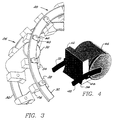
- Figure 3 is a perspective view of portions of two bearing retainers according to the present invention in combination with a roller;
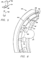
- Figure 4 is a perspective view of a second embodiment of the present bearing retainer,
- Figure 5 is an enlarged pictorial view of a clip and rivet for use in the bearing retainers of Figures 3 and 4;
- Figure 6 is a perspective view of the bearing retainer of Figure 3 in combination with a roller and outer bearing ring;
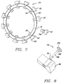
- Figure 7 is an exploded view of a third embodiment of the present bearing retainer;
- Figure 8 is an exploded view of a separator element, stud and bushing for use in the bearing retainer of Figure 7; and
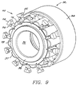
- Figure 9 is an exploded view of two bearing retainers of Figure 7 in combination with a roller bearing.
-
- Figures 1 and 2 illustrate a
conventional bearing retainer 10 machined from brass, bronze, ductile iron or steel for use with a roller bearing. Aretainer body 12 hasseparator portions 14 formingroller pockets 16. A retainer end plate 18 is fixed to theretainer body 12 by recessed rivets 20 (not shown in Figure 1) or by screws or other fasteners throughcounterbored holes 22 and 24 after insertion of the rollers, not shown. - Figure 3 illustrates portions of two of the
present bearing retainers rollers 30 in position therebetween. Thebearing retainers annular retainer ring 32 and a plurality ofseparator elements 34 that space therollers 30 circumferentially. Theseparator elements 34 are wedge-shaped with anarrow portion 36 for engagement with a thrust flange, as described below, and an oppositewide portion 38 for engagement with therollers 30 to restrain the rollers in either the radially outward or radially inward direction. In the embodiment of Figure 3, thewide portion 38 limits radially inward movement of therollers 30. - The
separator elements 34 are mounted on theretainer ring 32 so as to be axially inward of theretainer ring 32 and pivotally movable with respect to theretainer ring 32. Any convenient type of pivotal mounting may be used. In the embodiment of Figure 3, for example, theseparator elements 34 are mounted by metallic clips 40 andpins 42. The metallic clips 40 allow a predetermined amount of pivotal motion but prevent full rotation of the separator elements. The pivotable mounting of the separator elements provides flexibility and reduces stress on the retainer ring, allowing a less massive structure to be used. - Figure 4 illustrates a second embodiment, where separator elements 44 extend the full axial length of
rollers 46 and are pivotally mounted on a first retainer ring 48 and a second retainer ring 50. Anarrow portion 52 of each separator element 44 engages a thrust flange, as described below, and awide portion 54 engages therollers 46 to limit radial movement of the rollers. As with the first embodiment, the separator elements 44 could be reversed, with thewide portion 54 projecting radially outward, for roller bearings with either a flanged inner or flanged outer race. - One form of the metallic clip 40 is illustrated in Figure 5 and may be formed as a simple stamping with a barbed end 56 to be insert moulded into a polymer composite or sintered product forming the
separator elements 34 and 44. A mid-portion 57 extends axially from theseparator elements 34 and 44 to engage the retainer ring and limit pivotal motion. The metallic clip/separator element subassembly may be attached by apin 42, rivet, screw or other device, or by fitting a "U" type clip having an integral, formed tab or dimple, to engage a locating hole 58, over the ring and into the insert. - Figure 6 illustrates the
bearing retainer 28 of Figure 3 in position against an outer bearing ring 60 and with theroller 30 in a channel-shaped raceway 62. An axially outer thrust flange 64 and an axiallyinner thrust flange 66 retain the rollers axially. The narrow portion 36 (shown in Figure 3) of eachseparator element 34 engages theouter thrust flange 64 to restrain axially outward movement of thebearing retainer 28. Therollers 30 engage theretainer ring 32 and restrain axially inward movement of thebearing retainer 28. - Figure 7 illustrates a
bearing retainer 70 similar to the embodiments previously described but employing a snap-together assembly. Theseparator elements 72 have stud means 74 engageable with keyhole shapedslots 76 in the radially outward perimeter of theretainer ring 78. In the embodiment illustrated, theseparator elements 72 each have anarrow portion 80 extending radially inward for engagement with a thrust flange of an inner bearing ring and have awide portion 82 extending radially outward to restrain radially outward movement of rollers, not shown. Other variations with the narrow and wide portions reversed or with the keyhole shapedslots 72 in the radially inward perimeter of theretainer ring 78 would be used for various roller bearing applications. - Figure 8 illustrates a preferred construction of stud means 74, where a
head portion 84 engages theretainer ring 78 to restrain axially outward movement of the retainer ring, a pin portion 86 penetrates theseparator element 72, and a raised shaft portion 88 spaces thehead portion 84 from theseparator element 72. Abushing 90 loosely overlies the shaft portion 88 and is freely rotatable with respect to the shaft portion 88. Thebushings 90 are resiliently deformable so as to collapse during insertion into the narrow openings of theslots 76 and reform themselves to conform to the slots to enhance the snap-together assembly of thebearing retainer 70. The pin 86 may be secured as a rivet or by various other means. - In Figure 9, an exploded view, two
bearing retainers 70 are illustrated in combination with a roller bearing 92 having an outer bearing ring 94,inner bearing ring 96 androllers 97. Theinner bearing ring 96 has a channel-shaped inner raceway with thrust flanges 98 in engagement with thenarrow portions 80 of theseparator elements 72 to restrain thebearing retainers 70 in the radially outward direction. Preferably, thebearing retainers 70 are piloted by engagement of the thrust flanges 98 by radially inner surfaces of theretainer rings 78, thereby avoiding any wiping of lubricant from the inner raceway. - The present construction provides a modular assembly constructed from a pool of common components, or components requiring only minor geometry differences accomplished with inexpensive, adaptable tooling. Common components can be used for a broad range of roller bearings with various roller sizes, pitch and pitch diameter. Portions of the assembly are designed such that near net shape raw material may be used to achieve the geometry differences through adjustable or adaptive tooling. The present bearing retainer is low mass and provides improved space for lubricant with respect to prior art devices. The separator elements may be moulded of polymer or may be made from ferrous or non-ferrous metals or other materials by investment casting, machining or other means.
- If the separator elements extend only a fraction of the roller length, two assemblies for each roller path are preferred, operating independently of each other, and can accommodate any length roller. One separator element extending the full length of the roller or two inserts connected through a bridging device, acting as one, would not have to extend beyond a thrust flange for retention in the axially outward direction. A simple wedge-shaped separator element configuration accommodates various roller diameters and moderate differences in circumferential spacing, adding increased versatility.
- The diameter of the retainer ring would usually change with the pitch diameter of any given roller bearing; however, the material would be the same cross-section. By changing the spacing of the locating holes and the blank length, any desired ring could be formed from a common stock material. Various sequences may be used to facilitate assembly, depending on the type of roller bearing with which the invention is used. At least a portion of the separator elements may be attached to the retainer ring after the retainer ring and rollers are positioned within a channelled raceway.
- The present construction allows several combinations of roller diameters, lengths, pitch and pitch diameter to be accommodated with a standard separator element subassembly and a retainer ring that are easily manufactured. Various sized separator elements, each accommodating several combinations of bearing parameters facilitates existing roller bearing configurations and permits satisfying new applications from a pool of standard components. The design is light in weight and leaves much of the roller bearing open to free circulation of lubrication.
Claims (13)
- A bearing retainer for use with a roller bearing having rollers (30) between an inner bearing ring and an outer bearing ring (60), the bearing retainer comprising an annular retainer ring (32) to be positioned between the inner bearing ring and the outer bearing ring such that the retainer ring engages first ends of the rollers (30) to retain the bearing retainer in the axially inward direction, and a plurality of separator elements (34), characterised in that the separator elements (34) are pivotably mounted on the retainer ring (32) such that the separator elements space the rollers (30) circumferentially, the separator elements including a narrow portion (36) for engagement with a thrust flange of one of the inner and outer bearing rings to restrain the bearing retainer in an axial direction and including a wide portion (38) for engagement with the respective rollers (30) to retain the rollers in one of the radially outward and radially inward directions.
- A bearing retainer according to claim 1, wherein each separator element (34) extends axially a distance less than half the axial length of the rollers (30).
- A bearing retainer according to claim 1, wherein the separator element (44) extends axially the full axial length of the rollers (46) and wherein the bearing retainer further comprises a second annular retainer ring (50) to be positioned between the inner bearing ring and the outer bearing ring such that the second retainer ring (50) engages second ends of the rollers (46) to retain the rollers in an axially inward direction, at least some of the separator elements (44) being pivotably connected to the second retainer ring.
- A bearing retainer according to claim 1, 2 or 3, wherein the narrow portions (36, 52) of the separator elements (34, 44) extend radially outwardly for engagement with a thrust flange of the outer bearing ring and wherein the wide portions (38, 54) of the separator elements extend radially inwardly to retain the rollers (30, 46) in the radially inward direction.
- A bearing retainer according to claim 1, 2 or 3, wherein the narrow portions (36, 52) of the separator elements (34, 44) extend radially inwardly for engagement with a thrust flange of the inner bearing ring and wherein the wide portions (38, 54) of the separator elements extend radially outwardly to retain the rollers (30, 46) in the radially outward direction.
- A bearing retainer according to any one of the preceding claims, wherein the wedge-shaped separator elements include clips (40) extending axially from the wide portions of the separator elements and engageable with the retainer ring to limit pivotal motion of the separator elements with respect to the retainer ring.
- A bearing retainer according to claim 6, wherein the clips (40) include a radial portion axially outward of the retainer ring and wherein the separator elements are pivotably mounted by a shaft means between the radial portion and the separator elements and through the retainer ring.
- A bearing retainer according to any one of the preceding claims, wherein the separator elements (72) further comprise stud means (74) extending into the retainer ring (78) to provide the pivotable mounting of the separator elements (72).
- A bearing retainer according to claim 7, wherein the retainer ring (78) includes key hole-shaped slots (76) engaging the stud means (74) to provide a snap-together assembly of the separator elements (72) onto the retainer ring.
- A bearing retainer according to claim 9, wherein the slots (76) of the retainer ring (78) extend to a radial perimeter of the retainer ring.
- A bearing retainer according to claim 9, wherein the slots (76) of the retainer ring (78) extend to a radially outward perimeter of the retainer ring such that the stud means (74) is movable in a radially inward direction into the slots to provide the snap-together assembly of the retainer ring.
- A bearing retainer according to claim 8, 9, 10 or 11, wherein the stud means (74) includes a head portion (84) engageable with the retainer ring (78) to restrain axially outward movement of the retainer ring, a shaft portion (86), and a bushing (90) overlying the shaft portion, the bushing being resiliently deformable during a snap-together assembly of the retainer ring.
- A roller bearing assembly comprising a roller bearing retainer according to any one of the preceding claims, with rollers (30) between an inner bearing ring and an outer bearing ring, one of the bearing rings having a thrust flange.
Applications Claiming Priority (2)
| Application Number | Priority Date | Filing Date | Title |
|---|---|---|---|
| US36595P | 1995-06-20 | 1995-06-20 | |
| US365 | 1995-06-20 |
Publications (2)
| Publication Number | Publication Date |
|---|---|
| EP0750125A1 EP0750125A1 (en) | 1996-12-27 |
| EP0750125B1 true EP0750125B1 (en) | 2000-05-31 |
Family
ID=21691220
Family Applications (1)
| Application Number | Title | Priority Date | Filing Date |
|---|---|---|---|
| EP96304595A Expired - Lifetime EP0750125B1 (en) | 1995-06-20 | 1996-06-20 | Bearing retainer |
Country Status (2)
| Country | Link |
|---|---|
| EP (1) | EP0750125B1 (en) |
| CA (1) | CA2179478C (en) |
Cited By (1)
| Publication number | Priority date | Publication date | Assignee | Title |
|---|---|---|---|---|
| US9097283B2 (en) | 2009-09-11 | 2015-08-04 | The Timken Company | Snap-on cage bridge for rolling element bearings |
Families Citing this family (7)
| Publication number | Priority date | Publication date | Assignee | Title |
|---|---|---|---|---|
| US7963702B2 (en) * | 2005-12-16 | 2011-06-21 | Ntn Corporation | Roller bearing |
| DE102014106587B4 (en) * | 2014-05-09 | 2019-06-06 | Thyssenkrupp Ag | Rolling bearings, in particular four-point bearings or double four-point bearings for wind turbines |
| GB2533302A (en) * | 2014-12-15 | 2016-06-22 | Skf Ab | Lubricant distribution in a roller bearing |
| CN108869550B (en) * | 2018-08-10 | 2023-09-26 | 镇江鑫可轴承有限公司 | Combined retainer type roller bearing |
| DE102021206284A1 (en) * | 2021-06-18 | 2022-12-22 | Aktiebolaget Skf | Cage segment for a roller bearing cage |
| CN113969941B (en) * | 2021-12-06 | 2023-12-01 | 北轴(洛阳)科技有限公司 | Novel retainer of roller bearing |
| CN114483794B (en) * | 2022-01-25 | 2024-04-19 | 中国铁建重工集团股份有限公司 | Combined retainer for main bearing of heading machine and assembling method thereof |
Family Cites Families (8)
| Publication number | Priority date | Publication date | Assignee | Title |
|---|---|---|---|---|
| DE376230C (en) * | 1923-05-26 | Hans Friedrich | Roller basket | |
| US2705666A (en) * | 1952-02-29 | 1955-04-05 | Gen Motors Corp | Cage for antifriction bearings |
| GB908826A (en) * | 1960-02-03 | 1962-10-24 | Skf Svenska Kullagerfab Ab | Improvements in or relating to cages for rolling bearings |
| US3782795A (en) * | 1972-04-06 | 1974-01-01 | Timken Co | Tapered roller bearing |
| DE2922361A1 (en) * | 1979-06-01 | 1980-12-11 | Kugelfischer G Schaefer & Co | Double row roller bearing - has cage with combined comb and cover portions for each row |
| DE4211400C2 (en) * | 1992-04-04 | 1999-12-02 | Schaeffler Waelzlager Ohg | Cage for a roller bearing or for a linear guide |
| US5352047A (en) * | 1992-07-13 | 1994-10-04 | Rexnord Corporation | Snap-tab roller bearing case |
| DE4326791A1 (en) * | 1993-08-10 | 1995-02-16 | Schaeffler Waelzlager Kg | Chain link for a roller guide |
-
1996
- 1996-06-19 CA CA002179478A patent/CA2179478C/en not_active Expired - Fee Related
- 1996-06-20 EP EP96304595A patent/EP0750125B1/en not_active Expired - Lifetime
Cited By (1)
| Publication number | Priority date | Publication date | Assignee | Title |
|---|---|---|---|---|
| US9097283B2 (en) | 2009-09-11 | 2015-08-04 | The Timken Company | Snap-on cage bridge for rolling element bearings |
Also Published As
| Publication number | Publication date |
|---|---|
| CA2179478C (en) | 2006-08-22 |
| CA2179478A1 (en) | 1996-12-21 |
| EP0750125A1 (en) | 1996-12-27 |
Similar Documents
| Publication | Publication Date | Title |
|---|---|---|
| US5660485A (en) | Modular retainer assembly | |
| US3990555A (en) | Unitary assembly of overrunning clutch and bearing | |
| US7320549B2 (en) | Self-lubricating bushings, bearings and bearing assemblies | |
| DE60009501T2 (en) | STORAGE SYSTEM FOR A ROTATING SHAFT | |
| US5931585A (en) | Bearing mounting structure with reduced dimensional requirements | |
| US6585419B2 (en) | Shaft bearing member | |
| US3754802A (en) | Self-aligning bearing assembly | |
| AU2014200730B2 (en) | Roller wheel carriage and bearing assembly | |
| US6315459B1 (en) | Synthetic resin cage for roller bearing | |
| US6502994B2 (en) | Thrust washer | |
| EP0750125B1 (en) | Bearing retainer | |
| US5308207A (en) | Retaining ring and shaft for securing a component thereon | |
| US5033877A (en) | Hollow roller bearing preloaded by an interference fit | |
| US5795258A (en) | Planet washer | |
| EP0444754B1 (en) | Bearings | |
| EP1927768B1 (en) | Tilting pad thrust bearing | |
| US3424507A (en) | Water pump bearing | |
| US6814203B2 (en) | Stator with one-way clutch | |
| DE112016002606T5 (en) | lathe | |
| US4268096A (en) | Flange mount for spherical bearing | |
| EP0684408A1 (en) | Roller bearing sheave assembly | |
| US5139348A (en) | Bearings | |
| US3001841A (en) | Pillow block rolling bearing of self-aligning type | |
| US5269609A (en) | Pin type bearing retainer | |
| CA2024195C (en) | Hollow roller bearing and method of making and mounting same |
Legal Events
| Date | Code | Title | Description |
|---|---|---|---|
| PUAI | Public reference made under article 153(3) epc to a published international application that has entered the european phase |
Free format text: ORIGINAL CODE: 0009012 |
|
| AK | Designated contracting states |
Kind code of ref document: A1 Designated state(s): FR GB SE |
|
| 17P | Request for examination filed |
Effective date: 19970621 |
|
| GRAG | Despatch of communication of intention to grant |
Free format text: ORIGINAL CODE: EPIDOS AGRA |
|
| GRAG | Despatch of communication of intention to grant |
Free format text: ORIGINAL CODE: EPIDOS AGRA |
|
| GRAH | Despatch of communication of intention to grant a patent |
Free format text: ORIGINAL CODE: EPIDOS IGRA |
|
| 17Q | First examination report despatched |
Effective date: 19991028 |
|
| GRAH | Despatch of communication of intention to grant a patent |
Free format text: ORIGINAL CODE: EPIDOS IGRA |
|
| GRAA | (expected) grant |
Free format text: ORIGINAL CODE: 0009210 |
|
| AK | Designated contracting states |
Kind code of ref document: B1 Designated state(s): FR GB SE |
|
| ET | Fr: translation filed | ||
| PLBE | No opposition filed within time limit |
Free format text: ORIGINAL CODE: 0009261 |
|
| STAA | Information on the status of an ep patent application or granted ep patent |
Free format text: STATUS: NO OPPOSITION FILED WITHIN TIME LIMIT |
|
| 26N | No opposition filed | ||
| REG | Reference to a national code |
Ref country code: GB Ref legal event code: IF02 |
|
| REG | Reference to a national code |
Ref country code: FR Ref legal event code: PLFP Year of fee payment: 20 |
|
| PGFP | Annual fee paid to national office [announced via postgrant information from national office to epo] |
Ref country code: GB Payment date: 20150618 Year of fee payment: 20 Ref country code: SE Payment date: 20150618 Year of fee payment: 20 |
|
| PGFP | Annual fee paid to national office [announced via postgrant information from national office to epo] |
Ref country code: FR Payment date: 20150619 Year of fee payment: 20 |
|
| REG | Reference to a national code |
Ref country code: GB Ref legal event code: PE20 Expiry date: 20160619 |
|
| PG25 | Lapsed in a contracting state [announced via postgrant information from national office to epo] |
Ref country code: GB Free format text: LAPSE BECAUSE OF EXPIRATION OF PROTECTION Effective date: 20160619 |
|
| REG | Reference to a national code |
Ref country code: SE Ref legal event code: EUG |