EP4166375A1 - Low frequency magnetic field-based positioning system and method, and devices - Google Patents
Low frequency magnetic field-based positioning system and method, and devices Download PDFInfo
- Publication number
- EP4166375A1 EP4166375A1 EP21841759.0A EP21841759A EP4166375A1 EP 4166375 A1 EP4166375 A1 EP 4166375A1 EP 21841759 A EP21841759 A EP 21841759A EP 4166375 A1 EP4166375 A1 EP 4166375A1
- Authority
- EP
- European Patent Office
- Prior art keywords
- magnetic field
- low frequency
- frequency magnetic
- coil
- signal
- Prior art date
- Legal status (The legal status is an assumption and is not a legal conclusion. Google has not performed a legal analysis and makes no representation as to the accuracy of the status listed.)
- Pending
Links
- 238000000034 method Methods 0.000 title claims description 73
- 238000001514 detection method Methods 0.000 claims abstract description 83
- 239000003990 capacitor Substances 0.000 claims description 24
- 230000005540 biological transmission Effects 0.000 claims description 9
- 238000004891 communication Methods 0.000 description 28
- 238000010586 diagram Methods 0.000 description 25
- 101100049557 Mus musculus Vsig2 gene Proteins 0.000 description 10
- 230000005674 electromagnetic induction Effects 0.000 description 4
- 238000005516 engineering process Methods 0.000 description 4
- 208000027418 Wounds and injury Diseases 0.000 description 3
- 230000008878 coupling Effects 0.000 description 3
- 238000010168 coupling process Methods 0.000 description 3
- 238000005859 coupling reaction Methods 0.000 description 3
- 238000012545 processing Methods 0.000 description 3
- 238000012546 transfer Methods 0.000 description 3
- 230000007423 decrease Effects 0.000 description 2
- 230000005684 electric field Effects 0.000 description 2
- 206010014357 Electric shock Diseases 0.000 description 1
- 230000002457 bidirectional effect Effects 0.000 description 1
- 230000033228 biological regulation Effects 0.000 description 1
- 238000006243 chemical reaction Methods 0.000 description 1
- 230000005611 electricity Effects 0.000 description 1
- 238000003912 environmental pollution Methods 0.000 description 1
- 230000005284 excitation Effects 0.000 description 1
- 230000006698 induction Effects 0.000 description 1
- 238000011160 research Methods 0.000 description 1
Images


Classifications
-
- B—PERFORMING OPERATIONS; TRANSPORTING
- B60—VEHICLES IN GENERAL
- B60L—PROPULSION OF ELECTRICALLY-PROPELLED VEHICLES; SUPPLYING ELECTRIC POWER FOR AUXILIARY EQUIPMENT OF ELECTRICALLY-PROPELLED VEHICLES; ELECTRODYNAMIC BRAKE SYSTEMS FOR VEHICLES IN GENERAL; MAGNETIC SUSPENSION OR LEVITATION FOR VEHICLES; MONITORING OPERATING VARIABLES OF ELECTRICALLY-PROPELLED VEHICLES; ELECTRIC SAFETY DEVICES FOR ELECTRICALLY-PROPELLED VEHICLES
- B60L53/00—Methods of charging batteries, specially adapted for electric vehicles; Charging stations or on-board charging equipment therefor; Exchange of energy storage elements in electric vehicles
- B60L53/30—Constructional details of charging stations
- B60L53/35—Means for automatic or assisted adjustment of the relative position of charging devices and vehicles
- B60L53/38—Means for automatic or assisted adjustment of the relative position of charging devices and vehicles specially adapted for charging by inductive energy transfer
-
- H—ELECTRICITY
- H02—GENERATION; CONVERSION OR DISTRIBUTION OF ELECTRIC POWER
- H02J—CIRCUIT ARRANGEMENTS OR SYSTEMS FOR SUPPLYING OR DISTRIBUTING ELECTRIC POWER; SYSTEMS FOR STORING ELECTRIC ENERGY
- H02J50/00—Circuit arrangements or systems for wireless supply or distribution of electric power
- H02J50/90—Circuit arrangements or systems for wireless supply or distribution of electric power involving detection or optimisation of position, e.g. alignment
-
- B—PERFORMING OPERATIONS; TRANSPORTING
- B60—VEHICLES IN GENERAL
- B60L—PROPULSION OF ELECTRICALLY-PROPELLED VEHICLES; SUPPLYING ELECTRIC POWER FOR AUXILIARY EQUIPMENT OF ELECTRICALLY-PROPELLED VEHICLES; ELECTRODYNAMIC BRAKE SYSTEMS FOR VEHICLES IN GENERAL; MAGNETIC SUSPENSION OR LEVITATION FOR VEHICLES; MONITORING OPERATING VARIABLES OF ELECTRICALLY-PROPELLED VEHICLES; ELECTRIC SAFETY DEVICES FOR ELECTRICALLY-PROPELLED VEHICLES
- B60L53/00—Methods of charging batteries, specially adapted for electric vehicles; Charging stations or on-board charging equipment therefor; Exchange of energy storage elements in electric vehicles
- B60L53/10—Methods of charging batteries, specially adapted for electric vehicles; Charging stations or on-board charging equipment therefor; Exchange of energy storage elements in electric vehicles characterised by the energy transfer between the charging station and the vehicle
- B60L53/12—Inductive energy transfer
- B60L53/122—Circuits or methods for driving the primary coil, e.g. supplying electric power to the coil
-
- B—PERFORMING OPERATIONS; TRANSPORTING
- B60—VEHICLES IN GENERAL
- B60L—PROPULSION OF ELECTRICALLY-PROPELLED VEHICLES; SUPPLYING ELECTRIC POWER FOR AUXILIARY EQUIPMENT OF ELECTRICALLY-PROPELLED VEHICLES; ELECTRODYNAMIC BRAKE SYSTEMS FOR VEHICLES IN GENERAL; MAGNETIC SUSPENSION OR LEVITATION FOR VEHICLES; MONITORING OPERATING VARIABLES OF ELECTRICALLY-PROPELLED VEHICLES; ELECTRIC SAFETY DEVICES FOR ELECTRICALLY-PROPELLED VEHICLES
- B60L53/00—Methods of charging batteries, specially adapted for electric vehicles; Charging stations or on-board charging equipment therefor; Exchange of energy storage elements in electric vehicles
- B60L53/10—Methods of charging batteries, specially adapted for electric vehicles; Charging stations or on-board charging equipment therefor; Exchange of energy storage elements in electric vehicles characterised by the energy transfer between the charging station and the vehicle
- B60L53/12—Inductive energy transfer
- B60L53/126—Methods for pairing a vehicle and a charging station, e.g. establishing a one-to-one relation between a wireless power transmitter and a wireless power receiver
-
- B—PERFORMING OPERATIONS; TRANSPORTING
- B60—VEHICLES IN GENERAL
- B60L—PROPULSION OF ELECTRICALLY-PROPELLED VEHICLES; SUPPLYING ELECTRIC POWER FOR AUXILIARY EQUIPMENT OF ELECTRICALLY-PROPELLED VEHICLES; ELECTRODYNAMIC BRAKE SYSTEMS FOR VEHICLES IN GENERAL; MAGNETIC SUSPENSION OR LEVITATION FOR VEHICLES; MONITORING OPERATING VARIABLES OF ELECTRICALLY-PROPELLED VEHICLES; ELECTRIC SAFETY DEVICES FOR ELECTRICALLY-PROPELLED VEHICLES
- B60L53/00—Methods of charging batteries, specially adapted for electric vehicles; Charging stations or on-board charging equipment therefor; Exchange of energy storage elements in electric vehicles
- B60L53/30—Constructional details of charging stations
- B60L53/305—Communication interfaces
-
- G—PHYSICS
- G01—MEASURING; TESTING
- G01D—MEASURING NOT SPECIALLY ADAPTED FOR A SPECIFIC VARIABLE; ARRANGEMENTS FOR MEASURING TWO OR MORE VARIABLES NOT COVERED IN A SINGLE OTHER SUBCLASS; TARIFF METERING APPARATUS; MEASURING OR TESTING NOT OTHERWISE PROVIDED FOR
- G01D5/00—Mechanical means for transferring the output of a sensing member; Means for converting the output of a sensing member to another variable where the form or nature of the sensing member does not constrain the means for converting; Transducers not specially adapted for a specific variable
- G01D5/12—Mechanical means for transferring the output of a sensing member; Means for converting the output of a sensing member to another variable where the form or nature of the sensing member does not constrain the means for converting; Transducers not specially adapted for a specific variable using electric or magnetic means
- G01D5/14—Mechanical means for transferring the output of a sensing member; Means for converting the output of a sensing member to another variable where the form or nature of the sensing member does not constrain the means for converting; Transducers not specially adapted for a specific variable using electric or magnetic means influencing the magnitude of a current or voltage
- G01D5/20—Mechanical means for transferring the output of a sensing member; Means for converting the output of a sensing member to another variable where the form or nature of the sensing member does not constrain the means for converting; Transducers not specially adapted for a specific variable using electric or magnetic means influencing the magnitude of a current or voltage by varying inductance, e.g. by a movable armature
- G01D5/204—Mechanical means for transferring the output of a sensing member; Means for converting the output of a sensing member to another variable where the form or nature of the sensing member does not constrain the means for converting; Transducers not specially adapted for a specific variable using electric or magnetic means influencing the magnitude of a current or voltage by varying inductance, e.g. by a movable armature by influencing the mutual induction between two or more coils
- G01D5/2066—Mechanical means for transferring the output of a sensing member; Means for converting the output of a sensing member to another variable where the form or nature of the sensing member does not constrain the means for converting; Transducers not specially adapted for a specific variable using electric or magnetic means influencing the magnitude of a current or voltage by varying inductance, e.g. by a movable armature by influencing the mutual induction between two or more coils by movement of a single coil with respect to a single other coil
-
- H—ELECTRICITY
- H01—ELECTRIC ELEMENTS
- H01F—MAGNETS; INDUCTANCES; TRANSFORMERS; SELECTION OF MATERIALS FOR THEIR MAGNETIC PROPERTIES
- H01F38/00—Adaptations of transformers or inductances for specific applications or functions
- H01F38/14—Inductive couplings
-
- H—ELECTRICITY
- H02—GENERATION; CONVERSION OR DISTRIBUTION OF ELECTRIC POWER
- H02J—CIRCUIT ARRANGEMENTS OR SYSTEMS FOR SUPPLYING OR DISTRIBUTING ELECTRIC POWER; SYSTEMS FOR STORING ELECTRIC ENERGY
- H02J50/00—Circuit arrangements or systems for wireless supply or distribution of electric power
- H02J50/005—Mechanical details of housing or structure aiming to accommodate the power transfer means, e.g. mechanical integration of coils, antennas or transducers into emitting or receiving devices
-
- H—ELECTRICITY
- H02—GENERATION; CONVERSION OR DISTRIBUTION OF ELECTRIC POWER
- H02J—CIRCUIT ARRANGEMENTS OR SYSTEMS FOR SUPPLYING OR DISTRIBUTING ELECTRIC POWER; SYSTEMS FOR STORING ELECTRIC ENERGY
- H02J50/00—Circuit arrangements or systems for wireless supply or distribution of electric power
- H02J50/10—Circuit arrangements or systems for wireless supply or distribution of electric power using inductive coupling
- H02J50/12—Circuit arrangements or systems for wireless supply or distribution of electric power using inductive coupling of the resonant type
-
- H04B5/263—
-
- H04B5/72—
-
- H04B5/73—
-
- H04B5/79—
-
- B—PERFORMING OPERATIONS; TRANSPORTING
- B60—VEHICLES IN GENERAL
- B60L—PROPULSION OF ELECTRICALLY-PROPELLED VEHICLES; SUPPLYING ELECTRIC POWER FOR AUXILIARY EQUIPMENT OF ELECTRICALLY-PROPELLED VEHICLES; ELECTRODYNAMIC BRAKE SYSTEMS FOR VEHICLES IN GENERAL; MAGNETIC SUSPENSION OR LEVITATION FOR VEHICLES; MONITORING OPERATING VARIABLES OF ELECTRICALLY-PROPELLED VEHICLES; ELECTRIC SAFETY DEVICES FOR ELECTRICALLY-PROPELLED VEHICLES
- B60L2240/00—Control parameters of input or output; Target parameters
- B60L2240/80—Time limits
-
- Y—GENERAL TAGGING OF NEW TECHNOLOGICAL DEVELOPMENTS; GENERAL TAGGING OF CROSS-SECTIONAL TECHNOLOGIES SPANNING OVER SEVERAL SECTIONS OF THE IPC; TECHNICAL SUBJECTS COVERED BY FORMER USPC CROSS-REFERENCE ART COLLECTIONS [XRACs] AND DIGESTS
- Y02—TECHNOLOGIES OR APPLICATIONS FOR MITIGATION OR ADAPTATION AGAINST CLIMATE CHANGE
- Y02T—CLIMATE CHANGE MITIGATION TECHNOLOGIES RELATED TO TRANSPORTATION
- Y02T10/00—Road transport of goods or passengers
- Y02T10/60—Other road transportation technologies with climate change mitigation effect
- Y02T10/70—Energy storage systems for electromobility, e.g. batteries
-
- Y—GENERAL TAGGING OF NEW TECHNOLOGICAL DEVELOPMENTS; GENERAL TAGGING OF CROSS-SECTIONAL TECHNOLOGIES SPANNING OVER SEVERAL SECTIONS OF THE IPC; TECHNICAL SUBJECTS COVERED BY FORMER USPC CROSS-REFERENCE ART COLLECTIONS [XRACs] AND DIGESTS
- Y02—TECHNOLOGIES OR APPLICATIONS FOR MITIGATION OR ADAPTATION AGAINST CLIMATE CHANGE
- Y02T—CLIMATE CHANGE MITIGATION TECHNOLOGIES RELATED TO TRANSPORTATION
- Y02T10/00—Road transport of goods or passengers
- Y02T10/60—Other road transportation technologies with climate change mitigation effect
- Y02T10/7072—Electromobility specific charging systems or methods for batteries, ultracapacitors, supercapacitors or double-layer capacitors
-
- Y—GENERAL TAGGING OF NEW TECHNOLOGICAL DEVELOPMENTS; GENERAL TAGGING OF CROSS-SECTIONAL TECHNOLOGIES SPANNING OVER SEVERAL SECTIONS OF THE IPC; TECHNICAL SUBJECTS COVERED BY FORMER USPC CROSS-REFERENCE ART COLLECTIONS [XRACs] AND DIGESTS
- Y02—TECHNOLOGIES OR APPLICATIONS FOR MITIGATION OR ADAPTATION AGAINST CLIMATE CHANGE
- Y02T—CLIMATE CHANGE MITIGATION TECHNOLOGIES RELATED TO TRANSPORTATION
- Y02T90/00—Enabling technologies or technologies with a potential or indirect contribution to GHG emissions mitigation
- Y02T90/10—Technologies relating to charging of electric vehicles
- Y02T90/14—Plug-in electric vehicles
Definitions
- This application relates to the field of electromagnetic induction technologies, and in particular, to a positioning system and method based on a low frequency magnetic field, and a device.
- a wireless charging system generally includes two separate components: respectively a power transmit apparatus and a power receive apparatus.
- the power transmit apparatus is located in a wireless charging station.
- the power receive apparatus is located in an electric vehicle.
- the power transmit apparatus and the power receive apparatus transfer energy through electromagnetic induction between a power transmit coil and a power receive coil.
- a charging power or power efficiency of the wireless charging system decreases. Therefore, how to determine relative positions of the power transmit coil and the power receive coil to improve the alignment degree between the power transmit coil and the power receive coil is one of key technical problems that currently need to be urgently resolved in the wireless charging system.
- a low frequency magnetic field transmit coil is added to the power transmit apparatus end, and a control circuit corresponding to the low frequency magnetic field transmit coil drives the low frequency magnetic field transmit coil to generate an alternating low frequency magnetic field.
- a low frequency magnetic field receive coil is added to the power receive apparatus end, and the low frequency magnetic field receive coil generates an inducted voltage or an inducted current in the alternating magnetic field. Relative positions of the low frequency magnetic field transmit coil and the low frequency magnetic field receive coil are obtained based on signal strength of the inducted voltage or the inducted current.
- Relative positions of the power transmit coil and the power receive coil are obtained based on a position relationship between the low frequency magnetic field transmit coil and the power transmit coil and a position relationship between the low frequency magnetic field receive coil and the power receive coil.
- an effective range of the low frequency magnetic field is relatively large.
- Low frequency magnetic fields generated by low frequency magnetic field transmit coils of adjacent wireless charging stations interfere with each other.
- positioning accuracy of the low frequency magnetic field transmit coil and the low frequency magnetic field receive coil is low. Consequently, alignment accuracy of the power transmit coil and the power receive coil is low, and a charging power or power efficiency of the wireless charging system is low. Therefore, the wireless charging system has poor applicability.
- This application provides a positioning system and method based on a low frequency magnetic field, and a device, to improve positioning accuracy of a low frequency magnetic field transmit coil and a low frequency magnetic field receive coil, thereby implementing a simple operation and high applicability.
- this application provides a positioning system based on a low frequency magnetic field.
- the positioning system includes a low frequency magnetic field transmit apparatus and a low frequency magnetic field receive apparatus.
- the low frequency magnetic field transmit apparatus includes a low frequency magnetic field transmit coil, a conflict detect coil, and a magnetic field generation detection control module.
- the low frequency magnetic field receive apparatus includes a low frequency magnetic field receive coil and a magnetic field detection control module.
- the conflict detect coil is configured to sense a low frequency magnetic field signal.
- the magnetic field generation detection control module is configured to: when the conflict detect coil does not sense the low frequency magnetic field signal, control the low frequency magnetic field transmit coil to transmit a first low frequency magnetic field signal.
- the low frequency magnetic field transmit apparatus may use the conflict detect coil to determine whether the low frequency magnetic field signal can be sensed.
- the low frequency magnetic field transmit apparatus uses the conflict detect coil to detect whether a low frequency magnetic field channel is occupied.
- the low frequency magnetic field transmit coil transmits a low frequency magnetic field signal when the low frequency magnetic field channel is not occupied, to avoid mutual interference caused when low frequency magnetic field transmit coils of different positioning systems transmit low frequency magnetic field signals.
- the low frequency magnetic field receive coil is configured to receive a low frequency magnetic field signal.
- the magnetic field detection control module is configured to: when it is determined that the low frequency magnetic field signal received by the low frequency magnetic field receive coil is the first low frequency magnetic field signal, determine relative positions of the low frequency magnetic field transmit coil and the low frequency magnetic field receive coil based on signal strength of the first low frequency magnetic field signal.
- the low frequency magnetic field receive apparatus receives only the low frequency magnetic field signal transmitted by the low frequency magnetic field transmit coil of this positioning system.
- the low frequency magnetic field receive apparatus determines the relative positions of the low frequency magnetic field transmit coil and the low frequency magnetic field receive coil based on the signal strength of the low frequency magnetic field signal, to avoid interference from a low frequency magnetic field signal transmitted by a low frequency magnetic field transmit coil of another positioning system, thereby improving positioning accuracy.
- the magnetic field generation detection control module is configured to: when a positioning function based on a low frequency magnetic field is enabled, generate an initial value of a countdown and start the countdown.
- the magnetic field generation detection control module is configured to: when the conflict detect coil does not sense the low frequency magnetic field signal and the countdown ends, control the low frequency magnetic field transmit coil to transmit the first low frequency magnetic field signal.
- the low frequency magnetic field transmit coil transmits the low frequency magnetic field signal when the conflict detect coil does not sense the low frequency magnetic field signal and the countdown ends, thereby reducing a probability that a conflict occurs when the low frequency magnetic field transmit coil and low frequency magnetic field transmit coil of another positioning system simultaneously transmit low frequency magnetic field signals.
- the magnetic field generation detection control module is further configured to: when the conflict detect coil senses a second low frequency magnetic field signal, stop the countdown and detect a signal length of the second low frequency magnetic field signal, and continue the countdown when the detection of the signal length of the second low frequency magnetic field signal is completed.
- the magnetic field generation detection control module may pause the countdown, detect a signal length of the background signal, and then continue the countdown, to ensure that transmitting the low frequency magnetic field signal by the low frequency magnetic field transmit coil when the countdown ends does not conflict with transmitting the low frequency magnetic field signal by the low frequency magnetic field transmit coil of the another positioning system.
- the initial value of the countdown is a random number.
- the initial value of the countdown is set to the random number, so that the following case can be avoided:
- Low frequency magnetic field transmit coils of a plurality of positioning systems simultaneously transmit low frequency magnetic field signals when it is detected that the low frequency magnetic field channel is not occupied. A simple operation and high applicability are implemented.
- a first signal length of the first low frequency magnetic field signal is different from a second signal length of the second low frequency magnetic field signal.
- the signal length of the low frequency magnetic field signal transmitted by the low frequency magnetic field transmit coil may be an agreed-on signal length If the signal length of the background signal (that is, the second low frequency magnetic field signal) detected by the conflict detect coil is the same as the agreed-on signal length, the agreed-on signal length of the low frequency magnetic field signal transmitted by the low frequency magnetic field transmit coil is adjusted, so that the signal length (that is, the first signal length) of the low frequency magnetic field signal (that is, the first low frequency magnetic field signal) transmitted by the low frequency magnetic field transmit coil is different from the signal length (that is, the second signal length) of the second low frequency magnetic field signal.
- the low frequency magnetic field signal received by the low frequency magnetic field receive apparatus is the low frequency magnetic field signal transmitted by the low frequency magnetic field transmit coil of this positioning system, to ensure positioning accuracy of the low frequency magnetic field transmit coil and the low frequency magnetic field receive coil.
- the magnetic field generation detection control module is further configured to send the first signal length to the magnetic field detection control module.
- the magnetic field detection control module is configured to: when detecting that the signal length of the low frequency magnetic field signal received by the low frequency magnetic field receive coil is the same as the first signal length, determine that the low frequency magnetic field signal received by the low frequency magnetic field receive coil is the first low frequency magnetic field signal.
- the magnetic field detection control module determines, based on the signal length of the low frequency magnetic field signal received by the low frequency magnetic field receive coil, whether the low frequency magnetic field signal is the low frequency magnetic field signal transmitted by the low frequency magnetic field transmit coil of this positioning system, thereby implementing a simple operation.
- the magnetic field generation detection control module includes a low frequency magnetic field detect circuit and a first capacitor.
- the conflict detect coil is connected in parallel to the first capacitor to obtain a parallel resonant circuit.
- the parallel resonant circuit is connected to the low frequency magnetic field detect circuit.
- the low frequency magnetic field transmit coil and the conflict detect coil are the same coil.
- the magnetic field generation detection control module includes a low frequency magnetic field transmission control module, a low frequency magnetic field detect circuit, a direct current power supply, a first switch, a second switch, and a first capacitor.
- the coil is connected in parallel to the first capacitor to obtain a parallel resonant circuit.
- the parallel resonant circuit is connected to the low frequency magnetic field detect circuit.
- the first switch and the second switch are connected in series, and then are connected in parallel between two ends of the direct current power supply to obtain an inverter circuit.
- One end of the first capacitor is separately connected to a first switch and a second switch.
- the other end of the first capacitor is connected in series to the coil to obtain a series resonant circuit.
- the first capacitor and the inverter circuit form a low frequency magnetic field generate circuit of the coil.
- the low frequency magnetic field transmission control module is configured to control connection or disconnection of the first switch and the second switch to control the coil to sense the low frequency magnetic field signal or control the coil to transmit the first low frequency magnetic field signal.
- the low frequency magnetic field transmit coil and the conflict detect coil do not simultaneously work. Therefore, the conflict detect coil and the low frequency magnetic field transmit coil of the low frequency magnetic field transmit apparatus can be multiplexed, to simplify a system structure of the positioning system.
- this application provides a positioning method based on a low frequency magnetic field.
- the method is applicable to a positioning system based on a low frequency magnetic field.
- the positioning system includes a low frequency magnetic field transmit apparatus and a low frequency magnetic field receive apparatus.
- the method includes: The low frequency magnetic field transmit apparatus senses a low frequency magnetic field signal by using a conflict detect coil. If the low frequency magnetic field signal is not sensed by using the conflict detect coil, the low frequency magnetic field transmit apparatus controls a low frequency magnetic field transmit coil to transmit a first low frequency magnetic field signal.
- the low frequency magnetic field receive apparatus receives a low frequency magnetic field signal by using a low frequency magnetic field receive coil.
- the low frequency magnetic field receive apparatus determines relative positions of the low frequency magnetic field transmit coil and the low frequency magnetic field receive coil based on signal strength of the first low frequency magnetic field signal.
- the low frequency magnetic field transmit apparatus when a positioning function based on a low frequency magnetic field is enabled, the low frequency magnetic field transmit apparatus generates an initial value of a countdown and starts the countdown. If the low frequency magnetic field signal is not sensed by using the conflict detect coil and the countdown ends, the low frequency magnetic field transmit apparatus controls the low frequency magnetic field transmit coil to transmit the first low frequency magnetic field signal.
- the low frequency magnetic field transmit apparatus stops the countdown and detects a signal length of the sensed low frequency magnetic field signal, and continues the countdown when the detection of the signal length of the sensed low frequency magnetic field signal is completed.
- the initial value of the countdown is a random number.
- a first signal length of the first low frequency magnetic field signal is different from a second signal length of the sensed low frequency magnetic field signal.
- the method further includes: The low frequency magnetic field transmit apparatus sends the first signal length to the low frequency magnetic field receive apparatus.
- the low frequency magnetic field receive apparatus receives the first signal length from the low frequency magnetic field transmit apparatus, and when the signal length of the low frequency magnetic field signal received by using the low frequency magnetic field receive coil is the same as the first signal length, determines that the low frequency magnetic field receive coil receives the first low frequency magnetic field signal.
- this application provides a positioning method based on a low frequency magnetic field.
- the method is applicable to a low frequency magnetic field transmit apparatus in the positioning system provided in any one of the first aspect to the seventh possible implementation of the first aspect.
- the low frequency magnetic field transmit apparatus may sense a low frequency magnetic field signal by using a conflict detect coil. If the low frequency magnetic field signal is not sensed by using the conflict detect coil, the low frequency magnetic field transmit apparatus controls a low frequency magnetic field transmit coil to transmit a first low frequency magnetic field signal.
- the first low frequency magnetic field signal may be used to determine relative positions of the low frequency magnetic field transmit coil and low frequency magnetic field receive coil.
- the low frequency magnetic field transmit apparatus may generate an initial value of a countdown and start the countdown. If the low frequency magnetic field signal is not sensed by using the conflict detect coil and the countdown ends, the low frequency magnetic field transmit apparatus controls the low frequency magnetic field transmit coil to transmit the first low frequency magnetic field signal.
- the low frequency magnetic field transmit apparatus stops the countdown and detects a signal length of the sensed low frequency magnetic field signal, and continues the countdown when the detection of the signal length of the sensed low frequency magnetic field signal is completed.
- the initial value of the countdown is a random number.
- a first signal length of the first low frequency magnetic field signal is different from a second signal length of the sensed low frequency magnetic field signal.
- the low frequency magnetic field transmit apparatus may send the first signal length to a low frequency magnetic field receive apparatus.
- this application provides a positioning method based on a low frequency magnetic field.
- the method is applicable to a low frequency magnetic field receive apparatus in the positioning system provided in any one of the first aspect to the seventh possible implementation of the first aspect.
- the method includes: The low frequency magnetic field receive apparatus receives a low frequency magnetic field signal by using a low frequency magnetic field receive coil. When it is determined that the low frequency magnetic field signal received by using the low frequency magnetic field receive coil is a first low frequency magnetic field signal transmitted by a low frequency magnetic field transmit apparatus in the positioning system, the low frequency magnetic field receive apparatus determines relative positions of a low frequency magnetic field transmit coil and the low frequency magnetic field receive coil based on signal strength of the first low frequency magnetic field signal.
- the method further includes: The low frequency magnetic field receive apparatus receives a first signal length from the low frequency magnetic field transmit apparatus, and when a signal length of the low frequency magnetic field signal received by using the low frequency magnetic field receive coil is the same as the first signal length, determines that the low frequency magnetic field signal received by using the low frequency magnetic field receive coil is the first low frequency magnetic field signal transmitted by the low frequency magnetic field transmit apparatus.
- this application provides a wireless charging transmit-end device.
- the wireless charging transmit-end device includes a power transmit apparatus and a low frequency magnetic field transmit apparatus in the positioning system provided in any one of the first aspect to the seventh possible implementation of the first aspect.
- this application provides a wireless charging receive-end device.
- the wireless charging receive-end device includes a power receive apparatus and a low frequency magnetic field receive apparatus in the positioning system provided in any one of the first aspect to the seventh possible implementation of the first aspect.
- the low frequency magnetic field transmit apparatus may use the conflict detect coil to detect whether the low frequency magnetic field channel is occupied.
- the low frequency magnetic field transmit coil transmits the low frequency magnetic field signal when the low frequency magnetic field channel is not occupied, to avoid mutual interference caused when low frequency magnetic field transmit coils of different positioning systems transmit low frequency magnetic field signals.
- the low frequency magnetic field receive apparatus determines the relative positions of the low frequency magnetic field transmit coil and the low frequency magnetic field receive coil based on the signal strength of the low frequency magnetic field signal, to avoid interference from a low frequency magnetic field signal transmitted by a low frequency magnetic field transmit coil of another positioning system, to improve positioning accuracy of the low frequency magnetic field transmit coil and the low frequency magnetic field receive coil, thereby implementing a simple operation and high applicability.
- the positioning system and method based on a low frequency magnetic field, and the device provided in this application are applicable to a wireless charging field of electric vehicles, and are also applicable to all other fields, other than the electric vehicles, that use a wireless charging technology, for example, the wireless charging field of smart robots and electric pallet trucks.
- the positioning system and method based on a low frequency magnetic field, and the apparatus provided in this application are applicable to a wireless charging system of an electric vehicle, and also applicable to a wireless charging system of a smart robot, an electric pallet truck, or the like. This may be specifically determined according to an actual application scenario. This is not limited herein.
- the wireless charging system applied to the electric vehicle is used as an example to describe the positioning system based on a low frequency magnetic field and the positioning method based on a low frequency magnetic field that are provided in this application.
- a battery charging method of the electric vehicle generally includes contact charging and wireless charging.
- the contact charging means electricity conduction through metallic contact between a plug and a socket, and the wireless charging means transferring electric energy by using coupled electric fields or coupled magnetic fields as a medium.
- the wireless charging is easy to perform, generates no spark, no electric shock risk, and no mechanical wear, can adapt to a plurality of severe environments and weather, can implement automatic charging and mobile charging, and so on, and therefore may become a main manner of charging the electric vehicle in the future.
- the wireless charging system applied to the electric vehicle is used as an example in the following to describe an instance of architecture of the wireless charging system to which the positioning system and method based on a low frequency magnetic field that are provided in this application are applied.
- FIG. 1 is a schematic diagram of architecture of a wireless charging system according to this application.
- the wireless charging system may include at least an electric vehicle 100 and a wireless charging station 101.
- the electric vehicle 100 may be a wireless charging receive-end device
- the wireless charging station 101 may be a wireless charging transmit-end device.
- the wireless charging receive-end device includes but is not limited to the foregoing electric vehicle 100
- the wireless charging transmit-end device includes but is not limited to the foregoing wireless charging station 101. This may be specifically determined according to an actual application scenario. This is not limited herein.
- the electric vehicle 100 may include a wireless charging receive apparatus 1000
- the wireless charging station 101 may include a wireless charging transmit apparatus 1010.
- the wireless charging receive apparatus 1000 in the electric vehicle 100 cooperates with the wireless charging transmit apparatus 1010 in the wireless charging station 101 to perform non-contact charging.
- the wireless charging receive apparatus 1000 may also be referred to as a power receive apparatus
- the wireless charging transmit apparatus 1010 may also be referred to as a power transmit apparatus. This may be specifically determined according to an actual application scenario. This is not limited herein.
- the wireless charging station 101 may be a fixed wireless charging station, a fixed wireless charging parking space, a wireless charging road, or the like. This may be specifically determined according to an actual application scenario. This is not limited herein.
- the foregoing wireless charging transmit apparatus 1010 may be disposed on the ground or may be buried under the ground (as shown in FIG. 1 , the wireless charging transmit apparatus 1010 is buried under the ground). Wireless charging may be performed on the electric vehicle 100 located above the wireless charging transmit apparatus 1010.
- the wireless charging receive apparatus 1000 may be specifically integrated into the bottom of the electric vehicle 100. When the electric vehicle 100 enters a wireless charging range of the wireless charging transmit apparatus 1010, the electric vehicle 100 may be charged in a wireless charging manner.
- a power receive coil and a rectifier circuit of the wireless charging receive apparatus 1000 may be integrated together, or may be separated. When the power receive coil and the rectifier circuit are separated, the rectifier circuit is usually placed in the vehicle. As shown in FIG. 1 , the power receive coil and the rectifier circuit are integrated together.
- the wireless charging transmit apparatus 1010 also has a manner in which a power transmit coil and an inverter circuit are integrated, and a manner in which the power transmit coil and the inverter circuit are separated.
- FIG. 1 shows a form in which the power transmit coil and the inverter circuit are integrated together.
- the non-contact charging may be wireless energy transfer performed by the wireless charging receive apparatus 1000 and the wireless charging transmit apparatus 1010 through coupled magnetic fields, and may be specifically performed through electromagnetic induction or magnetic resonance. This may be specifically determined according to an actual application scenario. This is not specifically limited herein.
- the electric vehicle 100 and the wireless charging station 101 may further perform bidirectional charging. In other words, the wireless charging station 101 may charge the electric vehicle 100 by using a power supply, or the electric vehicle 100 may discharge to the power supply. This may be specifically determined according to an actual application scenario. This is not limited herein.
- FIG. 2a is a schematic diagram of alignment between a power transmit coil and a power receive coil.
- the power transmit coil or briefly referred to as a transmit coil, that is, a round rectangle shown by using oblique lines
- the power receive coil or briefly referred to as a receive coil, that is, a round rectangle shown by using dots
- the power transmit coil overlaps the power receive coil. In this case, charging power and charging efficiency of the wireless charging system are relatively high.
- FIG. 2b is a schematic diagram of nonalignment between the power transmit coil and the power receive coil.
- the power transmit coil and the power receive coil are misaligned in this case.
- the charging power or the charging efficiency of the wireless charging system decreases.
- relative positions of the power transmit coil and the power receive coil may be obtained and then presented to a driver or an automatic driving system of the vehicle to guide the driver or the automatic driving system to align the power transmit coil and the power receive coil in a parking process.
- FIG. 3 is a schematic diagram of a positioning scenario based on a low frequency magnetic field according to this application.
- two adjacent wireless charging stations for example, two adjacent parking spaces: a parking space A and a parking space B shown in FIG. 3
- the guiding alignment between the power transmit coil and the power receive coil may be briefly referred to as guiding alignment
- a low frequency magnetic field receive coil of a vehicle a to be parked at the parking space A may detect a low frequency magnetic field signal transmitted by a low frequency magnetic field transmit coil at the parking space B (that is, the low frequency magnetic field transmit coil buried under the parking space B)
- a low frequency magnetic field receive coil of a vehicle b may also detect a low frequency magnetic field signal transmitted by a low frequency magnetic field transmit coil at the parking space A.
- a low frequency magnetic field receive apparatus on the vehicle a determines, based on the low frequency magnetic field signal transmitted by the low frequency magnetic field transmit coil at the parking space B, relative positions of a wireless charging transmit apparatus (assuming that the wireless charging transmit apparatus is a wireless charging transmit apparatus 1) on the vehicle a and a wireless charging receive apparatus (assuming that the wireless charging receive apparatus is a wireless charging receive apparatus 1) at the parking space A, alignment between the wireless charging transmit apparatus 1 and the wireless charging receive apparatus 1 (which may be specifically alignment between the power transmit coil and the power receive coil) may be inaccurate, thereby causing low charging efficiency of the vehicle a.
- the positioning system based on a low frequency magnetic field provided in this application includes a low frequency magnetic field transmit apparatus and a low frequency magnetic field receive apparatus.
- the low frequency magnetic field transmit apparatus may be disposed at the wireless charging transmit apparatus 1010 end of the wireless charging system shown in FIG. 1
- the low frequency magnetic field receive apparatus may be disposed at the wireless charging receive apparatus 1000 end of the wireless charging system shown in FIG. 1 .
- the low frequency magnetic field transmit apparatus may be disposed at the wireless charging receive apparatus 1000 end of the wireless charging system shown in FIG. 1
- the low frequency magnetic field receive apparatus may be disposed at the wireless charging transmit apparatus 1010 end of the wireless charging system shown in FIG. 1 .
- This may be specifically determined according to an actual application scenario. This is not limited herein.
- the following is described by using an example in which the low frequency magnetic field transmit apparatus is disposed at the wireless charging transmit apparatus 1010 end, and the low frequency magnetic field receive apparatus is disposed at the wireless charging receive apparatus 1000 end.
- FIG. 4 is a schematic diagram of settings of a positioning system based on a low frequency magnetic field according to this application.
- a low frequency magnetic field transmit apparatus is disposed at a wireless charging transmit apparatus end (or referred to as a wireless charging transmit end).
- the low frequency magnetic field transmit apparatus includes a low frequency magnetic field transmit coil and a magnetic field generation detection control circuit.
- the magnetic field generation detection control circuit may drive the low frequency magnetic field transmit coil to generate an alternating low frequency (low frequency, LF) magnetic field (a frequency of the low frequency magnetic field is about 100 kHz).
- LF alternating low frequency
- a low frequency magnetic field receive apparatus is disposed at a wireless charging receive apparatus end (or referred to as a wireless charging receive end).
- the low frequency magnetic field receive apparatus includes a low frequency magnetic field receive coil and a magnetic field detection control circuit.
- the low frequency magnetic field receive coil receives an inducted voltage or an inducted current generated in the alternating magnetic field.
- the magnetic field detection control circuit obtains relative positions of the low frequency magnetic field transmit coil and the low frequency magnetic field receive coil based on signal strength of the inducted voltage or the inducted current received by the low frequency magnetic field receive coil. Relative positions of a power transmit coil and a power receive coil are obtained based on relative positions of the low frequency magnetic field transmit coil and the power transmit coil and relative positions of the low frequency magnetic field receive coil and the power receive coil.
- a conflict detect apparatus may be added to the low frequency magnetic field transmit apparatus in the positioning system based on a low frequency magnetic field provided in this application.
- the low frequency magnetic field transmit end includes at least one low frequency magnetic field transmit apparatus and one conflict detect apparatus.
- the conflict detect apparatus includes a conflict detect coil and a magnetic field conflict detect circuit.
- the magnetic field conflict detect circuit may be integrated into the magnetic field generation detection control circuit of the low frequency magnetic field transmit apparatus.
- the magnetic field generation detection control circuit of the low frequency magnetic field transmit apparatus may be integrated with a control module of the wireless charging transmit apparatus shown in FIG. 1 , or may be a function module independent of a control module of the wireless charging transmit apparatus. This may be specifically determined according to an actual application scenario. This is not limited herein.
- a low frequency magnetic field signal is sensed by using the conflict detect coil, and whether the low frequency magnetic field transmit coil is controlled to transmit the low frequency magnetic field signal is determined through determining, based on a status in which the conflict detect coil senses the low frequency magnetic field signal, whether a low frequency magnetic field channel is occupied, to implement guiding alignment, thereby resolving a problem of mutual interference between magnetic field signals of adjacent parking spaces when guiding alignment is simultaneously performed at the adjacent parking spaces.
- FIG. 5 is a schematic diagram of settings of a low frequency magnetic field transmit coil and a conflict detect coil according to this application.
- at least one low frequency magnetic field transmit coil and a conflict detect coil may be disposed on the wireless charging transmit coil.
- the low frequency magnetic field transmit coil and the conflict detect coil may be disposed on a side of a transmit coil of the wireless charging transmit apparatus 1010 toward a receive coil of the wireless charging receive apparatus 1000.
- positions of the low frequency magnetic field transmit coil and the conflict detect coil in FIG. 5 are merely examples. In a specific application scenario, the positions of the low frequency magnetic field transmit coil and the conflict detect coil may be set according to an actual application scenario requirement. This is not limited herein.
- the low frequency magnetic field transmit coil may be a coil wound around a magnetic rod, or the conflict detect coil may be a coil wound around a magnetic rod.
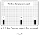
- FIG. 6 is a schematic diagram of settings of a low frequency magnetic field receive coil according to this application.
- at least three low frequency magnetic field receive coils may be disposed on the wireless charging receive coil.
- the low frequency magnetic field receive coil may be disposed on a side of a receive coil of the wireless charging receive apparatus 1000 toward a transmit coil of the wireless charging transmit apparatus 1010. It may be understood that positions of the low frequency magnetic field receive coils in FIG. 6 are merely examples. In a specific application scenario, the positions of the low frequency magnetic field receive coils may be set according to an actual application scenario requirement. This is not limited herein.
- the low frequency magnetic field receive coil may be a coil wound around a magnetic rod.
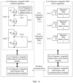
- FIG. 7 is a schematic diagram of a structure of a positioning system based on a low frequency magnetic field according to this application.
- the positioning system based on a low frequency magnetic field provided in this application may include a low frequency magnetic field transmit apparatus 700 and a low frequency magnetic field receive apparatus 710.
- the low frequency magnetic field transmit apparatus 700 includes a low frequency magnetic field transmit coil 701, a conflict detect coil 702, and a magnetic field generation detection control module 703.
- the low frequency magnetic field receive apparatus 710 includes a low frequency magnetic field receive coil 711 and a magnetic field detection control module 712.
- the magnetic field generation detection control module 703 may be integrated with a control module of a wireless charging transmit apparatus, or may be an independent function module.
- the magnetic field detection control module 712 may be integrated with a control module of a wireless charging receive apparatus, or may be an independent function module. This may be specifically determined according to an actual application scenario. This is not limited herein.
- the magnetic field generation detection control module 703 may include a low frequency magnetic field generate circuit, a low frequency magnetic field transmit-end control module, a low frequency magnetic field transmit-end communications module, and a magnetic field conflict detect circuit.
- the magnetic field detection control module 712 may include a low frequency magnetic field signal detect circuit, a low frequency magnetic field receive-end control module, a low frequency magnetic field receive-end communications module, and the like. Descriptions of specific functions of the parts are as follows:
- the low frequency magnetic field transmit coil is configured to: when the conflict detect coil detects that a low frequency magnetic field channel is not occupied, transmit an alternating low frequency magnetic field (for ease of description, an example in which a low frequency magnetic field signal generated in this case may be a first low frequency magnetic field signal is used for description), have magnetic induction with the low frequency magnetic field receive coil of the low frequency magnetic field receive apparatus, and transfer energy through magnetic coupling, to transmit the low frequency magnetic field signal to the low frequency magnetic field receive coil.
- an alternating low frequency magnetic field for ease of description, an example in which a low frequency magnetic field signal generated in this case may be a first low frequency magnetic field signal is used for description
- the low frequency magnetic field generate circuit includes an inverter circuit and a capacitor.
- a high frequency alternating voltage is generated by using the inverter circuit, and then is provided for the capacitor and the low frequency magnetic field transmit coil.
- the capacitor and the low frequency magnetic field transmit coil form a series resonant network, to generate high frequency series resonance.
- the conflict detect coil is configured to sense a low frequency magnetic field signal, to determine whether a low frequency magnetic field signal of an adjacent parking space is sensed.
- the magnetic field conflict detect circuit is configured to detect, based on the low frequency magnetic field signal sensed by the conflict detect coil, whether the adjacent parking space is transmitting a low frequency magnetic field signal.
- the magnetic field conflict detect circuit does not need external power supply (excitation). If another low frequency magnetic field signal is automatically sensed, the sensed low frequency magnetic field signal is correspondingly processed and then transmitted to the low frequency magnetic field transmit-end control module.
- the low frequency magnetic field transmit-end control module is configured to: control the low frequency magnetic field generate circuit and the magnetic field conflict detect circuit, control connection and disconnection of a controllable switch transistor in the inverter circuit in the low frequency magnetic field generate circuit, and control a signal detected by the magnetic field conflict detect circuit.
- the low frequency magnetic field transmit-end communications module is configured to send and receive information exchanged between the low frequency magnetic field transmit apparatus and the low frequency magnetic field receive apparatus in conflict detection.
- the information includes a signal length of the low frequency magnetic field signal transmitted by the low frequency magnetic field transmit coil, and the like.
- the low frequency magnetic field receive coil is configured to receive, through electromagnetic induction, a low frequency magnetic field signal transmitted by the low frequency magnetic field transmit coil.
- the low frequency magnetic field signal detect circuit is configured to: detect a low frequency magnetic field signal received by the low frequency magnetic field receive coil, and provide the low frequency magnetic field signal for the low frequency magnetic field receive-end control module for processing.
- the low frequency magnetic field receive-end control module is configured to: process the low frequency magnetic field signal detected by the low frequency magnetic field signal detect circuit, and generate a related control instruction.
- the low frequency magnetic field receive-end communications module is configured to send and receive information exchanged between the low frequency magnetic field transmit apparatus and the low frequency magnetic field receive apparatus in conflict detection.
- the information includes a signal length of the low frequency magnetic field signal transmitted by the low frequency magnetic field transmit apparatus, and the like.
- information sent or received by the low frequency magnetic field receive-end communications module in the low frequency magnetic field receive apparatus or the low frequency magnetic field transmit-end communications module in the low frequency magnetic field transmit apparatus is explained by using a communication protocol jointly followed by both parties. Details are not described below.
- the foregoing operations performed by the low frequency magnetic field generate circuit, the low frequency magnetic field transmit-end control module, the low frequency magnetic field transmit-end communications module, and the magnetic field conflict detect circuit are described by using the magnetic field generation detection control module 703 as an execution body in an example.
- the foregoing operations performed by the low frequency magnetic field signal detect circuit, the low frequency magnetic field receive-end control module, and the low frequency magnetic field receive-end communications module are described by using the magnetic field detection control module 712 as an execution body in an example.
- FIG. 8 is a schematic diagram of an application scenario of a positioning system based on a low frequency magnetic field according to this application.
- the positioning system provided in this application may be applied in guiding alignment in a wireless charging parking process of an electric vehicle.
- this application scenario it is assumed that there are a parking space 1, a parking space 2, and a parking space 3, a power transmit coil of a wireless charging transmit apparatus is disposed at each parking space, and a vehicle on which a wireless charging receive apparatus is installed needs to be charged at the parking space.
- a guiding alignment function is enabled.
- a position relationship of a power receive coil disposed on the vehicle relative to the power transmit coil disposed at the parking space may be detected, and further a driver or an automatic parking system is assisted in guiding alignment based on the position relationship.
- a low frequency magnetic field transmit apparatus for guiding alignment is disposed on a power transmit coil at each of the plurality of parking spaces.
- a low frequency magnetic field receive apparatus is disposed on the vehicle. In a guiding alignment process for parking the vehicle, a target is parking the vehicle at the parking space 2.
- the low frequency magnetic field receive apparatus on the vehicle may detect a low frequency magnetic field signal from the parking space 1 or the parking space 3 (that is, a low frequency magnetic field signal transmitted by the low frequency magnetic field transmit apparatus at the parking space 1 or the parking space 3).
- the positioning system provided in this application may perform guiding alignment based on conflict detection.
- the low frequency magnetic field transmit apparatus for guiding alignment may be installed on the power transmit coil of the wireless charging transmit apparatus.
- At least one (assuming two) low frequency magnetic field transmit coil for guiding alignment (for example, LtxA and LtxB disposed on the power transmit coil at the parking space 1, Ltx1 and Ltx2 disposed on the power transmit coil at the parking space 2, and Ltxa and Ltxb disposed on the power transmit coil at the parking space) and one conflict detect coil for conflict detection (for example, Ltx3) are disposed on the power transmit coil.
- a magnetic field generation detection control circuit including a low frequency magnetic field generate circuit, a magnetic field conflict detect circuit, a low frequency magnetic field transmit-end control module, and a low frequency magnetic field transmit-end communications module is also installed on the power transmit coil.
- the low frequency magnetic field receive apparatus for guiding alignment is installed on the power receive coil.
- At least three (assuming four) low frequency magnetic field receive coils are installed on the wireless charging receive coil.
- a magnetic field detection control circuit including a low frequency magnetic field detect circuit, a low frequency magnetic field receive-end control module, and a low frequency magnetic field receive-end communications module is also installed on the power receive coil.
- the positioning system based on a low frequency magnetic field provided in this application is described by using an example in which the positioning system based on a low frequency magnetic field is set in the wireless charging system at the parking space 2.
- the positioning system based on a low frequency magnetic field includes the low frequency magnetic field transmit apparatus disposed on the wireless charging transmit apparatus at the parking space 2 and the low frequency magnetic field receive apparatus disposed on the wireless charging receive apparatus at the parking space 2. Details are not described below.
- FIG. 9 is a schematic diagram of a hardware structure of a positioning system based on a low frequency magnetic field according to this application.
- a magnetic field generation detection control module in a low frequency magnetic field transmit apparatus may include a low frequency magnetic field detect circuit and a first capacitor (for example, Ctx3).
- a conflict detect coil (for example, Ltx3) is connected in parallel to Ctx3 to obtain a parallel resonant circuit.
- the parallel resonant circuit is connected to the low frequency magnetic field detect circuit.
- Ctx3 herein and the low frequency magnetic field detect circuit may form a magnetic field conflict detect circuit, a magnetic field conflict detect apparatus and the conflict detect coil form the magnetic field conflict detect apparatus, and the magnetic field conflict detect apparatus is connected to a low frequency magnetic field transmit-end control module.
- the low frequency magnetic field transmit apparatus provided in this application includes at least one low frequency magnetic field transmit coil. As shown in FIG. 9 , it is assumed that the low frequency magnetic field transmit apparatus includes two low frequency magnetic field transmit coils: Ltx1 and Ltx2, and Ltx1 and Ltx2 are respectively connected in series to a capacitor Ctxl and a capacitor Ctx2 to form a series resonant circuit.
- a direct current power supply Udc1, a half bridge inverter circuit including switch transistors Q1 and Q2, and a capacitor Ctxl form a low frequency magnetic field generate circuit of Ltx1.
- a direct current power supply Udc2, a half bridge inverter circuit including switch transistors Q3 and Q4, and a capacitor Ctx2 form a low frequency magnetic field generate circuit of Ltx2.
- the low frequency magnetic field generate circuits of Ltx1 and Ltx2 are connected to the low frequency magnetic field transmit-end control module.
- the low frequency magnetic field transmit-end control module controls connection and disconnection of the switch transistors (Q1 and Q2, or Q3 and Q4) in the half bridge inverter circuit, to convert a direct current into an alternating current with the same frequency as a resonant frequency of the series resonant circuit.
- the series resonant circuit generates series resonance under a function of the alternating current, so that Ltx1 or Ltx2 generates an alternating magnetic field.
- the low frequency magnetic field transmit-end control module controls the switch transistors in the half bridge inverter circuit, so that Ltx1 and Ltx2 sequentially transmit the alternating magnetic fields as one frame of a low frequency magnetic field signal.
- Total duration of transmitting magnetic field signals by Ltx1 and Ltx2 is agreed-on duration.
- signal lengths of the low frequency magnetic field signals transmitted by Ltx1 and Ltx2 are agreed-on signal lengths.
- the low frequency magnetic field transmit apparatus may transmit the agreed-on signal lengths to a low frequency magnetic field receive apparatus.
- the conflict detect apparatus includes a conflict detect coil (that is, Ltx3) and a magnetic field conflict detect circuit, and is configured to detect whether another parking space transmits a low frequency magnetic field signal.
- Ltx3 and Ctx3 form a parallel resonant circuit.
- the parallel resonant circuit is connected to the low frequency magnetic field detect circuit, to enhance a detection capability of the conflict detect coil for a weak signal.
- the low frequency magnetic field detect circuit may detect a signal length of a low frequency magnetic field signal sensed by the conflict detect coil (for ease of description, description may be provided by using an example in which the low frequency magnetic field signal sensed by the conflict detect coil is used as a background signal), send the signal length to the low frequency magnetic field transmit-end control module for determining, and determine whether the sensed low frequency magnetic field signal is a low frequency magnetic field signal transmitted by an adjacent parking space. If it is determined that the low frequency magnetic field signal sensed by the conflict detect coil is the low frequency magnetic field signal transmitted by the adjacent parking space, the low frequency magnetic field transmit apparatus may further send the signal length of the background signal to the low frequency magnetic field receive apparatus.
- An implementation of the low frequency magnetic field detect circuit may be determined according to an actual application scenario.
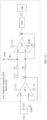
- FIG. 10 is a schematic diagram of a circuit of a low frequency magnetic field detect circuit according to this application. As shown in FIG. 10 , alternating voltages exist at two ends of the parallel resonant network (that is, a parallel resonant network formed by Ltx3 and Ctx3 connected in parallel) and have positive and negative values.
- An output impedance of the parallel resonant network is amplified to U1 by using a voltage follower circuit of an operational amplifier AP1, and then a direct current bias is added to an output U2 by using an operational amplifier AP2 and resistors R1, R2, and R3, so that an output voltage of the operational amplifier AP2 falls within a voltage range from 0 V to 3.3 V
- a digital variable U3 is obtained, and U3 is input to digital signal processing (digital signal process, DSP) for processing.
- the DSP may indicate a low frequency magnetic field transmit-end control module.
- the DSP performs fast fourier transform (fast fourier transform, FFT) analysis on U3.
- the DSP determines that the parallel resonant circuit senses a low frequency magnetic field signal of another parking space. In other words, it may be considered as that there is the low frequency magnetic field transmit signal of another parking space.
- the DSP may further determine duration of a signal based on duration in which the signal amplitude is greater than or equal to the preset signal amplitude threshold, and determine the signal duration as the signal length of the sensed background signal.
- four low frequency magnetic field receive coils such as Lrx1, Lrx2, Lrx3, and Lrx4 may be used in the low frequency magnetic field receive apparatus.
- capacitors: Crx1, Crx2, Crx3, and Crx4 may be respectively connected in parallel to Lrx1, Lrx2, Lrx3, and Lrx4 to obtain the parallel resonant circuits.
- the parallel resonant circuits are connected to the magnetic field detect circuit, to enhance a detection capability of the low frequency magnetic field receive coil for a weak signal.
- a parallel resonant circuit including Lrx1 and Crx1 is connected to a magnetic field detect circuit 1.
- a parallel resonant circuit including Lrx2 and Crx2 is connected to a magnetic field detect circuit 2.
- a parallel resonant circuit including Lrx3 and Crx3 is connected to a magnetic field detect circuit 3.
- a parallel resonant circuit including Lrx4 and Crx4 is connected to a magnetic field detect circuit 4.
- the magnetic field detect circuits (including the magnetic field detect circuit 1, the magnetic field detect circuit 2, the magnetic field detect circuit 3, and the magnetic field detect circuit 4) may detect an amplitude and a time length of a signal sensed by the low frequency magnetic field receive coil, and then send the amplitude and the time length to a low frequency magnetic field receive-end control module.
- the low frequency magnetic field receive-end control module calculates relative positions of the low frequency magnetic field transmit coil and the low frequency magnetic field receive coil based on the signal amplitude.
- a communications module, and a low frequency magnetic field transmit-end communications module and a low frequency magnetic field receive-end communications module shown in FIG. 9 may be separately configured in the low frequency magnetic field transmit apparatus and the low frequency magnetic field receive apparatus.
- the low frequency magnetic field transmit-end communications module and the low frequency magnetic field receive-end communications module may implement communication by using technologies such as Wi-Fi, Bluetooth, zigbee (zigbee), and radio frequency identification (radio frequency identification, RFID). This may be specifically determined according to an actual application scenario. This is not limited herein.
- FIG. 11 is a schematic diagram of another hardware structure of a positioning system based on a low frequency magnetic field according to this application. As shown in FIG. 11 , a low frequency magnetic field transmit coil and a conflict detect coil of the low frequency magnetic field transmit apparatus are multiplexed. In other words, in this case, the low frequency magnetic field transmit coil and the conflict detect coil are the same coil in the low frequency magnetic field transmit apparatus, for example, Ltx1.
- a connection mode of a switch transistor of an inverter circuit may be changed to implement function switching of transmission of a low frequency magnetic field signal and conflict detection of a low frequency magnetic field signal.
- a magnetic field generation detection control module in a low frequency magnetic field transmit apparatus includes a low frequency magnetic field detect circuit, a direct current power supply Udc1, a first switch Q1, a second switch Q2, and a first capacitor Ctxl.
- Ltx1 is connected in parallel to Ctxl to obtain a parallel resonant circuit.
- the parallel resonant circuit is connected to the low frequency magnetic field detect circuit.
- a low frequency magnetic field transmission control module (that is, a low frequency magnetic field transmit-end control module) is configured to control connection or disconnection of Q1 and Q2, to control Ltx1 to sense a low frequency magnetic field signal, or control Ltx1 to transmit a low frequency magnetic field signal.
- the low frequency magnetic field receive apparatus may use three low frequency magnetic field receive coils and a magnetic field detect circuit instead.
- the parallel resonant circuit including Lrx1 and Crx1 is connected to the magnetic field detect circuit 1.
- the parallel resonant circuit including Lrx2 and Crx2 is connected to the magnetic field detect circuit 2.
- the parallel resonant circuit including Lrx3 and Crx3 is connected to the magnetic field detect circuit 3.
- switch mode switching of the inverter circuit from a low frequency magnetic field transmission mode to a conflict detection mode may be added before conflict detection, and a switch mode switching process of the inverter circuit from the conflict detection mode to the low frequency magnetic field transmission mode may be added after conflict detection.
- Ltx1 works in the conflict detection mode
- the low frequency magnetic field transmit-end control module controls Q1 to be disconnected and Q2 to be connected.
- Ltx1 and Ctxl form a parallel resonant circuit.
- a magnetic field strength signal is obtained at Ctxl by using the low frequency magnetic field detect circuit, to determine whether a low frequency magnetic field channel is occupied by a low frequency magnetic field transmit apparatus of a remaining parking space.
- the low frequency magnetic field transmit-end control module controls Q1 and Q2 to be connected in an alternating manner, and Ltx1 and Ctxl form a series compensation circuit and transmit a magnetic field.
- the low frequency magnetic field transmit coil and the conflict detect coil are multiplexed, so that one coil can be omitted, to reduce implementation costs of a positioning system based on a low frequency magnetic field and save space of the low frequency magnetic field transmit apparatus, thereby implementing high applicability.
- a wireless charging transmit apparatus of a wireless charging system is disposed at the parking space 2.
- a power transmit coil is disposed in the wireless charging transmit apparatus.
- a wireless charging receive apparatus of a wireless charging system is disposed on a vehicle.
- a power receive coil is disposed in the wireless receive apparatus.
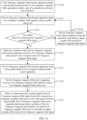
- the low frequency magnetic field transmit-end control module makes a response and agrees to enable the positioning function by using the low frequency magnetic field transmit-end communications module, and performs initialization.
- a request for enabling the low frequency magnetic field guiding alignment function may also be sent by the low frequency magnetic field transmit apparatus. This may be specifically determined according to an actual application scenario. This is not limited herein. For example, if the low frequency magnetic field receive apparatus is installed at the vehicle end, the request is preferably sent by the low frequency magnetic field receive apparatus, because guiding alignment is enabled only when the vehicle is close and requires guidance, to implement higher applicability.
- the low frequency magnetic field receive-end control module sends one piece of information to the low frequency magnetic field transmit-end control module by using the low frequency magnetic field receive-end communications module.
- the information is interpreted as a request to use the low frequency magnetic field to perform guiding alignment.
- information sent or received by the low frequency magnetic field receive apparatus or the low frequency magnetic field transmit apparatus is also explained according to the communication protocol jointly followed by both parties. Details are not described below.
- the low frequency magnetic field transmit-end control module receives, by using the low frequency magnetic field transmit-end communications module, request information that is sent by a low frequency magnetic field receive end for enabling guiding alignment.
- the low frequency magnetic field transmit-end control module makes a response to the low frequency magnetic field receive-end control module.
- the response information includes information indicating that the low frequency magnetic field is allowed for guiding alignment, identification information of the low frequency magnetic field transmit coil (for example, Ltx1 and Ltx2), a coil size, relative positions of the low frequency magnetic field transmit coil and the power transmit coil, and the like.
- the identification information of the low frequency magnetic field transmit coil is used to distinguish between the low frequency magnetic field transmit coils, for example, Ltx1 and Ltx2.
- the coil size needs to be used when the relative positions of the low frequency magnetic field transmit coil and the low frequency magnetic field receive coil are calculated. Relative positions of the power transmit coil and each of Ltx1 and Ltx2 are used to finally determine relative positions of the power transmit coil and the power receive coil.
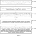
- the conflict detect coil senses a low frequency magnetic field signal.
- the magnetic field generation detection control module may control the low frequency magnetic field transmit coil to transmit a low frequency magnetic field signal (that is, a first low frequency magnetic field signal).
- the low frequency magnetic field receive coil receives a low frequency magnetic field signal.
- the magnetic field detection control module determines relative positions of the low frequency magnetic field transmit coil and the low frequency magnetic field receive coil based on signal strength of the first low frequency magnetic field signal.
- the magnetic field detection control module may further determine the relative positions of the power transmit coil and the power receive coil based on the relative positions of the low frequency magnetic field transmit coil and the power transmit coil and the relative positions of the low frequency magnetic field receive coil and the power receive coil, and may further present the relative positions of the power transmit coil and the power receive coil to the driver or the automatic driving system to implement guiding alignment between the power transmit coil and the power receive coil.
- the low frequency magnetic field transmit apparatus before transmitting the low frequency magnetic field signal, detects, by using the conflict detect coil, whether there is a low frequency magnetic field signal, to determine whether a low frequency magnetic field channel is occupied by a low frequency magnetic field transmit apparatus at another parking space, and transmits the low frequency magnetic field signal only when the low frequency magnetic field channel is not occupied. In this case, if a plurality of low frequency magnetic field transmit apparatuses detect that the low frequency magnetic field channel is not occupied, the low frequency magnetic field transmit apparatuses simultaneously transmit low frequency magnetic field signals at a large probability, thereby causing a conflict.
- the magnetic field generation detection control module of the low frequency magnetic field transmit apparatus may further generate an initial value of a countdown and start the countdown.
- the magnetic field generation detection control module controls the low frequency magnetic field transmit coil to transmit the first low frequency magnetic field signal.
- the magnetic field generation detection control module generates the initial value of the countdown when the positioning function is enabled.
- the initial value may be a random number.
- the initial value may also be an agreed-on count value.
- the initial value that is of the countdown and that is generated by the low frequency magnetic field transmit apparatus at the parking space is a count value (for example, one initial value randomly selected from a plurality of initial values).
- Initial values that are of countdowns and that are generated by low frequency magnetic field transmit apparatuses at different parking spaces are different (for example, the initial values corresponding to different parking spaces are different count values randomly selected from the plurality of initial values).
- the initial value of the countdown may also be determined in other manners. This is not limited herein.
- the magnetic field generation detection control module if the magnetic field generation detection control module detects that the conflict detect coil senses a low frequency magnetic field signal (that is, a second low frequency magnetic field signal) transmitted by the low frequency magnetic field transmit apparatus at the adjacent parking space, the magnetic field generation detection control module stops the countdown and detects a signal length of the second low frequency magnetic field signal, and continues the countdown when the detection of the signal length of the second low frequency magnetic field signal is completed.
- the detection of the second low frequency magnetic field signal may be implemented by using the low frequency magnetic field detect circuit shown in FIG. 10 . Details are not described herein again.
- the magnetic field generation detection control module controls the low frequency magnetic field transmit coil to transmit the low frequency magnetic field signal.
- the signal length of the low frequency magnetic field signal transmitted by the low frequency magnetic field transmit coil may be an agreed-on signal length.
- the agreed-on signal length of the low frequency magnetic field signal transmitted by the low frequency magnetic field transmit coil is adjusted, so that the signal length (that is, the first signal length) of the low frequency magnetic field signal (that is, the first low frequency magnetic field signal) transmitted by the low frequency magnetic field transmit coil is different from the signal length (that is, a second signal length) of the second low frequency magnetic field signal.
- the second low frequency magnetic field signal represents a background signal detected by the conflict detect coil
- the second signal length represents a signal length of the background signal.
- the conflict detect coil detects a plurality of background signals, there are a plurality of second low frequency magnetic field signals in this case, and the plurality of second low frequency magnetic field signals have a plurality of signal lengths (that is, the plurality of second signal lengths are different).
- the signal length of the low frequency magnetic field signal transmitted by the low frequency magnetic field transmit coil is different from the signal lengths of the second low frequency magnetic field signals.
- the low frequency magnetic field transmit apparatus may send the first signal length to the magnetic field detection control module (specifically, the low frequency magnetic field receive-end communications module in the magnetic field detection control module) of the low frequency magnetic field receive apparatus by using the low frequency magnetic field transmit-end communications module.
- the magnetic field detection control module determines that the low frequency magnetic field signal received by the low frequency magnetic field receive coil is the first low frequency magnetic field signal, and may further determine the relative positions of the low frequency magnetic field transmit coil and the low frequency magnetic field receive coil based on the signal strength of the first low frequency magnetic field signal.
- the low frequency magnetic field transmit apparatus end has at least one low frequency magnetic field transmit coil
- the low frequency magnetic field receive apparatus end has at least three low frequency magnetic field receive coils.
- a reference point is a baseline point (0,0) (it is assumed that a middle point of the power transmit coil is the baseline point).
- Each receive coil has coordinates: (X, Y) relative to the transmit coil.
- the low frequency magnetic field transmit coil has a relative position relative to the power transmit coil.
- the three low frequency magnetic field receive coils have relative positions relative to the power receive coil.
- the relative positions of the power receive coil and the power transmit coil may be obtained based on relative positions of each of the three low frequency magnetic field receive coils and the low frequency magnetic field transmit coil, a position relationship between the low frequency magnetic field transmit coil and the power transmit coil, and a position relationship between the low frequency magnetic field receive coil and the power receive coil.
- FIG. 12 is a schematic flowchart of a positioning method based on a low frequency magnetic field according to this application.
- the positioning method based on a low frequency magnetic field provided in this application is applicable to the foregoing positioning system based on a low frequency magnetic field (as shown in FIG. 7 ).
- the positioning method based on a low frequency magnetic field provided in this application may include the following steps: S120: The low frequency magnetic field transmit apparatus enables a positioning function based on a low frequency magnetic field.
- the low frequency magnetic field receive apparatus may request the low frequency magnetic field transmit apparatus to enable a low frequency magnetic field guiding alignment function (that is, enable a positioning function based on a low frequency magnetic field).
- the low frequency magnetic field transmit apparatus makes a response and agrees to enable the positioning function, and performs initialization.
- the low frequency magnetic field transmit apparatus senses a low frequency magnetic field signal by using a conflict detect coil.
- the low frequency magnetic field transmit apparatus controls a low frequency magnetic field transmit coil to transmit a first low frequency magnetic field signal.
- the low frequency magnetic field transmit apparatus can sense the low frequency magnetic field signal by using the conflict detect coil.
- the low frequency magnetic field transmit apparatus may control the low frequency magnetic field transmit coil to transmit the low frequency magnetic field signal (that is, the first low frequency magnetic field signal).
- the first low frequency magnetic field signal is used to determine relative positions of the low frequency magnetic field transmit coil and a low frequency magnetic field receive coil.
- the low frequency magnetic field receive apparatus receives the low frequency magnetic field signal by using the low frequency magnetic field receive coil.
- the low frequency magnetic field receive apparatus determines the relative positions of the low frequency magnetic field transmit coil and the low frequency magnetic field receive coil based on signal strength of the first low frequency magnetic field signal.
- the low frequency magnetic field receive apparatus may receive the low frequency magnetic field signal by using the low frequency magnetic field receive coil.
- the low frequency magnetic field receive apparatus determines the relative positions of the low frequency magnetic field transmit coil and the low frequency magnetic field receive coil based on the signal strength of the first low frequency magnetic field signal.
- the low frequency magnetic field receive apparatus may further determine relative positions of a power transmit coil and a power receive coil based on the relative positions of the low frequency magnetic field transmit coil and the power transmit coil and the relative positions of the low frequency magnetic field receive coil and the power receive coil, and may further present the relative positions of the power transmit coil and the power receive coil to the driver or an automatic driving system to implement guiding alignment between the power transmit coil and the power receive coil.
- a low frequency magnetic field receive apparatus on the vehicle senses a low frequency magnetic field signal transmitted by a low frequency magnetic field transmit apparatus at an adjacent parking space, to reduce mutual interference when the low frequency magnetic field receive apparatus receives low frequency magnetic field signals in a positioning process of the power receive coil and the power transmit coil at the adjacent parking space. This improves positioning accuracy of the power transmit coil and the power receive coil in the wireless charging system. Charging efficiency of the wireless charging system can be improved, to implement higher applicability.
- FIG. 13 is another schematic flowchart of a positioning method based on a low frequency magnetic field according to this application.
- This application provides a positioning method based on timer contention. A random number is introduced to reduce a conflict occurrence probability, to improve positioning accuracy of a low frequency magnetic field transmit coil and a low frequency magnetic field receive coil, thereby implementing higher applicability.
- the positioning method based on a low frequency magnetic field provided in this application may include the following steps:
- a low frequency magnetic field transmit apparatus enables a positioning function based on a low frequency magnetic field, generates an initial value of a countdown, and starts the countdown.
- the low frequency magnetic field transmit apparatus senses a low frequency magnetic field signal by using a conflict detect coil.
- a low frequency magnetic field receive apparatus may request the low frequency magnetic field transmit apparatus to enable a low frequency magnetic field guiding alignment function (that is, enable a positioning function based on a low frequency magnetic field).
- the low frequency magnetic field transmit apparatus makes a response and agrees to enable the positioning function, and performs initialization.
- the low frequency magnetic field transmit apparatus receives request information that is sent by the low frequency magnetic field receive apparatus for enabling guiding alignment.
- the low frequency magnetic field transmit apparatus makes a response to the low frequency magnetic field receive apparatus.
- the response information includes information indicating that the low frequency magnetic field is allowed for guiding alignment (that is, a positioning function based on a low frequency magnetic field is allowed to be enabled), identification information of the low frequency magnetic field transmit coil (for example, Ltx1 and Ltx2), a coil size, relative positions of the low frequency magnetic field transmit coil and the power transmit coil, and the like.
- identification information of the low frequency magnetic field transmit coil is used to distinguish between the low frequency magnetic field transmit coils, for example, Ltx1 and Ltx2.
- the coil size is used when relative positions of the low frequency magnetic field transmit coil and the low frequency magnetic field receive coil are calculated.
- Relative positions of the power transmit coil and each of Ltx1 and Ltx2 are used to finally determine relative positions of the power transmit coil and the power receive coil.
- the low frequency magnetic field transmit apparatus may generate a random number t 0 .
- a timer starts a countdown, and an initial value of the countdown is t 0 .
- step S132 Determine whether the conflict detect coil senses a low frequency magnetic field signal. If a determining result is that the conflict detect coil does not sense the low frequency magnetic field signal, perform step S133. If a determining result is that the conflict detect coil senses the low frequency magnetic field signal, perform step S134.
- the low frequency magnetic field transmit apparatus controls the low frequency magnetic field transmit coil to transmit a first low frequency magnetic field signal.
- the low frequency magnetic field transmit apparatus stops the countdown, and detects a signal length of the sensed low frequency magnetic field signal.
- the low frequency magnetic field transmit apparatus may detect, by using the conflict detect coil (for example, Ltx3), whether a low frequency magnetic field transmit apparatus at another parking space is transmitting a low frequency magnetic field signal. If the low frequency magnetic field signal is not sensed by using the conflict detect coil and the countdown ends, the low frequency magnetic field transmit apparatus controls the low frequency magnetic field transmit coil to transmit the first low frequency magnetic field signal. If the low frequency magnetic field signal is sensed by using the conflict detect coil, the low frequency magnetic field transmit apparatus stops the countdown, and detects a signal length of the sensed low frequency magnetic field signal. If the low frequency magnetic field transmit apparatus does not detect a low frequency magnetic field signal transmitted by a low frequency magnetic field apparatus at another parking space after completing detection of the signal length of the low frequency magnetic field signal, the low frequency magnetic field transmit apparatus continues the countdown.
- the conflict detect coil for example, Ltx3
- the low frequency magnetic field transmit apparatus (for example, a low frequency magnetic field transmit apparatus at a parking space 2) in this positioning system may transmit a frame of a low frequency magnetic field; and may transmit, by using the low frequency magnetic field transmit coil (for example, Ltx1 and Ltx2), a low frequency magnetic field signal with a preset controllable feature (for example, 4 ms) whose signal length is different from a signal length of a sensed background signal (for example, a second low frequency magnetic field signal).
- a low frequency magnetic field transmit-end control module in the low frequency magnetic field transmit apparatus may transmit control signals to two half-bridge inverter circuits in a hardware structure shown in FIG. 9 or FIG.
- Low frequency magnetic field transmit coils Ltx1 and Ltx2 transmit low frequency magnetic field signals in a time division manner. To be specific, when Ltx1 transmits signals, Ltx2 does not transmit signals, and this process is stopped after 2 ms; then, when Ltx2 transmits signals, Ltx1 does not transmit signals, and this process is stopped after 2 ms. After transmitting the low frequency magnetic field signal, the low frequency magnetic field transmit apparatus generates a random number again, and repeats the foregoing procedure.
- the low frequency magnetic field transmit apparatus sends a first signal length to the low frequency magnetic field receive apparatus.
- the low frequency magnetic field receive apparatus receives a low frequency magnetic field signal by using the low frequency magnetic field receive coil.
- the low frequency magnetic field receive apparatus determines the relative positions of the low frequency magnetic field transmit coil and the low frequency magnetic field receive coil based on signal strength of the received low frequency magnetic field signal.
- the low frequency magnetic field transmit apparatus may further send the signal length of the first low frequency magnetic field signal (that is, the first signal length, for example, 4 ms) as an agreed-on feature to the low frequency magnetic field receive apparatus, and the low frequency magnetic field receive apparatus may receive the first signal length from the low frequency magnetic field transmit apparatus.
- the low frequency magnetic field receive apparatus learns of signal length features of the low frequency magnetic field signals transmitted by the low frequency magnetic field transmit coils of the low frequency magnetic field transmit apparatus in this positioning system.
- the low frequency magnetic field receive apparatus obtains signal strength of low frequency magnetic field signals received by low frequency magnetic field receive coils: Lrx1, Lrx2, Lrx3, and Lrx4; and if the signal length of the low frequency magnetic field signal received by the low frequency magnetic field receive coil is not the agreed-on signal length (that is, 4 ms), does not process data of the signal strength of the low frequency magnetic field signal. If the signal length of the low frequency magnetic field signal received by the low frequency magnetic field receive coil is the agreed-on signal length (that is, 4 ms), it may be determined that the low frequency magnetic field signal is a low frequency magnetic field signal (that is, the first low frequency magnetic field signal) transmitted by the low frequency magnetic field transmit apparatus at the parking space 2.
- the low frequency magnetic field receive apparatus may detect signal strength in first 2 ms of the low frequency magnetic field signal and signal strength in later 2 ms of the low frequency magnetic field signal, to determine the signal strength of the low frequency magnetic field signals transmitted by Ltx1 and Ltx2.
- the low frequency magnetic field receive apparatus may calculate relative positions of each of Ltx1 and Ltx2 and each of Lrx1, Lrx2, Lrx3, and Lrx4 based on the signal strength of the low frequency magnetic field signals received by Ltx1 and Ltx2 and sizes of Ltx1 and Ltx2. Further, the relative positions of the power transmit coil and the receive coil may be calculated based on relative positions of each of Ltx1 and Ltx2 and a power transmit coil of a wireless charging transmit apparatus, and relative positions of each of Lrx1, Lrx2, Lrx3, and Lrx4 and a power receive coil of a wireless charging receive apparatus.
- the low frequency magnetic field receive apparatus may further determine the relative positions of the power transmit coil and the power receive coil based on the relative positions of the low frequency magnetic field transmit coil and the power transmit coil and relative positions of the low frequency magnetic field receive coil and the power receive coil. This implementation may be determined according to an actual application scenario. This is not limited herein.
- the low frequency magnetic field receive apparatus in the vehicle senses a low frequency magnetic field signal transmitted by a low frequency magnetic field transmit apparatus at an adjacent parking space, to reduce mutual positioning interference between the power transmit coil at the adjacent parking space and the power receive coil. This improves positioning accuracy of the power transmit coil and the power receive coil in the wireless charging system. Charging efficiency of the wireless charging system can be improved, to implement higher applicability.
Abstract
Description
- This application claims priority to
Chinese Patent Application No. 202010687243.2, filed with the China National Intellectual Property Administration on July 16, 2020 - This application relates to the field of electromagnetic induction technologies, and in particular, to a positioning system and method based on a low frequency magnetic field, and a device.
- With aggravation of energy shortage and environmental pollution problems in modern society, an electric vehicle, as a new energy vehicle, attracts wide attention once launched. The electric vehicle is a vehicle powered by an in-vehicle power supply, using a motor to drive vehicle wheels, and complying with various requirements of road traffic and safety regulations. Wireless charging through magnetic coupling is a manner of charging a battery of the electric vehicle. The wireless charging through magnetic coupling means transferring electric energy by using coupled electric fields or coupled magnetic fields as a medium. A wireless charging system generally includes two separate components: respectively a power transmit apparatus and a power receive apparatus. The power transmit apparatus is located in a wireless charging station. The power receive apparatus is located in an electric vehicle. The power transmit apparatus and the power receive apparatus transfer energy through electromagnetic induction between a power transmit coil and a power receive coil. When the power transmit coil and the power receive coil are misaligned or an alignment degree does not meet a requirement, a charging power or power efficiency of the wireless charging system decreases. Therefore, how to determine relative positions of the power transmit coil and the power receive coil to improve the alignment degree between the power transmit coil and the power receive coil is one of key technical problems that currently need to be urgently resolved in the wireless charging system.
- In a research and practice process, the inventors of this application find that, in the conventional technologies, a low frequency magnetic field transmit coil is added to the power transmit apparatus end, and a control circuit corresponding to the low frequency magnetic field transmit coil drives the low frequency magnetic field transmit coil to generate an alternating low frequency magnetic field. A low frequency magnetic field receive coil is added to the power receive apparatus end, and the low frequency magnetic field receive coil generates an inducted voltage or an inducted current in the alternating magnetic field. Relative positions of the low frequency magnetic field transmit coil and the low frequency magnetic field receive coil are obtained based on signal strength of the inducted voltage or the inducted current. Relative positions of the power transmit coil and the power receive coil are obtained based on a position relationship between the low frequency magnetic field transmit coil and the power transmit coil and a position relationship between the low frequency magnetic field receive coil and the power receive coil. However, an effective range of the low frequency magnetic field is relatively large. Low frequency magnetic fields generated by low frequency magnetic field transmit coils of adjacent wireless charging stations interfere with each other. As a result, positioning accuracy of the low frequency magnetic field transmit coil and the low frequency magnetic field receive coil is low. Consequently, alignment accuracy of the power transmit coil and the power receive coil is low, and a charging power or power efficiency of the wireless charging system is low. Therefore, the wireless charging system has poor applicability.
- This application provides a positioning system and method based on a low frequency magnetic field, and a device, to improve positioning accuracy of a low frequency magnetic field transmit coil and a low frequency magnetic field receive coil, thereby implementing a simple operation and high applicability.
- According to a first aspect, this application provides a positioning system based on a low frequency magnetic field. The positioning system includes a low frequency magnetic field transmit apparatus and a low frequency magnetic field receive apparatus. The low frequency magnetic field transmit apparatus includes a low frequency magnetic field transmit coil, a conflict detect coil, and a magnetic field generation detection control module. The low frequency magnetic field receive apparatus includes a low frequency magnetic field receive coil and a magnetic field detection control module. The conflict detect coil is configured to sense a low frequency magnetic field signal. The magnetic field generation detection control module is configured to: when the conflict detect coil does not sense the low frequency magnetic field signal, control the low frequency magnetic field transmit coil to transmit a first low frequency magnetic field signal. Herein, before the low frequency magnetic field transmit apparatus transmits the low frequency magnetic field signal by using the low frequency magnetic field transmit coil, the low frequency magnetic field transmit apparatus may use the conflict detect coil to determine whether the low frequency magnetic field signal can be sensed. In other words, the low frequency magnetic field transmit apparatus uses the conflict detect coil to detect whether a low frequency magnetic field channel is occupied. The low frequency magnetic field transmit coil transmits a low frequency magnetic field signal when the low frequency magnetic field channel is not occupied, to avoid mutual interference caused when low frequency magnetic field transmit coils of different positioning systems transmit low frequency magnetic field signals. The low frequency magnetic field receive coil is configured to receive a low frequency magnetic field signal. The magnetic field detection control module is configured to: when it is determined that the low frequency magnetic field signal received by the low frequency magnetic field receive coil is the first low frequency magnetic field signal, determine relative positions of the low frequency magnetic field transmit coil and the low frequency magnetic field receive coil based on signal strength of the first low frequency magnetic field signal. In this application, the low frequency magnetic field receive apparatus receives only the low frequency magnetic field signal transmitted by the low frequency magnetic field transmit coil of this positioning system. In other words, when the low frequency magnetic field signal received by the low frequency magnetic field receive coil is the low frequency magnetic field signal transmitted by the low frequency magnetic field transmit coil of this positioning system, the low frequency magnetic field receive apparatus determines the relative positions of the low frequency magnetic field transmit coil and the low frequency magnetic field receive coil based on the signal strength of the low frequency magnetic field signal, to avoid interference from a low frequency magnetic field signal transmitted by a low frequency magnetic field transmit coil of another positioning system, thereby improving positioning accuracy.
- With reference to the first aspect, in a first possible implementation, the magnetic field generation detection control module is configured to: when a positioning function based on a low frequency magnetic field is enabled, generate an initial value of a countdown and start the countdown. The magnetic field generation detection control module is configured to: when the conflict detect coil does not sense the low frequency magnetic field signal and the countdown ends, control the low frequency magnetic field transmit coil to transmit the first low frequency magnetic field signal. In this application, the low frequency magnetic field transmit coil transmits the low frequency magnetic field signal when the conflict detect coil does not sense the low frequency magnetic field signal and the countdown ends, thereby reducing a probability that a conflict occurs when the low frequency magnetic field transmit coil and low frequency magnetic field transmit coil of another positioning system simultaneously transmit low frequency magnetic field signals.
- With reference to the first aspect, in a second possible implementation, the magnetic field generation detection control module is further configured to: when the conflict detect coil senses a second low frequency magnetic field signal, stop the countdown and detect a signal length of the second low frequency magnetic field signal, and continue the countdown when the detection of the signal length of the second low frequency magnetic field signal is completed. In this application, if the conflict detect coil senses a background signal, the magnetic field generation detection control module may pause the countdown, detect a signal length of the background signal, and then continue the countdown, to ensure that transmitting the low frequency magnetic field signal by the low frequency magnetic field transmit coil when the countdown ends does not conflict with transmitting the low frequency magnetic field signal by the low frequency magnetic field transmit coil of the another positioning system.
- With reference to the first possible implementation of the first aspect or the second possible implementation of the first aspect, in a third possible implementation, the initial value of the countdown is a random number. In this application, the initial value of the countdown is set to the random number, so that the following case can be avoided: Low frequency magnetic field transmit coils of a plurality of positioning systems simultaneously transmit low frequency magnetic field signals when it is detected that the low frequency magnetic field channel is not occupied. A simple operation and high applicability are implemented.
- With reference to the second possible implementation of the first aspect, in a fourth possible implementation, a first signal length of the first low frequency magnetic field signal is different from a second signal length of the second low frequency magnetic field signal. In this application, the signal length of the low frequency magnetic field signal transmitted by the low frequency magnetic field transmit coil may be an agreed-on signal length If the signal length of the background signal (that is, the second low frequency magnetic field signal) detected by the conflict detect coil is the same as the agreed-on signal length, the agreed-on signal length of the low frequency magnetic field signal transmitted by the low frequency magnetic field transmit coil is adjusted, so that the signal length (that is, the first signal length) of the low frequency magnetic field signal (that is, the first low frequency magnetic field signal) transmitted by the low frequency magnetic field transmit coil is different from the signal length (that is, the second signal length) of the second low frequency magnetic field signal. In this way, it can be ensured that the low frequency magnetic field signal received by the low frequency magnetic field receive apparatus is the low frequency magnetic field signal transmitted by the low frequency magnetic field transmit coil of this positioning system, to ensure positioning accuracy of the low frequency magnetic field transmit coil and the low frequency magnetic field receive coil.
- With reference to the fourth possible implementation of the first aspect, in a fifth possible implementation, the magnetic field generation detection control module is further configured to send the first signal length to the magnetic field detection control module. The magnetic field detection control module is configured to: when detecting that the signal length of the low frequency magnetic field signal received by the low frequency magnetic field receive coil is the same as the first signal length, determine that the low frequency magnetic field signal received by the low frequency magnetic field receive coil is the first low frequency magnetic field signal. In this application, the magnetic field detection control module determines, based on the signal length of the low frequency magnetic field signal received by the low frequency magnetic field receive coil, whether the low frequency magnetic field signal is the low frequency magnetic field signal transmitted by the low frequency magnetic field transmit coil of this positioning system, thereby implementing a simple operation.
- With reference to any one of the first aspect to the fifth possible implementation of the first aspect, in a sixth possible implementation, the magnetic field generation detection control module includes a low frequency magnetic field detect circuit and a first capacitor. The conflict detect coil is connected in parallel to the first capacitor to obtain a parallel resonant circuit. The parallel resonant circuit is connected to the low frequency magnetic field detect circuit.
- With reference to any one of the first aspect to the fifth possible implementation of the first aspect, in a seventh possible implementation, the low frequency magnetic field transmit coil and the conflict detect coil are the same coil. The magnetic field generation detection control module includes a low frequency magnetic field transmission control module, a low frequency magnetic field detect circuit, a direct current power supply, a first switch, a second switch, and a first capacitor. The coil is connected in parallel to the first capacitor to obtain a parallel resonant circuit. The parallel resonant circuit is connected to the low frequency magnetic field detect circuit. The first switch and the second switch are connected in series, and then are connected in parallel between two ends of the direct current power supply to obtain an inverter circuit. One end of the first capacitor is separately connected to a first switch and a second switch. The other end of the first capacitor is connected in series to the coil to obtain a series resonant circuit. The first capacitor and the inverter circuit form a low frequency magnetic field generate circuit of the coil. The low frequency magnetic field transmission control module is configured to control connection or disconnection of the first switch and the second switch to control the coil to sense the low frequency magnetic field signal or control the coil to transmit the first low frequency magnetic field signal. In this application, the low frequency magnetic field transmit coil and the conflict detect coil do not simultaneously work. Therefore, the conflict detect coil and the low frequency magnetic field transmit coil of the low frequency magnetic field transmit apparatus can be multiplexed, to simplify a system structure of the positioning system.
- According to a second aspect, this application provides a positioning method based on a low frequency magnetic field. The method is applicable to a positioning system based on a low frequency magnetic field. The positioning system includes a low frequency magnetic field transmit apparatus and a low frequency magnetic field receive apparatus. The method includes: The low frequency magnetic field transmit apparatus senses a low frequency magnetic field signal by using a conflict detect coil. If the low frequency magnetic field signal is not sensed by using the conflict detect coil, the low frequency magnetic field transmit apparatus controls a low frequency magnetic field transmit coil to transmit a first low frequency magnetic field signal. The low frequency magnetic field receive apparatus receives a low frequency magnetic field signal by using a low frequency magnetic field receive coil. When it is determined that the low frequency magnetic field signal received by using the low frequency magnetic field receive coil is the first low frequency magnetic field signal, the low frequency magnetic field receive apparatus determines relative positions of the low frequency magnetic field transmit coil and the low frequency magnetic field receive coil based on signal strength of the first low frequency magnetic field signal.
- With reference to the second aspect, in a first possible implementation, when a positioning function based on a low frequency magnetic field is enabled, the low frequency magnetic field transmit apparatus generates an initial value of a countdown and starts the countdown. If the low frequency magnetic field signal is not sensed by using the conflict detect coil and the countdown ends, the low frequency magnetic field transmit apparatus controls the low frequency magnetic field transmit coil to transmit the first low frequency magnetic field signal.
- With reference to the first possible implementation of the second aspect, in a second possible implementation, if the low frequency magnetic field signal is sensed by using the conflict detect coil, the low frequency magnetic field transmit apparatus stops the countdown and detects a signal length of the sensed low frequency magnetic field signal, and continues the countdown when the detection of the signal length of the sensed low frequency magnetic field signal is completed.
- With reference to the first possible implementation of the second aspect or the second possible implementation of the second aspect, in a third possible implementation, the initial value of the countdown is a random number.
- With reference to any one of the second aspect to the second possible implementation of the second aspect, in a fourth possible implementation, a first signal length of the first low frequency magnetic field signal is different from a second signal length of the sensed low frequency magnetic field signal. The method further includes: The low frequency magnetic field transmit apparatus sends the first signal length to the low frequency magnetic field receive apparatus. The low frequency magnetic field receive apparatus receives the first signal length from the low frequency magnetic field transmit apparatus, and when the signal length of the low frequency magnetic field signal received by using the low frequency magnetic field receive coil is the same as the first signal length, determines that the low frequency magnetic field receive coil receives the first low frequency magnetic field signal.
- According to a third aspect, this application provides a positioning method based on a low frequency magnetic field. The method is applicable to a low frequency magnetic field transmit apparatus in the positioning system provided in any one of the first aspect to the seventh possible implementation of the first aspect. In the method, the low frequency magnetic field transmit apparatus may sense a low frequency magnetic field signal by using a conflict detect coil. If the low frequency magnetic field signal is not sensed by using the conflict detect coil, the low frequency magnetic field transmit apparatus controls a low frequency magnetic field transmit coil to transmit a first low frequency magnetic field signal. Herein, the first low frequency magnetic field signal may be used to determine relative positions of the low frequency magnetic field transmit coil and low frequency magnetic field receive coil.
- With reference to the third aspect, in a first possible implementation, when a positioning function based on a low frequency magnetic field is enabled, the low frequency magnetic field transmit apparatus may generate an initial value of a countdown and start the countdown. If the low frequency magnetic field signal is not sensed by using the conflict detect coil and the countdown ends, the low frequency magnetic field transmit apparatus controls the low frequency magnetic field transmit coil to transmit the first low frequency magnetic field signal.
- With reference to the first possible implementation of the third aspect, in a second possible implementation, if the low frequency magnetic field signal is sensed by using the conflict detect coil, the low frequency magnetic field transmit apparatus stops the countdown and detects a signal length of the sensed low frequency magnetic field signal, and continues the countdown when the detection of the signal length of the sensed low frequency magnetic field signal is completed.
- With reference to the first possible implementation of the third aspect or the second possible implementation of the third aspect, in a third possible implementation, the initial value of the countdown is a random number.
- With reference to any one of the third aspect to the second possible implementation of the third aspect, in a fourth possible implementation, a first signal length of the first low frequency magnetic field signal is different from a second signal length of the sensed low frequency magnetic field signal. The low frequency magnetic field transmit apparatus may send the first signal length to a low frequency magnetic field receive apparatus.
- According to a fourth aspect, this application provides a positioning method based on a low frequency magnetic field. The method is applicable to a low frequency magnetic field receive apparatus in the positioning system provided in any one of the first aspect to the seventh possible implementation of the first aspect. The method includes: The low frequency magnetic field receive apparatus receives a low frequency magnetic field signal by using a low frequency magnetic field receive coil. When it is determined that the low frequency magnetic field signal received by using the low frequency magnetic field receive coil is a first low frequency magnetic field signal transmitted by a low frequency magnetic field transmit apparatus in the positioning system, the low frequency magnetic field receive apparatus determines relative positions of a low frequency magnetic field transmit coil and the low frequency magnetic field receive coil based on signal strength of the first low frequency magnetic field signal.
- With reference to the fourth aspect, in a first possible implementation, the method further includes: The low frequency magnetic field receive apparatus receives a first signal length from the low frequency magnetic field transmit apparatus, and when a signal length of the low frequency magnetic field signal received by using the low frequency magnetic field receive coil is the same as the first signal length, determines that the low frequency magnetic field signal received by using the low frequency magnetic field receive coil is the first low frequency magnetic field signal transmitted by the low frequency magnetic field transmit apparatus.
- According to a fifth aspect, this application provides a wireless charging transmit-end device. The wireless charging transmit-end device includes a power transmit apparatus and a low frequency magnetic field transmit apparatus in the positioning system provided in any one of the first aspect to the seventh possible implementation of the first aspect.
- According to a sixth aspect, this application provides a wireless charging receive-end device. The wireless charging receive-end device includes a power receive apparatus and a low frequency magnetic field receive apparatus in the positioning system provided in any one of the first aspect to the seventh possible implementation of the first aspect.
- In this application, before the low frequency magnetic field transmit apparatus transmits the low frequency magnetic field signal by using the low frequency magnetic field transmit coil, the low frequency magnetic field transmit apparatus may use the conflict detect coil to detect whether the low frequency magnetic field channel is occupied. The low frequency magnetic field transmit coil transmits the low frequency magnetic field signal when the low frequency magnetic field channel is not occupied, to avoid mutual interference caused when low frequency magnetic field transmit coils of different positioning systems transmit low frequency magnetic field signals. When the low frequency magnetic field signal received by the low frequency magnetic field receive coil is the low frequency magnetic field signal transmitted by the low frequency magnetic field transmit coil of this positioning system, the low frequency magnetic field receive apparatus determines the relative positions of the low frequency magnetic field transmit coil and the low frequency magnetic field receive coil based on the signal strength of the low frequency magnetic field signal, to avoid interference from a low frequency magnetic field signal transmitted by a low frequency magnetic field transmit coil of another positioning system, to improve positioning accuracy of the low frequency magnetic field transmit coil and the low frequency magnetic field receive coil, thereby implementing a simple operation and high applicability.
-
-
FIG. 1 is a schematic diagram of architecture of a wireless charging system according to this application; -
FIG. 2a is a schematic diagram of alignment between a power transmit coil and a power receive coil; -
FIG. 2b is a schematic diagram of misalignment between a power transmit coil and a power receive coil; -
FIG. 3 is a schematic diagram of a positioning scenario based on a low frequency magnetic field according to this application; -
FIG. 4 is a schematic diagram of settings of a positioning system based on a low frequency magnetic field according to this application; -
FIG. 5 is a schematic diagram of settings of a low frequency magnetic field transmit coil and a conflict detect coil according to this application; -
FIG. 6 is a schematic diagram of settings of a low frequency magnetic field receive coil according to this application; -
FIG. 7 is a schematic diagram of a structure of a positioning system based on a low frequency magnetic field according to this application; -
FIG. 8 is a schematic diagram of an application scenario of a positioning system based on a low frequency magnetic field according to this application; -
FIG. 9 is a schematic diagram of a hardware structure of a positioning system based on a low frequency magnetic field according to this application; -
FIG. 10 is a schematic diagram of a circuit of a low frequency magnetic field detect circuit according to this application; -
FIG. 11 is a schematic diagram of another hardware structure of a positioning system based on a low frequency magnetic field according to this application; -
FIG. 12 is a schematic flowchart of a positioning method based on a low frequency magnetic field according to this application; and -
FIG. 13 is another schematic flowchart of a positioning method based on a low frequency magnetic field according to this application. - The positioning system and method based on a low frequency magnetic field, and the device provided in this application are applicable to a wireless charging field of electric vehicles, and are also applicable to all other fields, other than the electric vehicles, that use a wireless charging technology, for example, the wireless charging field of smart robots and electric pallet trucks. This is not limited herein. In other words, the positioning system and method based on a low frequency magnetic field, and the apparatus provided in this application are applicable to a wireless charging system of an electric vehicle, and also applicable to a wireless charging system of a smart robot, an electric pallet truck, or the like. This may be specifically determined according to an actual application scenario. This is not limited herein. For ease of description, in this application, the wireless charging system applied to the electric vehicle is used as an example to describe the positioning system based on a low frequency magnetic field and the positioning method based on a low frequency magnetic field that are provided in this application.
- A battery charging method of the electric vehicle generally includes contact charging and wireless charging. The contact charging means electricity conduction through metallic contact between a plug and a socket, and the wireless charging means transferring electric energy by using coupled electric fields or coupled magnetic fields as a medium. In comparison with the contact charging, the wireless charging is easy to perform, generates no spark, no electric shock risk, and no mechanical wear, can adapt to a plurality of severe environments and weather, can implement automatic charging and mobile charging, and so on, and therefore may become a main manner of charging the electric vehicle in the future. The wireless charging system applied to the electric vehicle is used as an example in the following to describe an instance of architecture of the wireless charging system to which the positioning system and method based on a low frequency magnetic field that are provided in this application are applied.
- The architecture of the wireless charging system:
FIG. 1 is a schematic diagram of architecture of a wireless charging system according to this application. As shown inFIG. 1 , the wireless charging system may include at least anelectric vehicle 100 and awireless charging station 101. Herein, theelectric vehicle 100 may be a wireless charging receive-end device, and thewireless charging station 101 may be a wireless charging transmit-end device. It may be understood that in the wireless charging system provided in this application, the wireless charging receive-end device includes but is not limited to the foregoingelectric vehicle 100, and the wireless charging transmit-end device includes but is not limited to the foregoingwireless charging station 101. This may be specifically determined according to an actual application scenario. This is not limited herein. For ease of description, the following is described by using an example in which theelectric vehicle 100 is the wireless charging receive-end device, and thewireless charging station 101 is the wireless charging transmit-end device. Theelectric vehicle 100 may include a wireless charging receive apparatus 1000, and thewireless charging station 101 may include a wireless charging transmit apparatus 1010. Currently, in a process of charging the electric vehicle by the wireless charging system, the wireless charging receive apparatus 1000 in theelectric vehicle 100 cooperates with the wireless charging transmit apparatus 1010 in thewireless charging station 101 to perform non-contact charging. Herein, the wireless charging receive apparatus 1000 may also be referred to as a power receive apparatus, and the wireless charging transmit apparatus 1010 may also be referred to as a power transmit apparatus. This may be specifically determined according to an actual application scenario. This is not limited herein. - Optionally, in some feasible implementations, the
wireless charging station 101 may be a fixed wireless charging station, a fixed wireless charging parking space, a wireless charging road, or the like. This may be specifically determined according to an actual application scenario. This is not limited herein. The foregoing wireless charging transmit apparatus 1010 may be disposed on the ground or may be buried under the ground (as shown inFIG. 1 , the wireless charging transmit apparatus 1010 is buried under the ground). Wireless charging may be performed on theelectric vehicle 100 located above the wireless charging transmit apparatus 1010. The wireless charging receive apparatus 1000 may be specifically integrated into the bottom of theelectric vehicle 100. When theelectric vehicle 100 enters a wireless charging range of the wireless charging transmit apparatus 1010, theelectric vehicle 100 may be charged in a wireless charging manner. A power receive coil and a rectifier circuit of the wireless charging receive apparatus 1000 may be integrated together, or may be separated. When the power receive coil and the rectifier circuit are separated, the rectifier circuit is usually placed in the vehicle. As shown inFIG. 1 , the power receive coil and the rectifier circuit are integrated together. The wireless charging transmit apparatus 1010 also has a manner in which a power transmit coil and an inverter circuit are integrated, and a manner in which the power transmit coil and the inverter circuit are separated.FIG. 1 shows a form in which the power transmit coil and the inverter circuit are integrated together. - Optionally, in some feasible implementations, the non-contact charging may be wireless energy transfer performed by the wireless charging receive apparatus 1000 and the wireless charging transmit apparatus 1010 through coupled magnetic fields, and may be specifically performed through electromagnetic induction or magnetic resonance. This may be specifically determined according to an actual application scenario. This is not specifically limited herein. Optionally, the
electric vehicle 100 and thewireless charging station 101 may further perform bidirectional charging. In other words, thewireless charging station 101 may charge theelectric vehicle 100 by using a power supply, or theelectric vehicle 100 may discharge to the power supply. This may be specifically determined according to an actual application scenario. This is not limited herein. - In the wireless charging system shown in
FIG. 1 , the power transmit coil is located on the ground (on the ground or buried under the ground), and the power receive coil is located on the vehicle. Therefore, there is a problem of how to align the two coils.FIG. 2a is a schematic diagram of alignment between a power transmit coil and a power receive coil. As shown inFIG. 2a , when the power transmit coil (or briefly referred to as a transmit coil, that is, a round rectangle shown by using oblique lines) and the power receive coil (or briefly referred to as a receive coil, that is, a round rectangle shown by using dots) are aligned, the power transmit coil overlaps the power receive coil. In this case, charging power and charging efficiency of the wireless charging system are relatively high.FIG. 2b is a schematic diagram of nonalignment between the power transmit coil and the power receive coil. As shown inFIG. 2b , the power transmit coil and the power receive coil are misaligned in this case. When the power transmit coil and the power receive coil are misaligned or an alignment degree does not meet a requirement, the charging power or the charging efficiency of the wireless charging system decreases. To align the power transmit coil and the power receive coil, relative positions of the power transmit coil and the power receive coil may be obtained and then presented to a driver or an automatic driving system of the vehicle to guide the driver or the automatic driving system to align the power transmit coil and the power receive coil in a parking process. -
FIG. 3 is a schematic diagram of a positioning scenario based on a low frequency magnetic field according to this application. When two adjacent wireless charging stations (for example, two adjacent parking spaces: a parking space A and a parking space B shown inFIG. 3 ) simultaneously have vehicles performing guiding alignment between the power transmit coil and the power receive coil (for ease of description, the guiding alignment between the power transmit coil and the power receive coil may be briefly referred to as guiding alignment), a low frequency magnetic field receive coil of a vehicle a to be parked at the parking space A (that is, the low frequency magnetic field receive coil disposed on the vehicle a) may detect a low frequency magnetic field signal transmitted by a low frequency magnetic field transmit coil at the parking space B (that is, the low frequency magnetic field transmit coil buried under the parking space B), and a low frequency magnetic field receive coil of a vehicle b may also detect a low frequency magnetic field signal transmitted by a low frequency magnetic field transmit coil at the parking space A. If a low frequency magnetic field receive apparatus on the vehicle a determines, based on the low frequency magnetic field signal transmitted by the low frequency magnetic field transmit coil at the parking space B, relative positions of a wireless charging transmit apparatus (assuming that the wireless charging transmit apparatus is a wireless charging transmit apparatus 1) on the vehicle a and a wireless charging receive apparatus (assuming that the wireless charging receive apparatus is a wireless charging receive apparatus 1) at the parking space A, alignment between the wireless charging transmit apparatus 1 and the wireless charging receive apparatus 1 (which may be specifically alignment between the power transmit coil and the power receive coil) may be inaccurate, thereby causing low charging efficiency of the vehicle a. - The positioning system based on a low frequency magnetic field provided in this application includes a low frequency magnetic field transmit apparatus and a low frequency magnetic field receive apparatus. The low frequency magnetic field transmit apparatus may be disposed at the wireless charging transmit apparatus 1010 end of the wireless charging system shown in
FIG. 1 , and the low frequency magnetic field receive apparatus may be disposed at the wireless charging receive apparatus 1000 end of the wireless charging system shown inFIG. 1 . Alternatively, the low frequency magnetic field transmit apparatus may be disposed at the wireless charging receive apparatus 1000 end of the wireless charging system shown inFIG. 1 , and the low frequency magnetic field receive apparatus may be disposed at the wireless charging transmit apparatus 1010 end of the wireless charging system shown inFIG. 1 . This may be specifically determined according to an actual application scenario. This is not limited herein. For ease of description, the following is described by using an example in which the low frequency magnetic field transmit apparatus is disposed at the wireless charging transmit apparatus 1010 end, and the low frequency magnetic field receive apparatus is disposed at the wireless charging receive apparatus 1000 end. -
FIG. 4 is a schematic diagram of settings of a positioning system based on a low frequency magnetic field according to this application. As shown inFIG. 4 , a low frequency magnetic field transmit apparatus is disposed at a wireless charging transmit apparatus end (or referred to as a wireless charging transmit end). The low frequency magnetic field transmit apparatus includes a low frequency magnetic field transmit coil and a magnetic field generation detection control circuit. The magnetic field generation detection control circuit may drive the low frequency magnetic field transmit coil to generate an alternating low frequency (low frequency, LF) magnetic field (a frequency of the low frequency magnetic field is about 100 kHz). A low frequency magnetic field receive apparatus is disposed at a wireless charging receive apparatus end (or referred to as a wireless charging receive end). The low frequency magnetic field receive apparatus includes a low frequency magnetic field receive coil and a magnetic field detection control circuit. The low frequency magnetic field receive coil receives an inducted voltage or an inducted current generated in the alternating magnetic field. The magnetic field detection control circuit obtains relative positions of the low frequency magnetic field transmit coil and the low frequency magnetic field receive coil based on signal strength of the inducted voltage or the inducted current received by the low frequency magnetic field receive coil. Relative positions of a power transmit coil and a power receive coil are obtained based on relative positions of the low frequency magnetic field transmit coil and the power transmit coil and relative positions of the low frequency magnetic field receive coil and the power receive coil. In addition, a conflict detect apparatus may be added to the low frequency magnetic field transmit apparatus in the positioning system based on a low frequency magnetic field provided in this application. In other words, the low frequency magnetic field transmit end includes at least one low frequency magnetic field transmit apparatus and one conflict detect apparatus. The conflict detect apparatus includes a conflict detect coil and a magnetic field conflict detect circuit. The magnetic field conflict detect circuit may be integrated into the magnetic field generation detection control circuit of the low frequency magnetic field transmit apparatus. The magnetic field generation detection control circuit of the low frequency magnetic field transmit apparatus may be integrated with a control module of the wireless charging transmit apparatus shown inFIG. 1 , or may be a function module independent of a control module of the wireless charging transmit apparatus. This may be specifically determined according to an actual application scenario. This is not limited herein. Before the low frequency magnetic field transmit coil transmits a low frequency magnetic field signal, a low frequency magnetic field signal is sensed by using the conflict detect coil, and whether the low frequency magnetic field transmit coil is controlled to transmit the low frequency magnetic field signal is determined through determining, based on a status in which the conflict detect coil senses the low frequency magnetic field signal, whether a low frequency magnetic field channel is occupied, to implement guiding alignment, thereby resolving a problem of mutual interference between magnetic field signals of adjacent parking spaces when guiding alignment is simultaneously performed at the adjacent parking spaces. -
FIG. 5 is a schematic diagram of settings of a low frequency magnetic field transmit coil and a conflict detect coil according to this application. As shown inFIG. 5 , at least one low frequency magnetic field transmit coil and a conflict detect coil may be disposed on the wireless charging transmit coil. The low frequency magnetic field transmit coil and the conflict detect coil may be disposed on a side of a transmit coil of the wireless charging transmit apparatus 1010 toward a receive coil of the wireless charging receive apparatus 1000. It may be understood that positions of the low frequency magnetic field transmit coil and the conflict detect coil inFIG. 5 are merely examples. In a specific application scenario, the positions of the low frequency magnetic field transmit coil and the conflict detect coil may be set according to an actual application scenario requirement. This is not limited herein. InFIG. 5 , the low frequency magnetic field transmit coil may be a coil wound around a magnetic rod, or the conflict detect coil may be a coil wound around a magnetic rod. -
FIG. 6 is a schematic diagram of settings of a low frequency magnetic field receive coil according to this application. As shown inFIG. 6 , at least three low frequency magnetic field receive coils may be disposed on the wireless charging receive coil. The low frequency magnetic field receive coil may be disposed on a side of a receive coil of the wireless charging receive apparatus 1000 toward a transmit coil of the wireless charging transmit apparatus 1010. It may be understood that positions of the low frequency magnetic field receive coils inFIG. 6 are merely examples. In a specific application scenario, the positions of the low frequency magnetic field receive coils may be set according to an actual application scenario requirement. This is not limited herein. InFIG. 6 , the low frequency magnetic field receive coil may be a coil wound around a magnetic rod. - Structure of a positioning system based on a low frequency magnetic field:
FIG. 7 is a schematic diagram of a structure of a positioning system based on a low frequency magnetic field according to this application. The positioning system based on a low frequency magnetic field provided in this application may include a low frequency magnetic field transmitapparatus 700 and a low frequency magnetic field receiveapparatus 710. The low frequency magnetic field transmitapparatus 700 includes a low frequency magnetic field transmitcoil 701, a conflict detectcoil 702, and a magnetic field generationdetection control module 703. The low frequency magnetic field receiveapparatus 710 includes a low frequency magnetic field receivecoil 711 and a magnetic fielddetection control module 712. The magnetic field generationdetection control module 703 may be integrated with a control module of a wireless charging transmit apparatus, or may be an independent function module. This may be specifically determined according to an actual application scenario. This is not limited herein. The magnetic fielddetection control module 712 may be integrated with a control module of a wireless charging receive apparatus, or may be an independent function module. This may be specifically determined according to an actual application scenario. This is not limited herein. - Optionally, in some feasible implementations, as shown in
FIG. 7 , the magnetic field generation detection control module (which may be specifically a magnetic field generation detection control circuit) 703 may include a low frequency magnetic field generate circuit, a low frequency magnetic field transmit-end control module, a low frequency magnetic field transmit-end communications module, and a magnetic field conflict detect circuit. The magnetic fielddetection control module 712 may include a low frequency magnetic field signal detect circuit, a low frequency magnetic field receive-end control module, a low frequency magnetic field receive-end communications module, and the like. Descriptions of specific functions of the parts are as follows: - The low frequency magnetic field transmit coil is configured to: when the conflict detect coil detects that a low frequency magnetic field channel is not occupied, transmit an alternating low frequency magnetic field (for ease of description, an example in which a low frequency magnetic field signal generated in this case may be a first low frequency magnetic field signal is used for description), have magnetic induction with the low frequency magnetic field receive coil of the low frequency magnetic field receive apparatus, and transfer energy through magnetic coupling, to transmit the low frequency magnetic field signal to the low frequency magnetic field receive coil.
- The low frequency magnetic field generate circuit includes an inverter circuit and a capacitor. A high frequency alternating voltage is generated by using the inverter circuit, and then is provided for the capacitor and the low frequency magnetic field transmit coil. The capacitor and the low frequency magnetic field transmit coil form a series resonant network, to generate high frequency series resonance.
- The conflict detect coil is configured to sense a low frequency magnetic field signal, to determine whether a low frequency magnetic field signal of an adjacent parking space is sensed.
- The magnetic field conflict detect circuit is configured to detect, based on the low frequency magnetic field signal sensed by the conflict detect coil, whether the adjacent parking space is transmitting a low frequency magnetic field signal. The magnetic field conflict detect circuit does not need external power supply (excitation). If another low frequency magnetic field signal is automatically sensed, the sensed low frequency magnetic field signal is correspondingly processed and then transmitted to the low frequency magnetic field transmit-end control module.
- The low frequency magnetic field transmit-end control module is configured to: control the low frequency magnetic field generate circuit and the magnetic field conflict detect circuit, control connection and disconnection of a controllable switch transistor in the inverter circuit in the low frequency magnetic field generate circuit, and control a signal detected by the magnetic field conflict detect circuit.
- The low frequency magnetic field transmit-end communications module is configured to send and receive information exchanged between the low frequency magnetic field transmit apparatus and the low frequency magnetic field receive apparatus in conflict detection. The information includes a signal length of the low frequency magnetic field signal transmitted by the low frequency magnetic field transmit coil, and the like.
- The low frequency magnetic field receive coil is configured to receive, through electromagnetic induction, a low frequency magnetic field signal transmitted by the low frequency magnetic field transmit coil.
- The low frequency magnetic field signal detect circuit is configured to: detect a low frequency magnetic field signal received by the low frequency magnetic field receive coil, and provide the low frequency magnetic field signal for the low frequency magnetic field receive-end control module for processing.
- The low frequency magnetic field receive-end control module is configured to: process the low frequency magnetic field signal detected by the low frequency magnetic field signal detect circuit, and generate a related control instruction.
- The low frequency magnetic field receive-end communications module is configured to send and receive information exchanged between the low frequency magnetic field transmit apparatus and the low frequency magnetic field receive apparatus in conflict detection. The information includes a signal length of the low frequency magnetic field signal transmitted by the low frequency magnetic field transmit apparatus, and the like. In this application, information sent or received by the low frequency magnetic field receive-end communications module in the low frequency magnetic field receive apparatus or the low frequency magnetic field transmit-end communications module in the low frequency magnetic field transmit apparatus is explained by using a communication protocol jointly followed by both parties. Details are not described below.
- For ease of description, the foregoing operations performed by the low frequency magnetic field generate circuit, the low frequency magnetic field transmit-end control module, the low frequency magnetic field transmit-end communications module, and the magnetic field conflict detect circuit are described by using the magnetic field generation
detection control module 703 as an execution body in an example. The foregoing operations performed by the low frequency magnetic field signal detect circuit, the low frequency magnetic field receive-end control module, and the low frequency magnetic field receive-end communications module are described by using the magnetic fielddetection control module 712 as an execution body in an example. - Schematic diagram of an application scenario:
FIG. 8 is a schematic diagram of an application scenario of a positioning system based on a low frequency magnetic field according to this application. The positioning system provided in this application may be applied in guiding alignment in a wireless charging parking process of an electric vehicle. In this application scenario, it is assumed that there are aparking space 1, aparking space 2, and aparking space 3, a power transmit coil of a wireless charging transmit apparatus is disposed at each parking space, and a vehicle on which a wireless charging receive apparatus is installed needs to be charged at the parking space. When the vehicle is at a specified distance (for example, two meters to five meters) from a power transmit coil of a wireless charging apparatus, a guiding alignment function is enabled. By using the positioning system based on a low frequency magnetic field provided in this application, a position relationship of a power receive coil disposed on the vehicle relative to the power transmit coil disposed at the parking space may be detected, and further a driver or an automatic parking system is assisted in guiding alignment based on the position relationship. A low frequency magnetic field transmit apparatus for guiding alignment is disposed on a power transmit coil at each of the plurality of parking spaces. A low frequency magnetic field receive apparatus is disposed on the vehicle. In a guiding alignment process for parking the vehicle, a target is parking the vehicle at theparking space 2. However, in a guiding alignment process, the low frequency magnetic field receive apparatus on the vehicle may detect a low frequency magnetic field signal from theparking space 1 or the parking space 3 (that is, a low frequency magnetic field signal transmitted by the low frequency magnetic field transmit apparatus at theparking space 1 or the parking space 3). The positioning system provided in this application may perform guiding alignment based on conflict detection. As shown inFIG. 8 , the low frequency magnetic field transmit apparatus for guiding alignment may be installed on the power transmit coil of the wireless charging transmit apparatus. At least one (assuming two) low frequency magnetic field transmit coil for guiding alignment (for example, LtxA and LtxB disposed on the power transmit coil at theparking space 1, Ltx1 and Ltx2 disposed on the power transmit coil at theparking space 2, and Ltxa and Ltxb disposed on the power transmit coil at the parking space) and one conflict detect coil for conflict detection (for example, Ltx3) are disposed on the power transmit coil. A magnetic field generation detection control circuit including a low frequency magnetic field generate circuit, a magnetic field conflict detect circuit, a low frequency magnetic field transmit-end control module, and a low frequency magnetic field transmit-end communications module is also installed on the power transmit coil. The low frequency magnetic field receive apparatus for guiding alignment is installed on the power receive coil. At least three (assuming four) low frequency magnetic field receive coils (for example, Lrx1, Lrx2, Lrx3, and Lrx4) are installed on the wireless charging receive coil. A magnetic field detection control circuit including a low frequency magnetic field detect circuit, a low frequency magnetic field receive-end control module, and a low frequency magnetic field receive-end communications module is also installed on the power receive coil. - For ease of description, the positioning system based on a low frequency magnetic field provided in this application is described by using an example in which the positioning system based on a low frequency magnetic field is set in the wireless charging system at the
parking space 2. The positioning system based on a low frequency magnetic field includes the low frequency magnetic field transmit apparatus disposed on the wireless charging transmit apparatus at theparking space 2 and the low frequency magnetic field receive apparatus disposed on the wireless charging receive apparatus at theparking space 2. Details are not described below. -
Hardware structure 1 of a positioning system based on a low frequency magnetic field:
FIG. 9 is a schematic diagram of a hardware structure of a positioning system based on a low frequency magnetic field according to this application. A magnetic field generation detection control module in a low frequency magnetic field transmit apparatus provided in this application may include a low frequency magnetic field detect circuit and a first capacitor (for example, Ctx3). A conflict detect coil (for example, Ltx3) is connected in parallel to Ctx3 to obtain a parallel resonant circuit. The parallel resonant circuit is connected to the low frequency magnetic field detect circuit. It may be understood that Ctx3 herein and the low frequency magnetic field detect circuit may form a magnetic field conflict detect circuit, a magnetic field conflict detect apparatus and the conflict detect coil form the magnetic field conflict detect apparatus, and the magnetic field conflict detect apparatus is connected to a low frequency magnetic field transmit-end control module. The low frequency magnetic field transmit apparatus provided in this application includes at least one low frequency magnetic field transmit coil. As shown inFIG. 9 , it is assumed that the low frequency magnetic field transmit apparatus includes two low frequency magnetic field transmit coils: Ltx1 and Ltx2, and Ltx1 and Ltx2 are respectively connected in series to a capacitor Ctxl and a capacitor Ctx2 to form a series resonant circuit. A direct current power supply Udc1, a half bridge inverter circuit including switch transistors Q1 and Q2, and a capacitor Ctxl form a low frequency magnetic field generate circuit of Ltx1. A direct current power supply Udc2, a half bridge inverter circuit including switch transistors Q3 and Q4, and a capacitor Ctx2 form a low frequency magnetic field generate circuit of Ltx2. The low frequency magnetic field generate circuits of Ltx1 and Ltx2 are connected to the low frequency magnetic field transmit-end control module. The low frequency magnetic field transmit-end control module controls connection and disconnection of the switch transistors (Q1 and Q2, or Q3 and Q4) in the half bridge inverter circuit, to convert a direct current into an alternating current with the same frequency as a resonant frequency of the series resonant circuit. The series resonant circuit generates series resonance under a function of the alternating current, so that Ltx1 or Ltx2 generates an alternating magnetic field. In an implementation provided in this application, the low frequency magnetic field transmit-end control module controls the switch transistors in the half bridge inverter circuit, so that Ltx1 and Ltx2 sequentially transmit the alternating magnetic fields as one frame of a low frequency magnetic field signal. Total duration of transmitting magnetic field signals by Ltx1 and Ltx2 is agreed-on duration. In other words, signal lengths of the low frequency magnetic field signals transmitted by Ltx1 and Ltx2 are agreed-on signal lengths. The low frequency magnetic field transmit apparatus may transmit the agreed-on signal lengths to a low frequency magnetic field receive apparatus. - The conflict detect apparatus includes a conflict detect coil (that is, Ltx3) and a magnetic field conflict detect circuit, and is configured to detect whether another parking space transmits a low frequency magnetic field signal. In this application, Ltx3 and Ctx3 form a parallel resonant circuit. The parallel resonant circuit is connected to the low frequency magnetic field detect circuit, to enhance a detection capability of the conflict detect coil for a weak signal. The low frequency magnetic field detect circuit may detect a signal length of a low frequency magnetic field signal sensed by the conflict detect coil (for ease of description, description may be provided by using an example in which the low frequency magnetic field signal sensed by the conflict detect coil is used as a background signal), send the signal length to the low frequency magnetic field transmit-end control module for determining, and determine whether the sensed low frequency magnetic field signal is a low frequency magnetic field signal transmitted by an adjacent parking space. If it is determined that the low frequency magnetic field signal sensed by the conflict detect coil is the low frequency magnetic field signal transmitted by the adjacent parking space, the low frequency magnetic field transmit apparatus may further send the signal length of the background signal to the low frequency magnetic field receive apparatus. An implementation of the low frequency magnetic field detect circuit may be determined according to an actual application scenario. This is not limited herein. The following describes an example of an implementation.
FIG. 10 is a schematic diagram of a circuit of a low frequency magnetic field detect circuit according to this application. As shown inFIG. 10 , alternating voltages exist at two ends of the parallel resonant network (that is, a parallel resonant network formed by Ltx3 and Ctx3 connected in parallel) and have positive and negative values. An output impedance of the parallel resonant network is amplified to U1 by using a voltage follower circuit of an operational amplifier AP1, and then a direct current bias is added to an output U2 by using an operational amplifier AP2 and resistors R1, R2, and R3, so that an output voltage of the operational amplifier AP2 falls within a voltage range from 0 V to 3.3 V After the output voltage U2 is input to an analog-to-digital conversion module A/D, a digital variable U3 is obtained, and U3 is input to digital signal processing (digital signal process, DSP) for processing. Herein, the DSP may indicate a low frequency magnetic field transmit-end control module. The DSP performs fast fourier transform (fast fourier transform, FFT) analysis on U3. When the DSP performs FFT analysis on U3 to determine that a signal amplitude is greater than or equal to a preset signal amplitude threshold, the DSP determines that the parallel resonant circuit senses a low frequency magnetic field signal of another parking space. In other words, it may be considered as that there is the low frequency magnetic field transmit signal of another parking space. In this case, the DSP may further determine duration of a signal based on duration in which the signal amplitude is greater than or equal to the preset signal amplitude threshold, and determine the signal duration as the signal length of the sensed background signal. - In some feasible implementations, four low frequency magnetic field receive coils such as Lrx1, Lrx2, Lrx3, and Lrx4 may be used in the low frequency magnetic field receive apparatus. To increase detectable distances of the low frequency magnetic field receive coils, capacitors: Crx1, Crx2, Crx3, and Crx4 may be respectively connected in parallel to Lrx1, Lrx2, Lrx3, and Lrx4 to obtain the parallel resonant circuits. The parallel resonant circuits are connected to the magnetic field detect circuit, to enhance a detection capability of the low frequency magnetic field receive coil for a weak signal. A parallel resonant circuit including Lrx1 and Crx1 is connected to a magnetic field detect
circuit 1. A parallel resonant circuit including Lrx2 and Crx2 is connected to a magnetic field detectcircuit 2. A parallel resonant circuit including Lrx3 and Crx3 is connected to a magnetic field detectcircuit 3. A parallel resonant circuit including Lrx4 and Crx4 is connected to a magnetic field detectcircuit 4. The magnetic field detect circuits (including the magnetic field detectcircuit 1, the magnetic field detectcircuit 2, the magnetic field detectcircuit 3, and the magnetic field detect circuit 4) may detect an amplitude and a time length of a signal sensed by the low frequency magnetic field receive coil, and then send the amplitude and the time length to a low frequency magnetic field receive-end control module. The low frequency magnetic field receive-end control module calculates relative positions of the low frequency magnetic field transmit coil and the low frequency magnetic field receive coil based on the signal amplitude. - It should be noted that the positioning method based on a low frequency magnetic field provided in this application is implemented through cooperation between the low frequency magnetic field transmit apparatus and the low frequency magnetic field receive apparatus. Therefore, a communications module, and a low frequency magnetic field transmit-end communications module and a low frequency magnetic field receive-end communications module shown in
FIG. 9 may be separately configured in the low frequency magnetic field transmit apparatus and the low frequency magnetic field receive apparatus. The low frequency magnetic field transmit-end communications module and the low frequency magnetic field receive-end communications module may implement communication by using technologies such as Wi-Fi, Bluetooth, zigbee (zigbee), and radio frequency identification (radio frequency identification, RFID). This may be specifically determined according to an actual application scenario. This is not limited herein. In this application, information sent or received by the low frequency magnetic field receive-end communications module in the low frequency magnetic field receive apparatus or the low frequency magnetic field transmit-end communications module in the low frequency magnetic field transmit apparatus is explained by using a communication protocol jointly followed by both parties. Details are not described below. -
Hardware structure 2 of a positioning system based on a low frequency magnetic field:
In some feasible implementations, the low frequency magnetic field transmit coil and the conflict detect coil do not simultaneously work. Therefore, the conflict detect coil and the low frequency magnetic field transmit coil of the low frequency magnetic field transmit apparatus can be multiplexed.FIG. 11 is a schematic diagram of another hardware structure of a positioning system based on a low frequency magnetic field according to this application. As shown inFIG. 11 , a low frequency magnetic field transmit coil and a conflict detect coil of the low frequency magnetic field transmit apparatus are multiplexed. In other words, in this case, the low frequency magnetic field transmit coil and the conflict detect coil are the same coil in the low frequency magnetic field transmit apparatus, for example, Ltx1. A connection mode of a switch transistor of an inverter circuit may be changed to implement function switching of transmission of a low frequency magnetic field signal and conflict detection of a low frequency magnetic field signal. As shown inFIG. 10 , a magnetic field generation detection control module in a low frequency magnetic field transmit apparatus includes a low frequency magnetic field detect circuit, a direct current power supply Udc1, a first switch Q1, a second switch Q2, and a first capacitor Ctxl. Herein, Ltx1 is connected in parallel to Ctxl to obtain a parallel resonant circuit. The parallel resonant circuit is connected to the low frequency magnetic field detect circuit. Q1 and Q2 are connected in series, and then connected in parallel to two ends ofUdc 1 to obtain an inverter circuit (for example, an inverter circuit 1). One end of Ctxl is separately connected to Q1 and Q2, and the other end of Ctxl is connected in series to Ltx1 to obtain a series resonant circuit. Ctxl and theinverter circuit 1 form a low frequency magnetic field generate circuit of Ltx1. A low frequency magnetic field transmission control module (that is, a low frequency magnetic field transmit-end control module) is configured to control connection or disconnection of Q1 and Q2, to control Ltx1 to sense a low frequency magnetic field signal, or control Ltx1 to transmit a low frequency magnetic field signal. The low frequency magnetic field receive apparatus may use three low frequency magnetic field receive coils and a magnetic field detect circuit instead. The parallel resonant circuit including Lrx1 and Crx1 is connected to the magnetic field detectcircuit 1. The parallel resonant circuit including Lrx2 and Crx2 is connected to the magnetic field detectcircuit 2. The parallel resonant circuit including Lrx3 and Crx3 is connected to the magnetic field detectcircuit 3. - In some feasible implementations, switch mode switching of the inverter circuit from a low frequency magnetic field transmission mode to a conflict detection mode may be added before conflict detection, and a switch mode switching process of the inverter circuit from the conflict detection mode to the low frequency magnetic field transmission mode may be added after conflict detection. When Ltx1 works in the conflict detection mode, the low frequency magnetic field transmit-end control module controls Q1 to be disconnected and Q2 to be connected. In this case, Ltx1 and Ctxl form a parallel resonant circuit. A magnetic field strength signal is obtained at Ctxl by using the low frequency magnetic field detect circuit, to determine whether a low frequency magnetic field channel is occupied by a low frequency magnetic field transmit apparatus of a remaining parking space. When Ltx1 works in the low frequency magnetic field transmission mode, the low frequency magnetic field transmit-end control module controls Q1 and Q2 to be connected in an alternating manner, and Ltx1 and Ctxl form a series compensation circuit and transmit a magnetic field. The low frequency magnetic field transmit coil and the conflict detect coil are multiplexed, so that one coil can be omitted, to reduce implementation costs of a positioning system based on a low frequency magnetic field and save space of the low frequency magnetic field transmit apparatus, thereby implementing high applicability.
- With reference to the application scenario shown in
FIG. 8 , the following describes a working principle of the positioning system based on a low frequency magnetic field provided in this application shown inFIG. 7 . - In some feasible implementations, a wireless charging transmit apparatus of a wireless charging system is disposed at the
parking space 2. A power transmit coil is disposed in the wireless charging transmit apparatus. A wireless charging receive apparatus of a wireless charging system is disposed on a vehicle. A power receive coil is disposed in the wireless receive apparatus. In a process of driving the vehicle to theparking space 2, when the vehicle is at a specified distance (for example, two meters) from the power transmit coil at theparking space 2, the low frequency magnetic field receive-end control module requests, by using the low frequency magnetic field receive-end communications module, the low frequency magnetic field transmit-end control module to enable a low frequency magnetic field guiding alignment function (that is, to enable a positioning function based on a low frequency magnetic field). The low frequency magnetic field transmit-end control module makes a response and agrees to enable the positioning function by using the low frequency magnetic field transmit-end communications module, and performs initialization. Optionally, in some feasible implementations, a request for enabling the low frequency magnetic field guiding alignment function may also be sent by the low frequency magnetic field transmit apparatus. This may be specifically determined according to an actual application scenario. This is not limited herein. For example, if the low frequency magnetic field receive apparatus is installed at the vehicle end, the request is preferably sent by the low frequency magnetic field receive apparatus, because guiding alignment is enabled only when the vehicle is close and requires guidance, to implement higher applicability. The low frequency magnetic field receive-end control module sends one piece of information to the low frequency magnetic field transmit-end control module by using the low frequency magnetic field receive-end communications module. According to a communications protocol jointly followed by both parties, the information is interpreted as a request to use the low frequency magnetic field to perform guiding alignment. Similarly, in this application, information sent or received by the low frequency magnetic field receive apparatus or the low frequency magnetic field transmit apparatus is also explained according to the communication protocol jointly followed by both parties. Details are not described below. The low frequency magnetic field transmit-end control module receives, by using the low frequency magnetic field transmit-end communications module, request information that is sent by a low frequency magnetic field receive end for enabling guiding alignment. The low frequency magnetic field transmit-end control module makes a response to the low frequency magnetic field receive-end control module. The response information includes information indicating that the low frequency magnetic field is allowed for guiding alignment, identification information of the low frequency magnetic field transmit coil (for example, Ltx1 and Ltx2), a coil size, relative positions of the low frequency magnetic field transmit coil and the power transmit coil, and the like. The identification information of the low frequency magnetic field transmit coil is used to distinguish between the low frequency magnetic field transmit coils, for example, Ltx1 and Ltx2. The coil size needs to be used when the relative positions of the low frequency magnetic field transmit coil and the low frequency magnetic field receive coil are calculated. Relative positions of the power transmit coil and each of Ltx1 and Ltx2 are used to finally determine relative positions of the power transmit coil and the power receive coil. - In some feasible implementations, after the magnetic field generation detection control module enables the positioning function based on a low frequency magnetic field, the conflict detect coil senses a low frequency magnetic field signal. When the conflict detect coil does not sense a low frequency magnetic field signal, the magnetic field generation detection control module may control the low frequency magnetic field transmit coil to transmit a low frequency magnetic field signal (that is, a first low frequency magnetic field signal). The low frequency magnetic field receive coil receives a low frequency magnetic field signal. When it is determined that the low frequency magnetic field signal received by the low frequency magnetic field receive coil is the first low frequency magnetic field signal transmitted by the low frequency magnetic field transmit coil, the magnetic field detection control module determines relative positions of the low frequency magnetic field transmit coil and the low frequency magnetic field receive coil based on signal strength of the first low frequency magnetic field signal. After determining the relative positions of the low frequency magnetic field transmit coil and the low frequency magnetic field receive coil, the magnetic field detection control module may further determine the relative positions of the power transmit coil and the power receive coil based on the relative positions of the low frequency magnetic field transmit coil and the power transmit coil and the relative positions of the low frequency magnetic field receive coil and the power receive coil, and may further present the relative positions of the power transmit coil and the power receive coil to the driver or the automatic driving system to implement guiding alignment between the power transmit coil and the power receive coil.
- In some feasible implementations, before transmitting the low frequency magnetic field signal, the low frequency magnetic field transmit apparatus detects, by using the conflict detect coil, whether there is a low frequency magnetic field signal, to determine whether a low frequency magnetic field channel is occupied by a low frequency magnetic field transmit apparatus at another parking space, and transmits the low frequency magnetic field signal only when the low frequency magnetic field channel is not occupied. In this case, if a plurality of low frequency magnetic field transmit apparatuses detect that the low frequency magnetic field channel is not occupied, the low frequency magnetic field transmit apparatuses simultaneously transmit low frequency magnetic field signals at a large probability, thereby causing a conflict. Therefore, when a positioning function based on a low frequency magnetic field is enabled, the magnetic field generation detection control module of the low frequency magnetic field transmit apparatus may further generate an initial value of a countdown and start the countdown. When it is determined that the conflict detect coil does not sense a low frequency magnetic field signal, and the countdown ends, the magnetic field generation detection control module controls the low frequency magnetic field transmit coil to transmit the first low frequency magnetic field signal. To prevent the plurality of low frequency magnetic field transmit apparatuses from simultaneously transmitting low frequency magnetic field signals, herein, the magnetic field generation detection control module generates the initial value of the countdown when the positioning function is enabled. The initial value may be a random number. Optionally, the initial value may also be an agreed-on count value. For example, the initial value that is of the countdown and that is generated by the low frequency magnetic field transmit apparatus at the parking space is a count value (for example, one initial value randomly selected from a plurality of initial values). Initial values that are of countdowns and that are generated by low frequency magnetic field transmit apparatuses at different parking spaces are different (for example, the initial values corresponding to different parking spaces are different count values randomly selected from the plurality of initial values). The initial value of the countdown may also be determined in other manners. This is not limited herein.
- In some feasible implementations, if the magnetic field generation detection control module detects that the conflict detect coil senses a low frequency magnetic field signal (that is, a second low frequency magnetic field signal) transmitted by the low frequency magnetic field transmit apparatus at the adjacent parking space, the magnetic field generation detection control module stops the countdown and detects a signal length of the second low frequency magnetic field signal, and continues the countdown when the detection of the signal length of the second low frequency magnetic field signal is completed. Herein, the detection of the second low frequency magnetic field signal may be implemented by using the low frequency magnetic field detect circuit shown in
FIG. 10 . Details are not described herein again. After the countdown is continued, when it is detected that the conflict detect coil does not sense another low frequency magnetic field signal, and the countdown ends, the magnetic field generation detection control module controls the low frequency magnetic field transmit coil to transmit the low frequency magnetic field signal. It should be noted that, in the positioning system provided in this application, the signal length of the low frequency magnetic field signal transmitted by the low frequency magnetic field transmit coil may be an agreed-on signal length. If the signal length of the background signal (that is, the second low frequency magnetic field signal) detected by the conflict detect coil is the same as the agreed-on signal length, the agreed-on signal length of the low frequency magnetic field signal transmitted by the low frequency magnetic field transmit coil is adjusted, so that the signal length (that is, the first signal length) of the low frequency magnetic field signal (that is, the first low frequency magnetic field signal) transmitted by the low frequency magnetic field transmit coil is different from the signal length (that is, a second signal length) of the second low frequency magnetic field signal. Herein, the second low frequency magnetic field signal represents a background signal detected by the conflict detect coil, and the second signal length represents a signal length of the background signal. It may be understood that if the conflict detect coil detects a plurality of background signals, there are a plurality of second low frequency magnetic field signals in this case, and the plurality of second low frequency magnetic field signals have a plurality of signal lengths (that is, the plurality of second signal lengths are different). In this case, the signal length of the low frequency magnetic field signal transmitted by the low frequency magnetic field transmit coil is different from the signal lengths of the second low frequency magnetic field signals. - In some feasible implementations, the low frequency magnetic field transmit apparatus may send the first signal length to the magnetic field detection control module (specifically, the low frequency magnetic field receive-end communications module in the magnetic field detection control module) of the low frequency magnetic field receive apparatus by using the low frequency magnetic field transmit-end communications module. When it is detected that the signal length of the low frequency magnetic field signal received by the low frequency magnetic field receive coil is the same as the first signal length, the magnetic field detection control module determines that the low frequency magnetic field signal received by the low frequency magnetic field receive coil is the first low frequency magnetic field signal, and may further determine the relative positions of the low frequency magnetic field transmit coil and the low frequency magnetic field receive coil based on the signal strength of the first low frequency magnetic field signal. Herein, the low frequency magnetic field transmit apparatus end has at least one low frequency magnetic field transmit coil, and the low frequency magnetic field receive apparatus end has at least three low frequency magnetic field receive coils. A reference point is a baseline point (0,0) (it is assumed that a middle point of the power transmit coil is the baseline point). Each receive coil has coordinates: (X, Y) relative to the transmit coil. The low frequency magnetic field transmit coil has a relative position relative to the power transmit coil. The three low frequency magnetic field receive coils have relative positions relative to the power receive coil. The relative positions of the power receive coil and the power transmit coil may be obtained based on relative positions of each of the three low frequency magnetic field receive coils and the low frequency magnetic field transmit coil, a position relationship between the low frequency magnetic field transmit coil and the power transmit coil, and a position relationship between the low frequency magnetic field receive coil and the power receive coil.
-
FIG. 12 is a schematic flowchart of a positioning method based on a low frequency magnetic field according to this application. The positioning method based on a low frequency magnetic field provided in this application is applicable to the foregoing positioning system based on a low frequency magnetic field (as shown inFIG. 7 ). For ease of description, the following is described by using the low frequency magnetic field transmit apparatus and the low frequency magnetic field receive apparatus in the positioning system based on a low frequency magnetic field as execution entities. As shown inFIG. 12 , the positioning method based on a low frequency magnetic field provided in this application may include the following steps:
S120: The low frequency magnetic field transmit apparatus enables a positioning function based on a low frequency magnetic field. - In some feasible implementations, in a process of driving a vehicle to a parking space, when the vehicle is at a specified distance from a power transmit coil at the parking space, the low frequency magnetic field receive apparatus may request the low frequency magnetic field transmit apparatus to enable a low frequency magnetic field guiding alignment function (that is, enable a positioning function based on a low frequency magnetic field). The low frequency magnetic field transmit apparatus makes a response and agrees to enable the positioning function, and performs initialization.
- S121: The low frequency magnetic field transmit apparatus senses a low frequency magnetic field signal by using a conflict detect coil.
- S122: If the low frequency magnetic field signal is not sensed by using the conflict detect coil, the low frequency magnetic field transmit apparatus controls a low frequency magnetic field transmit coil to transmit a first low frequency magnetic field signal.
- In some feasible implementations, after enabling the positioning function based on a low frequency magnetic field, the low frequency magnetic field transmit apparatus can sense the low frequency magnetic field signal by using the conflict detect coil. When the low frequency magnetic field signal is not sensed by using the conflict detect coil, the low frequency magnetic field transmit apparatus may control the low frequency magnetic field transmit coil to transmit the low frequency magnetic field signal (that is, the first low frequency magnetic field signal). Herein, the first low frequency magnetic field signal is used to determine relative positions of the low frequency magnetic field transmit coil and a low frequency magnetic field receive coil.
- S123: The low frequency magnetic field receive apparatus receives the low frequency magnetic field signal by using the low frequency magnetic field receive coil.
- S124: When it is determined that the low frequency magnetic field signal received by using the low frequency magnetic field receive coil is the first low frequency magnetic field signal, the low frequency magnetic field receive apparatus determines the relative positions of the low frequency magnetic field transmit coil and the low frequency magnetic field receive coil based on signal strength of the first low frequency magnetic field signal.
- In some feasible implementations, the low frequency magnetic field receive apparatus may receive the low frequency magnetic field signal by using the low frequency magnetic field receive coil. When it is determined that the low frequency magnetic field signal received by using the low frequency magnetic field receive coil is the first low frequency magnetic field signal transmitted by the low frequency magnetic field transmit coil, the low frequency magnetic field receive apparatus determines the relative positions of the low frequency magnetic field transmit coil and the low frequency magnetic field receive coil based on the signal strength of the first low frequency magnetic field signal. After determining the relative positions of the low frequency magnetic field transmit coil and the low frequency magnetic field receive coil, the low frequency magnetic field receive apparatus may further determine relative positions of a power transmit coil and a power receive coil based on the relative positions of the low frequency magnetic field transmit coil and the power transmit coil and the relative positions of the low frequency magnetic field receive coil and the power receive coil, and may further present the relative positions of the power transmit coil and the power receive coil to the driver or an automatic driving system to implement guiding alignment between the power transmit coil and the power receive coil.
- In the positioning method provided in this application, the following case can be avoided: A low frequency magnetic field receive apparatus on the vehicle senses a low frequency magnetic field signal transmitted by a low frequency magnetic field transmit apparatus at an adjacent parking space, to reduce mutual interference when the low frequency magnetic field receive apparatus receives low frequency magnetic field signals in a positioning process of the power receive coil and the power transmit coil at the adjacent parking space. This improves positioning accuracy of the power transmit coil and the power receive coil in the wireless charging system. Charging efficiency of the wireless charging system can be improved, to implement higher applicability.
- In some feasible implementations,
FIG. 13 is another schematic flowchart of a positioning method based on a low frequency magnetic field according to this application. This application provides a positioning method based on timer contention. A random number is introduced to reduce a conflict occurrence probability, to improve positioning accuracy of a low frequency magnetic field transmit coil and a low frequency magnetic field receive coil, thereby implementing higher applicability. The positioning method based on a low frequency magnetic field provided in this application may include the following steps: - S130: A low frequency magnetic field transmit apparatus enables a positioning function based on a low frequency magnetic field, generates an initial value of a countdown, and starts the countdown.
- S131: The low frequency magnetic field transmit apparatus senses a low frequency magnetic field signal by using a conflict detect coil.
- In some feasible implementations, in a process of driving a vehicle to a parking space, when the vehicle is at a specified distance from a power transmit coil at a parking space, a low frequency magnetic field receive apparatus may request the low frequency magnetic field transmit apparatus to enable a low frequency magnetic field guiding alignment function (that is, enable a positioning function based on a low frequency magnetic field). The low frequency magnetic field transmit apparatus makes a response and agrees to enable the positioning function, and performs initialization. Herein, the low frequency magnetic field transmit apparatus receives request information that is sent by the low frequency magnetic field receive apparatus for enabling guiding alignment. The low frequency magnetic field transmit apparatus makes a response to the low frequency magnetic field receive apparatus. The response information includes information indicating that the low frequency magnetic field is allowed for guiding alignment (that is, a positioning function based on a low frequency magnetic field is allowed to be enabled), identification information of the low frequency magnetic field transmit coil (for example, Ltx1 and Ltx2), a coil size, relative positions of the low frequency magnetic field transmit coil and the power transmit coil, and the like. The identification information of the low frequency magnetic field transmit coil is used to distinguish between the low frequency magnetic field transmit coils, for example, Ltx1 and Ltx2. The coil size is used when relative positions of the low frequency magnetic field transmit coil and the low frequency magnetic field receive coil are calculated. Relative positions of the power transmit coil and each of Ltx1 and Ltx2 are used to finally determine relative positions of the power transmit coil and the power receive coil. When the positioning function based on a low frequency magnetic field is enabled, the low frequency magnetic field transmit apparatus may generate a random number t0. At the same time, a timer starts a countdown, and an initial value of the countdown is t0.
- S132: Determine whether the conflict detect coil senses a low frequency magnetic field signal. If a determining result is that the conflict detect coil does not sense the low frequency magnetic field signal, perform step S133. If a determining result is that the conflict detect coil senses the low frequency magnetic field signal, perform step S134.
- S133: When the countdown ends, the low frequency magnetic field transmit apparatus controls the low frequency magnetic field transmit coil to transmit a first low frequency magnetic field signal.
- S134: The low frequency magnetic field transmit apparatus stops the countdown, and detects a signal length of the sensed low frequency magnetic field signal.
- In some feasible implementations, the low frequency magnetic field transmit apparatus may detect, by using the conflict detect coil (for example, Ltx3), whether a low frequency magnetic field transmit apparatus at another parking space is transmitting a low frequency magnetic field signal. If the low frequency magnetic field signal is not sensed by using the conflict detect coil and the countdown ends, the low frequency magnetic field transmit apparatus controls the low frequency magnetic field transmit coil to transmit the first low frequency magnetic field signal. If the low frequency magnetic field signal is sensed by using the conflict detect coil, the low frequency magnetic field transmit apparatus stops the countdown, and detects a signal length of the sensed low frequency magnetic field signal. If the low frequency magnetic field transmit apparatus does not detect a low frequency magnetic field signal transmitted by a low frequency magnetic field apparatus at another parking space after completing detection of the signal length of the low frequency magnetic field signal, the low frequency magnetic field transmit apparatus continues the countdown.
- In some feasible implementations, the low frequency magnetic field transmit apparatus (for example, a low frequency magnetic field transmit apparatus at a parking space 2) in this positioning system may transmit a frame of a low frequency magnetic field; and may transmit, by using the low frequency magnetic field transmit coil (for example, Ltx1 and Ltx2), a low frequency magnetic field signal with a preset controllable feature (for example, 4 ms) whose signal length is different from a signal length of a sensed background signal (for example, a second low frequency magnetic field signal). A low frequency magnetic field transmit-end control module in the low frequency magnetic field transmit apparatus may transmit control signals to two half-bridge inverter circuits in a hardware structure shown in
FIG. 9 orFIG. 11 , and separately control a connection status of Q1, Q2, Q3, and Q4. Low frequency magnetic field transmit coils: Ltx1 and Ltx2 transmit low frequency magnetic field signals in a time division manner. To be specific, when Ltx1 transmits signals, Ltx2 does not transmit signals, and this process is stopped after 2 ms; then, when Ltx2 transmits signals, Ltx1 does not transmit signals, and this process is stopped after 2 ms. After transmitting the low frequency magnetic field signal, the low frequency magnetic field transmit apparatus generates a random number again, and repeats the foregoing procedure. - S135: The low frequency magnetic field transmit apparatus sends a first signal length to the low frequency magnetic field receive apparatus.
- S136: The low frequency magnetic field receive apparatus receives a low frequency magnetic field signal by using the low frequency magnetic field receive coil.
- S137: When it is determined that a signal length of the low frequency magnetic field signal received by using the low frequency magnetic field receive coil is the same as the first signal length, the low frequency magnetic field receive apparatus determines the relative positions of the low frequency magnetic field transmit coil and the low frequency magnetic field receive coil based on signal strength of the received low frequency magnetic field signal.
- In some feasible implementations, the low frequency magnetic field transmit apparatus may further send the signal length of the first low frequency magnetic field signal (that is, the first signal length, for example, 4 ms) as an agreed-on feature to the low frequency magnetic field receive apparatus, and the low frequency magnetic field receive apparatus may receive the first signal length from the low frequency magnetic field transmit apparatus. After receiving information about the signal lengths (for example, 4 ms) of the low frequency magnetic field signals transmitted by the low frequency magnetic field transmit coils: Ltx1 and Ltx2, the low frequency magnetic field receive apparatus learns of signal length features of the low frequency magnetic field signals transmitted by the low frequency magnetic field transmit coils of the low frequency magnetic field transmit apparatus in this positioning system. In this case, the low frequency magnetic field receive apparatus obtains signal strength of low frequency magnetic field signals received by low frequency magnetic field receive coils: Lrx1, Lrx2, Lrx3, and Lrx4; and if the signal length of the low frequency magnetic field signal received by the low frequency magnetic field receive coil is not the agreed-on signal length (that is, 4 ms), does not process data of the signal strength of the low frequency magnetic field signal. If the signal length of the low frequency magnetic field signal received by the low frequency magnetic field receive coil is the agreed-on signal length (that is, 4 ms), it may be determined that the low frequency magnetic field signal is a low frequency magnetic field signal (that is, the first low frequency magnetic field signal) transmitted by the low frequency magnetic field transmit apparatus at the
parking space 2. The low frequency magnetic field receive apparatus may detect signal strength in first 2 ms of the low frequency magnetic field signal and signal strength in later 2 ms of the low frequency magnetic field signal, to determine the signal strength of the low frequency magnetic field signals transmitted by Ltx1 and Ltx2. - In some feasible implementations, the low frequency magnetic field receive apparatus may calculate relative positions of each of Ltx1 and Ltx2 and each of Lrx1, Lrx2, Lrx3, and Lrx4 based on the signal strength of the low frequency magnetic field signals received by Ltx1 and Ltx2 and sizes of Ltx1 and Ltx2. Further, the relative positions of the power transmit coil and the receive coil may be calculated based on relative positions of each of Ltx1 and Ltx2 and a power transmit coil of a wireless charging transmit apparatus, and relative positions of each of Lrx1, Lrx2, Lrx3, and Lrx4 and a power receive coil of a wireless charging receive apparatus. After determining the relative positions of the low frequency magnetic field transmit coil and the low frequency magnetic field receive coil, the low frequency magnetic field receive apparatus may further determine the relative positions of the power transmit coil and the power receive coil based on the relative positions of the low frequency magnetic field transmit coil and the power transmit coil and relative positions of the low frequency magnetic field receive coil and the power receive coil. This implementation may be determined according to an actual application scenario. This is not limited herein.
- In the positioning method provided in this application, the following case can be avoided: The low frequency magnetic field receive apparatus in the vehicle senses a low frequency magnetic field signal transmitted by a low frequency magnetic field transmit apparatus at an adjacent parking space, to reduce mutual positioning interference between the power transmit coil at the adjacent parking space and the power receive coil. This improves positioning accuracy of the power transmit coil and the power receive coil in the wireless charging system. Charging efficiency of the wireless charging system can be improved, to implement higher applicability.
Claims (22)
- A positioning system based on a low frequency magnetic field, wherein the positioning system comprises a low frequency magnetic field transmit apparatus and a low frequency magnetic field receive apparatus, the low frequency magnetic field transmit apparatus comprises a low frequency magnetic field transmit coil, a conflict detect coil, and a magnetic field generation detection control module, and the low frequency magnetic field receive apparatus comprises a low frequency magnetic field receive coil and a magnetic field detection control module;the conflict detect coil is configured to sense a low frequency magnetic field signal;the magnetic field generation detection control module is configured to: when the conflict detect coil does not sense the low frequency magnetic field signal, control the low frequency magnetic field transmit coil to transmit a first low frequency magnetic field signal;the low frequency magnetic field receive coil is configured to receive a low frequency magnetic field signal; andthe magnetic field detection control module is configured to: when it is determined that the low frequency magnetic field signal received by the low frequency magnetic field receive coil is the first low frequency magnetic field signal, determine relative positions of the low frequency magnetic field transmit coil and the low frequency magnetic field receive coil based on signal strength of the first low frequency magnetic field signal.
- The positioning system according to claim 1, wherein the magnetic field generation detection control module is configured to: when a positioning function based on the low frequency magnetic field is enabled, generate an initial value of a countdown and start a countdown; and
the magnetic field generation detection control module is configured to: when the conflict detect coil does not sense the low frequency magnetic field signal, and the countdown ends, control the low frequency magnetic field transmit coil to transmit the first low frequency magnetic field signal. - The positioning system according to claim 2, wherein the magnetic field generation detection control module is further configured to: when the conflict detect coil senses a second low frequency magnetic field signal, stop the countdown and detect a signal length of the second low frequency magnetic field signal, and continue the countdown when the detection of the signal length of the second low frequency magnetic field signal is completed.
- The positioning system according to claim 2 or 3, wherein the initial value of the countdown is a random number.
- The positioning system according to claim 3, wherein a first signal length of the first low frequency magnetic field signal is different from a second signal length of the second low frequency magnetic field signal.
- The positioning system according to claim 5, wherein the magnetic field generation detection control module is further configured to send the first signal length to the magnetic field detection control module; and
the magnetic field detection control module is configured to: when detecting that a signal length of the low frequency magnetic field signal received by the low frequency magnetic field receive coil is the same as the first signal length, determine that the low frequency magnetic field signal received by the low frequency magnetic field receive coil is the first low frequency magnetic field signal. - The positioning system according to any one of claims 1 to 6, wherein the magnetic field generation detection control module comprises a low frequency magnetic field detect circuit and a first capacitor, the conflict detect coil and the first capacitor are connected in parallel to obtain a parallel resonant circuit, and the parallel resonant circuit is connected to the low frequency magnetic field detect circuit.
- The positioning system according to any one of claims 1 to 6, wherein the low frequency magnetic field transmit coil and the conflict detect coil are the same coil, and the magnetic field generation detection control module comprises a low frequency magnetic field transmission control module, a low frequency magnetic field detect circuit, a direct current power supply, a first switch, a second switch, and a first capacitor;the coil and the first capacitor are connected in parallel to obtain a parallel resonant circuit, wherein the parallel resonant circuit is connected to the low frequency magnetic field detect circuit;the first switch and the second switch are connected in series, and then connected in parallel to two ends of the direct current power supply to obtain an inverter circuit, one end of the first capacitor is separately connected to the first switch and the second switch, the other end of the first capacitor is connected in series to the coil to obtain a series resonant circuit, and the first capacitor and the inverter circuit form a low frequency magnetic field generate circuit of the coil; andthe low frequency magnetic field transmission control module is configured to control connection or disconnection of the first switch and the second switch to control the coil to sense the low frequency magnetic field signal or control the coil to transmit the first low frequency magnetic field signal.
- A positioning method based on a low frequency magnetic field, the method is applicable to a positioning system based on the low frequency magnetic field, the positioning system comprises a low frequency magnetic field transmit apparatus and a low frequency magnetic field receive apparatus, and the method comprises:sensing, by the low frequency magnetic field transmit apparatus, a low frequency magnetic field signal by using a conflict detect coil;if the low frequency magnetic field signal is not sensed by using the conflict detect coil, controlling, by the low frequency magnetic field transmit apparatus, a low frequency magnetic field transmit coil to transmit a first low frequency magnetic field signal;receiving, by the low frequency magnetic field receive apparatus, a low frequency magnetic field signal by using a low frequency magnetic field receive coil; andwhen it is determined that the low frequency magnetic field signal received by using the low frequency magnetic field receive coil is the first low frequency magnetic field signal, determining, by the low frequency magnetic field receive apparatus, relative positions of the low frequency magnetic field transmit coil and the low frequency magnetic field receive coil based on signal strength of the first low frequency magnetic field signal.
- The positioning method according to claim 9, wherein the method further comprises:enabling, by a low frequency magnetic field transmit apparatus, a positioning function based on a low frequency magnetic field, generating an initial value of a countdown, and starting the countdown; andif the low frequency magnetic field signal is not sensed by using the conflict detect coil and the countdown ends, controlling, by the low frequency magnetic field transmit apparatus, the low frequency magnetic field transmit coil to transmit the first low frequency magnetic field signal.
- The positioning method according to claim 10, wherein the method further comprises:
if the low frequency magnetic field signal is sensed by using the conflict detect coil, stopping, by the low frequency magnetic field transmit apparatus, the countdown and detecting a signal length of the sensed low frequency magnetic field signal, and continuing the countdown when the detection of the signal length of the sensed low frequency magnetic field signal is completed. - The positioning method according to claim 10 or 11, wherein the initial value of the countdown is a random number.
- The positioning method according to any one of claims 9 to 11, wherein a first signal length of the first low frequency magnetic field signal is different from a second signal length of the sensed low frequency magnetic field signal; and the method further comprises:sending, by the low frequency magnetic field transmit apparatus, the first signal length to the low frequency magnetic field receive apparatus;receiving, by the low frequency magnetic field receive apparatus, the first signal length from the low frequency magnetic field transmit apparatus; and when a signal length of the low frequency magnetic field signal received by using the low frequency magnetic field receive coil is the same as the first signal length, determining that the low frequency magnetic field receive coil receives the first low frequency magnetic field signal.
- A positioning method based on a low frequency magnetic field, wherein the method is applicable to the low frequency magnetic field transmit apparatus in the positioning system according to any one of claims 1 to 8, and the method comprises:sensing, by the low frequency magnetic field transmit apparatus, a low frequency magnetic field signal by using the conflict detect coil; andif the low frequency magnetic field signal is not sensed by using the conflict detect coil, controlling, by the low frequency magnetic field transmit apparatus, the low frequency magnetic field transmit coil to transmit a first low frequency magnetic field signal, wherein the first low frequency magnetic field signal is used to determine relative positions of the low frequency magnetic field transmit coil and low frequency magnetic field receive coil.
- The positioning method according to claim 14, wherein the method further comprises:enabling, by the low frequency magnetic field transmit apparatus, a positioning function based on a low frequency magnetic field, generating an initial value of a countdown, and starting the countdown; andif the low frequency magnetic field signal is not sensed by using the conflict detect coil and the countdown ends, controlling, by the low frequency magnetic field transmit apparatus, the low frequency magnetic field transmit coil to transmit the first low frequency magnetic field signal.
- The positioning method according to claim 15, wherein the method further comprises:
if the low frequency magnetic field signal is sensed by using the conflict detect coil, stopping, by the low frequency magnetic field transmit apparatus, the countdown and detecting a signal length of the sensed low frequency magnetic field signal, and continuing the countdown when the detection of the signal length of the sensed low frequency magnetic field signal is completed. - The positioning method according to claim 15 or 16, wherein the initial value of the countdown is a random number.
- The positioning method according to any one of claims 14 to 16, wherein a first signal length of the first low frequency magnetic field signal is different from a second signal length of the sensed low frequency magnetic field signal; and the method further comprises:
sending, by the low frequency magnetic field transmit apparatus, the first signal length to the low frequency magnetic field receive apparatus. - A positioning method based on a low frequency magnetic field, wherein the method is applicable to the low frequency magnetic field receive apparatus in the positioning system according to any one of claims 1 to 8, and the method comprises:receiving, by the low frequency magnetic field receive apparatus, a low frequency magnetic field signal by using the low frequency magnetic field receive coil; andwhen it is determined that the low frequency magnetic field signal received by using the low frequency magnetic field receive coil is the first low frequency magnetic field signal transmitted by the low frequency magnetic field transmit apparatus, determining, by the low frequency magnetic field receive apparatus, relative positions of the low frequency magnetic field transmit coil and the low frequency magnetic field receive coil based on signal strength of the first low frequency magnetic field signal.
- The positioning method according to claim 19, wherein the method further comprises:
receiving, by the low frequency magnetic field receive apparatus, a first signal length from the low frequency magnetic field transmit apparatus; and when a signal length of the low frequency magnetic field signal received by using the low frequency magnetic field receive coil is the same as the first signal length, determining that the low frequency magnetic field signal received by using the low frequency magnetic field receive coil is the first low frequency magnetic field signal transmitted by the low frequency magnetic field transmit apparatus. - A wireless charging transmit end device, wherein the wireless charging transmit end device comprises a power transmit apparatus and the low frequency magnetic field transmit apparatus in the positioning system according to any one of claims 1 to 8.
- A wireless charging receive end device, wherein the wireless charging receive end device comprises a power receive apparatus and the low frequency magnetic field receive apparatus in the positioning system according to any one of claims 1 to 8.
Applications Claiming Priority (2)
| Application Number | Priority Date | Filing Date | Title |
|---|---|---|---|
| CN202010687243.2A CN112026574B (en) | 2020-07-16 | 2020-07-16 | Positioning system, device and method based on low-frequency magnetic field |
| PCT/CN2021/105725 WO2022012464A1 (en) | 2020-07-16 | 2021-07-12 | Low frequency magnetic field-based positioning system and method, and devices |
Publications (2)
| Publication Number | Publication Date |
|---|---|
| EP4166375A1 true EP4166375A1 (en) | 2023-04-19 |
| EP4166375A4 EP4166375A4 (en) | 2024-01-17 |
Family
ID=73579574
Family Applications (1)
| Application Number | Title | Priority Date | Filing Date |
|---|---|---|---|
| EP21841759.0A Pending EP4166375A4 (en) | 2020-07-16 | 2021-07-12 | Low frequency magnetic field-based positioning system and method, and devices |
Country Status (4)
| Country | Link |
|---|---|
| US (1) | US20230179030A1 (en) |
| EP (1) | EP4166375A4 (en) |
| CN (1) | CN112026574B (en) |
| WO (1) | WO2022012464A1 (en) |
Families Citing this family (1)
| Publication number | Priority date | Publication date | Assignee | Title |
|---|---|---|---|---|
| CN115497305B (en) * | 2022-09-13 | 2024-02-23 | 成都蕊感微电子有限公司 | Berth vehicle detection method, apparatus, system and computer readable storage medium |
Family Cites Families (27)
| Publication number | Priority date | Publication date | Assignee | Title |
|---|---|---|---|---|
| JP2727751B2 (en) * | 1990-09-28 | 1998-03-18 | 松下電器産業株式会社 | Power and signal carrier |
| GB2358557B (en) * | 2000-01-18 | 2002-05-08 | Motorola Ltd | Digital communications system |
| US7403539B1 (en) * | 2002-10-09 | 2008-07-22 | Marvell International Ltd. | Clear channel assessment in wireless communications |
| CN101216988B (en) * | 2008-01-03 | 2011-09-21 | 中国科学院嘉兴无线传感网工程中心 | A wireless transducer network system based on unloading lot detection based on magnetic sensitive technology |
| US8410637B2 (en) * | 2009-11-30 | 2013-04-02 | Broadcom Corporation | Wireless power system with selectable control channel protocols |
| KR101662513B1 (en) * | 2011-05-04 | 2016-10-05 | 현대자동차주식회사 | Method for prevent frequency interference of wireless power transmission |
| US9124124B2 (en) * | 2012-10-16 | 2015-09-01 | Ford Global Technologies, Llc | System and method for reducing interference during wireless charging |
| US10367369B2 (en) * | 2017-07-16 | 2019-07-30 | Mojo Mobility, Inc. | System and method for charging or powering devices, including mobile devices, machines or equipment |
| US9505314B2 (en) * | 2013-08-09 | 2016-11-29 | Qualcomm Incorporated | Systems, methods, and apparatus related to detecting and identifying electric vehicle and charging station |
| DE102014013084A1 (en) * | 2013-09-16 | 2015-03-19 | Sew-Eurodrive Gmbh & Co Kg | Method and system for operating a vehicle, in particular a vehicle movable along a floor |
| US11121740B2 (en) * | 2014-09-05 | 2021-09-14 | Momentum Dynamics Corporation | Near field, full duplex data link for resonant induction wireless charging |
| JP2018050093A (en) * | 2015-02-03 | 2018-03-29 | シャープ株式会社 | Radio reception device, radio transmission device, communication method, and communication system |
| US10411524B2 (en) * | 2015-06-23 | 2019-09-10 | Witricity Corporation | Systems, methods and apparatuses for guidance and alignment in electric vehicles wireless inductive charging systems |
| US10566839B2 (en) * | 2015-06-30 | 2020-02-18 | WiTricinity Corporation | Systems, methods and apparatus for guidance and alignment between electric vehicles and wireless charging systems |
| CN105305578B (en) * | 2015-11-19 | 2019-04-02 | 三峡大学 | A kind of high-efficiency high power wireless electric vehicle charging device |
| CN106353616A (en) * | 2016-08-31 | 2017-01-25 | 卢俊文 | System for measuring magnetic field interference from train to trackside axle counter |
| US10144302B2 (en) * | 2016-09-23 | 2018-12-04 | Qualcomm Incorporated | Twisted wire for power charging |
| DE102016221474A1 (en) * | 2016-11-02 | 2018-05-03 | Bayerische Motoren Werke Aktiengesellschaft | Charging station device with one or more charging stations for inductive charging |
| JP6772829B2 (en) * | 2016-12-27 | 2020-10-21 | Tdk株式会社 | Wireless power feeders, wireless power receivers, and wireless power transfer systems |
| CN107769399A (en) * | 2017-11-14 | 2018-03-06 | 维沃移动通信有限公司 | A kind of wireless charging method and wireless charging device |
| US10403113B1 (en) * | 2018-04-06 | 2019-09-03 | Witricity Corpoation | Methods for warning of electromagnetic fields produced by wireless electric vehicle charging systems |
| CN111114348B (en) * | 2018-10-31 | 2024-03-08 | 现代自动车株式会社 | Position alignment method, magnetic field detection device, and position alignment device |
| CN109733216B (en) * | 2018-11-29 | 2020-11-17 | 中海阳能源集团股份有限公司 | Wireless charging coil alignment system based on automatic parking technology |
| CN116582236A (en) * | 2018-12-25 | 2023-08-11 | 中兴通讯股份有限公司 | Burst frame, burst frame transmission method and device, equipment and storage medium |
| CN110293860B (en) * | 2019-08-06 | 2023-09-05 | 合肥有感科技有限责任公司 | Wireless charging coil guiding and aligning device and aligning method for electric automobile |
| CN110450660B (en) * | 2019-08-20 | 2023-01-31 | 中兴新能源汽车有限责任公司 | Wireless charging automatic matching method and system |
| CN111600367B (en) * | 2020-05-09 | 2023-10-20 | 华为技术有限公司 | Method and device for controlling transmitting frequency in wireless charging and related equipment |
-
2020
- 2020-07-16 CN CN202010687243.2A patent/CN112026574B/en active Active
-
2021
- 2021-07-12 WO PCT/CN2021/105725 patent/WO2022012464A1/en unknown
- 2021-07-12 EP EP21841759.0A patent/EP4166375A4/en active Pending
-
2023
- 2023-01-13 US US18/154,217 patent/US20230179030A1/en active Pending
Also Published As
| Publication number | Publication date |
|---|---|
| WO2022012464A1 (en) | 2022-01-20 |
| EP4166375A4 (en) | 2024-01-17 |
| CN112026574A (en) | 2020-12-04 |
| US20230179030A1 (en) | 2023-06-08 |
| CN112026574B (en) | 2022-07-29 |
Similar Documents
| Publication | Publication Date | Title |
|---|---|---|
| US9666359B2 (en) | Vehicle, power receiving device, power transmitting device, and contactless power supply system | |
| US10052963B2 (en) | Contactless power transfer system and method of controlling the same | |
| US10688875B2 (en) | Non-contact charging system and pairing method for non-contact charging system | |
| JP5083480B2 (en) | Non-contact power supply facility, vehicle, and control method for non-contact power supply system | |
| KR101711912B1 (en) | Apparatus and method for efficient wireless charging mobile terminal | |
| CN105515224A (en) | Mobile charging device for charging electric car and charging system with mobile charging device | |
| US20130057082A1 (en) | Non-contact power reception system and non-contact power transmission system | |
| US9446675B2 (en) | Non-contact power supply apparatus, non-contact power supply system, and non-contact power supply method | |
| EP4144574A1 (en) | Wireless charging receiving end and transmitting end, system, control method and electric vehicle | |
| US10899234B2 (en) | Non-contact electric power transmission system, charging station, and vehicle | |
| US20150171820A1 (en) | Non-contact power transmission device | |
| US10457149B2 (en) | Contactless power transfer system and power transmission device | |
| US20230179030A1 (en) | Positioning system and method based on low frequency magnetic field, and device | |
| CN113352912A (en) | Wireless power transfer arrangement | |
| WO2015076290A1 (en) | Non-contact electric power transmission and reception system | |
| CN113022336B (en) | Wireless charging processing method, system, circuit, electric automobile and charging pile | |
| US20230417945A1 (en) | Foreign object detection apparatus and method, and wireless charging transmit-end device | |
| JP5756646B2 (en) | Contactless charging system | |
| JP2014121142A (en) | Power transmission apparatus and non-contact power transmission device | |
| JP7140242B2 (en) | Contactless charging system, power transmission device and method | |
| JP2019180185A (en) | Mobile body and mobile body system | |
| US20240051408A1 (en) | Vehicle | |
| WO2014045875A1 (en) | Contactless power transmitting equipment | |
| CN116667553A (en) | Alignment detection self-checking method and alignment detection system for wireless charging | |
| CN114243936A (en) | Charging control system and charging control method |
Legal Events
| Date | Code | Title | Description |
|---|---|---|---|
| STAA | Information on the status of an ep patent application or granted ep patent |
Free format text: STATUS: THE INTERNATIONAL PUBLICATION HAS BEEN MADE |
|
| PUAI | Public reference made under article 153(3) epc to a published international application that has entered the european phase |
Free format text: ORIGINAL CODE: 0009012 |
|
| STAA | Information on the status of an ep patent application or granted ep patent |
Free format text: STATUS: REQUEST FOR EXAMINATION WAS MADE |
|
| 17P | Request for examination filed |
Effective date: 20230116 |
|
| AK | Designated contracting states |
Kind code of ref document: A1 Designated state(s): AL AT BE BG CH CY CZ DE DK EE ES FI FR GB GR HR HU IE IS IT LI LT LU LV MC MK MT NL NO PL PT RO RS SE SI SK SM TR |
|
| DAV | Request for validation of the european patent (deleted) | ||
| DAX | Request for extension of the european patent (deleted) | ||
| A4 | Supplementary search report drawn up and despatched |
Effective date: 20231220 |
|
| RIC1 | Information provided on ipc code assigned before grant |
Ipc: H04B 5/00 20060101ALI20231214BHEP Ipc: H01F 38/14 20060101ALI20231214BHEP Ipc: G01D 5/20 20060101ALI20231214BHEP Ipc: H02J 50/90 20160101ALI20231214BHEP Ipc: H02J 50/12 20160101ALI20231214BHEP Ipc: H02J 50/10 20160101ALI20231214BHEP Ipc: H02J 50/00 20160101ALI20231214BHEP Ipc: B60L 53/30 20190101ALI20231214BHEP Ipc: B60L 53/38 20190101ALI20231214BHEP Ipc: B60L 53/126 20190101ALI20231214BHEP Ipc: B60L 53/122 20190101ALI20231214BHEP Ipc: B60L 53/12 20190101AFI20231214BHEP |