EP4166293A1 - Machine tool provided with a cleaning and lubrication station - Google Patents
Machine tool provided with a cleaning and lubrication station Download PDFInfo
- Publication number
- EP4166293A1 EP4166293A1 EP22197151.8A EP22197151A EP4166293A1 EP 4166293 A1 EP4166293 A1 EP 4166293A1 EP 22197151 A EP22197151 A EP 22197151A EP 4166293 A1 EP4166293 A1 EP 4166293A1
- Authority
- EP
- European Patent Office
- Prior art keywords
- tool
- cleaning
- machine tool
- axis
- spindle
- Prior art date
- Legal status (The legal status is an assumption and is not a legal conclusion. Google has not performed a legal analysis and makes no representation as to the accuracy of the status listed.)
- Pending
Links
Images


Classifications
-
- B—PERFORMING OPERATIONS; TRANSPORTING
- B27—WORKING OR PRESERVING WOOD OR SIMILAR MATERIAL; NAILING OR STAPLING MACHINES IN GENERAL
- B27C—PLANING, DRILLING, MILLING, TURNING OR UNIVERSAL MACHINES FOR WOOD OR SIMILAR MATERIAL
- B27C9/00—Multi-purpose machines; Universal machines; Equipment therefor
- B27C9/02—Multi-purpose machines; Universal machines; Equipment therefor with a single working spindle
-
- B—PERFORMING OPERATIONS; TRANSPORTING
- B27—WORKING OR PRESERVING WOOD OR SIMILAR MATERIAL; NAILING OR STAPLING MACHINES IN GENERAL
- B27C—PLANING, DRILLING, MILLING, TURNING OR UNIVERSAL MACHINES FOR WOOD OR SIMILAR MATERIAL
- B27C5/00—Machines designed for producing special profiles or shaped work, e.g. by rotary cutters; Equipment therefor
- B27C5/08—Rounding machines
-
- B—PERFORMING OPERATIONS; TRANSPORTING
- B27—WORKING OR PRESERVING WOOD OR SIMILAR MATERIAL; NAILING OR STAPLING MACHINES IN GENERAL
- B27M—WORKING OF WOOD NOT PROVIDED FOR IN SUBCLASSES B27B - B27L; MANUFACTURE OF SPECIFIC WOODEN ARTICLES
- B27M1/00—Working of wood not provided for in subclasses B27B - B27L, e.g. by stretching
- B27M1/08—Working of wood not provided for in subclasses B27B - B27L, e.g. by stretching by multi-step processes
Definitions
- the present invention relates to a machine tool provided with a cleaning and lubrication station.
- the invention proposed here relates to a machine tool, such as for example a machining center, for machining panels or workpieces of different shapes made of wood or other material, wherein said machine tool comprises, among other things, a station for cleaning and lubricating tools and/or operating parts intended for moving the tools for the execution of the foreseen machining.
- Another object of the invention is to provide a machine tool with a cleaning and lubrication station, which allows the above cleaning and lubrication operations to be carried out effectively.
- a further object of the present invention is to provide a machine tool with a cleaning and lubrication station, which allows such cleaning and lubrication operations to be carried out in such a way as not to impact the productivity level of the machine tool itself.
- a machine tool for machining panels or other pieces made of wood or plastic or metal or glass or another material or combinations of materials comprising: a work surface to support, in use, at least one panel or other piece; and at least one operating device movable at least along a second axis and along a third axis and comprising at least one spindle to which can be coupled, in use, in a removable fashion, at least one tool; wherein said at least one operating device and said at least one panel or other piece are relatively movable along a first axis, wherein said first axis, said second axis and said third axis are substantially orthogonal to each other; characterised in that it also comprises a cleaning and/or lubrication station comprising at least one cleaning unit, to clean at least a part of said at least one tool and/or at least one part of said at least one spindle, and at least one lubrication unit for lubricating at least a part of said at least one tool and/
- said at least one operating device may be movable along said first axis.
- said at least one operating device may be rotatable about at least one axis of rotation.
- said at least one cleaning unit may comprise at least one brush and/or at least one dispensing unit for delivering compressed air or acetone or other cleaning substances.
- said at least one lubrication unit may comprise at least one dispensing unit for dispensing lubricating grease or other lubricating substances.
- said at least one tool may comprise a connecting element
- said at least one spindle comprises a connecting portion configured to couple, in use, in a removable fashion, to said connecting element of said at least one tool.
- said cleaning and/or lubrication station may comprise at least one gripping unit to allow the gripping of said at least one tool.
- said cleaning and/or lubrication station may comprise a chamber for receiving said at least one tool when the operations are performed for cleaning and/or lubricating at least a part of said at least one tool and/or of said at least one spindle.
- said at least one gripping unit may be provided in said chamber, to keep said at least one tool in said chamber during the operations for cleaning and/or lubricating at least a part of said at least one tool and/or of said at least one spindle.
- said at least one spindle may comprise at least one bearing and in that said at least one lubrication unit is configured to lubricate said at least one bearing when said spindle is arranged, at least partially, in said cleaning and/or lubrication station.
- said cleaning and/or lubrication station may be in a fixed position with respect to said work surface.
- said machine tool may comprise at least one tool storage unit for housing a plurality of tools.
- said cleaning and/or lubrication station may be connected, in a removable fashion, to said at least one tool storage unit in such a way that said cleaning and/or lubrication station is movable with respect to said work surface.
- the number 1 indicates a machine tool (in particular, a machining center), according to an embodiment of the present invention, for working panels or other pieces of wood or other material.
- This machine tool 1 comprises a base 2, on which a work surface 3 is defined, on which one or more panels or other pieces to be worked are placed and fixed.
- the same machine tool 1 also comprises a portal 4 arranged above the work surface 3 and connected to the base 2 in a movable manner according to a first axis X.
- This portal 4 can assume, for example, an inverted “U” or “L” upside down shape.
- An operating head 5 is mounted on one side of the portal 4 in a movable way along a second axis Y, substantially orthogonal to the first axis X.
- the operating head 5 can, in turn, move at least along a third axis Z (vertical) substantially orthogonal to the first axis X and second axis Y.
- the same operating head 5 can rotate around one, two, three, or more rotation axes.
- moving means for example, a conveyor belt
- moving means can be provided in the machine tool 1 to move said one or more panels or other pieces along said first axis X.
- movement means are provided for carrying out a relative movement along the first axis X between said one or more panels, or other workpieces, and the operating head 5.
- the operating head 5 comprises, in turn, a spindle (not shown) rotatable around its rotation axis and adapted to receive a tool for carrying out one or more machining operations on the workpiece arranged on the work surface 3.
- the aforementioned spindle includes one or more bearings.
- a sort of safety guard or a safety structure 6 arranged around the portal 4 can also be provided in the machine tool 1, in such a way as to offer a cover on at least three sides, and it is movable integrally with the portal 4 itself.
- the machine tool 1 also includes a tool storage unit 7 for housing one or more tools, connected integrally to the portal 4, for example at the external side of an upright of the portal 4.
- such tool storage unit 7 can be fixed to the base 2, in a fixed position with respect to the portal 4.
- the storage unit 7 comprises a chain, on which a plurality of gripping members 8 are mounted, each configured to receive a tool.
- the aforesaid chain is movable in such a way as to be able to slide on itself, thus allowing each gripping member 8 to be positioned on the side of the tool magazine 7, which faces the operating head 5 to facilitate the removal of a tool from the tool magazine 7 to be part of the operating head 5 and the positioning of a tool by the operating head 5 in a gripping member 8 close to the latter.
- this tool magazine 7 can have a different structure and/or shape with respect to those shown in the attached figures.
- a cleaning and/or lubrication station 9 to allow the execution of cleaning and/or lubrication operations on the spindle of the operating head 5, and on the attachment portions (normally, conical attachments) of the tools.
- the cleaning and/or lubrication station 9 is integrally connected to the base 2 at one side of the latter, in a position such as not to interfere with the movement of the movable parts of the machine tool 1, such as, for example, the safety structure 6.
- the cleaning and/or lubrication station 9 comprises a casing, or a containment structure 10, in which a chamber 11 communicating with the outside through an opening 12 is defined.
- the brushes of this plurality of brushes 13 can be fixed or movable, for example each brush can be rotated on itself by means of motor means suitable for the purpose.
- the cleaning and/or lubrication station 9 also includes one or more cleaning nozzles 14a, fixed or mobile, for the delivery of cleaning substances (for example, compressed air or acetone) and one or more lubrication nozzles 14b, fixed or mobile, for dispensing lubricants (for example, grease for lubrication).
- cleaning substances for example, compressed air or acetone
- lubrication nozzles 14b fixed or mobile, for dispensing lubricants (for example, grease for lubrication).
- Said one or more cleaning nozzles 14a and said one or more lubrication nozzles 14b are connected to devices for feeding the substances indicated above, and arranged in the chamber 11, so as to direct these substances towards a tool or a spindle arranged in said chamber 11.
- One or more gripping members or elements can be provided in the chamber 11, such as for example a recess 15 formed in the top part of the containment structure 10 in a position adjacent to the opening 12, to grip one or more tools in a removable way so that the latter are, entirely or almost completely, arranged in the same chamber 11.
- the operating head 5, carrying this tool 16 in the relative spindle approaches the cleaning and/or lubrication station 9, to place said tool 16 in the chamber 11 making it pass through the opening 12 and placing a portion of it in the recess 15 to hold it in place.
- the same tool 16 is subjected to cleaning, by means of the plurality of brushes 13 and/or by activating the cleaning nozzles 14a to deliver cleaning substances, and/or lubrication by activating the lubrication nozzles 14b used for dispensing lubricating substances.
- the provision of the recess 15 or of other gripping members entails, as an important advantage, the possibility of cleaning and/or lubricating the tool in the "masked time", namely, while the operating head 5 is engaged in performing a machining on the workpiece placed on the work surface 3.
- the above-mentioned cleaning and/or lubrication steps are carried out while the tool 16 is mounted on the spindle of the head operating head 5 and maintained by the latter in the chamber 11.
- the operating head 5 approaches the cleaning and/or lubrication station 9 in such a way as to arrange the relative spindle inside the chamber 11, making it pass through the opening 12.
- the same spindle is subjected to a cleaning, by means of the plurality of brushes 13 and/or by activating the cleaning nozzles 14a for the delivery of cleaning substances, and/or to a lubrication by activating the lubrication nozzles 14b used for supplying of the lubricating substances.
- the cleaning substances and lubricating substances, used for carrying out the cleaning and lubrication operations described above, are prevented from spreading outwards thanks to the shield action carried out by the containment structure itself 10.
- FIGS 5-6 instead, a variant of the machine tool 1 described above is shown, incorporating a cleaning and/or lubrication station 9' equal to the cleaning and/or lubrication station 9 described above and also provided with a hooking element 17' in the relative top area, configured to engage, in a removable way, to a gripping member 8' of the relative storage unit 7'.
- the cleaning and/or lubrication station 9' is not fixed with respect to the base 2', but it is movable due to the possibility of movement of the gripping members 8 themselves of the storage unit 7'.
- the machine tool according to the present invention is structured in such a way as to allow cleaning and lubrication operations to be carried out easily and effectively on the spindles of the operating heads and on the tools, preventing them from being damaged, broken, or otherwise unusable.
Landscapes
- Life Sciences & Earth Sciences (AREA)
- Engineering & Computer Science (AREA)
- Mechanical Engineering (AREA)
- Wood Science & Technology (AREA)
- Forests & Forestry (AREA)
- Auxiliary Devices For Machine Tools (AREA)
- Organic Low-Molecular-Weight Compounds And Preparation Thereof (AREA)
Abstract
Description
- The present invention relates to a machine tool provided with a cleaning and lubrication station.
- In particular, the invention proposed here relates to a machine tool, such as for example a machining center, for machining panels or workpieces of different shapes made of wood or other material, wherein said machine tool comprises, among other things, a station for cleaning and lubricating tools and/or operating parts intended for moving the tools for the execution of the foreseen machining.
- In current machine tools it is possible to witness, with a certain frequency, phenomena of breaking and/or blocking of the spindles of the operating heads, designed to receive the tools for the execution of the workings foreseen by the work plan.
- These phenomena occur above all in the case of prolonged operation of the operating heads and/or in the case in which the spindles are operated with high rotation speeds.
- In most cases, these phenomena are due to inadequate or insufficient maintenance of the spindles of the operating heads and/or of the tools.
- In light of the above, it is therefore an object of the present invention to propose a machine tool with a cleaning and lubrication station, which allows to carry out the necessary cleaning and lubrication operations of the tools and of the operating members assigned to their movement or to allow its operation.
- Another object of the invention is to provide a machine tool with a cleaning and lubrication station, which allows the above cleaning and lubrication operations to be carried out effectively.
- A further object of the present invention is to provide a machine tool with a cleaning and lubrication station, which allows such cleaning and lubrication operations to be carried out in such a way as not to impact the productivity level of the machine tool itself.
- It is, therefore, specific object of the present invention a machine tool for machining panels or other pieces made of wood or plastic or metal or glass or another material or combinations of materials, comprising: a work surface to support, in use, at least one panel or other piece; and at least one operating device movable at least along a second axis and along a third axis and comprising at least one spindle to which can be coupled, in use, in a removable fashion, at least one tool; wherein said at least one operating device and said at least one panel or other piece are relatively movable along a first axis, wherein said first axis, said second axis and said third axis are substantially orthogonal to each other; characterised in that it also comprises a cleaning and/or lubrication station comprising at least one cleaning unit, to clean at least a part of said at least one tool and/or at least one part of said at least one spindle, and at least one lubrication unit for lubricating at least a part of said at least one tool and/or at least a part of said at least one spindle.
- Conveniently according to the invention, said at least one operating device may be movable along said first axis.
- Further according to the invention, said at least one operating device may be rotatable about at least one axis of rotation.
- Preferably according to the invention, said at least one cleaning unit may comprise at least one brush and/or at least one dispensing unit for delivering compressed air or acetone or other cleaning substances.
- Preferably according to the invention, said at least one lubrication unit may comprise at least one dispensing unit for dispensing lubricating grease or other lubricating substances.
- Advantageously according to the invention, said at least one tool may comprise a connecting element, and said at least one spindle comprises a connecting portion configured to couple, in use, in a removable fashion, to said connecting element of said at least one tool.
- Still according to the invention, said cleaning and/or lubrication station may comprise at least one gripping unit to allow the gripping of said at least one tool.
- Conveniently according to the invention, said cleaning and/or lubrication station may comprise a chamber for receiving said at least one tool when the operations are performed for cleaning and/or lubricating at least a part of said at least one tool and/or of said at least one spindle.
- Further according to the invention, said at least one gripping unit may be provided in said chamber, to keep said at least one tool in said chamber during the operations for cleaning and/or lubricating at least a part of said at least one tool and/or of said at least one spindle.
- Still according to the invention, said at least one spindle may comprise at least one bearing and in that said at least one lubrication unit is configured to lubricate said at least one bearing when said spindle is arranged, at least partially, in said cleaning and/or lubrication station.
- Conveniently according to the invention, said cleaning and/or lubrication station may be in a fixed position with respect to said work surface.
- Advantageously according to the invention, said machine tool may comprise at least one tool storage unit for housing a plurality of tools.
- Alternatively according to the invention, said cleaning and/or lubrication station may be connected, in a removable fashion, to said at least one tool storage unit in such a way that said cleaning and/or lubrication station is movable with respect to said work surface.
- The present invention will be now described, for illustrative but not limitative purposes, according to its preferred embodiments, with particular reference to the figures of the enclosed drawings, wherein:
-
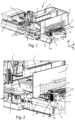
figure 1 is an overall axonometric view of a machine tool according to an embodiment of the present invention; -
figure 2 is a detailed isometric view taken fromfigure 1 ; -
figure 3 shows a detail offigure 2 ; -
figure 4 is an isometric view of a component of the machine tool shown infigure 1 , during a step of cleaning a tool; -
figure 5 is a detailed axonometric view relating to a variant of the machine tool shown infigure 1 ; and -
figure 6 shows a detail offigure 5 . - In the various figures, the similar parts will be indicated with the same numerical references.
- With reference to
figures 1-4 , thenumber 1 indicates a machine tool (in particular, a machining center), according to an embodiment of the present invention, for working panels or other pieces of wood or other material. - This
machine tool 1 comprises abase 2, on which a work surface 3 is defined, on which one or more panels or other pieces to be worked are placed and fixed. - The
same machine tool 1 also comprises aportal 4 arranged above the work surface 3 and connected to thebase 2 in a movable manner according to a first axis X. - This
portal 4 can assume, for example, an inverted "U" or "L" upside down shape. - An
operating head 5 is mounted on one side of theportal 4 in a movable way along a second axis Y, substantially orthogonal to the first axis X. - The
operating head 5 can, in turn, move at least along a third axis Z (vertical) substantially orthogonal to the first axis X and second axis Y. - According to further variants, the same operating
head 5 can rotate around one, two, three, or more rotation axes. - Alternatively, or in addition to the possibility of moving the
operating head 5 along said first axis X, moving means (for example, a conveyor belt) can be provided in themachine tool 1 to move said one or more panels or other pieces along said first axis X. - However, in general, in the
machine tool 1 movement means are provided for carrying out a relative movement along the first axis X between said one or more panels, or other workpieces, and theoperating head 5. - The
operating head 5 comprises, in turn, a spindle (not shown) rotatable around its rotation axis and adapted to receive a tool for carrying out one or more machining operations on the workpiece arranged on the work surface 3. - The aforementioned spindle includes one or more bearings.
- A sort of safety guard or a
safety structure 6 arranged around theportal 4, can also be provided in themachine tool 1, in such a way as to offer a cover on at least three sides, and it is movable integrally with theportal 4 itself. - The
machine tool 1 also includes atool storage unit 7 for housing one or more tools, connected integrally to theportal 4, for example at the external side of an upright of theportal 4. - According to further construction variants (not shown), such
tool storage unit 7 can be fixed to thebase 2, in a fixed position with respect to theportal 4. - The
storage unit 7, in turn, comprises a chain, on which a plurality of grippingmembers 8 are mounted, each configured to receive a tool. - The aforesaid chain is movable in such a way as to be able to slide on itself, thus allowing each gripping
member 8 to be positioned on the side of thetool magazine 7, which faces theoperating head 5 to facilitate the removal of a tool from thetool magazine 7 to be part of theoperating head 5 and the positioning of a tool by theoperating head 5 in a grippingmember 8 close to the latter. - According to further constructive variants (not shown), however falling within the scope of the present invention, this
tool magazine 7 can have a different structure and/or shape with respect to those shown in the attached figures. - In the
machine tool 1 there is also a cleaning and/orlubrication station 9 to allow the execution of cleaning and/or lubrication operations on the spindle of theoperating head 5, and on the attachment portions (normally, conical attachments) of the tools. - In the embodiment of the invention shown in
figures 1-4 , the cleaning and/orlubrication station 9 is integrally connected to thebase 2 at one side of the latter, in a position such as not to interfere with the movement of the movable parts of themachine tool 1, such as, for example, thesafety structure 6. - Specifically, the cleaning and/or
lubrication station 9 comprises a casing, or acontainment structure 10, in which achamber 11 communicating with the outside through anopening 12 is defined. - In the cleaning and/or
lubrication station 9 there is also provided a plurality ofbrushes 13, which face towards theaforementioned chamber 11. - The brushes of this plurality of
brushes 13 can be fixed or movable, for example each brush can be rotated on itself by means of motor means suitable for the purpose. - The cleaning and/or
lubrication station 9 also includes one or more cleaningnozzles 14a, fixed or mobile, for the delivery of cleaning substances (for example, compressed air or acetone) and one ormore lubrication nozzles 14b, fixed or mobile, for dispensing lubricants (for example, grease for lubrication). - Said one or more cleaning
nozzles 14a and said one ormore lubrication nozzles 14b are connected to devices for feeding the substances indicated above, and arranged in thechamber 11, so as to direct these substances towards a tool or a spindle arranged in saidchamber 11. - One or more gripping members or elements can be provided in the
chamber 11, such as for example arecess 15 formed in the top part of thecontainment structure 10 in a position adjacent to theopening 12, to grip one or more tools in a removable way so that the latter are, entirely or almost completely, arranged in thesame chamber 11. - If it is necessary to clean and/or lubricate a
tool 16 supplied with themachine tool 1, theoperating head 5, carrying thistool 16 in the relative spindle, approaches the cleaning and/orlubrication station 9, to place saidtool 16 in thechamber 11 making it pass through theopening 12 and placing a portion of it in therecess 15 to hold it in place. - Once the
tool 16 has been placed in thechamber 11 of the cleaning and/orlubrication station 9, thesame tool 16 is subjected to cleaning, by means of the plurality ofbrushes 13 and/or by activating thecleaning nozzles 14a to deliver cleaning substances, and/or lubrication by activating thelubrication nozzles 14b used for dispensing lubricating substances. - The provision of the
recess 15 or of other gripping members entails, as an important advantage, the possibility of cleaning and/or lubricating the tool in the "masked time", namely, while theoperating head 5 is engaged in performing a machining on the workpiece placed on the work surface 3. - Alternatively, if neither the
recess 15 nor other types of gripping members are provided, the above-mentioned cleaning and/or lubrication steps are carried out while thetool 16 is mounted on the spindle of thehead operating head 5 and maintained by the latter in thechamber 11. - If, on the other hand, the need arises to clean and/or lubricate the spindle of the
operating head 5 or a part of it (for example the spindle bearings), theoperating head 5 approaches the cleaning and/orlubrication station 9 in such a way as to arrange the relative spindle inside thechamber 11, making it pass through theopening 12. - While the spindle is kept in the
chamber 11 by operatinghead 5, the same spindle is subjected to a cleaning, by means of the plurality ofbrushes 13 and/or by activating thecleaning nozzles 14a for the delivery of cleaning substances, and/or to a lubrication by activating thelubrication nozzles 14b used for supplying of the lubricating substances. - The cleaning substances and lubricating substances, used for carrying out the cleaning and lubrication operations described above, are prevented from spreading outwards thanks to the shield action carried out by the containment structure itself 10.
- In
figures 5-6 , instead, a variant of themachine tool 1 described above is shown, incorporating a cleaning and/or lubrication station 9' equal to the cleaning and/orlubrication station 9 described above and also provided with a hooking element 17' in the relative top area, configured to engage, in a removable way, to agripping member 8' of the relative storage unit 7'. - In this technical variant, therefore, unlike what has been described above for the
machine tool 1, the cleaning and/or lubrication station 9' is not fixed with respect to the base 2', but it is movable due to the possibility of movement of the grippingmembers 8 themselves of the storage unit 7'. - The operations for cleaning and lubricating the tools and the spindle of the operating head 5' are carried out according to the same methods described above, in relation to the
machine tool 1. - As can be easily inferred from the above description, the machine tool according to the present invention is structured in such a way as to allow cleaning and lubrication operations to be carried out easily and effectively on the spindles of the operating heads and on the tools, preventing them from being damaged, broken, or otherwise unusable.
- The present invention has been described for illustrative but not limitative purposes, according to its preferred embodiments, but it is to be understood that modifications and/or changes can be introduced by those skilled in the art without departing from the relevant scope as defined in the enclosed claims.
Claims (13)
- Machine tool (1) for machining panels or other pieces made of wood or plastic or metal or glass or another material or combinations of materials, comprising:a work surface (3) to support, in use, at least one panel or other piece; andat least one operating device (5, 5') movable at least along a second axis (Y) and along a third axis (Z) and comprising at least one spindle to which can be coupled, in use, in a removable fashion, at least one tool (16); wherein said at least one operating device (5, 5') and said at least one panel or other piece are relatively movable along a first axis (X), wherein said first axis (X), said second axis (Y) and said third axis (Z) are substantially orthogonal to each other;characterised in that it also comprises a cleaning and/or lubrication station (9, 9') comprising at least one cleaning unit (13, 14a), to clean at least a part of said at least one tool (16) and/or at least one part of said at least one spindle, and at least one lubrication unit (14b) for lubricating at least a part of said at least one tool (16) and/or at least a part of said at least one spindle.
- Machine tool (1) according to claim 1, characterised in that said at least one operating device (5, 5') is movable along said first axis (X).
- Machine tool (1) according to claim 1 or 2, characterised in that said at least one operating device (5, 5') is rotatable about at least one axis of rotation.
- Machine tool (1) according to any one of the preceding claims, characterised in that said at least one cleaning unit comprises at least one brush (13) and/or at least one dispensing unit (14a) for delivering compressed air or acetone or other cleaning substances.
- Machine tool (1) according to any one of the preceding claims, characterised in that said at least one lubrication unit comprises at least one dispensing unit (14b) for dispensing lubricating grease or other lubricating substances.
- Machine tool (1) according to any one of the preceding claims, characterised in that said at least one tool (16) comprises a connecting element and in that said at least one spindle comprises a connecting portion configured to couple, in use, in a removable fashion, to said connecting element of said at least one tool (16).
- Machine tool (1) according to any one of the preceding claims, characterised in that said cleaning and/or lubrication station (9, 9') comprises at least one gripping unit (15) to allow the gripping of said at least one tool (16).
- Machine tool (1) according to any one of the preceding claims, characterised in that said cleaning and/or lubrication station (9, 9') comprises a chamber (11) for receiving said at least one tool (16) when the operations are performed for cleaning and/or lubricating at least a part of said at least one tool (16) and/or of said at least one spindle.
- Machine tool (1) according to claims 7 and 8, characterised in that said at least one gripping unit (15) is provided in said chamber (11), to keep said at least one tool (16) in said chamber (11) during the operations for cleaning and/or lubricating at least a part of said at least one tool (16) and/or of said at least one spindle.
- Machine tool (1) according to any one of the preceding claims, characterised in that said at least one spindle comprises at least one bearing and in that said at least one lubrication unit (14b) is configured to lubricate said at least one bearing when said spindle is arranged, at least partially, in said cleaning and/or lubrication station (9, 9').
- Machine tool (1) according to any one of the preceding claims, characterised in that said cleaning and/or lubrication station (9) is in a fixed position with respect to said work surface (3).
- Machine tool (1) according to any one of the preceding claims, characterised in that it comprises at least one tool storage unit (7, 7') for housing a plurality of tools.
- Machine tool (1) according to claim 12 and any one of claims 1 to 10, characterised in that said cleaning and/or lubrication station (9') can be connected, in a removable fashion, to said at least one tool storage unit (7') in such a way that said cleaning and/or lubrication station (9') is movable with respect to said work surface.
Applications Claiming Priority (1)
| Application Number | Priority Date | Filing Date | Title |
|---|---|---|---|
| IT102021000026237A IT202100026237A1 (en) | 2021-10-13 | 2021-10-13 | MACHINE TOOL WITH CLEANING AND LUBRICATION STATION |
Publications (1)
| Publication Number | Publication Date |
|---|---|
| EP4166293A1 true EP4166293A1 (en) | 2023-04-19 |
Family
ID=79601959
Family Applications (1)
| Application Number | Title | Priority Date | Filing Date |
|---|---|---|---|
| EP22197151.8A Pending EP4166293A1 (en) | 2021-10-13 | 2022-09-22 | Machine tool provided with a cleaning and lubrication station |
Country Status (2)
| Country | Link |
|---|---|
| EP (1) | EP4166293A1 (en) |
| IT (1) | IT202100026237A1 (en) |
Citations (12)
| Publication number | Priority date | Publication date | Assignee | Title |
|---|---|---|---|---|
| JPH05169345A (en) * | 1991-12-18 | 1993-07-09 | Hitachi Ltd | Machining unit |
| JPH07276184A (en) * | 1994-04-05 | 1995-10-24 | Toshiba Corp | Cooling liquid supply device and supply method |
| GB2312501A (en) * | 1996-03-28 | 1997-10-29 | Nippon Mektron Kk | Preventing adhesion of chips to drill shank |
| JP2005052948A (en) * | 2003-08-06 | 2005-03-03 | Fanuc Ltd | Tool changer and tool cleaning method |
| JP2007175786A (en) * | 2005-12-26 | 2007-07-12 | Brother Ind Ltd | Tool cleaning mechanism and tool cleaning method |
| EP2153952A1 (en) * | 2008-08-11 | 2010-02-17 | Homag Holzbearbeitungssysteme AG | Processing device |
| ITMO20100054A1 (en) * | 2010-03-05 | 2011-09-06 | Tecnema Societa A Responsabilita Limitata | CUTTING MACHINE FOR LASTRIFORMS, PARTICULARLY FOR CUTTING CERAMIC TILES, NATURAL AND SIMILAR STONES |
| WO2012011058A1 (en) * | 2010-07-21 | 2012-01-26 | Giuseppe Balotelli | Tool-holding device |
| JP5424029B2 (en) * | 2009-08-26 | 2014-02-26 | 豊和工業株式会社 | Horizontal machining center |
| CN106217498A (en) * | 2016-08-30 | 2016-12-14 | 武侯区华聚家私经营部 | A kind of top-grade furniture carpenter's drilling machine for machining |
| IT201600103949A1 (en) * | 2016-10-17 | 2018-04-17 | Bre Ma Brenna Macch S R L | MACHINE FOR PROCESSING PLASTIC OR SIMILAR MATERIAL SHEETS |
| JP2021000703A (en) * | 2019-06-24 | 2021-01-07 | ファナック株式会社 | Tool washing apparatus, machine tool and tool washing method |
-
2021
- 2021-10-13 IT IT102021000026237A patent/IT202100026237A1/en unknown
-
2022
- 2022-09-22 EP EP22197151.8A patent/EP4166293A1/en active Pending
Patent Citations (12)
| Publication number | Priority date | Publication date | Assignee | Title |
|---|---|---|---|---|
| JPH05169345A (en) * | 1991-12-18 | 1993-07-09 | Hitachi Ltd | Machining unit |
| JPH07276184A (en) * | 1994-04-05 | 1995-10-24 | Toshiba Corp | Cooling liquid supply device and supply method |
| GB2312501A (en) * | 1996-03-28 | 1997-10-29 | Nippon Mektron Kk | Preventing adhesion of chips to drill shank |
| JP2005052948A (en) * | 2003-08-06 | 2005-03-03 | Fanuc Ltd | Tool changer and tool cleaning method |
| JP2007175786A (en) * | 2005-12-26 | 2007-07-12 | Brother Ind Ltd | Tool cleaning mechanism and tool cleaning method |
| EP2153952A1 (en) * | 2008-08-11 | 2010-02-17 | Homag Holzbearbeitungssysteme AG | Processing device |
| JP5424029B2 (en) * | 2009-08-26 | 2014-02-26 | 豊和工業株式会社 | Horizontal machining center |
| ITMO20100054A1 (en) * | 2010-03-05 | 2011-09-06 | Tecnema Societa A Responsabilita Limitata | CUTTING MACHINE FOR LASTRIFORMS, PARTICULARLY FOR CUTTING CERAMIC TILES, NATURAL AND SIMILAR STONES |
| WO2012011058A1 (en) * | 2010-07-21 | 2012-01-26 | Giuseppe Balotelli | Tool-holding device |
| CN106217498A (en) * | 2016-08-30 | 2016-12-14 | 武侯区华聚家私经营部 | A kind of top-grade furniture carpenter's drilling machine for machining |
| IT201600103949A1 (en) * | 2016-10-17 | 2018-04-17 | Bre Ma Brenna Macch S R L | MACHINE FOR PROCESSING PLASTIC OR SIMILAR MATERIAL SHEETS |
| JP2021000703A (en) * | 2019-06-24 | 2021-01-07 | ファナック株式会社 | Tool washing apparatus, machine tool and tool washing method |
Also Published As
| Publication number | Publication date |
|---|---|
| IT202100026237A1 (en) | 2023-04-13 |
Similar Documents
| Publication | Publication Date | Title |
|---|---|---|
| US5564483A (en) | Unit for machining workpieces, in particular wood | |
| US7357769B2 (en) | Machine tool | |
| US6745455B2 (en) | Automatic milling and drilling machine | |
| US7044693B2 (en) | Machine tool | |
| US4563115A (en) | Cutting machine having stock suction means | |
| EP3391994A1 (en) | Wire saw device, and processing method and processing device for workpiece | |
| JPH08215960A (en) | Machine tools for drilling and milling | |
| JPH08215961A (en) | Machine tools for drilling and milling | |
| US11524378B2 (en) | Dust collection deburring apparatus | |
| KR100890990B1 (en) | CNC High Speed Processor with Dust Collector for Chip Removal | |
| JP2017013130A (en) | Nozzle exchanger and laser processing machine with nozzle exchanger | |
| KR100829043B1 (en) | Surface Polishing Machine of Workpiece | |
| CA1220928A (en) | Machine tool | |
| KR200497149Y1 (en) | Machine tool with the air injector unit of removing cutting oil | |
| KR102625560B1 (en) | Top surface cutting machine | |
| CN220094279U (en) | Workpiece fixed-point rotary sand blasting and shot blasting machine | |
| JPH06246627A (en) | Grinding treatment device | |
| IT202100026237A1 (en) | MACHINE TOOL WITH CLEANING AND LUBRICATION STATION | |
| JP2022178891A (en) | Auxiliary device | |
| JP2001121301A (en) | Spindle movable vertical machine tool | |
| KR102324555B1 (en) | Bed of a machine tool and bed assembly including the same | |
| KR20220076275A (en) | Automatic processing apparatus | |
| CN114536114A (en) | Multi-shaft linkage special tool grinding machine | |
| JP7108111B1 (en) | Tool magazine device | |
| JP7021252B2 (en) | Cleaning lid member and work cleaning method |
Legal Events
| Date | Code | Title | Description |
|---|---|---|---|
| PUAI | Public reference made under article 153(3) epc to a published international application that has entered the european phase |
Free format text: ORIGINAL CODE: 0009012 |
|
| STAA | Information on the status of an ep patent application or granted ep patent |
Free format text: STATUS: THE APPLICATION HAS BEEN PUBLISHED |
|
| AK | Designated contracting states |
Kind code of ref document: A1 Designated state(s): AL AT BE BG CH CY CZ DE DK EE ES FI FR GB GR HR HU IE IS IT LI LT LU LV MC MK MT NL NO PL PT RO RS SE SI SK SM TR |
|
| P01 | Opt-out of the competence of the unified patent court (upc) registered |
Effective date: 20230518 |
|
| STAA | Information on the status of an ep patent application or granted ep patent |
Free format text: STATUS: REQUEST FOR EXAMINATION WAS MADE |
|
| 17P | Request for examination filed |
Effective date: 20230925 |
|
| RBV | Designated contracting states (corrected) |
Designated state(s): AL AT BE BG CH CY CZ DE DK EE ES FI FR GB GR HR HU IE IS IT LI LT LU LV MC MK MT NL NO PL PT RO RS SE SI SK SM TR |
|
| STAA | Information on the status of an ep patent application or granted ep patent |
Free format text: STATUS: EXAMINATION IS IN PROGRESS |
|
| 17Q | First examination report despatched |
Effective date: 20260310 |