EP4166285A1 - Greifvorrichtung - Google Patents
Greifvorrichtung Download PDFInfo
- Publication number
- EP4166285A1 EP4166285A1 EP22199042.7A EP22199042A EP4166285A1 EP 4166285 A1 EP4166285 A1 EP 4166285A1 EP 22199042 A EP22199042 A EP 22199042A EP 4166285 A1 EP4166285 A1 EP 4166285A1
- Authority
- EP
- European Patent Office
- Prior art keywords
- gripper
- particle
- phase change
- surface membrane
- flexible surface
- Prior art date
- Legal status (The legal status is an assumption and is not a legal conclusion. Google has not performed a legal analysis and makes no representation as to the accuracy of the status listed.)
- Withdrawn
Links
Images

Classifications
-
- B—PERFORMING OPERATIONS; TRANSPORTING
- B25—HAND TOOLS; PORTABLE POWER-DRIVEN TOOLS; MANIPULATORS
- B25J—MANIPULATORS; CHAMBERS PROVIDED WITH MANIPULATION DEVICES
- B25J15/00—Gripping heads and other end effectors
- B25J15/06—Gripping heads and other end effectors with vacuum or magnetic holding means
- B25J15/0616—Gripping heads and other end effectors with vacuum or magnetic holding means with vacuum
- B25J15/0625—Gripping heads and other end effectors with vacuum or magnetic holding means with vacuum provided with a valve
- B25J15/0633—Air-flow-actuated valves
-
- B—PERFORMING OPERATIONS; TRANSPORTING
- B25—HAND TOOLS; PORTABLE POWER-DRIVEN TOOLS; MANIPULATORS
- B25J—MANIPULATORS; CHAMBERS PROVIDED WITH MANIPULATION DEVICES
- B25J15/00—Gripping heads and other end effectors
- B25J15/0023—Gripper surfaces directly activated by a fluid
-
- B—PERFORMING OPERATIONS; TRANSPORTING
- B25—HAND TOOLS; PORTABLE POWER-DRIVEN TOOLS; MANIPULATORS
- B25J—MANIPULATORS; CHAMBERS PROVIDED WITH MANIPULATION DEVICES
- B25J15/00—Gripping heads and other end effectors
- B25J15/06—Gripping heads and other end effectors with vacuum or magnetic holding means
- B25J15/0608—Gripping heads and other end effectors with vacuum or magnetic holding means with magnetic holding means
-
- B—PERFORMING OPERATIONS; TRANSPORTING
- B25—HAND TOOLS; PORTABLE POWER-DRIVEN TOOLS; MANIPULATORS
- B25J—MANIPULATORS; CHAMBERS PROVIDED WITH MANIPULATION DEVICES
- B25J9/00—Program-controlled manipulators
- B25J9/06—Program-controlled manipulators characterised by multi-articulated arms
- B25J9/065—Snake robots
Definitions
- the present disclosure concerns a gripper device.
- the invention relates to a soft gripper for use on a robotic arm.
- Pipelines and other confined spaces can become contaminated by particles or debris that have either entered the system from an external source or become detached from the system.
- the gripping of particles or debris in difficult to reach areas is often performed by a robotic arm. Attached to the end of the robotic arm is a hand-like gripper. However, if these grippers hit the side of a fragile component, they can result in more damage than would have been caused by the object if it had been left in situ. As such, there is a need for softer grippers to be developed that can be attached to the robotic arms.
- Non-robotic grippers are also known. There are examples of these having a deformable head as shown in WO 2015/006613 A1 . However, this deformable head is still connected to a rigid base body portion, which connects it to the arm. The presence of this rigid base body portion on the tool can have a similar effect to the hand of the robotic gripper if it contacts a delicate surface.
- a particle gripper comprising:
- the particle gripper may be connected to a robotic arm.
- the robotic arm may be a continuum robotic arm or a snake arm robotic arm.
- the resiliently deformable neck portion may be made of silicone.
- a clamp may be attached to the resiliently deformable neck portion.
- the clamp may be connected to a rod along which the at least one air tube runs.
- the resiliently deformable neck portion may extend in a plane along the length of the air tube such that the flexible surface membrane expands in a direction perpendicular to the length of the air tube.
- the flexible surface membrane may be made from rubber like material such as rubber, silicone or latex.
- the phase change material may be a granular material, which becomes solid under a vacuum transition.
- the phase change material may be a ferromagnetic fluid that undergoes a phase transition under the application of a current transition means.
- the transitioning means may comprise applying a vacuum to the phase transition material in order to induce the phase transition.
- the transitioning means may comprise applying an electric current to the phase transition material in order to induce the phase transition.
- FIG 1 presents a first embodiment of a gripper of the present disclosure.
- the gripper is shown being attached to an extendible arm.
- a vertical gripper head 10 is mounted via a clamp 12 onto the extendible arm 14.
- the term vertical is denotes when the deformable surface extends in the same plane as the arm to which it is attached, whilst the term horizontal is used to refer to the deformable surface extending perpendicular to the plane of the arm.
- the vertical gripper head 10 comprises a rigid neck portion (22 in figure 2 ) which is connected to the arm 14, and a deformable front surface (24 in figure 2 ).
- the deformable front surface is able to deform in the presence of an object to be gripped. Between the rigid neck and the deformable front surface is an internal cavity.
- the material inside the cavity may be a granular phase change material which is able to flow around the object being gripped by the surface layer and then changes phase to become a solid so that the object is firmly gripped and so that it can be removed.
- An air hose 16 is supplied to the gripper head 10; this allows the gripper head to have a vacuum created within it or air blown into it to remove the vacuum. The use of a vacuum allows the granular phase transition material to change from a fluid into a solid.
- the arm presented in Figure 1 is rigid, it could be attached to any suitable length of pole. Alternatively, it could also be attached to any suitable arm or robotic arm.
- the gripper could be mounted to a snake arm or continuum arm robot.
- the air tube and/or electrical cables may be run through the central section of the robotic arm.
- the use of a continuum arm robot allows the gripper to be manipulated in three dimensions. Consequently, the gripper can be manipulated to be positioned at any location in pipework or within a machine that is not easily accessible through normal means.
- the gripper comprises a neck portion 22, which has a hollow cavity 23.
- the neck portion is made of a resiliently deformable material.
- the neck portion may be made from a silicone material or any other suitable material having similar properties.
- the neck portion may be made from a rigid material. The construction of the neck portion will depend on the delicacy of the system into which the gripper is to be applied.
- the neck portion may be made from rubber or plastic like materials.
- the flexible membrane may be made from a rubber like material such as rubber, silicone or latex.
- the membrane surface needs to be made of a material that is tough enough that it will not break or rip if it touches the side of a sharp object that is to be gripped, but still needs to be flexible enough to be able to deform around the object.
- the cavity within the neck portion is filled with a phase transition material.
- the phase transition material may be a granular material that changes from a fluid to a solid under the application of a vacuum, this phenomenon is known as particle jamming.
- the phase transition material may be a ferromagnetic fluid which changes from a fluid to a solid through the application of a current.
- the neck portion also features an air tube that allow air supply to be moderated into the neck section. This allows for the phase change material to be moved within the cavity and allows it to expand into the flexible membrane. This movement causes the outside of the surface membrane to expand until it contacts an object to be gripped. At this point it is able to deform around the object, the material can then undergo a phase transition and the object will be securely gripped by the gripper.
- a vertical gripper is useful for directly gripping objects that are directly in front of the gripper.
- the head of a vertical gripper cannot be contorted to be able to grip particles at the side of the pipe. Consequently, in such confined spaces a vertical head gripper cannot be used.
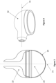
- a gripper is shown for use in such constricted spaces.
- the neck portion 32 is in a horizontal configuration.
- the flexible membrane is able to expand in an axis that is perpendicular to the axis of the length of the robotic arm 31. This configuration allows the gripper to grab objects that are at the side of a pipe and the head does not need to be contorted to grip an object at the side of the pipe.
- the remaining construction of the gripper portion is identical to that of the vertical gripper.
- the horizontal gripper may be connected to a suitable rotation means, such that the gripper can be rotated through 360° around the axis of the arm. This allows the gripper to be rotated to any position so that it can pick up debris at any position within a cylinder or a pipe.
- the use of a resiliently deformable material for the neck portion means that the neck portion can be rested against the side of a pipe without the risk of damaging the cylinder or pipe. Furthermore, it also reduces the chance of damage to the flexible membrane from any rough sides of pipe of cylinder. Once the object has been picked up, the gripper can be rotated back to a neutral position in order for the object to be extracted.
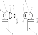
- Figure 4a and 4b display the gripper of Figure 3 in use.
- the gripper is in the horizontal configuration as shown in Figure 3 .
- the gripper 41 is connected to a robotic arm 42.
- the gripper is in the pre gripping state with the phase transition in its fluid state.
- the flexible membrane has the fluid near to the surface, so that the flexible membrane is expanded and is in its gripping configuration.
- the gripper can be rotated so that the flexible membrane is pointing towards the object 43 that is to be picked up.
- the resiliently deformable neck portion 44 faces in the opposite direction, so that it can protect the flexible membrane against any rough surface in the space where there is the object to be picked up.
- the neck may rest against the wall of the pipe or space. Therefore, the presence of the resiliently deformable neck increases the resilience of the gripper, which will in turn increase the lifespan of the gripper.
- the gripper With the gripper in this orientation the gripper can then be moved onto the object. As the gripper moves over the object the flexible membrane 45 deforms along with the phase transition fluid that is positioned behind the flexible membrane. This movement of the phase transition fluid and the flexible membrane allows the object to be surrounded by the membrane and encased by the phase transition fluid. The phase transition fluid can then undergo the phase transition from a fluid to a solid. Consequently, the object can then be held in the gripper as the phase transition fluid is now solid.
- the gripper can then be rotated and removed from the space so that the object can be collected.
- the gripper head may be equipped with at least one camera so that the positioning of the head can be controlled. In this the at least one camera allows the operator to see the positioning of the head and then controlling the gripper around the object to be gripped.
- an imaging system may be the use of a fibreoptic imaging system that can provide a real time view of the position of the head of the gripper to an operator.
- Such a device is useful in the removal of foreign materials that have the potential to cause mechanical damage. Also, due to the soft fluidic head it is suitable to grip objects of a large range of geometries. The device may also be suitable for use in gas turbine engines. Alternatively, the device may be used in other industrial applications in which access is restricted, such as chemical plants or within complex objects such as gas turbine engines or in pipe networks.
- the use of the gripper head in its particular location will determine the size of the gripper that is used. It will also determine what arm it can be attached. The size of the gripper head may be of any suitable size.
Landscapes
- Engineering & Computer Science (AREA)
- Robotics (AREA)
- Mechanical Engineering (AREA)
- Manipulator (AREA)
Applications Claiming Priority (1)
| Application Number | Priority Date | Filing Date | Title |
|---|---|---|---|
| GBGB2114779.8A GB202114779D0 (en) | 2021-10-15 | 2021-10-15 | Gripper device |
Publications (1)
| Publication Number | Publication Date |
|---|---|
| EP4166285A1 true EP4166285A1 (de) | 2023-04-19 |
Family
ID=78718378
Family Applications (1)
| Application Number | Title | Priority Date | Filing Date |
|---|---|---|---|
| EP22199042.7A Withdrawn EP4166285A1 (de) | 2021-10-15 | 2022-09-30 | Greifvorrichtung |
Country Status (3)
| Country | Link |
|---|---|
| US (1) | US20230124447A1 (de) |
| EP (1) | EP4166285A1 (de) |
| GB (1) | GB202114779D0 (de) |
Citations (8)
| Publication number | Priority date | Publication date | Assignee | Title |
|---|---|---|---|---|
| US4561686A (en) * | 1983-08-22 | 1985-12-31 | Raymond Atchley | End effector |
| JP2013220508A (ja) * | 2012-04-17 | 2013-10-28 | Ihi Corp | 汎用ロボットハンド |
| WO2015006613A1 (en) | 2013-07-10 | 2015-01-15 | Empire Robotics, Inc. | End effector, apparatus, system and method for gripping and releasing articles and the like |
| JP2016112664A (ja) * | 2014-12-17 | 2016-06-23 | 豊田合成株式会社 | 物品把持具 |
| DE102016201541A1 (de) * | 2016-02-02 | 2017-08-03 | Deutsches Zentrum für Luft- und Raumfahrt e.V. | Robotischer Greifer sowie Verfahren zum Betreiben eines solchen |
| US20190217485A1 (en) * | 2017-03-13 | 2019-07-18 | Kabushiki Kaisha Toshiba | Gripping tool, gripping system, and evaluation method of gripping performance |
| US20200215701A1 (en) * | 2017-09-26 | 2020-07-09 | Kabushiki Kaisha Toshiba | Gripping tool, gripping system, and method for manufacturing resin member |
| US20210122063A1 (en) * | 2019-10-24 | 2021-04-29 | Tohoku University | Suction gripper |
Family Cites Families (3)
| Publication number | Priority date | Publication date | Assignee | Title |
|---|---|---|---|---|
| US20160052145A1 (en) * | 2014-08-19 | 2016-02-25 | GM Global Technology Operations LLC | Conformable holding device |
| GB2560355A (en) * | 2017-03-09 | 2018-09-12 | Rolls Royce Plc | Apparatus and methods for enabling determination of a shape of at least a portion of a continuum robot |
| US10661446B2 (en) * | 2018-04-06 | 2020-05-26 | Aurora Flight Sciences Corporation | Jamming grippers with stencil moldings |
-
2021
- 2021-10-15 GB GBGB2114779.8A patent/GB202114779D0/en not_active Ceased
-
2022
- 2022-09-30 EP EP22199042.7A patent/EP4166285A1/de not_active Withdrawn
- 2022-10-04 US US17/959,533 patent/US20230124447A1/en active Pending
Patent Citations (8)
| Publication number | Priority date | Publication date | Assignee | Title |
|---|---|---|---|---|
| US4561686A (en) * | 1983-08-22 | 1985-12-31 | Raymond Atchley | End effector |
| JP2013220508A (ja) * | 2012-04-17 | 2013-10-28 | Ihi Corp | 汎用ロボットハンド |
| WO2015006613A1 (en) | 2013-07-10 | 2015-01-15 | Empire Robotics, Inc. | End effector, apparatus, system and method for gripping and releasing articles and the like |
| JP2016112664A (ja) * | 2014-12-17 | 2016-06-23 | 豊田合成株式会社 | 物品把持具 |
| DE102016201541A1 (de) * | 2016-02-02 | 2017-08-03 | Deutsches Zentrum für Luft- und Raumfahrt e.V. | Robotischer Greifer sowie Verfahren zum Betreiben eines solchen |
| US20190217485A1 (en) * | 2017-03-13 | 2019-07-18 | Kabushiki Kaisha Toshiba | Gripping tool, gripping system, and evaluation method of gripping performance |
| US20200215701A1 (en) * | 2017-09-26 | 2020-07-09 | Kabushiki Kaisha Toshiba | Gripping tool, gripping system, and method for manufacturing resin member |
| US20210122063A1 (en) * | 2019-10-24 | 2021-04-29 | Tohoku University | Suction gripper |
Also Published As
| Publication number | Publication date |
|---|---|
| GB202114779D0 (en) | 2021-12-01 |
| US20230124447A1 (en) | 2023-04-20 |
Similar Documents
| Publication | Publication Date | Title |
|---|---|---|
| US12145269B2 (en) | System and method for robotic gripping utilizing dynamic collision modeling for vacuum suction and finger control | |
| CN108495738B (zh) | 用于提供动态机器人控制系统的系统和方法 | |
| CN109716004B (zh) | 协调型水环境移动机器人 | |
| US5090758A (en) | Rigid spine inflatable end effector | |
| CN107921648A (zh) | 用于连接机器人的设备 | |
| JP2011000703A (ja) | カメラ付きマニピュレータ | |
| US11633861B2 (en) | Systems, methods and associated components for robotic manipulation of physical objects | |
| CN109641358B (zh) | 隔离系统 | |
| CN112055922B (zh) | 线缆处理设备及其使用和为其使用做准备的方法 | |
| WO2017085897A1 (ja) | 製造システム、製造システムの構築方法、エンドエフェクタ、ロボット、及びロボットの作業方法 | |
| US11814911B2 (en) | Passive tubular connection guide | |
| CN107471244A (zh) | 一种物流用柔性多指机械手及用其抓取物料的方法 | |
| US20210276641A1 (en) | Tethered Mobile Climbing Robot for Inspecting Tanks in Confined Environments | |
| JP2011173211A (ja) | 多関節ロボットの駆動制御方法及び多関節ロボットの配線配管保護装置 | |
| EP4166285A1 (de) | Greifvorrichtung | |
| CN108161940B (zh) | 利用空间机械手操作系统实现人机协同拧松螺钉操作方法 | |
| CN207172109U (zh) | 一种物流用柔性多指机械手 | |
| US12251832B2 (en) | Robot stiffness | |
| Yong et al. | Design and modeling of a nested bi-cavity-based soft growing robot for grasping in constrained environments | |
| US11745357B2 (en) | Robotic arm and robot having the same | |
| CN109760105A (zh) | 机器人 | |
| EP4252978B1 (de) | Gelenkmanipulator zum navigieren und warten eines wärmetauschers | |
| KR20200078114A (ko) | 탈부착이 용이한 드론 장착용 로봇 팔 | |
| US11964388B2 (en) | Continuum arm robot | |
| CN204010705U (zh) | 一种核电站水下带吸盘的浮游装置 |
Legal Events
| Date | Code | Title | Description |
|---|---|---|---|
| PUAI | Public reference made under article 153(3) epc to a published international application that has entered the european phase |
Free format text: ORIGINAL CODE: 0009012 |
|
| STAA | Information on the status of an ep patent application or granted ep patent |
Free format text: STATUS: THE APPLICATION HAS BEEN PUBLISHED |
|
| AK | Designated contracting states |
Kind code of ref document: A1 Designated state(s): AL AT BE BG CH CY CZ DE DK EE ES FI FR GB GR HR HU IE IS IT LI LT LU LV MC MK MT NL NO PL PT RO RS SE SI SK SM TR |
|
| STAA | Information on the status of an ep patent application or granted ep patent |
Free format text: STATUS: REQUEST FOR EXAMINATION WAS MADE |
|
| 17P | Request for examination filed |
Effective date: 20230927 |
|
| RBV | Designated contracting states (corrected) |
Designated state(s): AL AT BE BG CH CY CZ DE DK EE ES FI FR GB GR HR HU IE IS IT LI LT LU LV MC MK MT NL NO PL PT RO RS SE SI SK SM TR |
|
| STAA | Information on the status of an ep patent application or granted ep patent |
Free format text: STATUS: EXAMINATION IS IN PROGRESS |
|
| 17Q | First examination report despatched |
Effective date: 20241104 |
|
| STAA | Information on the status of an ep patent application or granted ep patent |
Free format text: STATUS: THE APPLICATION HAS BEEN WITHDRAWN |
|
| 18W | Application withdrawn |
Effective date: 20250108 |