EP4166275B1 - Verfahren zur bestimmung der form einer brillengestelllünette - Google Patents
Verfahren zur bestimmung der form einer brillengestelllünette Download PDFInfo
- Publication number
- EP4166275B1 EP4166275B1 EP21306457.9A EP21306457A EP4166275B1 EP 4166275 B1 EP4166275 B1 EP 4166275B1 EP 21306457 A EP21306457 A EP 21306457A EP 4166275 B1 EP4166275 B1 EP 4166275B1
- Authority
- EP
- European Patent Office
- Prior art keywords
- cross
- section
- bezel
- shape
- felt
- Prior art date
- Legal status (The legal status is an assumption and is not a legal conclusion. Google has not performed a legal analysis and makes no representation as to the accuracy of the status listed.)
- Active
Links
Images


Classifications
-
- G—PHYSICS
- G01—MEASURING; TESTING
- G01B—MEASURING LENGTH, THICKNESS OR SIMILAR LINEAR DIMENSIONS; MEASURING ANGLES; MEASURING AREAS; MEASURING IRREGULARITIES OF SURFACES OR CONTOURS
- G01B5/00—Measuring arrangements characterised by the use of mechanical techniques
- G01B5/20—Measuring arrangements characterised by the use of mechanical techniques for measuring contours or curvatures
-
- B—PERFORMING OPERATIONS; TRANSPORTING
- B24—GRINDING; POLISHING
- B24B—MACHINES, DEVICES, OR PROCESSES FOR GRINDING OR POLISHING; DRESSING OR CONDITIONING OF ABRADING SURFACES; FEEDING OF GRINDING, POLISHING, OR LAPPING AGENTS
- B24B9/00—Machines or devices designed for grinding edges or bevels on work or for removing burrs; Accessories therefor
- B24B9/02—Machines or devices designed for grinding edges or bevels on work or for removing burrs; Accessories therefor characterised by a special design with respect to properties of materials specific to articles to be ground
- B24B9/06—Machines or devices designed for grinding edges or bevels on work or for removing burrs; Accessories therefor characterised by a special design with respect to properties of materials specific to articles to be ground of non-metallic inorganic material, e.g. stone, ceramics, porcelain
- B24B9/08—Machines or devices designed for grinding edges or bevels on work or for removing burrs; Accessories therefor characterised by a special design with respect to properties of materials specific to articles to be ground of non-metallic inorganic material, e.g. stone, ceramics, porcelain of glass
- B24B9/14—Machines or devices designed for grinding edges or bevels on work or for removing burrs; Accessories therefor characterised by a special design with respect to properties of materials specific to articles to be ground of non-metallic inorganic material, e.g. stone, ceramics, porcelain of glass of optical work, e.g. lenses, prisms
- B24B9/144—Machines or devices designed for grinding edges or bevels on work or for removing burrs; Accessories therefor characterised by a special design with respect to properties of materials specific to articles to be ground of non-metallic inorganic material, e.g. stone, ceramics, porcelain of glass of optical work, e.g. lenses, prisms the spectacles being used as a template
-
- B—PERFORMING OPERATIONS; TRANSPORTING
- B24—GRINDING; POLISHING
- B24B—MACHINES, DEVICES, OR PROCESSES FOR GRINDING OR POLISHING; DRESSING OR CONDITIONING OF ABRADING SURFACES; FEEDING OF GRINDING, POLISHING, OR LAPPING AGENTS
- B24B9/00—Machines or devices designed for grinding edges or bevels on work or for removing burrs; Accessories therefor
- B24B9/02—Machines or devices designed for grinding edges or bevels on work or for removing burrs; Accessories therefor characterised by a special design with respect to properties of materials specific to articles to be ground
- B24B9/06—Machines or devices designed for grinding edges or bevels on work or for removing burrs; Accessories therefor characterised by a special design with respect to properties of materials specific to articles to be ground of non-metallic inorganic material, e.g. stone, ceramics, porcelain
- B24B9/08—Machines or devices designed for grinding edges or bevels on work or for removing burrs; Accessories therefor characterised by a special design with respect to properties of materials specific to articles to be ground of non-metallic inorganic material, e.g. stone, ceramics, porcelain of glass
- B24B9/14—Machines or devices designed for grinding edges or bevels on work or for removing burrs; Accessories therefor characterised by a special design with respect to properties of materials specific to articles to be ground of non-metallic inorganic material, e.g. stone, ceramics, porcelain of glass of optical work, e.g. lenses, prisms
- B24B9/148—Machines or devices designed for grinding edges or bevels on work or for removing burrs; Accessories therefor characterised by a special design with respect to properties of materials specific to articles to be ground of non-metallic inorganic material, e.g. stone, ceramics, porcelain of glass of optical work, e.g. lenses, prisms electrically, e.g. numerically, controlled
Definitions
- the present invention relates in general to the field of eyeglass manufacture, and more precisely to machining ophthalmic lenses.
- It relates more particularly to a method for determining the shape of a bezel of an eyeglass frame rim, this operation being the prerequisite for edging a lens to be mounted in said rim.
- the technical part of the work of an optician which consists in mounting a pair of ophthalmic lenses in a spectacle frame selected by a customer, may be split into four main operations:
- the acquisition operation is more particularly of interest.
- This operation is usually carried out by an optician by means of a reader appliance.
- Such a reader appliance usually includes a frame blocking support, a feeler that is movable relative to the support, and an electronic and/or computer unit for controlling the position of the feeler relative to the support.
- the electronic and/or computer unit is thus adapted to acquire the coordinates of a plurality of points that are felt around the bezel of each rim of the frame, and then to deduce therefrom a control setpoint for the machining tool.
- This measure is usually performed at the bottom of the rim because the cross-section of the bevel is easier to feel in this area.
- US 2010/112908 A1 and US 8 132 909 B2 disclose a processes for machining a lens and a method of preparing an ophthalmic lens respectively.
- the present invention provides a method for determining the shape of a bezel of an eyeglass frame rim, as defined in independent claim 1. Preferred embodiments are defined in the dependent claims.
- the invention it is possible, by using a simple feeler device, to determine a better approximation of the 3D-shape of the bezel, by reading the shape of at least the cross-section that is considered as the most characteristic of the bezel shape.
- At least two cross-sections are read.
- the invention enables the user of the shaper device to measure or to approximate the differences in height between the front and rear sides of the bezel at a small number of cross-sections of each rim, so that the engagement bevel can be machined as a function of those height differences.
- This operation can be performed without special tooling and without requiring much time.
- the measurements taken are then input to the shaper device so that it machines the lens bevel with a profile that is not uniform, making it possible to avoid problems of mechanical interference between the lens and the frame.
- the height difference may be measured between the front and rear edges of the bezel, where the rim forms an obstacle (temple, bridge, nose pad). Consequently, because these obstacles often deform the rims, the presence of the obstacle has an effect on the measured height difference. Therefore, by taking this difference into account during the machining of the lens, it is potentially possible to reduce the risk of interference between the lens and the obstacle. This is particularly advantageous since such an interference would deform the frame or create mechanical stress on the lens or even make the mounting of the lens into the rim impossible.
- the process makes sure that the processed lens geometry will not create any deformation of the frame front due to interference between the lens and the rear area.
- the invention also concerns a process for machining a lens to be mounted into an eyeglass frame rim, comprising:
- said bevel comprising a front flank and a rear flank, the height of the front flank being different from the height of the rear flank in said particular cross-section, said difference being determined as a function of the shape of the bezel felt cross-section.
- said edging parameters are such that said particular cross-section of the bevel has a shape depending on one of the following data:
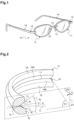
- Figure 1 shows a rimmed eyeglass frame 10 having two rims 11 (or surrounds), each serving to receive an ophthalmic lens and to be positioned in front of a respective one of the two eyes of a wearer when said frame is being worn.
- the two rims 11 are connected together by a bridge 12. They are also each fitted with a nose pad 13 suitable for resting on the wearer's nose and a temple (earpiece) 14 suitable for resting on one of the wearer's ears.
- Each temple 14 is hinged to the corresponding rim by means of a hinge 15.
- each rim 11 of the eyeglass frame 10 presents an inside face including an inside engagement groove, commonly referred to as a bezel 16.
- the bezel 16 presents a V-shaped axial cross-section with front and rear flanks 16A and 16B and a bottom edge 17. It is bordered by front and rear margins 18 and 19.
- the bezel could naturally be of some other shape, for example it could be circularly arcuate.
- the mean plane P1 is defined as the plane that comes closest to the set of points making up the bottom edge 17 of the bezel 16.
- the coordinates of this plane may be obtained, for example, by applying the least squares method to the coordinates of a plurality of points on the bottom of the bezel.
- the mean axis A1 is defined as being the axis normal to the mean plane P1, passing through the barycenter (center of gravity) of the points making up the bottom edge 17 of the bezel 16.
- each rim 11 is defined as being the intersection of the rim 11 with a plane P2 j that contains the mean axis A1 and that presents an angle of orientation ⁇ j around said axis.
- Each cross-section S j defines a rim profile P j .
- Each of these profiles P j in this embodiment comprises two parallel segments corresponding to the traces of the front and rear margins 18 and 19 in the plane P2 j , and two V-shaped segments corresponding to the traces of the front and rear flanks 16A and 16B in the plane P2 j .
- the rim profiles P j are of shapes that can vary around the outline of each rim 11.
- the front and rear margins 18 and 19 present respective first and second distances from the mean axis A1, the difference between these distances referring to as the offset height G j .
- This offset height G j could be defined as the difference between firstly the maximum distance to the mean axis A1 of the trace of the front margin 18 in the cross-section S j under consideration, and secondly the maximum distance to the mean axis A1 of the trace of the rear margin 19 in said cross-section S j .
- this offset height G j is preferably measured not radially relative to the mean axis A1, but along the bisector direction F j .
- the front lens curvature shall be approximately equal to the frame curvature (that is to say parallel to the bisector direction F j ).
- the nose pads 13 and the hinges 15 are fastened to the rear margins 19, their presence may have an influence on the shape of this margin. Therefore, it can be understood that the nose pads 13 and the hinges 15 can have an influence on the offset height G j .
- the opening angle D j of the bezel 16 in each cross-section S j is defined as the angle between the traces of the front and rear flanks 16A and 16B.
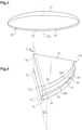
- the eyeglass frame 10 can also be cambered.
- the bezels 16 are thus skewed, i.e. twisted. Consequently, and as shown in Figure 2 , each cross-section S j of the bezel 16 presents its own angle of inclination.
- This angle of inclination, which varies along the bezels 16, is quantified in each cross-section S j in terms of an angle C j referred to the skew angle.
- the skew angle C j corresponds to the angle between the bisector F j of the bezel 16 and an axis perpendicular to the mean axis A1 in the mean plane P1 of the rim 11.
- the ophthalmic lens 20 presents front and rear optical faces 21 and 22, together with an edge face 23.
- the ophthalmic lens 20 presents optical characteristics and geometrical characteristics.
- the spherical refringent power of the lens which is the magnitude that characterizes and quantifies the "magnifying glass" effect of the lens on the beam under consideration.
- the point of the lens where the magnifying glass effect is zero i.e. for a lens that has spherical optical power only, the point where the incident ray and the transmitted ray have the same axis
- the optical center is referred to as the optical center.
- the edge face 23 of the lens initially presents an outline that is circular ( Figure 3 ). Nevertheless, the lens is designed to be shaped to match the shape of the corresponding rim of the eyeglass frame 10, so as to enable it to be engaged therein.
- the lens is more precisely designed to be shaped so as to present on its edge face 23 an engagement ridge 26 (or bevel) bordered by front and rear margins 28 and 29.
- the engagement ridge 26 described herein presents a V-shaped section with a top edge 27 that runs along the edge face 23 of the lens, with front and rear flanks 26A and 26B on either side of the top edge 27.
- the edge face of the ophthalmic lens could be shaped so as to present a profile of some other shape.
- a mean plane and a mean axis A2 can be defined for the lens.
- the mean plane can be defined as the plane orthogonal to the optical axis of the lens.
- the mean axis A2 can be defined as being the axis normal to this mean plane, passing through the barycenter of the points making up the top edge 27 of the bevel 26.
- the axial section S' i of the ophthalmic lens 20 is defined as the intersection of said lens with a half-plane P3 that is defined by the optical axis A2 and that presents an angle of orientation ⁇ ' i about said axis.
- Each axial section S' i of the ophthalmic lens 20 defines a lens profile P' i .
- Each of these profiles P' i in this example comprises two parallel segments corresponding to the traces of the front and rear margins 28 and 29 in the half-plane P3, and two segments in a V-shape corresponding to the traces of the front and rear flanks 26A and 26B in the half-plane P3.
- an axial section S' i of the lens 20 and a cross-sections S j of the frame 10 will be said to "correspond" when the angular positions thereof ⁇ ' i and ⁇ j are equal.
- This shape reader appliance comprises means that are well known to the person skilled in the art and it does not specifically form the subject matter of the invention described.
- a shape reader appliance as described in patent EP 0 750 172 .
- Figure 5 is a general view of the shape reader appliance 100, as it is presented to its user.
- the appliance has a top cover 101 covering all of the appliance with the exception of a central top portion in which an eyeglass frame 10 is placed.
- the shape reader appliance 100 principally serves to read the shape of the bottom edge of the bezel in each rim 11 of the eyeglass frame 10.
- the reader appliance 100 shown in Figure 5 has a set of two jaws 102 with at least one of the jaws 102 being movable relative to the other so that the jaws 102 can be moved towards each other or away from each other in order to form a clamping device.
- Each of the jaws 102 is also provided with two clamps, each made up of two studs 103 that are movable so as to be capable of clamping the eyeglass frame 10 between them in order to prevent it from moving.
- a structure 104 In the space left visible by the central top opening of the cover 101, there can be seen a structure 104.
- a plate (not visible) can be moved in translation on the structure 104 along a transfer axis A3.
- a turntable 105 is pivotally mounted on the plate. The turntable 105 is thus suitable for occupying two positions along the transfer axis A3, namely a first position in which the center of the turntable 105 is disposed between the two pairs of studs 103 holding the right rim of the eyeglass frame 10, and a second position in which the center of the turntable 105 is placed between the two pairs of studs 103 holding the left rim of the eyeglass frame 10.
- the turntable 105 possesses an axis of rotation A4 defined as being the axis normal to the front face of the turntable 105 and passing through its center. It is adapted to pivot about said axis relative to the plate.
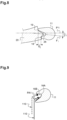
- the turntable 105 also has a circularly arcuate oblong slot 106 through which can move a feeler 110.
- the feeler 110 comprises a support rod 111 of axis perpendicular to the plane of the front face of the turntable 105, and at its free end a feeler finger 112 of axis perpendicular to the support rod 111.
- the feeler finger 112 is designed to follow the bottom edge of the bezel of each rim 11 of the eyeglass frame 10 by sliding, or possibly by rolling, therealong.
- the shape reader appliance 100 includes actuator means (not shown) adapted firstly to cause the support rod 111 to slide along the slot 106 so as to modify its radial position relative to the axis of rotation A4 of the turntable 105, secondly so as to vary the angular position of the turntable 105 about its axis of rotation A4, and thirdly to position the feeler finger 112 of the feeler 110 at a higher or lower altitude relative to the plane of the front face of the turntable 105.
- actuator means (not shown) adapted firstly to cause the support rod 111 to slide along the slot 106 so as to modify its radial position relative to the axis of rotation A4 of the turntable 105, secondly so as to vary the angular position of the turntable 105 about its axis of rotation A4, and thirdly to position the feeler finger 112 of the feeler 110 at a higher or lower altitude relative to the plane of the front face of the turntable 105.
- the feeler 110 is provided with three degrees of freedom, namely a first degree of freedom R constituted by the ability of the feeler 110 to move radially relative to the axis of rotation A4 because of its freedom to move along the circular arc formed by the slot 106, a second degree of freedom ⁇ constituted by the ability of the feeler 110 to pivot about the axis of rotation A4 by virtue of the turntable 105 rotating relative to the plate, and a third degree of freedom Z constituted by the ability of the feeler 110 to move in translation along an axis parallel to the axis of rotation A4 of the turntable 105.
- a first degree of freedom R constituted by the ability of the feeler 110 to move radially relative to the axis of rotation A4 because of its freedom to move along the circular arc formed by the slot 106
- a second degree of freedom ⁇ constituted by the ability of the feeler 110 to pivot about the axis of rotation A4 by virtue of the turntable 105 rotating relative to the plate
- Each point read by the end of the feeler finger 112 of the feeler 110 is identified in a corresponding coordinate system R j , ⁇ j , Z j .
- the shape reader appliance 100 also includes an electronic and/or computer device 120 serving firstly to control the actuator means of the shape reader appliance 100, and secondly to acquire and store the coordinates of the end of the feeler finger 112 of the feeler 110.
- This electronic and/or computer device 120 is connected to a man-machine interface, that can be for instance a touch screen 121.
- the user proceeds with reading one rim 11 of the eyeglass frame 10, using a reader appliance such as that shown in Figure 5 (the reading of the other rim being carried out in the same way, it will not be described).
- the eyeglass frame 10 is inserted between the studs 103 of the jaws 102 of the reader appliance 100 so that each of its rims 11 is ready for feeling along a path that begins with the feeler 110 being inserted in an initial position along the left rim 11 of the frame, and then passing along the bezel 16 of the rim 11 so as to cover the entire circumference of the rim 11.
- the initial position corresponds to a point situated between the two studs that maintain the bottom part of the rim.
- the electronic and/or computer device 120 defines the orientation ⁇ j and the altitude Z j of the end of the feeler finger 112 of the feeler 110 as being equal to zero.
- the actuator means cause the turntable 105 to pivot. While it is pivoting, the actuator means impart a constant radial force on the feeler 110 urging it towards the bezel 16 so that the feeler finger 112 of the feeler 110 slides along the bottom edge 17 of the bezel 16 without rising up either of the front and rear flanks 16A and 16B of the bezel 16.
- the electronic and/or computer device 120 reads the three-dimensional coordinates R j , ⁇ j , Z j of a plurality of points along the bottom edge 17 of the bezel 16 (e.g. 360 points that are angularly spaced apart at one degree intervals). Each point corresponds to substantially the trace of the bottom edge 17 of the bezel in a cross-section S j .
- the actuator means stop rotation thereof.
- the feeler 100 is positioned between the two studs that maintain the bottom part of the rim.
- the three-dimensional coordinates R j , TETA j , Z j of the 360 felt points are considered as characterizing the contour C17 of the bottom edge 17 of the bezel 16 (shown in Figure 10 ).
- the user proceeds with reading at least one cross-section S j of the rim 11 of the eyeglass frame 10, using the reader appliance 100.
- the feeler 110 is positioned in the bezel 16 of the rim 11, on said cross-section S j to be felt, against the bottom edge 17 of the bezel 16.
- the actuator means cause the feeler 110 to rise up and then go down against the front and rear flanks 16A and 16B of the bezel 16.
- the electronic and/or computer device 120 reads the three-dimensional coordinates R j , ⁇ j , Z j of a plurality of points along the cross-section S j of the bezel 16 (e.g. points that are spaced apart at interval of one millimeter). Each point corresponds to substantially the trace of the cross-section S j of the bezel 16 in the plane P2 j .
- This operation can be performed by sliding continuously the feeler along the flanks 16A, 16B of the bezel 16. In a variant, it can be performed by making the feeler successively touch several points of these flanks and by getting it away from the bezel between each touch.
- This operation can be performed in a single cross-section S j of the bezel 16 or in several distinct cross-sections S j .
- the aim is to read the minimum number of cross-section(s).
- the orientation(s) B j of the cross-section(s) S j to be felt is(are) not randomly determined.
- the orientation(s) ⁇ j of the cross-section(s) S j to be felt is(are) not the same on frames of different models. In other words, each orientation is determined as a function of the model of the frame.
- Each orientation is determined by the optician or by the electronic and/or computer device 120.
- the orientation ⁇ j of each cross-section S j to be felt is determined by the optician, by means of the touch screen 121.
- the electronic and/or computer device 120 displays on the touch screen the shape of the contour of the bottom edge 17 of the bezel 16 (previously felt). Then, the optician can touch the screen in an area of this contour to point out the cross-section S j to be felt.
- the optician can manually position the feeler 110 in the cross-section S j to be felt, by making the turntable 105 turn until the good orientation ⁇ j .
- the optician can select the cross-section S j on the basis of the shape of the bevel 16. For instance, he can select the areas where a probable interference can occur. In a variant, he can select the areas of the rim where the nose pad and the temple are attached.
- each orientation ⁇ j is calculated by the electronic and/or computer device 120, as a function of the shape of the contour of the bottom edge 17 of the bezel 16.
- the electronic and/or computer device 120 calculates the position of the center of the contour of the bottom edge 17 of the bezel 16 (called “boxing center”) and the position of the horizontal rectangle circumscribed to this contour (called “boxing rectangle”).
- the contour of the bottom edge 17 can be split into four angular sectors AS1, AS2, AS3, AS4 of 90°, namely an upper angular sector AS1, a bottom angular sector AS2, a nasal angular sector AS3 and a temporal angular sector AS4.
- the electronic and/or computer device 120 can determine the orientation ⁇ j of two cross-sections S j to be felt, by imposing that these cross-sections are respectively positioned in the nasal angular sector AS3 and in the temporal angular sector AS4.
- a first cross-section can be positioned on the bisector of the nasal angular sector AS3 and the other one can be positioned on the bisector of the temporal angular sector AS4.
- the orientations ⁇ j of the two cross-sections S j can be determined otherwise. For instance, if the electronic and/or computer device 120 detects that the contour of the bottom edge 17 of the bezel 16 has sensibly a shape of a rectangle, the cross-sections can be selected as belonging to the rays coming from the boxing center and passing through the upper corners of the boxing rectangle. Indeed, the problems of interference generally occur in the areas where the temple and the nose pad are attached, and these areas are usually located near these corners.
- the first solution consists in making the feeler slide only on the part PA1 of the cross-section Sj that can be felt by the feeler 110.
- this cross-section is V-shaped
- the remainder of the shape of the cross-section Sj can be calculated as a function of the shape of the felt part PA1 (by extending the felt segments to form a V).
- the results of this first solution may be less accurate than the ones of the second solution, but they are clearly usable.
- the second solution consists in tilting the frame 10 in the reader appliance 100 in such a manner that the entire cross-section S j can be felt by the feeler 110.
- both rims 11 of frame were blocked by two pairs of studs 103, holding the eyeglass frame 10 horizontally in the reader appliance 100.
- the frame is tilted by the optician so that only one of the rims 11 is blocked by the studs 103.
- the orientation of the rim 11 makes it possible to feel the entire cross-section S j .
- the solution to determine accurately this 3D shape consists in calculating the shape of none-felt cross-sections as a function of the shape of the felt cross-section(s) S j .
- a limited number of cross-sections are felt. This number preferably lies between two and six. For instance, four cross-sections positioned on the bisectors of the four angular sector AS1 - AS4 can be felt.
- the entire 3D-shape of the bezel 16 is calculated as a function of the shape of these felt cross-sections Sj, for instance by interpolation.
- this interpolation takes into account the shape of the contour of the bottom edge 17 of the bezel 16.
- the bezel is V-shaped, so that three points are needed to define the V in a specific cross section S j :
- An unfelt cross section S j situated between 2 felt cross section S 1 and S 2 can be interpolated as follow.
- the point B j is situated on a segment [B 1 ', B 2 '] where:
- the position of the point B j in the segment [B 1 ', B 2 '] depends on the comparison of the angular position ⁇ j of the cross-section S j on the rim contour with the angular positions ⁇ 1 , ⁇ 2 of the cross-sections S 1 , S 2 .
- the coordinates of the point C j can be determined in the same way.
- the three-dimensional coordinates R j , TETA j , Z j of the 360 points felt along the bottom edge 17 of the bezel 16 are known.
- the three-dimensional coordinates R j , TETA j , Z j of several points characterizing the shapes of the flanks of the bezel 16 are also known.
- these data can be processed in order to determine edging parameters that the electronic and/or computer device 120 is able to transmit to the shaper appliance.
- these edging parameters are calculated such that, once edged, the lens presents a bevel all along its outline and has, in at least one particular cross-section S' i , a shape depending on the shape of at least one of the felt cross-sections S j .
- the edging parameters are calculated in order to define automatically the most adequate geometry for the bevel.
- the edging parameters are determined such that, once machined, the lens bevel 26 is tilted and its inclination varies to remain equal, in each cross-section, to the skew angle C j of the bezel 16 in the corresponding cross section S j .
- each cross-section S' i of the bevel 26 presents its own angle of inclination C' i .
- the angle of inclination C' i corresponds to the angle between the bisector F' i of the bevel 26 and an axis perpendicular to the mean axis A2 in the mean plane P'1 of the lens 20.
- the edging parameters are determined such that, once machined, the bevel is not tilted but the front and rear margins 28 and 29 are situated at different radial distances from the top edge 27 of the bevel (this radial distance being measured from the mean axis A2 of the lens).
- this difference H' i is equal to the difference between two distances measured along the bisector F' i of the bevel 26.
- the edging parameters are such that the shape of the bevel 26 in each cross-section S' i depends on at least one of the following data:
- the edging parameters are sent to the edging machine and the lens 20 is machined so has to form the bevel 26.
- the control setpoint for machining the lens is deduced from all the received edging parameters.
- This step consists in machining the edge face 23 of the ophthalmic lens 20 to reduce it to the shape of the corresponding rim 11 of the eyeglass frame 10 in such a manner that once the lens 20 is engaged in its rim 11, its front and rear margins 28 and 29 extend respectively at a substantially constant distance from the front and rear margins 18 and 19 of the left rim 11, all around the outline of the rim.
- the lens is ready to be mounted in the corresponding rim 11 of the frame 10.
- This register can for instance have a first field to store an identifier of the frame model (or of a category of frame models). This identifier can be formed by the name of this model.
- the register can also have other fields to store the measured data and/or the edging parameters.
- the shape of the longitudinal contour of the bezel bottom edge 17 and the shapes of the felt cross-sections S j are successively read by means of the reader appliance 100. But in a variant, only the reading of the bezel bottom edge 17 can be read first.
- the shapes of the felt cross-sections can be read latter. For instance, they can be read during the first steps of lens machining, indeed information concerning the cross section may not be needed during these first steps of lens machining. To save time, we can also feel the cross-section during the centering process.
- the shape of the trace of this rear flank 16B is assumed to be a segment passing through this point and the bottom edge 17 of the bezel 16.
Landscapes
- Engineering & Computer Science (AREA)
- Chemical & Material Sciences (AREA)
- Ceramic Engineering (AREA)
- Inorganic Chemistry (AREA)
- Mechanical Engineering (AREA)
- Physics & Mathematics (AREA)
- General Physics & Mathematics (AREA)
- Eyeglasses (AREA)
Claims (14)
- . Verfahren zur Bestimmung der Form einer Lünette (16) einer Brillengestellfassung (11), wobei die Fassung (11) eine vordere Fläche und eine hintere Fläche umfasst, an deren Seite ein Bügel (14) befestigt ist, wobei das Verfahren Folgendes umfasst:- einen Schritt des Erfassens der Form einer Längskontur der Lünette (16) und- einen Schritt des Abtastens mindestens eines Teils mindestens eines Querschnitts (Sj) der Lünette (16) durch Bewegen eines beweglichen Tasters (110) in der Lünette (16),dadurch gekennzeichnet, dass das Verfahren vor dem Schritt des Abtastens einen Schritt des Berechnens oder Anzeigens einer Ausrichtung (θj) des entlang der Längskontur abzutastenden Querschnitts (Sj) umfasst, und dass während des Schritts des Abtastens nur ein hinterer Teil des Querschnitts (Sj) abgetastet wird, wobei der hintere Teil näher an der hinteren Fläche der Fassung liegt als der Rest des Querschnitts (Sj).
- . Verfahren nach Anspruch 1, wobei die Position des Querschnitts durch einen Bediener mittels einer Mensch-Maschine-Schnittstelle (121) manuell angezeigt wird.
- . Verfahren nach Anspruch 1, wobei die Position des Querschnitts (Sj) automatisch als eine Funktion der Form der Längskontur berechnet wird.
- . Verfahren nach einem der Ansprüche 1 bis 3, wobei der Taster nach dem Schritt des Berechnens oder Anzeigens der Ausrichtung (θj) des Querschnitts (Sj) automatisch dahingehend bewegt wird, diese Ausrichtung (θj) direkt zu erreichen, ohne entlang der Lünette (16) zu gleiten.
- . Verfahren nach einem der Ansprüche 1 bis 3, wobei der Taster nach dem Schritt des Berechnens oder Anzeigens der Ausrichtung (θj) des Querschnitts (Sj) durch Gleiten entlang der Lünette (16) zum Erreichen dieser Ausrichtung (θj) automatisch bewegt wird.
- . Verfahren nach einem der Ansprüche 1 bis 5, wobei die Längskontur vier Winkelsektoren (AS1, AS2, AS3, AS4) mit gleicher Erstreckung umfasst, darunter einen oberen Winkelsektor, einen unteren Winkelsektor, einen nasalen Winkelsektor und einen temporalen Winkelsektor, und dass der Querschnitt (Sj) in dem nasalen oder temporalen Winkelsektor positioniert ist.
- . Verfahren nach einem der Ansprüche 1 bis 6, wobei:- während des Schritts des Berechnens oder Anzeigens die Positionen von mindestens zwei Querschnitten (Sj) der Lünette berechnet oder angezeigt werden, und- während des Schritts des Abtastens diese mindestens zwei Querschnitte (Sj) durch Bewegen des beweglichen Tasters (110) in der Lünette (16) in zwei verschiedenen Ebenen (P2) abgetastet werden.
- . Verfahren nach Anspruch 7, wobei die Form von mindestens einem nicht abgetasteten Querschnitt der Lünette (16) als Funktion der Form der abgetasteten Querschnitte (Sj) berechnet wird.
- . Verfahren nach Anspruch 8, wobei die gesamte 3D-Form der Lünette (16) als Funktion der Form der abgetasteten Querschnitte (Sj), zum Beispiel durch Interpolation, berechnet wird.
- . Verfahren nach einem der Ansprüche 1 bis 9, wobei, wenn nur ein Teil (PA1) des Querschnitts (Sj) durch den Taster (110) abgetastet werden kann, der Rest der Form des Querschnitts (Sj) als Funktion der Form des abgetasteten Teils (PA1) berechnet wird.
- . Verfahren nach einem der Ansprüche 1 bis 10, umfassend einen Schritt des Speicherns von Daten bezüglich der Form der Längskontur und/oder der Form des Querschnitts (Sj) in einem Register, in dem jeder Eintrag mit einem Brillengestellmodell oder einer Kategorie von Modellen assoziiert ist.
- . Verfahren nach einem der Ansprüche 1 bis 11, wobei der Schritt des Erfassens der Form der Längskontur der Lünette (16) während eines Abtastvorgangs mittels eines Lesegeräts (100) durchgeführt wird, und wobei der Schritt des Abtastens mindestens eines Teils des Querschnitts während eines von dem Abtastvorgang verschiedenen Vorgangs durchgeführt wird.
- . Verfahren zur Bearbeitung einer Linse (20) zur Montage in eine Brillengestellfassung (11), umfassend:- einen ersten Arbeitsgang, der darin besteht, ein Verfahren nach einem der Ansprüche 1 bis 12 mittels eines Lesegeräts (100) durchzuführen,- einen zweiten Arbeitsgang, der darin besteht, die Kantenschleifparameter als Funktion der Formen der Längskontur und jedes abgetasteten Querschnitts (Sj) zu bestimmen, und- einen dritten Arbeitsgang des Kantenschleifens der Linse (20) als Funktion der Kantenschleifparameter mittels einer Kantenschleifmaschine zum Bilden einer Abschrägung (26) entlang mindestens einem Teil der Kontur der Linse (20),wobei die Kantenschleifparameter derart sind, dass mindestens ein bestimmter Querschnitt (S'i) der Abschrägung (26) eine Form aufweist, die von dem abgetasteten Querschnitt (Sj) der Lünette abhängt.
- . Verfahren nach Anspruch 13, wobei die Kantenschleifparameter derart sind, dass der bestimmte Querschnitt (S'i) der Abschrägung (26) eine Form aufweist, die von einem der folgenden Daten abhängt:- einem Winkel (Dj) zwischen einer vorderen Flanke (16A) und einer hinteren Flanke (16B) der Lünette (16) an dem abgetasteten Querschnitt (Sj),- einer Tiefe der Lünette (16) an dem abgetasteten Querschnitt (Sj),- einer Längsposition (Zj) der Abschrägung (16) an dem abgetasteten Querschnitt (Sj) in der Gestellstärke,- einem Schrägwinkel (Cj) der Lünette in dem abgetasteten Querschnitt (Sj).
Priority Applications (4)
| Application Number | Priority Date | Filing Date | Title |
|---|---|---|---|
| EP21306457.9A EP4166275B1 (de) | 2021-10-18 | 2021-10-18 | Verfahren zur bestimmung der form einer brillengestelllünette |
| CN202280067015.2A CN118139723A (zh) | 2021-10-18 | 2022-10-17 | 用于确定眼镜架镜圈嵌槽的形状的方法 |
| US18/701,188 US20250003724A1 (en) | 2021-10-18 | 2022-10-17 | Method for determining the shape of an eyeglass frame rim bezel |
| PCT/EP2022/078876 WO2023066880A1 (en) | 2021-10-18 | 2022-10-17 | Method for determining the shape of an eyeglass frame rim bezel |
Applications Claiming Priority (1)
| Application Number | Priority Date | Filing Date | Title |
|---|---|---|---|
| EP21306457.9A EP4166275B1 (de) | 2021-10-18 | 2021-10-18 | Verfahren zur bestimmung der form einer brillengestelllünette |
Publications (2)
| Publication Number | Publication Date |
|---|---|
| EP4166275A1 EP4166275A1 (de) | 2023-04-19 |
| EP4166275B1 true EP4166275B1 (de) | 2024-10-16 |
Family
ID=78592760
Family Applications (1)
| Application Number | Title | Priority Date | Filing Date |
|---|---|---|---|
| EP21306457.9A Active EP4166275B1 (de) | 2021-10-18 | 2021-10-18 | Verfahren zur bestimmung der form einer brillengestelllünette |
Country Status (4)
| Country | Link |
|---|---|
| US (1) | US20250003724A1 (de) |
| EP (1) | EP4166275B1 (de) |
| CN (1) | CN118139723A (de) |
| WO (1) | WO2023066880A1 (de) |
Family Cites Families (4)
| Publication number | Priority date | Publication date | Assignee | Title |
|---|---|---|---|---|
| FR2735858B1 (fr) | 1995-06-23 | 1997-09-12 | Essilor Int | Calibre etalon pour l'etalonnage d'un appareil de lecture de contour pour monture de lunettes, et procede d'etalonnage correspondant |
| FR2751433B1 (fr) | 1996-07-18 | 1998-10-09 | Essilor Int | Procede pour le releve de la section du drageoir d'une monture de lunettes, palpeur correspondant, et application de ce procede au debordage du verre a monter |
| US8215772B2 (en) * | 2006-05-05 | 2012-07-10 | Essilor International | Method of acquiring of at least a portion of the shape of a section of a spectacle frame circle |
| FR2907041B1 (fr) * | 2006-10-13 | 2008-12-26 | Essilor Int | Procede de detourage d'une lentille ophtalmique |
-
2021
- 2021-10-18 EP EP21306457.9A patent/EP4166275B1/de active Active
-
2022
- 2022-10-17 US US18/701,188 patent/US20250003724A1/en active Pending
- 2022-10-17 CN CN202280067015.2A patent/CN118139723A/zh active Pending
- 2022-10-17 WO PCT/EP2022/078876 patent/WO2023066880A1/en not_active Ceased
Also Published As
| Publication number | Publication date |
|---|---|
| CN118139723A (zh) | 2024-06-04 |
| US20250003724A1 (en) | 2025-01-02 |
| EP4166275A1 (de) | 2023-04-19 |
| WO2023066880A1 (en) | 2023-04-27 |
Similar Documents
| Publication | Publication Date | Title |
|---|---|---|
| CN103959143B (zh) | 用于制备眼镜片的方法 | |
| US7563153B2 (en) | Method of preparing eyeglass lenses for mounting on the frame selected by the wearer | |
| US8523353B2 (en) | Method of calculating a setpoint for beveling or grooving an ophthalmic lens | |
| US8215772B2 (en) | Method of acquiring of at least a portion of the shape of a section of a spectacle frame circle | |
| US8460056B2 (en) | Device for machining an ophthalmic lens | |
| US8133095B2 (en) | Method of shaping an ophthalmic lens | |
| CA2710636C (en) | Method of determining parameters for fitting an ophthalmic lens to a frame | |
| US8205345B2 (en) | Method of correcting the shape of a sensed curve approximating a longitudinal trace of a bezel of an eyeglass frame, and a method of acquiring the shape of an outline of such a bezel | |
| EP2052814B1 (de) | Verfahren zur Bestimmung einer Schliffkurve, Verfahren zur Bestimmung eines Schliffpunktes, Verfahren zur Bearbeitung einer Linse und Vorrichtung zur Bearbeitung einer Linse | |
| US8556419B2 (en) | Method of preparing an ophthalmic lens with special machining of its engagement ridge | |
| US8205986B2 (en) | Method for generating a trimming setpoint for an ophtalmic lens for it to be fitted in a half-rim spectacle frame | |
| EP2031435A1 (de) | Verfahren zur Bestimmung eines Konturendatensatzes einer Brillenfassung | |
| US8419183B2 (en) | Method of preparing an ophthalmic lens for mounting in a cambered eyeglass frame | |
| US8651661B2 (en) | Method of preparing an ophthalmic lens with special machining of its engagement ridge | |
| US8807748B2 (en) | Appliance for reading the shape of a rim or a half-rim of an eyeglass frame, and a corresponding reading method | |
| EP4166275B1 (de) | Verfahren zur bestimmung der form einer brillengestelllünette | |
| JPH06175087A (ja) | 眼鏡レンズの加工検査方法および検査装置 | |
| EP4382249A1 (de) | Verfahren zur erzeugung eines bearbeitungssollwerts zum abschrägen einer ophthalmischen linse | |
| US20100309429A1 (en) | Visual device including an ophthalmic lens having a partially cropped insertion rib, and method for preparing such lens | |
| JP3294825B2 (ja) | 眼鏡レンズの供給システム | |
| JPH06175088A (ja) | 眼鏡レンズ加工装置及び加工方法 | |
| JP2000074656A (ja) | 眼鏡レンズのヤゲン周長測定装置 | |
| JP2000047150A (ja) | 眼鏡レンズの供給システム |
Legal Events
| Date | Code | Title | Description |
|---|---|---|---|
| PUAI | Public reference made under article 153(3) epc to a published international application that has entered the european phase |
Free format text: ORIGINAL CODE: 0009012 |
|
| STAA | Information on the status of an ep patent application or granted ep patent |
Free format text: STATUS: THE APPLICATION HAS BEEN PUBLISHED |
|
| AK | Designated contracting states |
Kind code of ref document: A1 Designated state(s): AL AT BE BG CH CY CZ DE DK EE ES FI FR GB GR HR HU IE IS IT LI LT LU LV MC MK MT NL NO PL PT RO RS SE SI SK SM TR |
|
| P01 | Opt-out of the competence of the unified patent court (upc) registered |
Effective date: 20230525 |
|
| STAA | Information on the status of an ep patent application or granted ep patent |
Free format text: STATUS: REQUEST FOR EXAMINATION WAS MADE |
|
| 17P | Request for examination filed |
Effective date: 20230823 |
|
| RBV | Designated contracting states (corrected) |
Designated state(s): AL AT BE BG CH CY CZ DE DK EE ES FI FR GB GR HR HU IE IS IT LI LT LU LV MC MK MT NL NO PL PT RO RS SE SI SK SM TR |
|
| RIN1 | Information on inventor provided before grant (corrected) |
Inventor name: JACQ, FRANCIS Inventor name: ROUSSEL, LAURENT Inventor name: AMEURLAIN, HUGUES |
|
| REG | Reference to a national code |
Ref country code: DE Ref legal event code: R079 Free format text: PREVIOUS MAIN CLASS: B24B0009140000 Ipc: G01B0005200000 Ref country code: DE Ref legal event code: R079 Ref document number: 602021020317 Country of ref document: DE Free format text: PREVIOUS MAIN CLASS: B24B0009140000 Ipc: G01B0005200000 |
|
| GRAP | Despatch of communication of intention to grant a patent |
Free format text: ORIGINAL CODE: EPIDOSNIGR1 |
|
| STAA | Information on the status of an ep patent application or granted ep patent |
Free format text: STATUS: GRANT OF PATENT IS INTENDED |
|
| RIC1 | Information provided on ipc code assigned before grant |
Ipc: B24B 9/14 20060101ALI20240709BHEP Ipc: G01B 5/20 20060101AFI20240709BHEP |
|
| INTG | Intention to grant announced |
Effective date: 20240719 |
|
| GRAS | Grant fee paid |
Free format text: ORIGINAL CODE: EPIDOSNIGR3 |
|
| GRAA | (expected) grant |
Free format text: ORIGINAL CODE: 0009210 |
|
| STAA | Information on the status of an ep patent application or granted ep patent |
Free format text: STATUS: THE PATENT HAS BEEN GRANTED |
|
| AK | Designated contracting states |
Kind code of ref document: B1 Designated state(s): AL AT BE BG CH CY CZ DE DK EE ES FI FR GB GR HR HU IE IS IT LI LT LU LV MC MK MT NL NO PL PT RO RS SE SI SK SM TR |
|
| REG | Reference to a national code |
Ref country code: GB Ref legal event code: FG4D |
|
| REG | Reference to a national code |
Ref country code: CH Ref legal event code: EP |
|
| REG | Reference to a national code |
Ref country code: IE Ref legal event code: FG4D |
|
| REG | Reference to a national code |
Ref country code: DE Ref legal event code: R096 Ref document number: 602021020317 Country of ref document: DE |
|
| REG | Reference to a national code |
Ref country code: LT Ref legal event code: MG9D |
|
| REG | Reference to a national code |
Ref country code: NL Ref legal event code: MP Effective date: 20241016 |
|
| REG | Reference to a national code |
Ref country code: AT Ref legal event code: MK05 Ref document number: 1733227 Country of ref document: AT Kind code of ref document: T Effective date: 20241016 |
|
| PG25 | Lapsed in a contracting state [announced via postgrant information from national office to epo] |
Ref country code: NL Free format text: LAPSE BECAUSE OF FAILURE TO SUBMIT A TRANSLATION OF THE DESCRIPTION OR TO PAY THE FEE WITHIN THE PRESCRIBED TIME-LIMIT Effective date: 20241016 |
|
| PG25 | Lapsed in a contracting state [announced via postgrant information from national office to epo] |
Ref country code: NL Free format text: LAPSE BECAUSE OF FAILURE TO SUBMIT A TRANSLATION OF THE DESCRIPTION OR TO PAY THE FEE WITHIN THE PRESCRIBED TIME-LIMIT Effective date: 20241016 |
|
| PG25 | Lapsed in a contracting state [announced via postgrant information from national office to epo] |
Ref country code: IS Free format text: LAPSE BECAUSE OF FAILURE TO SUBMIT A TRANSLATION OF THE DESCRIPTION OR TO PAY THE FEE WITHIN THE PRESCRIBED TIME-LIMIT Effective date: 20250216 Ref country code: HR Free format text: LAPSE BECAUSE OF FAILURE TO SUBMIT A TRANSLATION OF THE DESCRIPTION OR TO PAY THE FEE WITHIN THE PRESCRIBED TIME-LIMIT Effective date: 20241016 Ref country code: PT Free format text: LAPSE BECAUSE OF FAILURE TO SUBMIT A TRANSLATION OF THE DESCRIPTION OR TO PAY THE FEE WITHIN THE PRESCRIBED TIME-LIMIT Effective date: 20250217 |
|
| PG25 | Lapsed in a contracting state [announced via postgrant information from national office to epo] |
Ref country code: FI Free format text: LAPSE BECAUSE OF FAILURE TO SUBMIT A TRANSLATION OF THE DESCRIPTION OR TO PAY THE FEE WITHIN THE PRESCRIBED TIME-LIMIT Effective date: 20241016 |
|
| PG25 | Lapsed in a contracting state [announced via postgrant information from national office to epo] |
Ref country code: BG Free format text: LAPSE BECAUSE OF FAILURE TO SUBMIT A TRANSLATION OF THE DESCRIPTION OR TO PAY THE FEE WITHIN THE PRESCRIBED TIME-LIMIT Effective date: 20241016 |
|
| PG25 | Lapsed in a contracting state [announced via postgrant information from national office to epo] |
Ref country code: ES Free format text: LAPSE BECAUSE OF FAILURE TO SUBMIT A TRANSLATION OF THE DESCRIPTION OR TO PAY THE FEE WITHIN THE PRESCRIBED TIME-LIMIT Effective date: 20241016 |
|
| PG25 | Lapsed in a contracting state [announced via postgrant information from national office to epo] |
Ref country code: NO Free format text: LAPSE BECAUSE OF FAILURE TO SUBMIT A TRANSLATION OF THE DESCRIPTION OR TO PAY THE FEE WITHIN THE PRESCRIBED TIME-LIMIT Effective date: 20250116 |
|
| PG25 | Lapsed in a contracting state [announced via postgrant information from national office to epo] |
Ref country code: GR Free format text: LAPSE BECAUSE OF FAILURE TO SUBMIT A TRANSLATION OF THE DESCRIPTION OR TO PAY THE FEE WITHIN THE PRESCRIBED TIME-LIMIT Effective date: 20250117 Ref country code: AT Free format text: LAPSE BECAUSE OF FAILURE TO SUBMIT A TRANSLATION OF THE DESCRIPTION OR TO PAY THE FEE WITHIN THE PRESCRIBED TIME-LIMIT Effective date: 20241016 Ref country code: LV Free format text: LAPSE BECAUSE OF FAILURE TO SUBMIT A TRANSLATION OF THE DESCRIPTION OR TO PAY THE FEE WITHIN THE PRESCRIBED TIME-LIMIT Effective date: 20241016 |
|
| PG25 | Lapsed in a contracting state [announced via postgrant information from national office to epo] |
Ref country code: PL Free format text: LAPSE BECAUSE OF FAILURE TO SUBMIT A TRANSLATION OF THE DESCRIPTION OR TO PAY THE FEE WITHIN THE PRESCRIBED TIME-LIMIT Effective date: 20241016 |
|
| PG25 | Lapsed in a contracting state [announced via postgrant information from national office to epo] |
Ref country code: RS Free format text: LAPSE BECAUSE OF FAILURE TO SUBMIT A TRANSLATION OF THE DESCRIPTION OR TO PAY THE FEE WITHIN THE PRESCRIBED TIME-LIMIT Effective date: 20250116 |
|
| REG | Reference to a national code |
Ref country code: CH Ref legal event code: PL |
|
| PG25 | Lapsed in a contracting state [announced via postgrant information from national office to epo] |
Ref country code: SM Free format text: LAPSE BECAUSE OF FAILURE TO SUBMIT A TRANSLATION OF THE DESCRIPTION OR TO PAY THE FEE WITHIN THE PRESCRIBED TIME-LIMIT Effective date: 20241016 |
|
| PG25 | Lapsed in a contracting state [announced via postgrant information from national office to epo] |
Ref country code: MC Free format text: LAPSE BECAUSE OF FAILURE TO SUBMIT A TRANSLATION OF THE DESCRIPTION OR TO PAY THE FEE WITHIN THE PRESCRIBED TIME-LIMIT Effective date: 20241016 |
|
| PG25 | Lapsed in a contracting state [announced via postgrant information from national office to epo] |
Ref country code: DK Free format text: LAPSE BECAUSE OF FAILURE TO SUBMIT A TRANSLATION OF THE DESCRIPTION OR TO PAY THE FEE WITHIN THE PRESCRIBED TIME-LIMIT Effective date: 20241016 |
|
| PG25 | Lapsed in a contracting state [announced via postgrant information from national office to epo] |
Ref country code: BE Free format text: LAPSE BECAUSE OF NON-PAYMENT OF DUE FEES Effective date: 20241031 Ref country code: LU Free format text: LAPSE BECAUSE OF NON-PAYMENT OF DUE FEES Effective date: 20241018 |
|
| REG | Reference to a national code |
Ref country code: DE Ref legal event code: R097 Ref document number: 602021020317 Country of ref document: DE |
|
| PG25 | Lapsed in a contracting state [announced via postgrant information from national office to epo] |
Ref country code: EE Free format text: LAPSE BECAUSE OF FAILURE TO SUBMIT A TRANSLATION OF THE DESCRIPTION OR TO PAY THE FEE WITHIN THE PRESCRIBED TIME-LIMIT Effective date: 20241016 |
|
| PG25 | Lapsed in a contracting state [announced via postgrant information from national office to epo] |
Ref country code: CH Free format text: LAPSE BECAUSE OF NON-PAYMENT OF DUE FEES Effective date: 20241031 |
|
| PG25 | Lapsed in a contracting state [announced via postgrant information from national office to epo] |
Ref country code: RO Free format text: LAPSE BECAUSE OF FAILURE TO SUBMIT A TRANSLATION OF THE DESCRIPTION OR TO PAY THE FEE WITHIN THE PRESCRIBED TIME-LIMIT Effective date: 20241016 |
|
| PG25 | Lapsed in a contracting state [announced via postgrant information from national office to epo] |
Ref country code: SK Free format text: LAPSE BECAUSE OF FAILURE TO SUBMIT A TRANSLATION OF THE DESCRIPTION OR TO PAY THE FEE WITHIN THE PRESCRIBED TIME-LIMIT Effective date: 20241016 |
|
| PG25 | Lapsed in a contracting state [announced via postgrant information from national office to epo] |
Ref country code: CZ Free format text: LAPSE BECAUSE OF FAILURE TO SUBMIT A TRANSLATION OF THE DESCRIPTION OR TO PAY THE FEE WITHIN THE PRESCRIBED TIME-LIMIT Effective date: 20241016 |
|
| PG25 | Lapsed in a contracting state [announced via postgrant information from national office to epo] |
Ref country code: IT Free format text: LAPSE BECAUSE OF FAILURE TO SUBMIT A TRANSLATION OF THE DESCRIPTION OR TO PAY THE FEE WITHIN THE PRESCRIBED TIME-LIMIT Effective date: 20241016 |
|
| REG | Reference to a national code |
Ref country code: BE Ref legal event code: MM Effective date: 20241031 |
|
| PLBE | No opposition filed within time limit |
Free format text: ORIGINAL CODE: 0009261 |
|
| STAA | Information on the status of an ep patent application or granted ep patent |
Free format text: STATUS: NO OPPOSITION FILED WITHIN TIME LIMIT |
|
| PG25 | Lapsed in a contracting state [announced via postgrant information from national office to epo] |
Ref country code: SE Free format text: LAPSE BECAUSE OF FAILURE TO SUBMIT A TRANSLATION OF THE DESCRIPTION OR TO PAY THE FEE WITHIN THE PRESCRIBED TIME-LIMIT Effective date: 20241016 |
|
| 26N | No opposition filed |
Effective date: 20250717 |
|
| PG25 | Lapsed in a contracting state [announced via postgrant information from national office to epo] |
Ref country code: IE Free format text: LAPSE BECAUSE OF NON-PAYMENT OF DUE FEES Effective date: 20241018 |
|
| PGFP | Annual fee paid to national office [announced via postgrant information from national office to epo] |
Ref country code: DE Payment date: 20251029 Year of fee payment: 5 |
|
| PGFP | Annual fee paid to national office [announced via postgrant information from national office to epo] |
Ref country code: GB Payment date: 20251027 Year of fee payment: 5 |
|
| PGFP | Annual fee paid to national office [announced via postgrant information from national office to epo] |
Ref country code: FR Payment date: 20251027 Year of fee payment: 5 |
|
| PG25 | Lapsed in a contracting state [announced via postgrant information from national office to epo] |
Ref country code: CY Free format text: LAPSE BECAUSE OF FAILURE TO SUBMIT A TRANSLATION OF THE DESCRIPTION OR TO PAY THE FEE WITHIN THE PRESCRIBED TIME-LIMIT; INVALID AB INITIO Effective date: 20211018 |
|
| PG25 | Lapsed in a contracting state [announced via postgrant information from national office to epo] |
Ref country code: HU Free format text: LAPSE BECAUSE OF FAILURE TO SUBMIT A TRANSLATION OF THE DESCRIPTION OR TO PAY THE FEE WITHIN THE PRESCRIBED TIME-LIMIT; INVALID AB INITIO Effective date: 20211018 |