EP4164041A1 - Battery module and battery pack comprising same - Google Patents
Battery module and battery pack comprising same Download PDFInfo
- Publication number
- EP4164041A1 EP4164041A1 EP21862164.7A EP21862164A EP4164041A1 EP 4164041 A1 EP4164041 A1 EP 4164041A1 EP 21862164 A EP21862164 A EP 21862164A EP 4164041 A1 EP4164041 A1 EP 4164041A1
- Authority
- EP
- European Patent Office
- Prior art keywords
- silicone foam
- flame
- pad
- battery module
- retardant
- Prior art date
- Legal status (The legal status is an assumption and is not a legal conclusion. Google has not performed a legal analysis and makes no representation as to the accuracy of the status listed.)
- Pending
Links
Images


Classifications
-
- H—ELECTRICITY
- H01—ELECTRIC ELEMENTS
- H01M—PROCESSES OR MEANS, e.g. BATTERIES, FOR THE DIRECT CONVERSION OF CHEMICAL ENERGY INTO ELECTRICAL ENERGY
- H01M50/00—Constructional details or processes of manufacture of the non-active parts of electrochemical cells other than fuel cells, e.g. hybrid cells
- H01M50/20—Mountings; Secondary casings or frames; Racks, modules or packs; Suspension devices; Shock absorbers; Transport or carrying devices; Holders
- H01M50/204—Racks, modules or packs for multiple batteries or multiple cells
- H01M50/207—Racks, modules or packs for multiple batteries or multiple cells characterised by their shape
- H01M50/209—Racks, modules or packs for multiple batteries or multiple cells characterised by their shape adapted for prismatic or rectangular cells
-
- H—ELECTRICITY
- H01—ELECTRIC ELEMENTS
- H01M—PROCESSES OR MEANS, e.g. BATTERIES, FOR THE DIRECT CONVERSION OF CHEMICAL ENERGY INTO ELECTRICAL ENERGY
- H01M50/00—Constructional details or processes of manufacture of the non-active parts of electrochemical cells other than fuel cells, e.g. hybrid cells
- H01M50/20—Mountings; Secondary casings or frames; Racks, modules or packs; Suspension devices; Shock absorbers; Transport or carrying devices; Holders
- H01M50/204—Racks, modules or packs for multiple batteries or multiple cells
- H01M50/207—Racks, modules or packs for multiple batteries or multiple cells characterised by their shape
- H01M50/211—Racks, modules or packs for multiple batteries or multiple cells characterised by their shape adapted for pouch cells
-
- A—HUMAN NECESSITIES
- A62—LIFE-SAVING; FIRE-FIGHTING
- A62C—FIRE-FIGHTING
- A62C3/00—Fire prevention, containment or extinguishing specially adapted for particular objects or places
- A62C3/16—Fire prevention, containment or extinguishing specially adapted for particular objects or places in electrical installations, e.g. cableways
-
- A—HUMAN NECESSITIES
- A62—LIFE-SAVING; FIRE-FIGHTING
- A62C—FIRE-FIGHTING
- A62C35/00—Permanently-installed equipment
- A62C35/02—Permanently-installed equipment with containers for delivering the extinguishing substance
- A62C35/10—Containers destroyed or opened by flames or heat
-
- A—HUMAN NECESSITIES
- A62—LIFE-SAVING; FIRE-FIGHTING
- A62D—CHEMICAL MEANS FOR EXTINGUISHING FIRES OR FOR COMBATING OR PROTECTING AGAINST HARMFUL CHEMICAL AGENTS; CHEMICAL MATERIALS FOR USE IN BREATHING APPARATUS
- A62D1/00—Fire-extinguishing compositions; Use of chemical substances in extinguishing fires
- A62D1/0092—Gaseous extinguishing substances, e.g. liquefied gases, carbon dioxide snow
-
- H—ELECTRICITY
- H01—ELECTRIC ELEMENTS
- H01M—PROCESSES OR MEANS, e.g. BATTERIES, FOR THE DIRECT CONVERSION OF CHEMICAL ENERGY INTO ELECTRICAL ENERGY
- H01M10/00—Secondary cells; Manufacture thereof
- H01M10/60—Heating or cooling; Temperature control
- H01M10/61—Types of temperature control
- H01M10/613—Cooling or keeping cold
-
- H—ELECTRICITY
- H01—ELECTRIC ELEMENTS
- H01M—PROCESSES OR MEANS, e.g. BATTERIES, FOR THE DIRECT CONVERSION OF CHEMICAL ENERGY INTO ELECTRICAL ENERGY
- H01M10/00—Secondary cells; Manufacture thereof
- H01M10/60—Heating or cooling; Temperature control
- H01M10/64—Heating or cooling; Temperature control characterised by the shape of the cells
- H01M10/647—Prismatic or flat cells, e.g. pouch cells
-
- H—ELECTRICITY
- H01—ELECTRIC ELEMENTS
- H01M—PROCESSES OR MEANS, e.g. BATTERIES, FOR THE DIRECT CONVERSION OF CHEMICAL ENERGY INTO ELECTRICAL ENERGY
- H01M10/00—Secondary cells; Manufacture thereof
- H01M10/60—Heating or cooling; Temperature control
- H01M10/65—Means for temperature control structurally associated with the cells
- H01M10/658—Means for temperature control structurally associated with the cells by thermal insulation or shielding
-
- H—ELECTRICITY
- H01—ELECTRIC ELEMENTS
- H01M—PROCESSES OR MEANS, e.g. BATTERIES, FOR THE DIRECT CONVERSION OF CHEMICAL ENERGY INTO ELECTRICAL ENERGY
- H01M50/00—Constructional details or processes of manufacture of the non-active parts of electrochemical cells other than fuel cells, e.g. hybrid cells
- H01M50/20—Mountings; Secondary casings or frames; Racks, modules or packs; Suspension devices; Shock absorbers; Transport or carrying devices; Holders
- H01M50/233—Mountings; Secondary casings or frames; Racks, modules or packs; Suspension devices; Shock absorbers; Transport or carrying devices; Holders characterised by physical properties of casings or racks, e.g. dimensions
- H01M50/24—Mountings; Secondary casings or frames; Racks, modules or packs; Suspension devices; Shock absorbers; Transport or carrying devices; Holders characterised by physical properties of casings or racks, e.g. dimensions adapted for protecting batteries from their environment, e.g. from corrosion
-
- H—ELECTRICITY
- H01—ELECTRIC ELEMENTS
- H01M—PROCESSES OR MEANS, e.g. BATTERIES, FOR THE DIRECT CONVERSION OF CHEMICAL ENERGY INTO ELECTRICAL ENERGY
- H01M50/00—Constructional details or processes of manufacture of the non-active parts of electrochemical cells other than fuel cells, e.g. hybrid cells
- H01M50/20—Mountings; Secondary casings or frames; Racks, modules or packs; Suspension devices; Shock absorbers; Transport or carrying devices; Holders
- H01M50/289—Mountings; Secondary casings or frames; Racks, modules or packs; Suspension devices; Shock absorbers; Transport or carrying devices; Holders characterised by spacing elements or positioning means within frames, racks or packs
- H01M50/291—Mountings; Secondary casings or frames; Racks, modules or packs; Suspension devices; Shock absorbers; Transport or carrying devices; Holders characterised by spacing elements or positioning means within frames, racks or packs characterised by their shape
-
- H—ELECTRICITY
- H01—ELECTRIC ELEMENTS
- H01M—PROCESSES OR MEANS, e.g. BATTERIES, FOR THE DIRECT CONVERSION OF CHEMICAL ENERGY INTO ELECTRICAL ENERGY
- H01M50/00—Constructional details or processes of manufacture of the non-active parts of electrochemical cells other than fuel cells, e.g. hybrid cells
- H01M50/20—Mountings; Secondary casings or frames; Racks, modules or packs; Suspension devices; Shock absorbers; Transport or carrying devices; Holders
- H01M50/289—Mountings; Secondary casings or frames; Racks, modules or packs; Suspension devices; Shock absorbers; Transport or carrying devices; Holders characterised by spacing elements or positioning means within frames, racks or packs
- H01M50/293—Mountings; Secondary casings or frames; Racks, modules or packs; Suspension devices; Shock absorbers; Transport or carrying devices; Holders characterised by spacing elements or positioning means within frames, racks or packs characterised by the material
-
- H—ELECTRICITY
- H01—ELECTRIC ELEMENTS
- H01M—PROCESSES OR MEANS, e.g. BATTERIES, FOR THE DIRECT CONVERSION OF CHEMICAL ENERGY INTO ELECTRICAL ENERGY
- H01M50/00—Constructional details or processes of manufacture of the non-active parts of electrochemical cells other than fuel cells, e.g. hybrid cells
- H01M50/30—Arrangements for facilitating escape of gases
- H01M50/383—Flame arresting or ignition-preventing means
-
- Y—GENERAL TAGGING OF NEW TECHNOLOGICAL DEVELOPMENTS; GENERAL TAGGING OF CROSS-SECTIONAL TECHNOLOGIES SPANNING OVER SEVERAL SECTIONS OF THE IPC; TECHNICAL SUBJECTS COVERED BY FORMER USPC CROSS-REFERENCE ART COLLECTIONS [XRACs] AND DIGESTS
- Y02—TECHNOLOGIES OR APPLICATIONS FOR MITIGATION OR ADAPTATION AGAINST CLIMATE CHANGE
- Y02E—REDUCTION OF GREENHOUSE GAS [GHG] EMISSIONS, RELATED TO ENERGY GENERATION, TRANSMISSION OR DISTRIBUTION
- Y02E60/00—Enabling technologies; Technologies with a potential or indirect contribution to GHG emissions mitigation
- Y02E60/10—Energy storage using batteries
Definitions
- the present invention relates to a battery module and a battery pack including the same, and more particularly, to a battery module having improved safety by delaying or blocking transfer of heat between cells, and a battery pack including the same.
- Secondary batteries that are easy to use with various product groups and have electrical characteristics such as high energy density have been generally applied to not only portable devices, but also electric vehicles, hybrid vehicles, or power storage devices which are driven by an electric drive source. These secondary batteries are attracting attention as a new energy source for improving eco-friendliness and energy efficiency in that the use of fossil fuels may be dramatically reduced and no by-products may be generated from the use of energy.
- One to three battery cells are used per device in small mobile devices, but high-output and high-capacity battery cells are required for medium and large devices such as automobiles. Accordingly, a medium and large battery module in which a plurality of battery cells are electrically connected has been used.
- the medium and large battery module should be manufactured in a lightweight and thin structure if possible, a prismatic battery, a pouch-type battery, etc. that may be stacked with a high degree of integration and have a small weight and high capacity have been mainly used as battery cells of the medium and large battery module.
- the battery module includes a frame member for accommodating a battery cell stack in an internal space thereof while covering top, bottom, left, and right surfaces of the battery cell stack to protect the cell stack from external impact, heat, or vibrations.
- the plurality of battery cells included in the battery module are stacked, when problems such as thermal runaway occur in any one of the battery cells, heat and flame generated from the cell may easily transfer to adjacent battery cells.
- the present invention has been made in an effort to provide a battery module and a battery pack including the same having advantages of suppressing a chain combustion reaction by delaying or blocking transfer of heat to adjacent battery cells even if a problem such as thermal runaway occurs in any one of the battery cells inside the battery module.
- An exemplary embodiment of the present invention provides a battery module including: a battery cell stack in which a plurality of battery cells each including an electrode assembly are stacked; a housing accommodating the battery cell stack; and at least one flame-retardant pad interposed between at least one pair of adjacent battery cells among the plurality of battery cells or between the battery cell stack and the housing, in which an area of the flame-retardant pad is equal to or larger than that of the electrode assembly.
- At least two or more of the flame-retardant pads may be provided, and at least one battery cell may be positioned between two adjacent flame-retardant pads among the flame-retardant pads.
- a spacing between the flame-retardant pads may be the same or different.
- the flame-retardant pad may include a silicone foam pad.
- the flame-retardant pad may include two silicone foam pads and a mica sheet interposed between the two silicone foam pads.
- the battery module may further include a coating film formed on one surface of the silicone foam pad.
- the coating film may include at least one of polyethylene terephthalate (PET), polyvinyl chloride (PVC), polypropylene (PP), and polycarbonate (PC).
- PET polyethylene terephthalate
- PVC polyvinyl chloride
- PP polypropylene
- PC polycarbonate
- a fine pattern may be formed on a surface of the silicone foam pad.
- the silicone foam pad may further include an inorganic refractory filler filling pores therein.
- the inorganic refractory filler may include at least one of calcium carbonate (CaCO 3 ), mica, glass fiber, and mineral fiber composite.
- the silicone foam pad may further include an extinguishing agent that fills the pores therein.
- the extinguishing agent may be at least one selected from the group consisting of inorganic carbonates, inorganic phosphates, and inorganic sulfates.
- the silicone foam pad may further include a flame-retardant filler filling the pores therein.
- the flame-retardant filler may be at least one selected from the group consisting of nano-bismuth oxide, aluminum oxide nano-powder, and organic nano-clay.
- An area of the flame-retardant pad may be equal to or larger than that of a negative electrode of the electrode assembly.
- the flame-retardant pad may not overlap a portion where electrode leads coupled to the electrode assembly are disposed.
- the silicone foam pad may not contain a halogen element.
- the flame-retardant pad may further include at least one thermal insulation-flame retarded member formed on at least one surface of the silicone foam pad.
- the thermal insulation-flame retarded member may be at least one selected from the group consisting of glass fiber reinforced pad and carbon fiber reinforced pad.
- the silicone foam pad may include at least one first silicone foam pad and at least one second silicone foam pad, and the density of the first silicone foam pad may be higher than the density of the second silicone foam pad.
- the silicone foam pad may include one of the first silicone foam pad, and two of the second silicone foam pads disposed on both sides of the first silicone foam pads.
- the silicone foam pad may include one of the second silicone foam pad, and two of the first silicone foam pads disposed on both sides of the second silicone foam pads.
- the flame-retardant may further include at least one foam coating layer formed on at least one surface of the silicone foam pad.
- the foam coating layer may expand as the surrounding temperature rises.
- Another exemplary embodiment of the present invention provides a battery pack including: the at least one battery module described above; and a pack case packaging the at least one battery module.
- a flame-retardant pad between battery cells, even if a problem such as thermal runaway occurs in any one battery cell inside the battery module, it is possible to delay or block transfer of heat and flame to adjacent battery cells and improve safety of the module by suppressing a chain combustion reaction.
- plan view refers to a view when a target is viewed from the top
- cross-sectional view refers to a view when a cross section of a target taken along a vertical direction is viewed from the side.
- FIGS. 1 to 6 a battery module according to an exemplary embodiment of the present invention will be described with reference to FIGS. 1 to 6 .
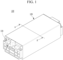
- FIG. 1 is a perspective view of a battery module according to an exemplary embodiment of the present invention
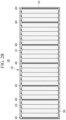
- FIGS. 2A and 2B are cross-sectional views along line A-A' of FIG. 1
- FIG. 3 is a perspective view of one battery cell included in a battery cell stack of FIG. 1
- FIG. 4 is a cross-sectional view of the battery cell of FIG. 3 and a cross-sectional view of a flame-retardant pad along line B-B' of FIG. 3
- FIG. 5 is a top view of the battery cell and the flame-retardant pad of FIG. 4
- FIG. 6 is an enlarged view of portion C of FIG. 5 .
- a battery module 100 includes a battery cell stack 101 including a plurality of battery cells 110, a housing 120 accommodating the battery cell stack 101, and a pair of end plates 130 each positioned on front and rear surfaces of the battery cell stack 101.
- the housing 120 may be in the form of a metal plate in which an upper surface, a lower surface, and both surfaces are integrated. That is, in the case of the housing 120 in the form of a square tube, a space in which the battery cell stack 101 may be accommodated is formed therein, and a pair of end plates 130 is coupled to both end portions in the form of the square tube.
- the present invention is not limited thereto, and various types of housings 120 may be applied.
- the housing 120 in a form in which the upper cover and the U-shaped frame are coupled is also possible, and is not particularly limited.
- the battery cell stack 101 includes a plurality of battery cells 110 stacked in one direction, and the plurality of battery cells 110 may be stacked standing parallel to a sidewall 124 of the housing 120 as illustrated in FIGS. 2A and 2B .
- the battery cell 110 is preferably a pouch-type battery cell.
- the battery cell 110 according to the present exemplary embodiment has a structure in which two electrode leads 111 and 112 face each other, and thus, protrude from one end portion 114a and the other end portion 114b of a battery body 113, respectively.
- An electrode lead included in each battery cell 110 is a positive electrode lead or a negative electrode lead, and end portions of the electrode leads 111 and 112 of each battery cell 110 may be bent in one direction, and thus, may contact end portions of electrode leads 111 and 112 of other adjacent battery cells 110.
- the two electrode leads 111 and 112 in contact with each other may be fixed to each other by welding or the like, and thus, an electrical connection between the battery cells 110 inside the battery cell stack 101 may be made.
- electrode leads aligned at both end portions of the battery cell stack 101 may be coupled to a bus bar frame (not illustrated) to be electrically connected to a bus bar mounted on the bus bar frame.
- the pair of end plates 130 covering the bus bar frames are provided on both open sides of the housing 120, respectively, and thus, may be coupled to the housing 120 by a method such as welding.
- the battery cell 110 may be manufactured by adhering both end portions 114a and 114b of the case 114 and both side surfaces 114c connecting the end portions 114a and 114b in a state in which the electrode assembly 121 is accommodated in the battery case 114.
- the battery cell 110 according to the present exemplary embodiment has a total of three sealing parts 114sa, 114sb, and 114sc, and the sealing parts 114sa, 114sb, and 114sc are sealed by a method such as thermal fusion, and the other one side part may be formed of a connection part 115.
- the electrode assembly 121 and an electrolytic solution may be accommodated in the battery case 114.
- the electrode assembly 121 may be configured in a form in which a positive electrode plate and a negative electrode plate are disposed with a separator interposed therebetween.
- the electrode assembly 121 may have a structure in which one positive electrode plate and one negative electrode plate are wound with a separator interposed therebetween, or a structure in which a plurality of positive electrode plates and a plurality of negative electrode plates are stacked with a separator interposed therebetween.
- Each of the positive and negative electrode plates may be formed as a structure in which an active material slurry is applied to an electrode current collector, in which the slurry is typically formed by stirring an active material, a conductive material, a binder, and a plasticizer in a state in which a solvent is added.
- Electrode tabs corresponding to each electrode plate may be formed in the uncoated region.
- the two electrode leads 111 and 112 respectively extending from a positive electrode tab and a negative electrode tab for electrical connection with an external terminal or a device may face each other, and thus, protrude at one end portion 114a and the other end portion 114b of the battery body 113, respectively.
- a thermally conductive resin layer 200 may be positioned between the battery cell stack 101 and a bottom of the housing 120.
- the thermally conductive resin layer 200 may transfer heat generated from the battery cell stack 101 to the bottom of the battery module 100 and also serve to fix the battery cell stack 101 to the bottom thereof.
- a plurality of flame-retardant pads 400 may be interposed between the battery cells 110. As illustrated in FIG. 2A , the plurality of flame-retardant pads 400 may be inserted one by one whenever three to four battery cells 110 are stacked, and thus, the plurality of flame-retardant pads 400 may be disposed at equal intervals. In addition, as illustrated in FIG. 2B , the plurality of flame-retardant pads 400 may be disposed at different intervals.
- the arrangement of the flame-retardant pads 400 is not particularly limited, and the number and thickness thereof may be appropriately adjusted as necessary.
- thermal impedance may increase when the thermal runaway occurs in the battery cells 110 in the battery module 100, thereby preventing or delaying transfer of heat between adjacent battery cells 110.
- the flame-retardant pad 400 may also be disposed between the battery cell 110 stacked on an outermost side of the battery cell stack 101 and the sidewall 124. When an issue such as the thermal runaway occurs within the battery module 100, the flame-retardant pad 400 may not only delay or block the transfer of heat from the corresponding battery cell to adjacent battery cells, but also absorb an expansion of the battery cell 110 to perform an expansion control.
- An area of the flame-retardant pad 400 is equal to or larger than that of the electrode assembly 121 included in the battery cell 110.
- the area of the flame-retardant pad 400 is formed to be smaller than that of the electrode assembly 121, a uniform pressure may not be applied to the battery cell 110, so problems such as performance degradation may occur.
- the flame-retardant pad 400 may serve to absorb swelling when the swelling of the battery cell 110 occurs inside the battery module 100, and when the area is smaller than the electrode assembly 121, the swelling that occurs in the portion where the flame-retardant pad 400 is not formed may not be absorbed.
- the area of the electrode assembly 121 may be determined by a length SE or the like of one side of the electrode assembly, and the area of the battery cell 110 may be determined by a length SC of one side of the battery cell. More specifically, the area of the electrode assembly 121 may be determined by an area of the positive electrode, the negative electrode, or the separator of the electrode assembly 121. In the battery cell 110, the electrode assembly 121 does not occupy the entire space inside the battery case 114, but a space for connection with the electrode leads 111 and 112 is further present. For example, the electrode assembly 121 may be about 90% of the area of the battery cell 110.
- the area of the flame-retardant pad 400 needs to be equal to the area of the electrode assembly 121 as described above.
- the area of the flame-retardant pad 400 is preferably equal to or larger than that of the negative electrode of the electrode assembly 121.
- the negative electrode is designed to be wider and longer than the positive electrode because the negative electrode must receive lithium ions from the positive electrode. Accordingly, it is not preferable that the area of the flame-retardant pad 400 is smaller than the area of the negative electrode, because swelling generated during charging and discharging cannot be sufficiently absorbed.
- the flame-retardant pad 400 should be formed equal to or larger than that of the electrode assembly 121 included in the battery cell 110, and as a result, the swelling control performance of the battery cell 110 by the flame-retardant pad 400 may also be maintained excellently. In addition, it is possible to prevent the swelling from being concentrated in a local portion of the battery cell 110 to deteriorate the battery performance.
- the area of the flame-retardant pad 400 may also equal to or larger than that of the electrode assembly 121, it is preferably a size that does not extend to a portion where the electrode leads 111 and 112 coupled to the electrode tabs extending from the electrode assembly 121 are disposed.
- the flame-retardant pad 400 When the flame-retardant pad 400 extends to the portion where the electrode leads 111 and 112 are disposed, interference occurs in the process of assembling for electrical connection between the electrode leads 111 and 112 and other components, which may not be desirable. When the flame-retardant pad 400 extends to the portion where the electrode leads 111 and 112 are disposed, it is not preferable because interference occurs in the process of assembling for electrical connection between the electrode leads 111 and 112 and other components. In addition, damage to each other may occur due to contact between the flame-retardant pad 400 and the electrode leads 111 and 112. Therefore, it is preferable that the area of the flame-retardant pad 400 is set so that the electrode leads 111 and 112 are not disposed in the portion protruding from the electrode cell 110.
- the flame-retardant pad 400 may be formed of a silicone foam pad to prevent the transfer of heat and flame generated to the battery cell 110.
- the silicone foam pad is a foam pad with pores formed therein, and has high thermal and chemical stability, and has excellent flame retardant and thermal insulation properties. In particular, it is possible to secure better flame-retardant properties by applying a silicone foam pad made of thermosetting foamed silicone.
- the silicone foam pad is suitably applicable in that it has high elasticity (high compression resistance and high rebound elasticity) and high durability.
- the battery cell 110 repeatedly contracts and expands.
- high elasticity is required.
- the silicone foam pad may be used.
- the silicone foam pad may exert a compressive force of 10 kPA to 100 kPa in 10% to 60% of a compression range (compression force deflection (CFD)).
- CFD 25% (ASTM D 3574) value may be 0.05 ⁇ 0.18 kgf/cm 2 , as an initial value.
- the silicone foam preferably has a long-term restoration lifespan (durability) of 10 years or more.
- the content of hydrocarbon is small to minimize the collapse of the structure of the battery cell 110 due to the combustion under the condition that the thermal runaway occurs in the battery cell 110. That is, as hydrocarbon is thermally decomposed into gas phases such as CO, CO 2 , and water vapor by the combustion reaction when thermal runaway occurs in the battery cell, the weight loss of the flame-retardant pad may increase and the structure of the battery cell may collapse, so the content of hydrocarbon in the silicone foam pad is preferably adjusted as little as possible.
- the foam pad does not contain a halogen element in order not to generate a toxic gas during the combustion,.
- FIG. 7 is a graph illustrating results of a thermal runaway experiment for the example of the present invention and the comparative example.
- the battery module included 12 battery cells, a flame-retardant pad was applied to every 6 battery cells, and a total of two flame-retardant pads were inserted to configure the battery module.
- the battery module was constructed by applying a polyurethane pad instead of the flame-retardant pad. The battery module was heated by attaching a heating pad to an end of the battery module, and the thermal runaway occurred at about 140 seconds after starting heating by applying voltage to the heating plate. After that, the time point of the voltage drop of the entire battery module was measured.
- the battery module voltage became 0 at about 300 seconds, but in the Example, the voltage became 0 at about 420 seconds. That is, according to the embodiment of the present invention, it was confirmed that the delay or blocking of the transfer of heat from a cell where the thermal runaway occurred to adjacent cells was appropriately performed, and thus the time point of the voltage drop due to the thermal runaway is delayed as much as possible.
- the flame-retardant pad 400 between the battery cells 110 of the battery module 100, it is possible to delay or block the transfer of heat to adjacent battery cells when the thermal runaway occurs, so the safety of the battery may be improved.
- the area of the flame-retardant pad 400 equal to or larger than that of the electrode assembly 121, it is possible to prevent problems such as damage to the battery cells and electrodes and deterioration in performance/cycle-life which may be caused by the formation of non-uniform surface pressure between the battery cells.
- the flame-retardant pad 400 may be modified in various forms and applied to the battery module 100.
- flame-retardant pads according to another exemplary embodiments of the present invention will be described with reference to FIGS. 8 and 9 .
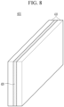
- FIG. 8 is an illustration of a flame-retardant pad according to a second exemplary embodiment of the present invention
- FIG. 9 is an illustration of a flame-retardant pad according to a third exemplary embodiment of the present invention.
- a flame-retardant pad 401 includes two silicone foam pads 410, and a mica sheet 420 interposed between the two silicone foam pads 410.
- the flame-retardant pad 401 further including the mica sheet 420 having excellent heat resistance between the silicone foam pads 410 as described above, it is possible to more effectively prevent the structural collapse of the silicone foam pad 410 due to the thermal decomposition under the thermal runaway condition.
- the flame-retardant pad 402 according to the third exemplary embodiment of the present invention further includes a coating film 430 formed on the silicone foam pad 410.
- the coating film 430 may be applied to improve process easiness and reduce a friction force between the flame-retardant pad 402 and the battery cell 110 when the battery cell stack 101 of the battery module 100 is manufactured.
- the coating film 430 may be attached to the silicone foam pad 410 by an adhesive or the like.
- the coating film 430 includes at least one of polyethylene terephthalate (PET), polyvinyl chloride (PVC), polypropylene (PP) and polycarbonate (PC), but is not particularly limited.
- the silicone foam pad having a fine pattern formed on its surface may be used as the flame-retardant pad 400.
- the fine pattern By forming the fine pattern, it is possible to prevent foreign substances from adhering to the flame-retardant pad 400, and it is possible to obtain a desired degree of frictional force.
- the shape and size of the fine pattern are not particularly limited.
- various properties may be imparted to the flame-retardant pad 400 by controlling the pores inside the silicone foam pad used as the flame-retardant pad 400. That is, when manufacturing the silicone foam pad, a ratio and size of pores may be adjusted (that is, density is adjusted) by adjusting an addition ratio of a foaming agent and a curing agent. In this case, as the density of the pores increases, the thermal insulation property may be improved, and as the density of the pores decreases, the mechanical properties may be improved. Accordingly, it is possible to obtain a silicone foam pad having desired thermal insulation property and mechanical properties by properly adjusting the density of the pores.
- the physical properties of the silicone foam pad may be reinforced. These additional materials may be added to the inside of the silicone foam pad by being mixed together when the foaming agent and the curing agent are mixed to form the silicone foam pad.
- an inorganic refractory filler may be added to the pores inside the silicone foam pad to reinforce the heat resistance of the silicone foam pad.
- the inorganic refractory filler may include at least one of calcium carbonate (CaCO 3 ), mica, glass fiber, and mineral fiber composite.
- the flame retardant filler may be further added to the pores inside the silicone foam pad so that the silicone foam pad may have flame retardant or self-extinguishing properties.
- the flame retardant filler at least one of nano-bismuth oxide, aluminum oxide nano-powder, and organic nano-clay may be used, but is not particularly limited. By adding a flame retardant filler, it is possible to have a flame retardancy suitable for underwriter's laboratory (UL) standards.
- the extinguishing agent at least one selected from the group consisting of inorganic carbonates, inorganic phosphates, and inorganic sulfates may be used, and the extinguishing agent is not particularly limited.
- FIG. 10 is an illustration of a flame-retardant pad according to a fourth exemplary embodiment of the present invention.
- a flame-retardant pad 403 according to the fourth exemplary embodiment further includes at least one thermal insulation-flame retarding member 440 formed on at least one surface of the silicone form pad 410.
- the thermal insulation-flame retarding member 440 may prevent the flame from spreading when a flame is generated.
- the thermal insulation-flame retarding member 440 can prevent heat diffusion to adjacent cells by the thermal insulation performance of the thermal insulation-flame retarding member 440, even when a portion of the patter module 100 is in a high-temperature state due to thermal runaway occurring in any one cell of the battery module 100.
- the thermal insulation-flame retarding member 440 which is made of a material different from the silicone foam pad 410, it is possible to more reliably prevent the spread of flame and heat between adjacent cells.
- the thermal insulation-flame retarding member 440 may be formed on any one surface or both surfaces of the silicone foam pad 410, or may be added as an inner layer of the silicone foam pad 410.
- heat and flame generated from the battery cell can be in direct contact with the thermal insulation-flame retarded member 440, so that heat and flame can be more effectively prevented.
- thermal insulation-flame retarding member 440 at least one selected from a glass fiber reinforced pad (GFRP) and a carbon fiber reinforced pad (CFRP) may be used.
- GFRP glass fiber reinforced pad
- CFRP carbon fiber reinforced pad
- FIGS 11 and 12 are illustrations of flame-retardant pads according to fifth and sixth exemplary embodiments of the present invention.
- the flame-retardant pads 404 and 405 according to the fifth and sixth exemplary embodiments include multilayered silicone foam pads 410a and 410b.
- the flame-retardant pads 404 and 405 include at least one first silicone foam pad 410a and at least one second silicone foam pad 410b.
- the density of the first silicone foam pad 410a is higher than the density of the second silicone foam pad 41 0b.
- the first silicone foam pad 410a and second silicone foam pad 410b have a configuration in which the first silicone foam pad 410a is disposed in the center and the second silicone foam pads 410b are disposed on both sides of the first silicone foam pad 410a, as shown in FIG. 11 , or have a configuration in which the second silicone foam pad 410b is disposed in the center and the first silicone foam pads 410a are disposed on both sides of the second silicone foam pad 410b, as shown in FIG. 12 .
- the flame-retardant pads 404 and 405 can effectively control the expansion of the battery cell and effectively delay or block the transfer of heat.
- the first silicone foam pad 410a having a high density is advantageous in more effectively delaying or blocking heat transfer under a thermal runaway condition, but may be somewhat disadvantageous in controlling cell expansion.
- the second silicone foam pad 410b having a low density it is possible to have a buffering effect on the expansion of the battery cell 110 and thus effectively achieve the expansion control of the battery cell 110.
- the density of the silicone foam pad 410a and 410b may be controlled by adjusting the size and the number of pores inside the silicone foam pad 410a and 41 0b, but is not limited thereto.
- FIG. 13 is an illustrations of a flame-retardant pad according to a seventh exemplary embodiment of the present invention.
- the flame-retardant pad 406 according to the seventh exemplary embodiment further includes at least one foaming coating layer 450 formed on at least one surface of the silicone form pad 410.
- the foam coating layer 450 has a property of expanding when the temperature is rapidly increased due to thermal runaway occurring inside the battery cell 110. Since the space between the cells may be expanded by this property, the flame-retardant pad 406 secures a space to thermally insulate the cells when exposed to high temperatures. Thereby the flame-retardant pad 406 may more effectively delay or block the transfer of heat.
- the foaming coating layer 450 a coating of a foam material that responds to temperature can be appropriately selected and used.
- a flame retardant including phosphorus may be used.
- the foaming coating layer 450 may undergo an endothermic decomposition reaction at a high temperature to cause the foaming coating layer to expand, thereby not only securing a space between cells, but also blocking or delaying heat transfer by forming a carbonized layer, which is a porous and thermally stable layer with very low thermal conductivity.
- the fourth to seventh exemplary embodiments of the present invention it is possible to provide a flame-retardant pad that can more effectively absorb the swelling of the battery cell while having better flame retardancy, heat insulation, and mechanical properties, by adding an additional layer to the silicone foam pad used as the flame-retardant pad, or by changing the physical properties of the silicone foam pad. Accordingly, it is possible to effectively control the swelling of the battery cell as the temperature rises in the battery module, and to more effectively delay or block the transfer of heat and suppress the combustion reaction even in a thermal runaway condition at a high temperature. Meanwhile, one or more battery modules according to an exemplary embodiment of the present invention may be packaged in a pack case to form a battery pack.
- the above-described battery module and battery pack including the same may be applied to various devices.
- a device may be applied to transportation means such as an electric bicycle, an electric vehicle, and a hybrid vehicle, but the present invention is not limited thereto and is applicable to various devices that can use a battery module and a battery pack including the same, which belongs to the scope of the present invention.
Landscapes
- Chemical & Material Sciences (AREA)
- Chemical Kinetics & Catalysis (AREA)
- General Chemical & Material Sciences (AREA)
- Electrochemistry (AREA)
- Engineering & Computer Science (AREA)
- Manufacturing & Machinery (AREA)
- Business, Economics & Management (AREA)
- Emergency Management (AREA)
- Health & Medical Sciences (AREA)
- Public Health (AREA)
- Battery Mounting, Suspending (AREA)
- Secondary Cells (AREA)
Abstract
Description
- This application claims the benefit of priority based on
Korean Patent Applications No. 10-2020-0110448 dated August 31, 2020 10-2021-0114614 dated August 30, 2021 - The present invention relates to a battery module and a battery pack including the same, and more particularly, to a battery module having improved safety by delaying or blocking transfer of heat between cells, and a battery pack including the same.
- Secondary batteries that are easy to use with various product groups and have electrical characteristics such as high energy density have been generally applied to not only portable devices, but also electric vehicles, hybrid vehicles, or power storage devices which are driven by an electric drive source. These secondary batteries are attracting attention as a new energy source for improving eco-friendliness and energy efficiency in that the use of fossil fuels may be dramatically reduced and no by-products may be generated from the use of energy.
- One to three battery cells are used per device in small mobile devices, but high-output and high-capacity battery cells are required for medium and large devices such as automobiles. Accordingly, a medium and large battery module in which a plurality of battery cells are electrically connected has been used.
- Since it is preferable that the medium and large battery module should be manufactured in a lightweight and thin structure if possible, a prismatic battery, a pouch-type battery, etc. that may be stacked with a high degree of integration and have a small weight and high capacity have been mainly used as battery cells of the medium and large battery module. The battery module includes a frame member for accommodating a battery cell stack in an internal space thereof while covering top, bottom, left, and right surfaces of the battery cell stack to protect the cell stack from external impact, heat, or vibrations.
- As described above, since the plurality of battery cells included in the battery module are stacked, when problems such as thermal runaway occur in any one of the battery cells, heat and flame generated from the cell may easily transfer to adjacent battery cells.
- The present invention has been made in an effort to provide a battery module and a battery pack including the same having advantages of suppressing a chain combustion reaction by delaying or blocking transfer of heat to adjacent battery cells even if a problem such as thermal runaway occurs in any one of the battery cells inside the battery module.
- However, problems to be solved by exemplary embodiments of the present invention are not limited to the abovementioned problems, and can be variously expanded within the scope of the technical idea included in the present invention.
- An exemplary embodiment of the present invention provides a battery module including: a battery cell stack in which a plurality of battery cells each including an electrode assembly are stacked; a housing accommodating the battery cell stack; and at least one flame-retardant pad interposed between at least one pair of adjacent battery cells among the plurality of battery cells or between the battery cell stack and the housing, in which an area of the flame-retardant pad is equal to or larger than that of the electrode assembly.
- At least two or more of the flame-retardant pads may be provided, and at least one battery cell may be positioned between two adjacent flame-retardant pads among the flame-retardant pads.
- A spacing between the flame-retardant pads may be the same or different.
- The flame-retardant pad may include a silicone foam pad.
- The flame-retardant pad may include two silicone foam pads and a mica sheet interposed between the two silicone foam pads.
- The battery module may further include a coating film formed on one surface of the silicone foam pad.
- The coating film may include at least one of polyethylene terephthalate (PET), polyvinyl chloride (PVC), polypropylene (PP), and polycarbonate (PC).
- A fine pattern may be formed on a surface of the silicone foam pad.
- The silicone foam pad may further include an inorganic refractory filler filling pores therein.
- The inorganic refractory filler may include at least one of calcium carbonate (CaCO3), mica, glass fiber, and mineral fiber composite.
- The silicone foam pad may further include an extinguishing agent that fills the pores therein.
- The extinguishing agent may be at least one selected from the group consisting of inorganic carbonates, inorganic phosphates, and inorganic sulfates.
- The silicone foam pad may further include a flame-retardant filler filling the pores therein.
- The flame-retardant filler may be at least one selected from the group consisting of nano-bismuth oxide, aluminum oxide nano-powder, and organic nano-clay.
- An area of the flame-retardant pad may be equal to or larger than that of a negative electrode of the electrode assembly.
- The flame-retardant pad may not overlap a portion where electrode leads coupled to the electrode assembly are disposed.
- The silicone foam pad may not contain a halogen element.
- The flame-retardant pad may further include at least one thermal insulation-flame retarded member formed on at least one surface of the silicone foam pad.
- The thermal insulation-flame retarded member may be at least one selected from the group consisting of glass fiber reinforced pad and carbon fiber reinforced pad.
- The silicone foam pad may include at least one first silicone foam pad and at least one second silicone foam pad, and the density of the first silicone foam pad may be higher than the density of the second silicone foam pad.
- The silicone foam pad may include one of the first silicone foam pad, and two of the second silicone foam pads disposed on both sides of the first silicone foam pads.
- The silicone foam pad may include one of the second silicone foam pad, and two of the first silicone foam pads disposed on both sides of the second silicone foam pads.
- The flame-retardant may further include at least one foam coating layer formed on at least one surface of the silicone foam pad.
- The foam coating layer may expand as the surrounding temperature rises.
- Another exemplary embodiment of the present invention provides a battery pack including: the at least one battery module described above; and a pack case packaging the at least one battery module.
- According to exemplary embodiments, by including a flame-retardant pad between battery cells, even if a problem such as thermal runaway occurs in any one battery cell inside the battery module, it is possible to delay or block transfer of heat and flame to adjacent battery cells and improve safety of the module by suppressing a chain combustion reaction.
-
-
FIG. 1 is a perspective view of a battery module according to an exemplary embodiment of the present invention. -
FIGS. 2A and2B are cross-sectional views along line A-A' ofFIG. 1 . -
FIG. 3 is a perspective view of one battery cell included in a battery cell stack ofFIG. 1 . -
FIG. 4 is a cross-sectional view of the battery cell ofFIG. 3 and a cross-sectional view of a flame-retardant pad along line B-B' ofFIG. 3 . -
FIG. 5 is a top view of the battery cell and the flame-retardant pad ofFIG. 4 . -
FIG. 6 is an enlarged view of portion C ofFIG. 5 . -
FIG. 7 is a graph illustrating results of a thermal runaway experiment according to an example and a comparative example. -
FIG. 8 is an illustration of a flame-retardant pad according to a second embodiment of the present invention. -
FIG. 9 is an illustration of a flame-retardant pad according to a third embodiment of the present invention. -
FIG. 10 to FIG. 13 are illustrations of flame-retardant pads according to fourth to seventh embodiments of the present invention. - Hereinafter, several exemplary embodiments of the present invention will be described in detail with reference to the accompanying drawings so that those skilled in the art to which the present invention pertains may easily practice the present invention. However, the present invention may be implemented in various different forms and is not limited to exemplary embodiments provided herein.
- Portions unrelated to the description will be omitted in order to obviously describe the present invention, and similar components will be denoted by the same or similar reference numerals throughout the present specification.
- In addition, since sizes and thicknesses of the respective components illustrated in the drawings are arbitrarily illustrated for convenience of explanation, the present invention is not necessarily limited to those illustrated in the drawings. In the drawings, the thickness of layers, films, panels, regions, etc., are exaggerated for clarity. In addition, in the accompanying drawings, thicknesses of some of layers and regions have been exaggerated for convenience of explanation.
- In addition, it will be understood that when an element such as a layer, film, region, or substrate is referred to as being "on" another element, it can be directly on the other element or intervening elements may also be present. In contrast, when an element is referred to as being "directly on" another element, there are no intervening elements present. In addition, the fact that an element is positioned "above" or "on" a reference element means that it is positioned above or below the reference element, and is not necessarily means that is positioned "above" or "on" in an opposite direction to gravity.
- In addition, unless explicitly described to the contrary, the word "comprise", and variations such as "comprises" or "comprising", will be understood to imply the inclusion of stated elements but not the exclusion of any other elements.
- Further, throughout the specification, the word "plan view" refers to a view when a target is viewed from the top, and the word "cross-sectional view" refers to a view when a cross section of a target taken along a vertical direction is viewed from the side.
- Hereinafter, a battery module according to an exemplary embodiment of the present invention will be described with reference to
FIGS. 1 to 6 . -
FIG. 1 is a perspective view of a battery module according to an exemplary embodiment of the present invention,FIGS. 2A and2B are cross-sectional views along line A-A' ofFIG. 1 ,FIG. 3 is a perspective view of one battery cell included in a battery cell stack ofFIG. 1 ,FIG. 4 is a cross-sectional view of the battery cell ofFIG. 3 and a cross-sectional view of a flame-retardant pad along line B-B' ofFIG. 3 ,FIG. 5 is a top view of the battery cell and the flame-retardant pad ofFIG. 4 , andFIG. 6 is an enlarged view of portion C ofFIG. 5 . - As illustrated in
FIGS. 1 ,2A and2B , abattery module 100 according to the present exemplary embodiment includes a battery cell stack 101 including a plurality ofbattery cells 110, ahousing 120 accommodating the battery cell stack 101, and a pair ofend plates 130 each positioned on front and rear surfaces of the battery cell stack 101. - As illustrated in
FIG. 1 , thehousing 120 may be in the form of a metal plate in which an upper surface, a lower surface, and both surfaces are integrated. That is, in the case of thehousing 120 in the form of a square tube, a space in which the battery cell stack 101 may be accommodated is formed therein, and a pair ofend plates 130 is coupled to both end portions in the form of the square tube. However, the present invention is not limited thereto, and various types ofhousings 120 may be applied. As a possible modification, thehousing 120 in a form in which the upper cover and the U-shaped frame are coupled is also possible, and is not particularly limited. - The battery cell stack 101 includes a plurality of
battery cells 110 stacked in one direction, and the plurality ofbattery cells 110 may be stacked standing parallel to asidewall 124 of thehousing 120 as illustrated inFIGS. 2A and2B . - The
battery cell 110 is preferably a pouch-type battery cell. For example, as illustrated inFIG. 3 , thebattery cell 110 according to the present exemplary embodiment has a structure in which two electrode leads 111 and 112 face each other, and thus, protrude from oneend portion 114a and theother end portion 114b of abattery body 113, respectively. An electrode lead included in eachbattery cell 110 is a positive electrode lead or a negative electrode lead, and end portions of the electrode leads 111 and 112 of eachbattery cell 110 may be bent in one direction, and thus, may contact end portions of electrode leads 111 and 112 of otheradjacent battery cells 110. The two electrode leads 111 and 112 in contact with each other may be fixed to each other by welding or the like, and thus, an electrical connection between thebattery cells 110 inside the battery cell stack 101 may be made. In addition, electrode leads aligned at both end portions of the battery cell stack 101 may be coupled to a bus bar frame (not illustrated) to be electrically connected to a bus bar mounted on the bus bar frame. The pair ofend plates 130 covering the bus bar frames are provided on both open sides of thehousing 120, respectively, and thus, may be coupled to thehousing 120 by a method such as welding. - The
battery cell 110 may be manufactured by adhering bothend portions case 114 and both side surfaces 114c connecting theend portions electrode assembly 121 is accommodated in thebattery case 114. In other words, thebattery cell 110 according to the present exemplary embodiment has a total of three sealing parts 114sa, 114sb, and 114sc, and the sealing parts 114sa, 114sb, and 114sc are sealed by a method such as thermal fusion, and the other one side part may be formed of aconnection part 115. - The
electrode assembly 121 and an electrolytic solution may be accommodated in thebattery case 114. Theelectrode assembly 121 may be configured in a form in which a positive electrode plate and a negative electrode plate are disposed with a separator interposed therebetween. In this case, theelectrode assembly 121 may have a structure in which one positive electrode plate and one negative electrode plate are wound with a separator interposed therebetween, or a structure in which a plurality of positive electrode plates and a plurality of negative electrode plates are stacked with a separator interposed therebetween. Each of the positive and negative electrode plates may be formed as a structure in which an active material slurry is applied to an electrode current collector, in which the slurry is typically formed by stirring an active material, a conductive material, a binder, and a plasticizer in a state in which a solvent is added. - An uncoated region to which the slurry is not applied to the electrode plate may exist in the
electrode assembly 121, and electrode tabs corresponding to each electrode plate may be formed in the uncoated region. In this case, the two electrode leads 111 and 112 respectively extending from a positive electrode tab and a negative electrode tab for electrical connection with an external terminal or a device may face each other, and thus, protrude at oneend portion 114a and theother end portion 114b of thebattery body 113, respectively. - A thermally
conductive resin layer 200 may be positioned between the battery cell stack 101 and a bottom of thehousing 120. The thermallyconductive resin layer 200 may transfer heat generated from the battery cell stack 101 to the bottom of thebattery module 100 and also serve to fix the battery cell stack 101 to the bottom thereof. - As illustrated in
FIGS. 2A and2B , a plurality of flame-retardant pads 400 may be interposed between thebattery cells 110. As illustrated inFIG. 2A , the plurality of flame-retardant pads 400 may be inserted one by one whenever three to fourbattery cells 110 are stacked, and thus, the plurality of flame-retardant pads 400 may be disposed at equal intervals. In addition, as illustrated inFIG. 2B , the plurality of flame-retardant pads 400 may be disposed at different intervals. The arrangement of the flame-retardant pads 400 is not particularly limited, and the number and thickness thereof may be appropriately adjusted as necessary. In this way, by arranging the flame-retardant pads 400 to be spaced at equal or non-equal intervals, thermal impedance may increase when the thermal runaway occurs in thebattery cells 110 in thebattery module 100, thereby preventing or delaying transfer of heat betweenadjacent battery cells 110. In addition, the flame-retardant pad 400 may also be disposed between thebattery cell 110 stacked on an outermost side of the battery cell stack 101 and thesidewall 124. When an issue such as the thermal runaway occurs within thebattery module 100, the flame-retardant pad 400 may not only delay or block the transfer of heat from the corresponding battery cell to adjacent battery cells, but also absorb an expansion of thebattery cell 110 to perform an expansion control. - An area of the flame-
retardant pad 400 is equal to or larger than that of theelectrode assembly 121 included in thebattery cell 110. When the area of the flame-retardant pad 400 is formed to be smaller than that of theelectrode assembly 121, a uniform pressure may not be applied to thebattery cell 110, so problems such as performance degradation may occur. In particular, the flame-retardant pad 400 may serve to absorb swelling when the swelling of thebattery cell 110 occurs inside thebattery module 100, and when the area is smaller than theelectrode assembly 121, the swelling that occurs in the portion where the flame-retardant pad 400 is not formed may not be absorbed. - As illustrated in
FIG. 4 , the area of theelectrode assembly 121 may be determined by a length SE or the like of one side of the electrode assembly, and the area of thebattery cell 110 may be determined by a length SC of one side of the battery cell. More specifically, the area of theelectrode assembly 121 may be determined by an area of the positive electrode, the negative electrode, or the separator of theelectrode assembly 121. In thebattery cell 110, theelectrode assembly 121 does not occupy the entire space inside thebattery case 114, but a space for connection with the electrode leads 111 and 112 is further present. For example, theelectrode assembly 121 may be about 90% of the area of thebattery cell 110. In this case, in order to effectively control the swelling of thebattery cell 110, at least the area of the flame-retardant pad 400 needs to be equal to the area of theelectrode assembly 121 as described above. When the flame-retardant pad 400 supports an area smaller than that of theelectrode assembly 121, the swelling that occurs is rather concentrated on a portion that does not correspond to the flame-retardant pad 400, and thus, thebattery cell 110 may be damaged. More specifically, the area of the flame-retardant pad 400 is preferably equal to or larger than that of the negative electrode of theelectrode assembly 121. For example, in the chemical reaction of a lithium ion battery, the negative electrode is designed to be wider and longer than the positive electrode because the negative electrode must receive lithium ions from the positive electrode. Accordingly, it is not preferable that the area of the flame-retardant pad 400 is smaller than the area of the negative electrode, because swelling generated during charging and discharging cannot be sufficiently absorbed. - Therefore, as illustrated in
FIGS. 4 to 6 , the flame-retardant pad 400 should be formed equal to or larger than that of theelectrode assembly 121 included in thebattery cell 110, and as a result, the swelling control performance of thebattery cell 110 by the flame-retardant pad 400 may also be maintained excellently. In addition, it is possible to prevent the swelling from being concentrated in a local portion of thebattery cell 110 to deteriorate the battery performance. - In addition, while the area of the flame-
retardant pad 400 may also equal to or larger than that of theelectrode assembly 121, it is preferably a size that does not extend to a portion where the electrode leads 111 and 112 coupled to the electrode tabs extending from theelectrode assembly 121 are disposed. - When the flame-
retardant pad 400 extends to the portion where the electrode leads 111 and 112 are disposed, interference occurs in the process of assembling for electrical connection between the electrode leads 111 and 112 and other components, which may not be desirable. When the flame-retardant pad 400 extends to the portion where the electrode leads 111 and 112 are disposed, it is not preferable because interference occurs in the process of assembling for electrical connection between the electrode leads 111 and 112 and other components. In addition, damage to each other may occur due to contact between the flame-retardant pad 400 and the electrode leads 111 and 112. Therefore, it is preferable that the area of the flame-retardant pad 400 is set so that the electrode leads 111 and 112 are not disposed in the portion protruding from theelectrode cell 110. - The flame-
retardant pad 400 may be formed of a silicone foam pad to prevent the transfer of heat and flame generated to thebattery cell 110. The silicone foam pad is a foam pad with pores formed therein, and has high thermal and chemical stability, and has excellent flame retardant and thermal insulation properties. In particular, it is possible to secure better flame-retardant properties by applying a silicone foam pad made of thermosetting foamed silicone. - In addition, from the viewpoint of the swelling control of the
battery cell 110 described above, the silicone foam pad is suitably applicable in that it has high elasticity (high compression resistance and high rebound elasticity) and high durability. In particular, according to the swelling of thebattery cell 110, thebattery cell 110 repeatedly contracts and expands. In order to withstand the repeated contraction and expansion of thebattery cell 110 and prevent thebattery cell 110 from being deformed, high elasticity is required. To this end, the silicone foam pad may be used. Specifically, the silicone foam pad may exert a compressive force of 10 kPA to 100 kPa in 10% to 60% of a compression range (compression force deflection (CFD)). For example, CFD 25% (ASTM D 3574) value may be 0.05~0.18 kgf/cm2, as an initial value. Further, the silicone foam preferably has a long-term restoration lifespan (durability) of 10 years or more. - In the case of the silicone foam pad, it is preferable that the content of hydrocarbon is small to minimize the collapse of the structure of the
battery cell 110 due to the combustion under the condition that the thermal runaway occurs in thebattery cell 110. That is, as hydrocarbon is thermally decomposed into gas phases such as CO, CO2, and water vapor by the combustion reaction when thermal runaway occurs in the battery cell, the weight loss of the flame-retardant pad may increase and the structure of the battery cell may collapse, so the content of hydrocarbon in the silicone foam pad is preferably adjusted as little as possible. In addition, it is preferable that the foam pad does not contain a halogen element in order not to generate a toxic gas during the combustion,. - An experiment was performed at a time of a voltage drop when the thermal runaway occurs for the
battery module 100 to which the silicone foam pad is applied as the flame-retardant pad 400 and the battery module to which the flame-retardant pad 400 is not applied. -
FIG. 7 is a graph illustrating results of a thermal runaway experiment for the example of the present invention and the comparative example. - In the Example, the battery module included 12 battery cells, a flame-retardant pad was applied to every 6 battery cells, and a total of two flame-retardant pads were inserted to configure the battery module. In the Comparative Example, in the same configuration, the battery module was constructed by applying a polyurethane pad instead of the flame-retardant pad. The battery module was heated by attaching a heating pad to an end of the battery module, and the thermal runaway occurred at about 140 seconds after starting heating by applying voltage to the heating plate. After that, the time point of the voltage drop of the entire battery module was measured.
- As illustrated in
FIG. 7 , in Comparative Example, the battery module voltage became 0 at about 300 seconds, but in the Example, the voltage became 0 at about 420 seconds. That is, according to the embodiment of the present invention, it was confirmed that the delay or blocking of the transfer of heat from a cell where the thermal runaway occurred to adjacent cells was appropriately performed, and thus the time point of the voltage drop due to the thermal runaway is delayed as much as possible. - As described above, according to the exemplary embodiment, by providing the flame-
retardant pad 400 between thebattery cells 110 of thebattery module 100, it is possible to delay or block the transfer of heat to adjacent battery cells when the thermal runaway occurs, so the safety of the battery may be improved. In addition, by making the area of the flame-retardant pad 400 equal to or larger than that of theelectrode assembly 121, it is possible to prevent problems such as damage to the battery cells and electrodes and deterioration in performance/cycle-life which may be caused by the formation of non-uniform surface pressure between the battery cells. - The flame-
retardant pad 400 may be modified in various forms and applied to thebattery module 100. Hereinafter, flame-retardant pads according to another exemplary embodiments of the present invention will be described with reference toFIGS. 8 and9 . -
FIG. 8 is an illustration of a flame-retardant pad according to a second exemplary embodiment of the present invention andFIG. 9 is an illustration of a flame-retardant pad according to a third exemplary embodiment of the present invention. - As illustrated in
FIG. 8 , a flame-retardant pad 401 according to the second exemplary embodiment of the present invention includes twosilicone foam pads 410, and amica sheet 420 interposed between the twosilicone foam pads 410. By applying the flame-retardant pad 401 further including themica sheet 420 having excellent heat resistance between thesilicone foam pads 410 as described above, it is possible to more effectively prevent the structural collapse of thesilicone foam pad 410 due to the thermal decomposition under the thermal runaway condition. - As illustrated in
FIG. 9 , the flame-retardant pad 402 according to the third exemplary embodiment of the present invention further includes acoating film 430 formed on thesilicone foam pad 410. Thecoating film 430 may be applied to improve process easiness and reduce a friction force between the flame-retardant pad 402 and thebattery cell 110 when the battery cell stack 101 of thebattery module 100 is manufactured. Thecoating film 430 may be attached to thesilicone foam pad 410 by an adhesive or the like. Thecoating film 430 includes at least one of polyethylene terephthalate (PET), polyvinyl chloride (PVC), polypropylene (PP) and polycarbonate (PC), but is not particularly limited. - In another modified example, the silicone foam pad having a fine pattern formed on its surface may be used as the flame-
retardant pad 400. By forming the fine pattern, it is possible to prevent foreign substances from adhering to the flame-retardant pad 400, and it is possible to obtain a desired degree of frictional force. The shape and size of the fine pattern are not particularly limited. - In another modified example, various properties may be imparted to the flame-
retardant pad 400 by controlling the pores inside the silicone foam pad used as the flame-retardant pad 400. That is, when manufacturing the silicone foam pad, a ratio and size of pores may be adjusted (that is, density is adjusted) by adjusting an addition ratio of a foaming agent and a curing agent. In this case, as the density of the pores increases, the thermal insulation property may be improved, and as the density of the pores decreases, the mechanical properties may be improved. Accordingly, it is possible to obtain a silicone foam pad having desired thermal insulation property and mechanical properties by properly adjusting the density of the pores. - In addition, by filling the pores inside the silicone foam pad with various additional materials, the physical properties of the silicone foam pad may be reinforced. These additional materials may be added to the inside of the silicone foam pad by being mixed together when the foaming agent and the curing agent are mixed to form the silicone foam pad.
- For example, an inorganic refractory filler may be added to the pores inside the silicone foam pad to reinforce the heat resistance of the silicone foam pad. The inorganic refractory filler may include at least one of calcium carbonate (CaCO3), mica, glass fiber, and mineral fiber composite.
- In addition, the flame retardant filler may be further added to the pores inside the silicone foam pad so that the silicone foam pad may have flame retardant or self-extinguishing properties. As the flame retardant filler, at least one of nano-bismuth oxide, aluminum oxide nano-powder, and organic nano-clay may be used, but is not particularly limited. By adding a flame retardant filler, it is possible to have a flame retardancy suitable for underwriter's laboratory (UL) standards.
- Meanwhile, by filling the pores inside the silicone foam pad with extinguishing agents to allow carbon dioxide gas to be released under thermal runaway conditions, it is possible to provide a self-extinguishing function capable of suppressing the combustion reaction itself. As the extinguishing agent, at least one selected from the group consisting of inorganic carbonates, inorganic phosphates, and inorganic sulfates may be used, and the extinguishing agent is not particularly limited.
- As such, according to other exemplary embodiments of the present invention, it is possible to provide a flame-retardant pad having better flame retardancy, heat insulation, and mechanical properties by reinforcing various additional physical properties of the silicone foam pad used as the flame-retardant pad. Therefore, in the case of a thermal runaway condition in the battery module, it is possible to more effectively delay or block the transfer of heat and suppress the combustion reaction.
- Hereinafter, flame-retardant pads according to other exemplary embodiments of the present invention will be described with reference to
FIGS. 10 and13 . -
FIG. 10 is an illustration of a flame-retardant pad according to a fourth exemplary embodiment of the present invention. As illustrated inFIG. 10 , a flame-retardant pad 403 according to the fourth exemplary embodiment further includes at least one thermal insulation-flame retarding member 440 formed on at least one surface of thesilicone form pad 410. The thermal insulation-flame retarding member 440 may prevent the flame from spreading when a flame is generated. In addition, the thermal insulation-flame retarding member 440 can prevent heat diffusion to adjacent cells by the thermal insulation performance of the thermal insulation-flame retarding member 440, even when a portion of thepatter module 100 is in a high-temperature state due to thermal runaway occurring in any one cell of thebattery module 100. In particular, by adding the thermal insulation-flame retarding member 440, which is made of a material different from thesilicone foam pad 410, to the surface of thesilicone foam pad 410, it is possible to more reliably prevent the spread of flame and heat between adjacent cells. The thermal insulation-flame retarding member 440 may be formed on any one surface or both surfaces of thesilicone foam pad 410, or may be added as an inner layer of thesilicone foam pad 410. However, as illustrated inFIG. 10 , when the thermal insulation-flame retarding member 440 is disposed on both surfaces of thesilicone foam pad 410, heat and flame generated from the battery cell can be in direct contact with the thermal insulation-flameretarded member 440, so that heat and flame can be more effectively prevented. As the thermal insulation-flame retarding member 440, at least one selected from a glass fiber reinforced pad (GFRP) and a carbon fiber reinforced pad (CFRP) may be used. As such, by using a configuration comprising at least one the insulation-flame retarding member 440 formed on the surface of thesilicone foam pad 410 as the flame-retardant pad 403, it is possible to more effectively prevent heat and flame from spreading to adjacent cells when the thermal runaway occurs in any one cell. -
FIGS 11 and12 are illustrations of flame-retardant pads according to fifth and sixth exemplary embodiments of the present invention. As illustrated inFIGS 11 and12 , the flame-retardant pads silicone foam pads retardant pads silicone foam pad 410a and at least one secondsilicone foam pad 410b. In this case, the density of the firstsilicone foam pad 410a is higher than the density of the second silicone foam pad 41 0b. The firstsilicone foam pad 410a and secondsilicone foam pad 410b have a configuration in which the firstsilicone foam pad 410a is disposed in the center and the secondsilicone foam pads 410b are disposed on both sides of the firstsilicone foam pad 410a, as shown inFIG. 11 , or have a configuration in which the secondsilicone foam pad 410b is disposed in the center and the firstsilicone foam pads 410a are disposed on both sides of the secondsilicone foam pad 410b, as shown inFIG. 12 . As such, by using the high-density and low-densitysilicone foam pads retardant pads silicone foam pad 410a having a high density is advantageous in more effectively delaying or blocking heat transfer under a thermal runaway condition, but may be somewhat disadvantageous in controlling cell expansion. However, by providing the secondsilicone foam pad 410b having a low density, it is possible to have a buffering effect on the expansion of thebattery cell 110 and thus effectively achieve the expansion control of thebattery cell 110. The density of thesilicone foam pad silicone foam pad 410a and 41 0b, but is not limited thereto. -
FIG. 13 is an illustrations of a flame-retardant pad according to a seventh exemplary embodiment of the present invention. As illustrated inFIG. 13 , the flame-retardant pad 406 according to the seventh exemplary embodiment further includes at least one foamingcoating layer 450 formed on at least one surface of thesilicone form pad 410. Thefoam coating layer 450 has a property of expanding when the temperature is rapidly increased due to thermal runaway occurring inside thebattery cell 110. Since the space between the cells may be expanded by this property, the flame-retardant pad 406 secures a space to thermally insulate the cells when exposed to high temperatures. Thereby the flame-retardant pad 406 may more effectively delay or block the transfer of heat. As the foamingcoating layer 450, a coating of a foam material that responds to temperature can be appropriately selected and used. For example, a flame retardant including phosphorus may be used. In this case, the foamingcoating layer 450 may undergo an endothermic decomposition reaction at a high temperature to cause the foaming coating layer to expand, thereby not only securing a space between cells, but also blocking or delaying heat transfer by forming a carbonized layer, which is a porous and thermally stable layer with very low thermal conductivity. - As such, according to the fourth to seventh exemplary embodiments of the present invention, it is possible to provide a flame-retardant pad that can more effectively absorb the swelling of the battery cell while having better flame retardancy, heat insulation, and mechanical properties, by adding an additional layer to the silicone foam pad used as the flame-retardant pad, or by changing the physical properties of the silicone foam pad. Accordingly, it is possible to effectively control the swelling of the battery cell as the temperature rises in the battery module, and to more effectively delay or block the transfer of heat and suppress the combustion reaction even in a thermal runaway condition at a high temperature. Meanwhile, one or more battery modules according to an exemplary embodiment of the present invention may be packaged in a pack case to form a battery pack.
- The above-described battery module and battery pack including the same may be applied to various devices. Such a device may be applied to transportation means such as an electric bicycle, an electric vehicle, and a hybrid vehicle, but the present invention is not limited thereto and is applicable to various devices that can use a battery module and a battery pack including the same, which belongs to the scope of the present invention.
- Although the exemplary embodiment of the present invention has been described in detail hereinabove, the scope of the present invention is not limited thereto. That is, several modifications and alterations made by a person of ordinary skill in the art using a basic concept of the present invention as defined in the claims fall within the scope of the present invention.
Housing
Claims (25)
- A battery module, comprising:a battery cell stack comprising a plurality of battery cells, wherein each of the plurality of battery cells includes an electrode assembly;a housing accommodating the battery cell stack; andat least one flame-retardant pad interposed between at least one pair of adjacent battery cells among the plurality of battery cells or between the battery cell stack and the housing,wherein an area of the at least one flame-retardant pad is equal to or larger than an area of the electrode assembly of each of the plurality of battery cells.
- The battery module of claim 1, comprising:
at least two or more flame-retardant pads, wherein at least one battery cell is positioned between two adjacent flame-retardant pads. - The battery module of claim 2, wherein:
a spacing between the two or more flame-retardant pads is the same or different. - The battery module of claim 1, wherein:
the at least one flame-retardant pad includes a silicone foam pad. - The battery module of claim 4, wherein:
the at least one flame-retardant pad includes two silicone foam pads and a mica sheet interposed between the two silicone foam pads. - The battery module of claim 4, further comprising:
a coating film formed on a surface of the silicone foam pad. - The battery module of claim 6, wherein:
the coating film includes at least one selected from the group consisting of polyethylene terephthalate (PET), polyvinyl chloride (PVC), polypropylene (PP), and polycarbonate (PC). - The battery module of claim 4, wherein:
a fine pattern is formed on a surface of the silicone foam pad. - The battery module of claim 4, wherein:
the silicone foam pad includes an inorganic refractory filler, such that pores of the silicone foam pad are filled with the inorganic refractory filler. - The battery module of claim 9, wherein:
the inorganic refractory filler includes at least one selected from the group consisting of calcium carbonate (CaCO3), mica, glass fiber, and mineral fiber composite. - The battery module of claim 4, wherein:
the silicone foam pad includes an extinguishing agent, such that pores of the silicone foam pad are filled with the extinguishing agent. - The battery module of claim 11, wherein:
the extinguishing agent is at least one selected from the group consisting of inorganic carbonates, inorganic phosphates, and inorganic sulfates. - The battery module of claim 4, wherein:
the silicone foam pad includes a flame-retardant filler, such that the silicone foam pad are filled with the flame-retardant filler. - The battery module of claim 13, wherein:
the flame-retardant filler is at least one selected from the group consisting of nano-bismuth oxide, aluminum oxide nano-powder, and organic nano-clay. - The battery module of claim 1, wherein:
an area of the at least one flame-retardant pad is equal to or larger than an area of a negative electrode of the electrode assembly. - The battery module of claim 1, wherein:
the at least one flame-retardant pad does not overlap a portion of the battery cell stack where electrode leads coupled to the electrode assembly are disposed. - The battery module of claim 4, wherein:
the silicone foam pad does not contain a halogen component. - The battery module of claim 4, wherein:
the at least one flame-retardant pad further includes at least one thermal insulation-flame retarding member formed on at least one surface of the silicone foam pad. - The battery module of claim 18, wherein:
the thermal insulation-flame retarding member is at least one selected from the group consisting of glass fiber reinforced pad and carbon fiber reinforced pad. - The battery module of claim 4, wherein:the silicone foam pad includes at least one first silicone foam pad and at least one second silicone foam pad, anda density of the first silicone foam pad is higher than a density of the second silicone foam pad.
- The battery module of claim 20, wherein:the silicone foam pad includes one first silicone foam pad and two second silicone foam pads, andthe one first silicone foam pad is disposed between the two second silicone foam pads.
- The battery module of claim 20, wherein:the silicone foam pad includes one second silicone foam pad and two first silicone foam pads, andthe one second silicone foam pad is disposed between the two first silicone foam pads.
- The battery module of claim 4, wherein:
the at least one flame-retardant pad further includes at least one foaming coating layer formed on at least one surface of the silicone foam pad. - The battery module of claim 23, wherein:
the foaming coating layer expands as a surrounding temperature rises. - A battery pack, comprising:at least one battery module of claim 1; anda case housing the at least one battery module.
Applications Claiming Priority (3)
| Application Number | Priority Date | Filing Date | Title |
|---|---|---|---|
| KR20200110448 | 2020-08-31 | ||
| KR1020210114614A KR20220029482A (en) | 2020-08-31 | 2021-08-30 | Battery module and battery pack including the same |
| PCT/KR2021/011698 WO2022045868A1 (en) | 2020-08-31 | 2021-08-31 | Battery module and battery pack comprising same |
Publications (2)
| Publication Number | Publication Date |
|---|---|
| EP4164041A1 true EP4164041A1 (en) | 2023-04-12 |
| EP4164041A4 EP4164041A4 (en) | 2024-10-02 |
Family
ID=80244712
Family Applications (1)
| Application Number | Title | Priority Date | Filing Date |
|---|---|---|---|
| EP21862164.7A Pending EP4164041A4 (en) | 2020-08-31 | 2021-08-31 | BATTERY MODULE AND BATTERY PACK |
Country Status (6)
| Country | Link |
|---|---|
| US (1) | US20230327254A1 (en) |
| EP (1) | EP4164041A4 (en) |
| JP (1) | JP7636439B2 (en) |
| KR (1) | KR20240023058A (en) |
| CN (2) | CN215869599U (en) |
| WO (1) | WO2022045868A1 (en) |
Cited By (1)
| Publication number | Priority date | Publication date | Assignee | Title |
|---|---|---|---|---|
| EP4550544A4 (en) * | 2022-08-04 | 2025-06-25 | LG Energy Solution, Ltd. | Battery pack |
Families Citing this family (13)
| Publication number | Priority date | Publication date | Assignee | Title |
|---|---|---|---|---|
| CN215869599U (en) * | 2020-08-31 | 2022-02-18 | 株式会社Lg新能源 | Battery module and battery pack including the same |
| KR102866051B1 (en) * | 2021-10-25 | 2025-09-30 | 에스케이온 주식회사 | battery pack |
| US20230318115A1 (en) * | 2022-04-05 | 2023-10-05 | Stewart & Stevenson Llc | Lithium-ion battery module strap assembly |
| CN114851460B (en) * | 2022-04-25 | 2023-06-20 | 蜂巢能源科技股份有限公司 | Gradient elastic material, production mold and production method thereof, and prismatic battery |
| CN119421926A (en) * | 2022-06-27 | 2025-02-11 | 美国陶氏有机硅公司 | Organopolysiloxane foam with expanded perlite |
| KR20250029056A (en) * | 2022-06-27 | 2025-03-04 | 다우 실리콘즈 코포레이션 | Battery module with polyorganosiloxane foam barrier |
| US12368212B2 (en) | 2022-10-12 | 2025-07-22 | Lg Energy Solution, Ltd. | Battery module, and battery pack and energy storage system including the same |
| CN119452513A (en) * | 2022-12-05 | 2025-02-14 | 株式会社Lg新能源 | Battery module, battery pack and vehicle including the battery module |
| US20250015412A1 (en) * | 2023-07-05 | 2025-01-09 | GM Global Technology Operations LLC | Controlling internal battery pressure buildup in rechargable batteries with a crushable insert layer |
| KR20250030773A (en) * | 2023-08-25 | 2025-03-05 | 삼성에스디아이 주식회사 | Elastic sheet for all-solid rechargeable batteries and all-solid rechargeable batteries |
| JP2025034691A (en) * | 2023-08-31 | 2025-03-13 | イビデン株式会社 | Flame retardant sheet, its manufacturing method, and battery pack |
| EP4607664A1 (en) * | 2024-02-20 | 2025-08-27 | Wuhan Lotus Cars Co., Ltd. | Battery tray comprising a multi-density foam component and method for producing the same |
| US20260106304A1 (en) * | 2024-10-11 | 2026-04-16 | Samsung Sdi Co., Ltd. | Battery module |
Family Cites Families (28)
| Publication number | Priority date | Publication date | Assignee | Title |
|---|---|---|---|---|
| JPS61173937A (en) * | 1985-01-29 | 1986-08-05 | 東レ・ダウコーニング・シリコーン株式会社 | Refractory silicone group laminate |
| JP3732322B2 (en) * | 1997-10-29 | 2006-01-05 | ジーイー東芝シリコーン株式会社 | Silicone rubber sponge composition and silicone rubber sponge using the same |
| JP2010181879A (en) * | 2009-02-05 | 2010-08-19 | Toshiba Corp | Heat roller and heating device |
| KR101083334B1 (en) * | 2009-12-08 | 2011-11-14 | 한강석 | semi-nonflammable soundproofing block |
| EP2555276A1 (en) * | 2010-03-30 | 2013-02-06 | Panasonic Corporation | Battery pack |
| JP4803306B1 (en) * | 2010-04-07 | 2011-10-26 | ソニー株式会社 | Battery pack and battery pack manufacturing method |
| JP6001323B2 (en) * | 2012-05-21 | 2016-10-05 | 旭化成株式会社 | Foam for secondary battery container |
| DE102013001520B4 (en) * | 2013-01-22 | 2015-11-12 | Fluorchemie Gmbh Frankfurt | Novel inorganic, halogen-free flame retardant based on chemically modified recarbonized red mud, its production and use as well as a fire-protected material system |
| JP2014183013A (en) * | 2013-03-21 | 2014-09-29 | Sumitomo Electric Ind Ltd | Battery pack |
| CN106715552A (en) * | 2014-09-30 | 2017-05-24 | 积水化学工业株式会社 | Heat-conductingfoam sheet for electronic devices |
| KR20160041311A (en) * | 2014-10-07 | 2016-04-18 | 주식회사 엘지화학 | Battery Pack Comprising Fire-resistance Safety Member |
| KR101836757B1 (en) * | 2015-04-03 | 2018-03-08 | 닛토덴코 가부시키가이샤 | Resin foam sheet and electric or electronic device with the same |
| KR102495932B1 (en) * | 2015-08-07 | 2023-02-02 | 에스케이온 주식회사 | Lithium secondary battery |
| KR102088700B1 (en) * | 2015-10-21 | 2020-03-13 | 주식회사 엘지화학 | Secondary Battery Comprising Tube-Typed Member Containing Extinguishing Agents |
| KR20160125930A (en) * | 2016-09-08 | 2016-11-01 | 김수 | An Foam Lining Paper Having Property of Insulation and Vapor Proof |
| JP2018116805A (en) * | 2017-01-17 | 2018-07-26 | 積水化学工業株式会社 | Secondary battery module |
| JP6885791B2 (en) * | 2017-06-05 | 2021-06-16 | 積水化学工業株式会社 | Thermal runaway prevention sheet |
| US12080898B2 (en) * | 2017-12-22 | 2024-09-03 | Cummins Inc. | Thermal runaway mitigation system for high capacity energy cell |
| CN111373600B (en) * | 2018-02-27 | 2023-11-03 | 松下知识产权经营株式会社 | battery module |
| JP2019147357A (en) * | 2018-02-28 | 2019-09-05 | リンテック株式会社 | Flame retardant heat insulation sheet and electricity storage module |
| CN108336452A (en) * | 2018-04-11 | 2018-07-27 | 华霆(合肥)动力技术有限公司 | Buffer heat insulation structural, base unit module and soft-package battery module |
| KR102703855B1 (en) * | 2018-08-21 | 2024-09-05 | 에스케이온 주식회사 | Battery module and Manufacturing method of the same |
| CN109987884B (en) * | 2019-04-12 | 2021-09-24 | 固德电材系统(苏州)股份有限公司 | Fireproof material for battery and preparation method and application thereof |
| CN110061158A (en) * | 2019-04-12 | 2019-07-26 | 力神动力电池系统有限公司 | A kind of power battery sealing buffering heat insulating mattress |
| CN110641101A (en) * | 2019-10-08 | 2020-01-03 | 3M材料技术(合肥)有限公司 | Heat insulation composite material |
| CN110931919A (en) * | 2019-11-25 | 2020-03-27 | 东莞塔菲尔新能源科技有限公司 | Heat insulation structure and battery module |
| CN210516845U (en) * | 2019-11-29 | 2020-05-12 | 江西江铃集团新能源汽车有限公司 | Power battery module |
| CN215869599U (en) * | 2020-08-31 | 2022-02-18 | 株式会社Lg新能源 | Battery module and battery pack including the same |
-
2021
- 2021-08-31 CN CN202122087373.5U patent/CN215869599U/en active Active
- 2021-08-31 JP JP2022573363A patent/JP7636439B2/en active Active
- 2021-08-31 EP EP21862164.7A patent/EP4164041A4/en active Pending
- 2021-08-31 CN CN202111016559.XA patent/CN114204184A/en active Pending
- 2021-08-31 US US18/007,682 patent/US20230327254A1/en active Pending
- 2021-08-31 WO PCT/KR2021/011698 patent/WO2022045868A1/en not_active Ceased
-
2024
- 2024-01-31 KR KR1020240015176A patent/KR20240023058A/en active Pending
Cited By (1)
| Publication number | Priority date | Publication date | Assignee | Title |
|---|---|---|---|---|
| EP4550544A4 (en) * | 2022-08-04 | 2025-06-25 | LG Energy Solution, Ltd. | Battery pack |
Also Published As
| Publication number | Publication date |
|---|---|
| JP7636439B2 (en) | 2025-02-26 |
| WO2022045868A1 (en) | 2022-03-03 |
| CN114204184A (en) | 2022-03-18 |
| EP4164041A4 (en) | 2024-10-02 |
| CN215869599U (en) | 2022-02-18 |
| US20230327254A1 (en) | 2023-10-12 |
| JP2023528813A (en) | 2023-07-06 |
| KR20240023058A (en) | 2024-02-20 |
Similar Documents
| Publication | Publication Date | Title |
|---|---|---|
| EP4164041A1 (en) | Battery module and battery pack comprising same | |
| KR20220029482A (en) | Battery module and battery pack including the same | |
| US12573684B2 (en) | Flame resistant battery module | |
| JP7354842B2 (en) | Partition members and assembled batteries | |
| JP6152483B2 (en) | Battery module | |
| KR101073010B1 (en) | Secondary battery | |
| KR102275878B1 (en) | Method for producing cell module improved in characteristics of safety | |
| US20230261315A1 (en) | Battery system | |
| KR102857893B1 (en) | Battery module and battery pack including the same | |
| KR20220036171A (en) | battery module | |
| US12388122B2 (en) | Solid-state battery module | |
| KR20160106932A (en) | Pouch type secondary battery | |
| KR101772800B1 (en) | Secondary battery | |
| JP7666788B2 (en) | Secondary battery | |
| KR102890288B1 (en) | Battery module and battery pack including the same | |
| KR20250023254A (en) | Battery module, battery pack and vehicle including the same | |
| US20250253478A1 (en) | Battery assembly | |
| US20260066395A1 (en) | Battery assembly | |
| US20250246743A1 (en) | Battery module | |
| EP4586374A1 (en) | Thermal propagation preventing battery cell | |
| US20260066444A1 (en) | Battery module | |
| US20240170762A1 (en) | Cartridge type secondary battery module, cartridge module, and battery pack including same | |
| EP4712215A1 (en) | Battery module wherein thermal propagation is prevented | |
| KR20260050212A (en) | Battery composite structure | |
| US20250174812A1 (en) | Battery Module and Battery Pack Including the Same |
Legal Events
| Date | Code | Title | Description |
|---|---|---|---|
| STAA | Information on the status of an ep patent application or granted ep patent |
Free format text: STATUS: THE INTERNATIONAL PUBLICATION HAS BEEN MADE |
|
| PUAI | Public reference made under article 153(3) epc to a published international application that has entered the european phase |
Free format text: ORIGINAL CODE: 0009012 |
|
| STAA | Information on the status of an ep patent application or granted ep patent |
Free format text: STATUS: REQUEST FOR EXAMINATION WAS MADE |
|
| 17P | Request for examination filed |
Effective date: 20230103 |
|
| AK | Designated contracting states |
Kind code of ref document: A1 Designated state(s): AL AT BE BG CH CY CZ DE DK EE ES FI FR GB GR HR HU IE IS IT LI LT LU LV MC MK MT NL NO PL PT RO RS SE SI SK SM TR |
|
| DAV | Request for validation of the european patent (deleted) | ||
| DAX | Request for extension of the european patent (deleted) | ||
| A4 | Supplementary search report drawn up and despatched |
Effective date: 20240902 |
|
| RIC1 | Information provided on ipc code assigned before grant |
Ipc: H01M 50/20 20210101ALI20240827BHEP Ipc: H01M 50/24 20210101AFI20240827BHEP |
|
| STAA | Information on the status of an ep patent application or granted ep patent |
Free format text: STATUS: EXAMINATION IS IN PROGRESS |
|
| 17Q | First examination report despatched |
Effective date: 20250714 |