EP4163580A1 - Heat exchanger and refrigeration cycle device - Google Patents
Heat exchanger and refrigeration cycle device Download PDFInfo
- Publication number
- EP4163580A1 EP4163580A1 EP20938547.5A EP20938547A EP4163580A1 EP 4163580 A1 EP4163580 A1 EP 4163580A1 EP 20938547 A EP20938547 A EP 20938547A EP 4163580 A1 EP4163580 A1 EP 4163580A1
- Authority
- EP
- European Patent Office
- Prior art keywords
- heat exchange
- exchange portion
- refrigerant
- heat
- heat exchanger
- Prior art date
- Legal status (The legal status is an assumption and is not a legal conclusion. Google has not performed a legal analysis and makes no representation as to the accuracy of the status listed.)
- Withdrawn
Links
Images


Classifications
-
- F—MECHANICAL ENGINEERING; LIGHTING; HEATING; WEAPONS; BLASTING
- F28—HEAT EXCHANGE IN GENERAL
- F28D—HEAT-EXCHANGE APPARATUS, NOT PROVIDED FOR IN ANOTHER SUBCLASS, IN WHICH THE HEAT-EXCHANGE MEDIA DO NOT COME INTO DIRECT CONTACT
- F28D7/00—Heat-exchange apparatus having stationary tubular conduit assemblies for both heat-exchange media, the media being in contact with different sides of a conduit wall
- F28D7/16—Heat-exchange apparatus having stationary tubular conduit assemblies for both heat-exchange media, the media being in contact with different sides of a conduit wall the conduits being arranged in parallel spaced relation
- F28D7/1607—Heat-exchange apparatus having stationary tubular conduit assemblies for both heat-exchange media, the media being in contact with different sides of a conduit wall the conduits being arranged in parallel spaced relation with particular pattern of flow of the heat exchange media, e.g. change of flow direction
-
- F—MECHANICAL ENGINEERING; LIGHTING; HEATING; WEAPONS; BLASTING
- F28—HEAT EXCHANGE IN GENERAL
- F28F—DETAILS OF HEAT-EXCHANGE AND HEAT-TRANSFER APPARATUS, OF GENERAL APPLICATION
- F28F9/00—Casings; Header boxes; Auxiliary supports for elements; Auxiliary members within casings
- F28F9/02—Header boxes; End plates
- F28F9/026—Header boxes; End plates with static flow control means, e.g. with means for uniformly distributing heat exchange media into conduits
- F28F9/0278—Header boxes; End plates with static flow control means, e.g. with means for uniformly distributing heat exchange media into conduits in the form of stacked distribution plates or perforated plates arranged over end plates
-
- F—MECHANICAL ENGINEERING; LIGHTING; HEATING; WEAPONS; BLASTING
- F25—REFRIGERATION OR COOLING; COMBINED HEATING AND REFRIGERATION SYSTEMS; HEAT PUMP SYSTEMS; MANUFACTURE OR STORAGE OF ICE; LIQUEFACTION SOLIDIFICATION OF GASES
- F25B—REFRIGERATION MACHINES, PLANTS OR SYSTEMS; COMBINED HEATING AND REFRIGERATION SYSTEMS; HEAT PUMP SYSTEMS
- F25B39/00—Evaporators; Condensers
- F25B39/04—Condensers
-
- F—MECHANICAL ENGINEERING; LIGHTING; HEATING; WEAPONS; BLASTING
- F28—HEAT EXCHANGE IN GENERAL
- F28F—DETAILS OF HEAT-EXCHANGE AND HEAT-TRANSFER APPARATUS, OF GENERAL APPLICATION
- F28F9/00—Casings; Header boxes; Auxiliary supports for elements; Auxiliary members within casings
- F28F9/02—Header boxes; End plates
-
- F—MECHANICAL ENGINEERING; LIGHTING; HEATING; WEAPONS; BLASTING
- F28—HEAT EXCHANGE IN GENERAL
- F28F—DETAILS OF HEAT-EXCHANGE AND HEAT-TRANSFER APPARATUS, OF GENERAL APPLICATION
- F28F9/00—Casings; Header boxes; Auxiliary supports for elements; Auxiliary members within casings
- F28F9/26—Arrangements for connecting different sections of heat-exchange elements, e.g. of radiators
-
- F—MECHANICAL ENGINEERING; LIGHTING; HEATING; WEAPONS; BLASTING
- F28—HEAT EXCHANGE IN GENERAL
- F28D—HEAT-EXCHANGE APPARATUS, NOT PROVIDED FOR IN ANOTHER SUBCLASS, IN WHICH THE HEAT-EXCHANGE MEDIA DO NOT COME INTO DIRECT CONTACT
- F28D1/00—Heat-exchange apparatus having stationary conduit assemblies for one heat-exchange medium only, the media being in contact with different sides of the conduit wall, in which the other heat-exchange medium is a large body of fluid, e.g. domestic or motor car radiators
- F28D1/02—Heat-exchange apparatus having stationary conduit assemblies for one heat-exchange medium only, the media being in contact with different sides of the conduit wall, in which the other heat-exchange medium is a large body of fluid, e.g. domestic or motor car radiators with heat-exchange conduits immersed in the body of fluid
- F28D1/04—Heat-exchange apparatus having stationary conduit assemblies for one heat-exchange medium only, the media being in contact with different sides of the conduit wall, in which the other heat-exchange medium is a large body of fluid, e.g. domestic or motor car radiators with heat-exchange conduits immersed in the body of fluid with tubular conduits
- F28D1/053—Heat-exchange apparatus having stationary conduit assemblies for one heat-exchange medium only, the media being in contact with different sides of the conduit wall, in which the other heat-exchange medium is a large body of fluid, e.g. domestic or motor car radiators with heat-exchange conduits immersed in the body of fluid with tubular conduits the conduits being straight
- F28D1/0535—Heat-exchange apparatus having stationary conduit assemblies for one heat-exchange medium only, the media being in contact with different sides of the conduit wall, in which the other heat-exchange medium is a large body of fluid, e.g. domestic or motor car radiators with heat-exchange conduits immersed in the body of fluid with tubular conduits the conduits being straight the conduits having a non-circular cross-section
- F28D1/05366—Assemblies of conduits connected to common headers, e.g. core type radiators
- F28D1/05391—Assemblies of conduits connected to common headers, e.g. core type radiators with multiple rows of conduits or with multi-channel conduits combined with a particular flow pattern, e.g. multi-row multi-stage radiators
Definitions
- the present technology relates to a heat exchanger and a refrigeration cycle device. Particularly, the present technology relates to a heat exchanger that exchanges heat while distributing refrigerant.
- a heat exchanger for an air-conditioning device uses heat transfer tubes that have become increasingly thinner to reduce the amount of refrigerant and improve performance of the heat exchanger. While using the heat transfer tubes that have become increasingly thinner, the heat exchanger has an increased number of passes (the number of branches) to minimize the increase in pressure loss of refrigerant. Heat exchangers using a header refrigerant distributor have been developed to cope with this multi-branch distribution (see, for example, Patent Literature 1).
- Patent Literature 1 Japanese Patent Publication No. 5679084
- the header refrigerant distributor unevenly distributes gas refrigerant with a larger amount on the upper side due to an inertial force. Due to this uneven distribution, when operating as an evaporator, the heat exchanger tends to exhibit degraded evaporator performance. To prevent the evaporator performance from being degraded, when the heat exchanger operates as an evaporator, a counter flow is formed such that refrigerant flows in a direction opposite to the airflow direction in a section of the heat exchanger with a greater number of tube layers than in the other sections. In contrast, when the heat exchanger operates as a condenser, refrigerant flows in the heat exchanger in a direction reverse to the refrigerant flow direction when the heat exchanger operates as an evaporator.
- the heat exchanger when the heat exchanger operates as a condenser, a parallel flow is formed such that refrigerant flows in a direction parallel to the airflow direction. Compared to the counter flow, the parallel flow cannot ensure a sufficient temperature difference between refrigerant and air, and this results in degradation in condensation performance of the heat exchanger.
- the present disclosure has been achieved to solve the above problems, and it is an object of the present disclosure to provide a heat exchanger that can improve its heat exchange performance, and a refrigeration cycle device.
- a heat exchanger includes: a heat exchange portion in which a plurality of heat transfer tubes, in which refrigerant flows, are arranged in a height direction, the plurality of heat transfer tubes being configured to exchange heat between the refrigerant and air; a turn-back portion to which one end of each of the plurality of heat transfer tube is connected and which is configured to allow the refrigerant to flow between two rows of heat exchange portions arranged in an airflow direction, one of the two rows of heat exchange portions being the heat exchange portion and arranged on an airflow upstream side, an other of the two rows of heat exchange portions being the heat exchange portion and arranged on an airflow downstream side; and a plurality of distribution merge portions to each of which the other end of the heat transfer tube of the heat exchange portion of each row is connected, and which is configured to distribute the refrigerant to the heat transfer tube or merge refrigerant flows from the heat exchange portions, the plurality of heat transfer tubes of the heat exchange portion being grouped into, in order from an upper side in the height
- a refrigeration cycle device includes the heat exchanger described above to serve at least as a condenser.
- a flow of refrigerant in the main heat exchange portion and a flow of air passing through the heat exchanger form a counter flow to exchange heat between the upstream side of the refrigerant in the main heat exchange portion and the downstream side of the air, and exchange heat between the downstream side of the refrigerant in the main heat exchange portion and the upstream side of the air. Due to this configuration, the heat exchanger can maintain a sufficient temperature difference between refrigerant and air to effectively exchange heat between them throughout the entire refrigerant flow passage, and can consequently improve the heat transfer performance of the heat exchanger.
- the upper side in the drawings is described as “up,” while the lower side in the drawings is described as “down.” Furthermore, the level of the pressure and temperature is not particularly determined in relation to an absolute value, but is determined relative to the conditions or operation of a device or the like. When it is not necessary to distinguish or specify a plurality of devices of the same type that are distinguished from each other by subscripts, the subscripts may be omitted.
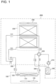
- Fig. 1 illustrates the configuration of an air-conditioning device according to Embodiment 1.
- the air-conditioning device is now explained as an example of the refrigeration cycle device including a heat exchanger in Embodiment 1.
- the air-conditioning device in Embodiment 1 includes an outdoor unit 200, an indoor unit 100, and two refrigerant pipes 300.
- the outdoor unit 200 includes a compressor 210, a four-way valve 220, and an outdoor heat exchanger 230.
- the indoor unit 100 includes an indoor heat exchanger 110 and an expansion valve 120.
- the compressor 210, the four-way valve 220, the outdoor heat exchanger 230, the indoor heat exchanger 110, and the expansion valve 120 are connected by the refrigerant pipes 300 to form a refrigerant circuit.
- one outdoor unit 200 and one indoor unit 100 are connected by pipes.
- the number of outdoor units 200 and the number of indoor units 100 to be connected to each other are not limited to this example.
- the indoor unit 100 includes an indoor air-sending device 130 in addition to the indoor heat exchanger 110 and the expansion valve 120.
- the expansion valve 120 that is an expansion device or other device reduces the pressure of refrigerant and expands the refrigerant.
- the expansion valve 120 adjusts its opening degree based on an instruction provided by a controller (not illustrated) or other device.
- the indoor heat exchanger 110 exchanges heat between refrigerant and air in a room that is an air-conditioned space. For example, during heating operation, the indoor heat exchanger 110 functions as a condenser, and condenses and liquefies the refrigerant.
- the indoor heat exchanger 110 functions as an evaporator, and evaporates and vaporizes the refrigerant.
- the indoor air-sending device 130 allows the air in the room to pass through the indoor heat exchanger 110, and supplies the air having passed through the indoor heat exchanger 110 to the room.
- the outdoor unit 200 in Embodiment 1 includes devices forming the refrigerant circuit, such as the compressor 210, the four-way valve 220, the outdoor heat exchanger 230, and an accumulator 240.
- the outdoor unit 200 includes an outdoor air-sending device 250.
- the compressor 210 compresses suctioned refrigerant and discharges the compressed refrigerant.
- the compressor 210 is, for example, a scroll compressor, a reciprocating compressor, or a vane compressor.
- the compressor 210 may allow an inverter circuit to optionally change the operational frequency to change the capacity of the compressor 210, although the configuration of the compressor 210 is not particularly limited.
- the four-way valve 220 that serves as a flow switching device is a valve to change the flow direction of refrigerant depending on cooling operation or heating operation.
- the four-way valve 220 connects the discharge side of the compressor 210 to the indoor heat exchanger 110, while connecting the suction side of the compressor 210 to the outdoor heat exchanger 230.
- the four-way valve 220 connects the discharge side of the compressor 210 to the outdoor heat exchanger 230, while connecting the suction side of the compressor 210 to the indoor heat exchanger 110.
- a case where the four-way valve 220 is used is described as an example, however, the flow switching device is not limited to this case.
- the accumulator 240 is installed on the suction side of the compressor 210.
- the accumulator 240 allows refrigerant in gas form (hereinafter, referred to as "gas refrigerant”) to pass through the accumulator 240, while accumulating refrigerant in liquid form (hereinafter, referred to as "liquid refrigerant”) in the accumulator 240.
- the outdoor heat exchanger 230 exchanges heat between refrigerant and outdoor air.
- Refrigerant is fluid to serve as a heat exchange medium for the outdoor heat exchanger 230.
- the outdoor heat exchanger 230 in Embodiment 1 functions as an evaporator during heating operation, and evaporates and vaporizes the refrigerant.
- the outdoor heat exchanger 230 functions as a condenser and a subcooling device, and condenses and liquefies the refrigerant to be subcooled.
- the outdoor heat exchanger 230 in Embodiment 1 includes heat exchangers 1, each of which includes a heat exchange portion 10 as will be described later.
- the heat exchanger 1 will be described later in detail.
- the outdoor air-sending device 250 is driven to allow air from the outside of the outdoor unit 200 to pass through the outdoor heat exchanger 230 to form a flow of air that flows out of the outdoor unit 200.
- each device in the air-conditioning device is described based on the flow of refrigerant.
- operation of each device in the refrigerant circuit during heating operation is described based on the flow of refrigerant.
- the solid arrows in Fig. 1 show the flow of refrigerant during heating operation.
- High-temperature high-pressure gas refrigerant, compressed by and discharged from the compressor 210 passes through the four-way valve 220, and then flows into the indoor heat exchanger 110. While passing through the indoor heat exchanger 110, the gas refrigerant exchanges heat with air in, for example, an air-conditioned space, and thereby condenses into liquid.
- the refrigerant having condensed into liquid passes through the expansion valve 120.
- the pressure of the refrigerant is reduced.
- the refrigerant exchanges heat with outdoor air delivered from the outdoor air-sending device 250, and thereby evaporates into gas.
- the gas refrigerant passes through the four-way valve 220 and the accumulator 240, and then is suctioned into the compressor 210 again.
- refrigerant of the air-conditioning device circulates, and thus the air-conditioning device performs heating-related air conditioning.
- Fig. 1 show the flow of refrigerant during cooling operation.
- High-temperature high-pressure gas refrigerant compressed by and discharged from the compressor 210, passes through the four-way valve 220, and then flows into the outdoor heat exchanger 230.
- the refrigerant passes through the outdoor heat exchanger 230, exchanges heat with outdoor air supplied by the outdoor air-sending device 250, and thereby condenses into liquid.
- the heat exchanger 1 will be described later.
- the liquid refrigerant passes through the expansion valve 120. When passing through the expansion valve 120, the subcooled refrigerant is reduced in pressure and brought into a two-phase gas-liquid state.
- This refrigerant reduced in pressure by the expansion valve 120 and brought into a two-phase gas-liquid state, then passes through the indoor heat exchanger 110.
- the refrigerant having exchanged heat with air in, for example, the air-conditioned space and thereby evaporated into gas, passes through the four-way valve 220, and is suctioned into the compressor 210 again.
- refrigerant of the air-conditioning device circulates, and thus the air-conditioning device performs cooling-related air conditioning.
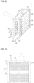
- Fig. 2 schematically illustrates the configuration of the heat exchanger 1 according to Embodiment 1.
- Fig. 3 is an explanatory view illustrating each part of the heat exchange portion 10 in the heat exchanger 1 according to Embodiment 1.
- the heat exchanger 1 according to Embodiment 1 is included in the outdoor heat exchanger 230.
- the heat exchanger 1 is not limited to being included in the outdoor heat exchanger 230, but may be included in the indoor heat exchanger 110.
- the heat exchanger 1 is a corrugated-fin and tube heat exchanger that is a parallel pipe heat exchanger.
- the heat exchanger 1 includes two distribution headers 11 (a distribution header 11A and a distribution header 11B) serving as a distribution merge portion, a turn-back header 13 serving as a turn-back portion, and the heat exchange portion 10 including a plurality of flat heat transfer tubes 14 and a plurality of corrugated fins 15.
- the two distribution headers 11 are located separately from the turn-back header 13 on either the left or right side.
- the turn-back header 13 is positioned on the right side, while the two distribution headers 11 are positioned on the left side relative to the turn-back header 13.
- the distribution headers 11 may be positioned on the right side, while the turn-back header 13 may be positioned on the left side.
- the up-down direction in Figs. 2 and 3 is defined as a height direction.
- the right-left direction in which the distribution headers 11 and the turn-back header 13 are located is defined as a horizontal direction.
- the direction in which the outdoor air-sending device 250 allows air to flow shown by the dotted arrow in Fig. 2 , is defined as a depth direction.
- the plurality of flat heat transfer tubes 14 are arranged in the height direction to be perpendicular to the distribution headers 11 and the turn-back header 13 with the flat surfaces of the flat heat transfer tubes 14 facing parallel to each other.
- groups of the plurality of flat heat transfer tubes 14 are arranged in two rows in the depth direction that is the front-rear direction. One row of a group of the flat heat transfer tubes 14 is connected to a single distribution header 11.
- Each of the flat heat transfer tubes 14 serves as a flow passage of refrigerant.
- the number of the flat heat transfer tubes 14 is equal in each row group.
- the number of the flat heat transfer tubes 14 is equal as described above, so that the flat heat transfer tubes 14 are equally spaced from each other, thereby not to interfere with the passage of air.
- the heat exchanger 1 can be easily manufactured.
- One of the two rows of the flat heat transfer tubes 14, arranged on the airflow upstream side relative to the direction in which air passes through the heat exchanger 1, is defined as "airflow upstream side row,” while the other row arranged on the airflow downstream side is defined as “airflow downstream side row.”
- the distribution headers 11 that are devices serving as a distribution merge portion are connected by pipes to other devices that make up the refrigeration cycle device.
- Each of the distribution headers 11 is a pipe serving as a refrigerant distributor to allow refrigerant to flow into and out of the heat exchanger 1, and divide and distribute the refrigerant or merge refrigerant flows.
- the refrigerant is fluid serving as a heat exchange medium. While the distribution headers 11 have a circular cylindrical shape, the distribution headers 11 are not limited to having a particular shape.
- the distribution headers 11 respectively include refrigerant inlet/outlet pipes 12 (a refrigerant inlet/outlet pipe 12A and a refrigerant inlet/outlet pipe 12B) through which refrigerant flows in from and out to the outside.
- the heat exchanger 1 serves as a condenser
- refrigerant flows into the heat exchanger 1 through the refrigerant inlet/outlet pipe 12A, and flows out through the refrigerant inlet/outlet pipe 12B.
- the heat exchanger 1 serves as an evaporator
- refrigerant flows into the heat exchanger 1 through the refrigerant inlet/outlet pipe 12B, and flows out through the refrigerant inlet/outlet pipe 12A.
- the interior of the distribution header 11 is partitioned by a plurality of baffles (not illustrated) into a plurality of spaces.
- the interior of the distribution header 11 is divided into a plurality of spaces, and thus the heat exchanger 1 can be divided into a plurality of regions.
- the region refers to a group of the flat heat transfer tubes 14, in each of which refrigerant flows in the same direction.
- the baffles partition the interior of the distribution header 11, so that a plurality of the flat heat transfer tubes 14 can be grouped into a single region.
- the regions in Embodiment 1 will be described later.
- Connection pipes 16 connect the spaces, separated from each other inside the distribution header 11, from the outside. Each of the connection pipes 16 not only connects the spaces inside the distribution header 11 on a one-to-one basis, but can also branch off on one side to connect one of the spaces inside the distribution header 11 to a plurality of the spaces.
- the turn-back header 13 serves as a bridge configured to merge refrigerant flows from one row of a group of the flat heat transfer tubes 14, and then divide the refrigerant into the other row of a group of the flat heat transfer tubes 14 to allow the refrigerant to flow out.
- baffles (not illustrated) are also installed at least at positions corresponding to the positions of the baffles in the distribution headers 11 to divide the interior of the turn-back header 13 into a plurality of spaces.
- baffles may be installed inside the turn-back header 13 corresponding to the respective flat heat transfer tubes 14.
- the interior of the turn-back header 13 may be divided into spaces in a one-to-one correspondence with their respective flat heat transfer tubes 14.
- the main heat exchange portions 10A of the airflow upstream side row and the airflow downstream side row will be described later.
- refrigerant flows are not merged, or the refrigerant is not divided into flows.
- the flat heat transfer tubes 14 in the heat exchange portion 10 of the airflow upstream side row are brought into one-to-one correspondence with the flat heat transfer tubes 14 in the heat exchange portion 10 of the airflow downstream side row.
- individual connection pipes or the like can be used to connect the flat heat transfer tubes 14 corresponding to each other.
- Each of the flat heat transfer tubes 14 has an elongated shape in cross-section in which the outer surface on the longitudinal side of the elongated shape along the depth direction that is an air flow direction is flat, while the outer surface on the relatively short side of the elongated shape perpendicular to the longitudinal direction is curved.
- Each of the flat heat transfer tubes 14 in Embodiment 1 is a multi-hole flat heat transfer tube having a plurality of holes serving as a flow passage of refrigerant inside the tube. In Embodiment 1, since the holes of the flat heat transfer tubes 14 serve as a flow passage extending between the distribution headers 11 and the turn-back header 13, these holes are formed in the horizontal direction.
- each of the flat heat transfer tubes 14 is inserted into an insertion hole (not illustrated) formed on the distribution header 11 and an insertion hole (not illustrated) formed on the turn-back header 13 to be brazed and joined to the distribution header 11 and the turn-back header 13.
- the brazing material to be used include an aluminum-containing brazing material. With this brazing, the inside of each of the flat heat transfer tubes 14 communicates with the distribution header 11 and the turn-back header 13.
- the corrugated fins 15 are located between the opposite flat surfaces of the flat heat transfer tubes 14 aligned in a row.
- the corrugated fins 15 are located to increase the heat transfer area between refrigerant and outside air.
- Each of the corrugated fins 15 is formed by corrugating a plate material into a wavy shape in which the plate material is folded in a zigzag pattern with a series of alternate crest folds and valley folds.
- the folded portions of protrusions and recesses formed into a wavy shape are the peaks of the wavy shape.
- the peaks of the corrugated fins 15 are arranged along the height direction.
- Each of the corrugated fins 15 is in surface contact at the peaks of the wavy shape with the flat surfaces of the flat heat transfer tubes 14.
- the contact portions are brazed and joined to each other by using a brazing material.
- the plate material for the corrugated fins 15 is made of, for example, aluminum alloy.
- the surface of the plate material is coated with a layer of brazing material.
- the coating layer of brazing material is, for example, based on a brazing material containing aluminum silicon-based aluminum.
- the baffles installed inside the distribution headers 11 and the turn-back header 13 divide the flat heat transfer tubes 14 of the airflow upstream side row into regions, and divide the flat heat transfer tubes 14 of the airflow downstream side row into regions.
- the regions are the main heat exchange portion 10A, a first auxiliary heat exchange portion 10B, and a second auxiliary heat exchange portion 10C.
- the uppermost region is defined as the main heat exchange portion 10A.
- the region lower than the main heat exchange portion 10A is defined as the first auxiliary heat exchange portion 10B.
- the region lower than the first auxiliary heat exchange portion 10B is defined as the second auxiliary heat exchange portion 10C.
- the number of the flat heat transfer tubes 14 grouped together in each region of the heat exchanger 1 in Embodiment 1 has the relationship expressed as "the main heat exchange portion 10A>the first auxiliary heat exchange portion 10B ⁇ the second auxiliary heat exchange portion 10C.”
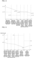
- Fig. 4 schematically illustrates variations in the temperatures of air and refrigerant in the heat exchanger 1 according to Embodiment 1 when the heat exchanger 1 serves as a condenser.
- the solid line shows the temperature of refrigerant, while the dotted line shows the temperature of air (the same applies in Figs. 5 and 6 ).
- the arrows illustrated in the heat exchange portion 10 show the flow of refrigerant in the heat exchange portion 10 when the heat exchanger 1 serves as a condenser.
- refrigerant flows through the refrigerant inlet/outlet pipe 12A into the distribution header 11A.
- the refrigerant having flowed into the distribution header 11A passes through the flat heat transfer tubes 14 belonging to the main heat exchange portion 10A of the airflow downstream side row.
- the flat heat transfer tubes 14 exchange heat between refrigerant passing through the inside of the tubes and outside air passing outside the tubes. At this time, while passing through the flat heat transfer tubes 14, the refrigerant transfers heat to the outside air.
- the heat exchanger 1 serves as a condenser, refrigerant transfers heat to the outside air while passing through the flat heat transfer tubes 14, in all the regions in the same manner.
- the refrigerant is turned back in the turn-back header 13, and passes through the flat heat transfer tubes 14 belonging to the main heat exchange portion 10A of the airflow upstream side row.
- the refrigerant having passed through the flat heat transfer tubes 14 of the airflow upstream side row and having exchanged heat with air, flows into the distribution header 11B.
- the refrigerant having flowed into the distribution header 11B passes through the connection pipes 16 and flows into other spaces in the distribution header 11B.
- the refrigerant passes through the flat heat transfer tubes 14 belonging to the first auxiliary heat exchange portion 10B of the airflow upstream side row, is turned back in the turn-back header 13, passes through the first auxiliary heat exchange portion 10B of the airflow downstream side row, and then flows into the distribution header 11A.
- the refrigerant having flowed into the distribution header 11A passes through the connection pipes 16 and flows into other spaces in the distribution header 11A. Then, the refrigerant passes through the flat heat transfer tubes 14 belonging to the second auxiliary heat exchange portion 10C of the airflow downstream side row, is turned back in the turn-back header 13, passes through the second auxiliary heat exchange portion 10C of the airflow upstream side row, and then flows into the distribution header 11B.
- the refrigerant, having flowed in the order described and condensed flows out through the refrigerant inlet/outlet pipe 12B. Therefore, when the heat exchanger 1 in Embodiment 1 serves as a condenser, refrigerant that flows in the main heat exchange portions 10A forms a counter flow to the flow of air.
- the counter flow refers to a flow in which refrigerant on the downstream side of the refrigerant flow and air on the upstream side of the air flow exchange heat between them, and also refrigerant on the upstream side of the refrigerant flow and air on the downstream side of the air flow exchange heat between them.
- Fig. 5 schematically illustrates variations in the temperatures of air and refrigerant in the heat exchanger 1 according to Embodiment 1 when the heat exchanger 1 serves as an evaporator.
- refrigerant flows through the refrigerant inlet/outlet pipe 12B into the distribution header 11B.
- the refrigerant having flowed into the distribution header 11B passes through the flat heat transfer tubes 14 belonging to the second auxiliary heat exchange portion 10C of the airflow upstream side row.
- the flat heat transfer tubes 14 exchange heat between refrigerant passing through the inside of the tubes and outside air passing outside the tubes.
- the refrigerant receives heat from the outside air.
- refrigerant receives heat from the outside air while passing through the flat heat transfer tubes 14, in all the regions in the same manner.
- the refrigerant is turned back in the turn-back header 13, and passes through the flat heat transfer tubes 14 belonging to the second auxiliary heat exchange portion 10C of the airflow downstream side row.
- the refrigerant having passed through the flat heat transfer tubes 14 of the airflow downstream side row and having exchanged heat with air, flows into the distribution header 11A.
- the refrigerant having flowed into the distribution header 11A passes through the connection pipes 16 and flows into other spaces in the distribution header 11A.
- the refrigerant passes through the flat heat transfer tubes 14 belonging to the first auxiliary heat exchange portion 10B of the airflow downstream side row, is turned back in the turn-back header 13, passes through the first auxiliary heat exchange portion 10B of the airflow upstream side row, and then flows into the distribution header 11B.
- the refrigerant having flowed into the distribution header 11B passes through the connection pipes 16 and flows into other spaces in the distribution header 11B. Then, the refrigerant passes through the flat heat transfer tubes 14 belonging to the main heat exchange portion 10A of the airflow upstream side row, is turned back in the turn-back header 13, passes through the main heat exchange portion 10A of the airflow downstream side row, and then flows into the distribution header 11A.
- the refrigerant, having flowed in the order described and condensed flows out through the refrigerant inlet/outlet pipe 12A. Therefore, when the heat exchanger 1 in Embodiment 1 serves as an evaporator, refrigerant that flows in the main heat exchange portions 10A forms a parallel flow to the flow of air.
- the parallel flow refers to a flow in which refrigerant on the upstream side of the refrigerant flow and air on the upstream side of the air flow exchange heat between them, and also refrigerant on the downstream side of the refrigerant flow and air on the downstream side of the air flow exchange heat between them.
- the refrigerant passing through the main heat exchange portion 10A has a sufficient temperature difference from the air passing through the heat exchanger 1 to effectively exchange heat between them. This prevents the heat exchanger 1 from degrading its heat exchange performance when the heat exchanger 1 serves as an evaporator. Thus, the heat exchanger 1 can maintain its evaporator performance.
- the heat exchanger 1 when the heat exchanger 1 serves as a condenser, refrigerant flows in such a manner that a flow of refrigerant in the main heat exchange portion 10A, and a flow of air passing through the heat exchanger 1 form a counter flow. Due to this configuration, the heat exchanger 1 can maintain a sufficient temperature difference between refrigerant and air to effectively exchange heat between them throughout the entire refrigerant flow passage, and can consequently improve the heat transfer performance of the heat exchanger 1.
- the heat exchanger 1 serves as an evaporator
- a flow of refrigerant in the main heat exchange portion 10A, and a flow of air passing through the heat exchanger 1 form a parallel flow.
- this causes pressure loss of refrigerant in the second auxiliary heat exchange portion 10C, and refrigerant whose temperature has decreased flows into the main heat exchange portion 10A. Due to this configuration, the refrigerant passing through the main heat exchange portion 10A has a sufficient temperature difference from the air passing through the heat exchanger 1 to effectively exchange heat between them.
- the heat exchanger 1 can maintain its evaporator performance.
- the number of the flat heat transfer tubes 14 is equal in both two rows, and consequently air can pass through the flat heat transfer tubes 14 that are equally spaced from each other.
- the turn-back header 13 refrigerant flows are not merged, or the refrigerant is not divided into flows, and one row of the flat heat transfer tubes 14 are brought into one-to-one correspondence with another row of the flat heat transfer tubes 14. This can prevent an uneven flow of refrigerant in the turn-back header 13.
- Fig. 6 schematically illustrates variations in the temperatures of air and refrigerant in the heat exchanger 1 according to Embodiment 2 when the heat exchanger 1 serves as an evaporator.
- the air-conditioning device and the heat exchanger 1 in Embodiment 2 have identical configurations to the air-conditioning device and the heat exchanger 1 described in Embodiment 1.
- the number of the flat heat transfer tubes 14 grouped into each region of the heat exchanger 1 in Embodiment 2 particularly has a relationship expressed as "the main heat exchange portion 10A>the first auxiliary heat exchange portion 10B>the second auxiliary heat exchange portion 10C.”
- the heat exchanger 1 serves as an evaporator
- refrigerant flows through the refrigerant inlet/outlet pipe 12B into the distribution header 11B, and then passes through the flat heat transfer tubes 14 belonging to the second auxiliary heat exchange portion 10C of the airflow upstream side row, that is the region at the lowermost position of the heat exchanger 1.
- the air-conditioning device allows refrigerant to circulate in the refrigerant circuit such that the refrigerant flows into the second auxiliary heat exchange portion 10C of the airflow upstream side row with a temperature of the refrigerant higher than the temperature of air that passes through the heat exchange portion 10 of the airflow upstream side row.
- the refrigerant passing through the second auxiliary heat exchange portion 10C of the airflow upstream side row at the lowermost position has a temperature higher than the temperature of air. This prevents drain water accumulating at the bottom of the heat exchanger 1 to be used as the outdoor heat exchanger 230 in the outdoor unit 200 from freezing. With this configuration, the passage of air through the heat exchanger 1 is prevented from being interfered with by root ice or the like, and the heat exchange efficiency can be maintained.
- Fig. 7 is an explanatory view illustrating allocation of flat heat transfer tubes 14 in the heat exchanger 1 according to Embodiment 3.
- the flat heat transfer tubes 14 belonging to the main heat exchange portion 10A are further divided into a plurality of subgroups with different distribution paths by baffles in the distribution headers 11 and the turn-back header 13.
- the number of the flat heat transfer tubes 14 may not be equal in each of the subgroups, but may differ between the subgroups.
- an air-sending device includes a side flow fan with its rotational shaft extending in the same direction as the direction in which air passes through the heat exchanger 1.
- the subgroups are arranged at least in such a manner that the number of the flat heat transfer tubes 14 in the nearest subgroup from the rotation center of the air-sending device is fewer than those in the other subgroups.
- a fewer number of the flat heat transfer tubes 14 are allocated near the rotation center, while a larger amount of refrigerant flows in the flat heat transfer tubes 14 with a higher thermal load, so that the heat exchanger 1 can improve its heat exchange performance.
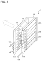
- Fig. 8 schematically illustrates the configuration of the heat exchanger 1 according to Embodiment 4.
- the same components as those described in Embodiment 1 are denoted by the same reference numerals as those illustrated in Fig. 2 .
- the subgroups of the flat heat transfer tubes 14 belonging to the main heat exchange portion 10A of the airflow upstream side row are connected to each other by using a layered distributor 17, instead of using the distribution header 11B.
- the layered distributor 17 distributes refrigerant flowing therein after the refrigerant has passed through the first auxiliary heat exchange portion 10B of the airflow upstream side row, the distribution header 11B, and the connection pipes 16.
- the layered distributor 17 merges refrigerant flows having passed through the main heat exchange portion 10A.
- Fig. 9 illustrates an example of the configuration of the layered distributor 17 according to Embodiment 4.
- the layered distributor 17 is manufactured by stacking a plurality of plates 17A on one another, that are a plurality of plate-like parts including through holes or through grooves serving as a flow passage.
- the plates 17A include flow passage grooves 17B and flow passage holes 17C.
- the flow passage grooves 17B allow refrigerant to pass therethrough.
- the flow passage holes 17C are through holes communicating with the adjacent plates 17A to allow the refrigerant to pass therethrough.
- the layered distributor 17 is not limited to having the configuration illustrated in Fig. 9 .
- the large region of main heat exchange portion 10A uses the layered distributor 17 to distribute refrigerant, and can thereby minimize uneven refrigerant distribution, such as gas-phase refrigerant of the two-phase gas-liquid refrigerant passing excessively through the flat heat transfer tubes 14 arranged on the upper side. This can improve the efficiency in heat exchange.
- the heat exchangers 1 are used as the outdoor heat exchanger 230 of the outdoor unit 200, however, use of the heat exchangers 1 is not limited to this example.
- the heat exchangers 1 may be used as the indoor heat exchanger 110 of the indoor unit 100, or may be used as both the outdoor heat exchanger 230 and the indoor heat exchanger 110.
- the air-conditioning device has been explained.
- the heat exchanger 1 is also applicable to other refrigeration cycle devices, such as a refrigerator, a freezer, or a water heater.
- the heat exchanger 1 is described as a corrugated-fin and tube heat exchanger including the heat exchange portion 10 using the flat heat transfer tubes 14.
- the heat exchanger 1 may include the heat exchange portion 10 configured to exchange heat by using, for example, circular heat transfer tubes.
Landscapes
- Engineering & Computer Science (AREA)
- Physics & Mathematics (AREA)
- Thermal Sciences (AREA)
- Mechanical Engineering (AREA)
- General Engineering & Computer Science (AREA)
- Heat-Exchange Devices With Radiators And Conduit Assemblies (AREA)
Abstract
Description
- The present technology relates to a heat exchanger and a refrigeration cycle device. Particularly, the present technology relates to a heat exchanger that exchanges heat while distributing refrigerant.
- In recent years, a heat exchanger for an air-conditioning device uses heat transfer tubes that have become increasingly thinner to reduce the amount of refrigerant and improve performance of the heat exchanger. While using the heat transfer tubes that have become increasingly thinner, the heat exchanger has an increased number of passes (the number of branches) to minimize the increase in pressure loss of refrigerant. Heat exchangers using a header refrigerant distributor have been developed to cope with this multi-branch distribution (see, for example, Patent Literature 1).
- Patent Literature 1:
Japanese Patent Publication No. 5679084 - The header refrigerant distributor unevenly distributes gas refrigerant with a larger amount on the upper side due to an inertial force. Due to this uneven distribution, when operating as an evaporator, the heat exchanger tends to exhibit degraded evaporator performance. To prevent the evaporator performance from being degraded, when the heat exchanger operates as an evaporator, a counter flow is formed such that refrigerant flows in a direction opposite to the airflow direction in a section of the heat exchanger with a greater number of tube layers than in the other sections. In contrast, when the heat exchanger operates as a condenser, refrigerant flows in the heat exchanger in a direction reverse to the refrigerant flow direction when the heat exchanger operates as an evaporator. Thus, when the heat exchanger operates as a condenser, a parallel flow is formed such that refrigerant flows in a direction parallel to the airflow direction. Compared to the counter flow, the parallel flow cannot ensure a sufficient temperature difference between refrigerant and air, and this results in degradation in condensation performance of the heat exchanger.
- The present disclosure has been achieved to solve the above problems, and it is an object of the present disclosure to provide a heat exchanger that can improve its heat exchange performance, and a refrigeration cycle device.
- A heat exchanger according to one embodiment of the present disclosure includes: a heat exchange portion in which a plurality of heat transfer tubes, in which refrigerant flows, are arranged in a height direction, the plurality of heat transfer tubes being configured to exchange heat between the refrigerant and air; a turn-back portion to which one end of each of the plurality of heat transfer tube is connected and which is configured to allow the refrigerant to flow between two rows of heat exchange portions arranged in an airflow direction, one of the two rows of heat exchange portions being the heat exchange portion and arranged on an airflow upstream side, an other of the two rows of heat exchange portions being the heat exchange portion and arranged on an airflow downstream side; and a plurality of distribution merge portions to each of which the other end of the heat transfer tube of the heat exchange portion of each row is connected, and which is configured to distribute the refrigerant to the heat transfer tube or merge refrigerant flows from the heat exchange portions, the plurality of heat transfer tubes of the heat exchange portion being grouped into, in order from an upper side in the height direction, a main heat exchange portion, a first auxiliary heat exchange portion having fewer number of the heat transfer tubes than those of the main heat exchange portion, and a second auxiliary heat exchange portion having fewer number of the heat transfer tubes than those of the first auxiliary heat exchange portion, and being configured to, when the heat exchanger serves as a condenser, allow the refrigerant to flow through the heat exchanger in order of the main heat exchange portion of the airflow downstream side row, the main heat exchange portion of the airflow upstream side row, the first auxiliary heat exchange portion of the airflow upstream side row, the first auxiliary heat exchange portion of the airflow downstream side row, the second auxiliary heat exchange portion of the airflow downstream side row, and the second auxiliary heat exchange portion of the airflow upstream side row, and allow the refrigerant to flow out of the heat exchanger.
- A refrigeration cycle device according to another embodiment of the present disclosure includes the heat exchanger described above to serve at least as a condenser.
- According to one embodiment of the present disclosure, when the heat exchanger serves as a condenser, a flow of refrigerant in the main heat exchange portion and a flow of air passing through the heat exchanger form a counter flow to exchange heat between the upstream side of the refrigerant in the main heat exchange portion and the downstream side of the air, and exchange heat between the downstream side of the refrigerant in the main heat exchange portion and the upstream side of the air. Due to this configuration, the heat exchanger can maintain a sufficient temperature difference between refrigerant and air to effectively exchange heat between them throughout the entire refrigerant flow passage, and can consequently improve the heat transfer performance of the heat exchanger.
-
- [
Fig. 1] Fig. 1 illustrates the configuration of an air-conditioning device according toEmbodiment 1. - [
Fig. 2] Fig. 2 schematically illustrates the configuration of aheat exchanger 1 according toEmbodiment 1. - [
Fig. 3] Fig. 3 is an explanatory view illustrating each part of aheat exchange portion 10 in theheat exchanger 1 according toEmbodiment 1. - [
Fig. 4] Fig. 4 schematically illustrates variations in the temperatures of air and refrigerant in theheat exchanger 1 according toEmbodiment 1 when theheat exchanger 1 serves as a condenser. - [
Fig. 5] Fig. 5 schematically illustrates variations in the temperatures of air and refrigerant in theheat exchanger 1 according toEmbodiment 1 when theheat exchanger 1 serves as an evaporator. - [
Fig. 6] Fig. 6 schematically illustrates variations in the temperatures of air and refrigerant in theheat exchanger 1 according toEmbodiment 2 when theheat exchanger 1 serves as an evaporator. - [
Fig. 7] Fig. 7 is an explanatory view illustrating allocation of flatheat transfer tubes 14 in theheat exchanger 1 according toEmbodiment 3. - [
Fig. 8] Fig. 8 schematically illustrates the configuration of theheat exchanger 1 according toEmbodiment 4. - [
Fig. 9] Fig. 9 illustrates an example of the configuration of alayered distributor 17 according toEmbodiment 4. - Hereinafter, a heat exchanger and a refrigeration cycle device according to the embodiments will be described with reference to the drawings and the like. In the drawings below, like reference signs denote the like or corresponding components, and are common throughout the entire descriptions of the embodiments described below. In addition, the relationship of sizes of the constituent parts in the drawings may differ from that of actual ones. Furthermore, in the cross-sectional view, hatching is omitted in some of the drawings and devices in view of visibility. The forms of the constituent elements represented throughout the entire specification are merely examples, and do not intend to limit the constituent elements to the forms described in the specification. In particular, the combination of constituent elements is not limited to only the combination in each embodiment, and the constituent elements described in one embodiment can be applied to another embodiment. The upper side in the drawings is described as "up," while the lower side in the drawings is described as "down." Furthermore, the level of the pressure and temperature is not particularly determined in relation to an absolute value, but is determined relative to the conditions or operation of a device or the like. When it is not necessary to distinguish or specify a plurality of devices of the same type that are distinguished from each other by subscripts, the subscripts may be omitted.
-
Fig. 1 illustrates the configuration of an air-conditioning device according toEmbodiment 1. The air-conditioning device is now explained as an example of the refrigeration cycle device including a heat exchanger inEmbodiment 1. - As illustrated in
Fig. 1 , the air-conditioning device inEmbodiment 1 includes anoutdoor unit 200, anindoor unit 100, and tworefrigerant pipes 300. Theoutdoor unit 200 includes acompressor 210, a four-way valve 220, and anoutdoor heat exchanger 230. Theindoor unit 100 includes anindoor heat exchanger 110 and anexpansion valve 120. Thecompressor 210, the four-way valve 220, theoutdoor heat exchanger 230, theindoor heat exchanger 110, and theexpansion valve 120 are connected by therefrigerant pipes 300 to form a refrigerant circuit. In the air-conditioning device in Embodiment 1, oneoutdoor unit 200 and oneindoor unit 100 are connected by pipes. However, the number ofoutdoor units 200 and the number ofindoor units 100 to be connected to each other are not limited to this example. - The
indoor unit 100 includes an indoor air-sending device 130 in addition to theindoor heat exchanger 110 and theexpansion valve 120. Theexpansion valve 120 that is an expansion device or other device reduces the pressure of refrigerant and expands the refrigerant. When theexpansion valve 120 is made up of, for example, an electronic expansion valve, theexpansion valve 120 adjusts its opening degree based on an instruction provided by a controller (not illustrated) or other device. Theindoor heat exchanger 110 exchanges heat between refrigerant and air in a room that is an air-conditioned space. For example, during heating operation, theindoor heat exchanger 110 functions as a condenser, and condenses and liquefies the refrigerant. During cooling operation, theindoor heat exchanger 110 functions as an evaporator, and evaporates and vaporizes the refrigerant. The indoor air-sending device 130 allows the air in the room to pass through theindoor heat exchanger 110, and supplies the air having passed through theindoor heat exchanger 110 to the room. - The
outdoor unit 200 inEmbodiment 1 includes devices forming the refrigerant circuit, such as thecompressor 210, the four-way valve 220, theoutdoor heat exchanger 230, and anaccumulator 240. Theoutdoor unit 200 includes an outdoor air-sending device 250. Thecompressor 210 compresses suctioned refrigerant and discharges the compressed refrigerant. Thecompressor 210 is, for example, a scroll compressor, a reciprocating compressor, or a vane compressor. For example, thecompressor 210 may allow an inverter circuit to optionally change the operational frequency to change the capacity of thecompressor 210, although the configuration of thecompressor 210 is not particularly limited. - For example, the four-
way valve 220 that serves as a flow switching device is a valve to change the flow direction of refrigerant depending on cooling operation or heating operation. When heating operation is performed, the four-way valve 220 connects the discharge side of thecompressor 210 to theindoor heat exchanger 110, while connecting the suction side of thecompressor 210 to theoutdoor heat exchanger 230. When cooling operation is performed, the four-way valve 220 connects the discharge side of thecompressor 210 to theoutdoor heat exchanger 230, while connecting the suction side of thecompressor 210 to theindoor heat exchanger 110. A case where the four-way valve 220 is used is described as an example, however, the flow switching device is not limited to this case. For example, a plurality of two-way valves or other valves may be combined to form the flow switching device. Theaccumulator 240 is installed on the suction side of thecompressor 210. Theaccumulator 240 allows refrigerant in gas form (hereinafter, referred to as "gas refrigerant") to pass through theaccumulator 240, while accumulating refrigerant in liquid form (hereinafter, referred to as "liquid refrigerant") in theaccumulator 240. - The
outdoor heat exchanger 230 exchanges heat between refrigerant and outdoor air. Refrigerant is fluid to serve as a heat exchange medium for theoutdoor heat exchanger 230. Theoutdoor heat exchanger 230 inEmbodiment 1 functions as an evaporator during heating operation, and evaporates and vaporizes the refrigerant. In contrast, during cooling operation, theoutdoor heat exchanger 230 functions as a condenser and a subcooling device, and condenses and liquefies the refrigerant to be subcooled. Theoutdoor heat exchanger 230 inEmbodiment 1 includesheat exchangers 1, each of which includes aheat exchange portion 10 as will be described later. Theheat exchanger 1 will be described later in detail. The outdoor air-sendingdevice 250 is driven to allow air from the outside of theoutdoor unit 200 to pass through theoutdoor heat exchanger 230 to form a flow of air that flows out of theoutdoor unit 200. - Next, operation of each device in the air-conditioning device is described based on the flow of refrigerant. First, operation of each device in the refrigerant circuit during heating operation is described based on the flow of refrigerant. The solid arrows in
Fig. 1 show the flow of refrigerant during heating operation. High-temperature high-pressure gas refrigerant, compressed by and discharged from thecompressor 210, passes through the four-way valve 220, and then flows into theindoor heat exchanger 110. While passing through theindoor heat exchanger 110, the gas refrigerant exchanges heat with air in, for example, an air-conditioned space, and thereby condenses into liquid. The refrigerant having condensed into liquid passes through theexpansion valve 120. When the refrigerant passes through theexpansion valve 120, the pressure of the refrigerant is reduced. The refrigerant, reduced in pressure by theexpansion valve 120 and brought into a two-phase gas-liquid state, passes through theoutdoor heat exchanger 230. In theoutdoor heat exchanger 230, the refrigerant exchanges heat with outdoor air delivered from the outdoor air-sendingdevice 250, and thereby evaporates into gas. The gas refrigerant passes through the four-way valve 220 and theaccumulator 240, and then is suctioned into thecompressor 210 again. In the manner as described above, refrigerant of the air-conditioning device circulates, and thus the air-conditioning device performs heating-related air conditioning. - Next, cooling operation is described. The dotted arrows in
Fig. 1 show the flow of refrigerant during cooling operation. High-temperature high-pressure gas refrigerant, compressed by and discharged from thecompressor 210, passes through the four-way valve 220, and then flows into theoutdoor heat exchanger 230. The refrigerant passes through theoutdoor heat exchanger 230, exchanges heat with outdoor air supplied by the outdoor air-sendingdevice 250, and thereby condenses into liquid. Theheat exchanger 1 will be described later. The liquid refrigerant passes through theexpansion valve 120. When passing through theexpansion valve 120, the subcooled refrigerant is reduced in pressure and brought into a two-phase gas-liquid state. This refrigerant, reduced in pressure by theexpansion valve 120 and brought into a two-phase gas-liquid state, then passes through theindoor heat exchanger 110. In theindoor heat exchanger 110, the refrigerant, having exchanged heat with air in, for example, the air-conditioned space and thereby evaporated into gas, passes through the four-way valve 220, and is suctioned into thecompressor 210 again. In the manner as described above, refrigerant of the air-conditioning device circulates, and thus the air-conditioning device performs cooling-related air conditioning. -
Fig. 2 schematically illustrates the configuration of theheat exchanger 1 according toEmbodiment 1.Fig. 3 is an explanatory view illustrating each part of theheat exchange portion 10 in theheat exchanger 1 according toEmbodiment 1. Theheat exchanger 1 according toEmbodiment 1 is included in theoutdoor heat exchanger 230. However, theheat exchanger 1 is not limited to being included in theoutdoor heat exchanger 230, but may be included in theindoor heat exchanger 110. Theheat exchanger 1 is a corrugated-fin and tube heat exchanger that is a parallel pipe heat exchanger. Theheat exchanger 1 includes two distribution headers 11 (adistribution header 11A and adistribution header 11B) serving as a distribution merge portion, a turn-back header 13 serving as a turn-back portion, and theheat exchange portion 10 including a plurality of flatheat transfer tubes 14 and a plurality ofcorrugated fins 15. - In the
heat exchanger 1 inEmbodiment 1, the twodistribution headers 11 are located separately from the turn-back header 13 on either the left or right side. InFig. 3 , the turn-back header 13 is positioned on the right side, while the twodistribution headers 11 are positioned on the left side relative to the turn-back header 13. However, thedistribution headers 11 may be positioned on the right side, while the turn-back header 13 may be positioned on the left side. In the explanations below, the up-down direction inFigs. 2 and 3 is defined as a height direction. The right-left direction in which thedistribution headers 11 and the turn-back header 13 are located is defined as a horizontal direction. The direction in which the outdoor air-sendingdevice 250 allows air to flow, shown by the dotted arrow inFig. 2 , is defined as a depth direction. - As illustrated in
Fig. 3 , between the twodistribution headers 11 and the turn-back header 13, the plurality of flatheat transfer tubes 14 are arranged in the height direction to be perpendicular to thedistribution headers 11 and the turn-back header 13 with the flat surfaces of the flatheat transfer tubes 14 facing parallel to each other. In theheat exchanger 1 inEmbodiment 1, groups of the plurality of flatheat transfer tubes 14 are arranged in two rows in the depth direction that is the front-rear direction. One row of a group of the flatheat transfer tubes 14 is connected to asingle distribution header 11. Each of the flatheat transfer tubes 14 serves as a flow passage of refrigerant. In the heat exchanger inEmbodiment 1, the number of the flatheat transfer tubes 14 is equal in each row group. The number of the flatheat transfer tubes 14 is equal as described above, so that the flatheat transfer tubes 14 are equally spaced from each other, thereby not to interfere with the passage of air. In addition, theheat exchanger 1 can be easily manufactured. One of the two rows of the flatheat transfer tubes 14, arranged on the airflow upstream side relative to the direction in which air passes through theheat exchanger 1, is defined as "airflow upstream side row," while the other row arranged on the airflow downstream side is defined as "airflow downstream side row." An example in which the flatheat transfer tubes 14 are arranged in two rows is described below. - The
distribution headers 11 that are devices serving as a distribution merge portion are connected by pipes to other devices that make up the refrigeration cycle device. Each of thedistribution headers 11 is a pipe serving as a refrigerant distributor to allow refrigerant to flow into and out of theheat exchanger 1, and divide and distribute the refrigerant or merge refrigerant flows. The refrigerant is fluid serving as a heat exchange medium. While thedistribution headers 11 have a circular cylindrical shape, thedistribution headers 11 are not limited to having a particular shape. Thedistribution headers 11 respectively include refrigerant inlet/outlet pipes 12 (a refrigerant inlet/outlet pipe 12A and a refrigerant inlet/outlet pipe 12B) through which refrigerant flows in from and out to the outside. When theheat exchanger 1 serves as a condenser, refrigerant flows into theheat exchanger 1 through the refrigerant inlet/outlet pipe 12A, and flows out through the refrigerant inlet/outlet pipe 12B. In contrast, when theheat exchanger 1 serves as an evaporator, refrigerant flows into theheat exchanger 1 through the refrigerant inlet/outlet pipe 12B, and flows out through the refrigerant inlet/outlet pipe 12A. The interior of thedistribution header 11 is partitioned by a plurality of baffles (not illustrated) into a plurality of spaces. The interior of thedistribution header 11 is divided into a plurality of spaces, and thus theheat exchanger 1 can be divided into a plurality of regions. The region refers to a group of the flatheat transfer tubes 14, in each of which refrigerant flows in the same direction. The baffles partition the interior of thedistribution header 11, so that a plurality of the flatheat transfer tubes 14 can be grouped into a single region. The regions inEmbodiment 1 will be described later.Connection pipes 16 connect the spaces, separated from each other inside thedistribution header 11, from the outside. Each of theconnection pipes 16 not only connects the spaces inside thedistribution header 11 on a one-to-one basis, but can also branch off on one side to connect one of the spaces inside thedistribution header 11 to a plurality of the spaces. - The turn-
back header 13 serves as a bridge configured to merge refrigerant flows from one row of a group of the flatheat transfer tubes 14, and then divide the refrigerant into the other row of a group of the flatheat transfer tubes 14 to allow the refrigerant to flow out. In the turn-back header 13, baffles (not illustrated) are also installed at least at positions corresponding to the positions of the baffles in thedistribution headers 11 to divide the interior of the turn-back header 13 into a plurality of spaces. For example, baffles may be installed inside the turn-back header 13 corresponding to the respective flatheat transfer tubes 14. Particularly, between the mainheat exchange portion 10A of the airflow upstream side row and the mainheat exchange portion 10A of the airflow downstream side row, the interior of the turn-back header 13 may be divided into spaces in a one-to-one correspondence with their respective flatheat transfer tubes 14. The mainheat exchange portions 10A of the airflow upstream side row and the airflow downstream side row will be described later. In this case, in the turn-back header 13, refrigerant flows are not merged, or the refrigerant is not divided into flows. There is a case where the flatheat transfer tubes 14 in theheat exchange portion 10 of the airflow upstream side row are brought into one-to-one correspondence with the flatheat transfer tubes 14 in theheat exchange portion 10 of the airflow downstream side row. In that case, individual connection pipes or the like can be used to connect the flatheat transfer tubes 14 corresponding to each other. - Each of the flat
heat transfer tubes 14 has an elongated shape in cross-section in which the outer surface on the longitudinal side of the elongated shape along the depth direction that is an air flow direction is flat, while the outer surface on the relatively short side of the elongated shape perpendicular to the longitudinal direction is curved. Each of the flatheat transfer tubes 14 inEmbodiment 1 is a multi-hole flat heat transfer tube having a plurality of holes serving as a flow passage of refrigerant inside the tube. InEmbodiment 1, since the holes of the flatheat transfer tubes 14 serve as a flow passage extending between thedistribution headers 11 and the turn-back header 13, these holes are formed in the horizontal direction. As described above, the flatheat transfer tubes 14 are aligned with equal spacing in the height direction with their outer surfaces on the longitudinal side facing each other. In the process of manufacturing theheat exchange portion 10 inEmbodiment 1, each of the flatheat transfer tubes 14 is inserted into an insertion hole (not illustrated) formed on thedistribution header 11 and an insertion hole (not illustrated) formed on the turn-back header 13 to be brazed and joined to thedistribution header 11 and the turn-back header 13. Examples of the brazing material to be used include an aluminum-containing brazing material. With this brazing, the inside of each of the flatheat transfer tubes 14 communicates with thedistribution header 11 and the turn-back header 13. - The
corrugated fins 15 are located between the opposite flat surfaces of the flatheat transfer tubes 14 aligned in a row. Thecorrugated fins 15 are located to increase the heat transfer area between refrigerant and outside air. Each of thecorrugated fins 15 is formed by corrugating a plate material into a wavy shape in which the plate material is folded in a zigzag pattern with a series of alternate crest folds and valley folds. The folded portions of protrusions and recesses formed into a wavy shape are the peaks of the wavy shape. InEmbodiment 1, the peaks of thecorrugated fins 15 are arranged along the height direction. Each of thecorrugated fins 15 is in surface contact at the peaks of the wavy shape with the flat surfaces of the flatheat transfer tubes 14. The contact portions are brazed and joined to each other by using a brazing material. The plate material for thecorrugated fins 15 is made of, for example, aluminum alloy. The surface of the plate material is coated with a layer of brazing material. The coating layer of brazing material is, for example, based on a brazing material containing aluminum silicon-based aluminum. - In the
heat exchange portion 10 of theheat exchanger 1 inEmbodiment 1, when theheat exchange portion 10 is used as a condenser, high-temperature high-pressure refrigerant flows through the refrigerant flow passages inside the flatheat transfer tubes 14. When theheat exchange portion 10 is used as an evaporator, low-temperature low-pressure refrigerant flows through the refrigerant flow passages inside the flatheat transfer tubes 14. - The regions mentioned above are now described. In
Embodiment 1, the baffles installed inside thedistribution headers 11 and the turn-back header 13 divide the flatheat transfer tubes 14 of the airflow upstream side row into regions, and divide the flatheat transfer tubes 14 of the airflow downstream side row into regions. The regions are the mainheat exchange portion 10A, a first auxiliaryheat exchange portion 10B, and a second auxiliaryheat exchange portion 10C. The uppermost region is defined as the mainheat exchange portion 10A. The region lower than the mainheat exchange portion 10A is defined as the first auxiliaryheat exchange portion 10B. The region lower than the first auxiliaryheat exchange portion 10B is defined as the second auxiliaryheat exchange portion 10C. The number of the flatheat transfer tubes 14 grouped together in each region of theheat exchanger 1 inEmbodiment 1 has the relationship expressed as "the mainheat exchange portion 10A>the first auxiliaryheat exchange portion 10B≥the second auxiliaryheat exchange portion 10C." -
Fig. 4 schematically illustrates variations in the temperatures of air and refrigerant in theheat exchanger 1 according toEmbodiment 1 when theheat exchanger 1 serves as a condenser. The solid line shows the temperature of refrigerant, while the dotted line shows the temperature of air (the same applies inFigs. 5 and6 ). InFig. 2 described above, the arrows illustrated in theheat exchange portion 10 show the flow of refrigerant in theheat exchange portion 10 when theheat exchanger 1 serves as a condenser. When theheat exchanger 1 serves as a condenser, refrigerant flows through the refrigerant inlet/outlet pipe 12A into thedistribution header 11A. The refrigerant having flowed into thedistribution header 11A passes through the flatheat transfer tubes 14 belonging to the mainheat exchange portion 10A of the airflow downstream side row. The flatheat transfer tubes 14 exchange heat between refrigerant passing through the inside of the tubes and outside air passing outside the tubes. At this time, while passing through the flatheat transfer tubes 14, the refrigerant transfers heat to the outside air. Hereinafter, when theheat exchanger 1 serves as a condenser, refrigerant transfers heat to the outside air while passing through the flatheat transfer tubes 14, in all the regions in the same manner. - The refrigerant is turned back in the turn-
back header 13, and passes through the flatheat transfer tubes 14 belonging to the mainheat exchange portion 10A of the airflow upstream side row. The refrigerant, having passed through the flatheat transfer tubes 14 of the airflow upstream side row and having exchanged heat with air, flows into thedistribution header 11B. The refrigerant having flowed into thedistribution header 11B passes through theconnection pipes 16 and flows into other spaces in thedistribution header 11B. Then, the refrigerant passes through the flatheat transfer tubes 14 belonging to the first auxiliaryheat exchange portion 10B of the airflow upstream side row, is turned back in the turn-back header 13, passes through the first auxiliaryheat exchange portion 10B of the airflow downstream side row, and then flows into thedistribution header 11A. - The refrigerant having flowed into the
distribution header 11A passes through theconnection pipes 16 and flows into other spaces in thedistribution header 11A. Then, the refrigerant passes through the flatheat transfer tubes 14 belonging to the second auxiliaryheat exchange portion 10C of the airflow downstream side row, is turned back in the turn-back header 13, passes through the second auxiliaryheat exchange portion 10C of the airflow upstream side row, and then flows into thedistribution header 11B. The refrigerant, having flowed in the order described and condensed, flows out through the refrigerant inlet/outlet pipe 12B. Therefore, when theheat exchanger 1 inEmbodiment 1 serves as a condenser, refrigerant that flows in the mainheat exchange portions 10A forms a counter flow to the flow of air. The counter flow refers to a flow in which refrigerant on the downstream side of the refrigerant flow and air on the upstream side of the air flow exchange heat between them, and also refrigerant on the upstream side of the refrigerant flow and air on the downstream side of the air flow exchange heat between them. - As illustrated in
Fig. 4 , in the flatheat transfer tubes 14 of the airflow downstream side row relative to the air flow, heat is exchanged between refrigerant, not having yet exchanged heat with air, and air having already exchanged heat with refrigerant in the flatheat transfer tubes 14 of the airflow upstream side row. In contrast, in the flatheat transfer tubes 14 of the airflow upstream side row relative to the air flow, heat is exchanged between refrigerant, having already exchanged heat with air in the flatheat transfer tubes 14 of the airflow downstream side row, and air not having yet exchanged heat with refrigerant. Therefore, in both the flatheat transfer tubes 14 of the airflow upstream side row, and the flatheat transfer tubes 14 of the airflow downstream side row, a sufficient temperature difference between refrigerant and air can be maintained to effectively exchange heat between them. -
Fig. 5 schematically illustrates variations in the temperatures of air and refrigerant in theheat exchanger 1 according toEmbodiment 1 when theheat exchanger 1 serves as an evaporator. When theheat exchanger 1 serves as an evaporator, refrigerant flows through the refrigerant inlet/outlet pipe 12B into thedistribution header 11B. The refrigerant having flowed into thedistribution header 11B passes through the flatheat transfer tubes 14 belonging to the second auxiliaryheat exchange portion 10C of the airflow upstream side row. The flatheat transfer tubes 14 exchange heat between refrigerant passing through the inside of the tubes and outside air passing outside the tubes. At this time, while passing through the flatheat transfer tubes 14, the refrigerant receives heat from the outside air. Hereinafter, when theheat exchanger 1 serves as an evaporator, refrigerant receives heat from the outside air while passing through the flatheat transfer tubes 14, in all the regions in the same manner. - The refrigerant is turned back in the turn-
back header 13, and passes through the flatheat transfer tubes 14 belonging to the second auxiliaryheat exchange portion 10C of the airflow downstream side row. The refrigerant, having passed through the flatheat transfer tubes 14 of the airflow downstream side row and having exchanged heat with air, flows into thedistribution header 11A. The refrigerant having flowed into thedistribution header 11A passes through theconnection pipes 16 and flows into other spaces in thedistribution header 11A. Then, the refrigerant passes through the flatheat transfer tubes 14 belonging to the first auxiliaryheat exchange portion 10B of the airflow downstream side row, is turned back in the turn-back header 13, passes through the first auxiliaryheat exchange portion 10B of the airflow upstream side row, and then flows into thedistribution header 11B. - The refrigerant having flowed into the
distribution header 11B passes through theconnection pipes 16 and flows into other spaces in thedistribution header 11B. Then, the refrigerant passes through the flatheat transfer tubes 14 belonging to the mainheat exchange portion 10A of the airflow upstream side row, is turned back in the turn-back header 13, passes through the mainheat exchange portion 10A of the airflow downstream side row, and then flows into thedistribution header 11A. The refrigerant, having flowed in the order described and condensed, flows out through the refrigerant inlet/outlet pipe 12A. Therefore, when theheat exchanger 1 inEmbodiment 1 serves as an evaporator, refrigerant that flows in the mainheat exchange portions 10A forms a parallel flow to the flow of air. The parallel flow refers to a flow in which refrigerant on the upstream side of the refrigerant flow and air on the upstream side of the air flow exchange heat between them, and also refrigerant on the downstream side of the refrigerant flow and air on the downstream side of the air flow exchange heat between them. - When the
heat exchanger 1 serves as an evaporator, there is a relationship of parallel flow between the air flow and the refrigerant flow in the mainheat exchange portions 10A. However, refrigerant initially passes through the second auxiliaryheat exchange portion 10C having a fewer number of the flatheat transfer tubes 14 and a smaller flow passage area than those of the mainheat exchange portion 10A, and eventually the refrigerant flows into the mainheat exchange portion 10A. This causes pressure loss of refrigerant and other problems, and results in a decrease in the temperature of the refrigerant at the time when the refrigerant passes through the mainheat exchange portion 10A. Therefore, the refrigerant passing through the mainheat exchange portion 10A has a sufficient temperature difference from the air passing through theheat exchanger 1 to effectively exchange heat between them. This prevents theheat exchanger 1 from degrading its heat exchange performance when theheat exchanger 1 serves as an evaporator. Thus, theheat exchanger 1 can maintain its evaporator performance. - As described above, in the
heat exchanger 1 to be used as theoutdoor heat exchanger 230 of the air-conditioning device inEmbodiment 1, when theheat exchanger 1 serves as a condenser, refrigerant flows in such a manner that a flow of refrigerant in the mainheat exchange portion 10A, and a flow of air passing through theheat exchanger 1 form a counter flow. Due to this configuration, theheat exchanger 1 can maintain a sufficient temperature difference between refrigerant and air to effectively exchange heat between them throughout the entire refrigerant flow passage, and can consequently improve the heat transfer performance of theheat exchanger 1. - In contrast, when the
heat exchanger 1 serves as an evaporator, a flow of refrigerant in the mainheat exchange portion 10A, and a flow of air passing through theheat exchanger 1 form a parallel flow. However, this causes pressure loss of refrigerant in the second auxiliaryheat exchange portion 10C, and refrigerant whose temperature has decreased flows into the mainheat exchange portion 10A. Due to this configuration, the refrigerant passing through the mainheat exchange portion 10A has a sufficient temperature difference from the air passing through theheat exchanger 1 to effectively exchange heat between them. Thus, theheat exchanger 1 can maintain its evaporator performance. - In the
heat exchanger 1 inEmbodiment 1, the number of the flatheat transfer tubes 14 is equal in both two rows, and consequently air can pass through the flatheat transfer tubes 14 that are equally spaced from each other. In the turn-back header 13, refrigerant flows are not merged, or the refrigerant is not divided into flows, and one row of the flatheat transfer tubes 14 are brought into one-to-one correspondence with another row of the flatheat transfer tubes 14. This can prevent an uneven flow of refrigerant in the turn-back header 13. -
Fig. 6 schematically illustrates variations in the temperatures of air and refrigerant in theheat exchanger 1 according toEmbodiment 2 when theheat exchanger 1 serves as an evaporator. The air-conditioning device and theheat exchanger 1 inEmbodiment 2 have identical configurations to the air-conditioning device and theheat exchanger 1 described inEmbodiment 1. However, the number of the flatheat transfer tubes 14 grouped into each region of theheat exchanger 1 inEmbodiment 2 particularly has a relationship expressed as "the mainheat exchange portion 10A>the first auxiliaryheat exchange portion 10B>the second auxiliaryheat exchange portion 10C." - When the
heat exchanger 1 serves as an evaporator, refrigerant flows through the refrigerant inlet/outlet pipe 12B into thedistribution header 11B, and then passes through the flatheat transfer tubes 14 belonging to the second auxiliaryheat exchange portion 10C of the airflow upstream side row, that is the region at the lowermost position of theheat exchanger 1. At this time, as illustrated inFig. 6 , the air-conditioning device allows refrigerant to circulate in the refrigerant circuit such that the refrigerant flows into the second auxiliaryheat exchange portion 10C of the airflow upstream side row with a temperature of the refrigerant higher than the temperature of air that passes through theheat exchange portion 10 of the airflow upstream side row. In theheat exchanger 1 included in the air-conditioning device inEmbodiment 2, the refrigerant passing through the second auxiliaryheat exchange portion 10C of the airflow upstream side row at the lowermost position has a temperature higher than the temperature of air. This prevents drain water accumulating at the bottom of theheat exchanger 1 to be used as theoutdoor heat exchanger 230 in theoutdoor unit 200 from freezing. With this configuration, the passage of air through theheat exchanger 1 is prevented from being interfered with by root ice or the like, and the heat exchange efficiency can be maintained. -
Fig. 7 is an explanatory view illustrating allocation of flatheat transfer tubes 14 in theheat exchanger 1 according toEmbodiment 3. In theheat exchanger 1 inEmbodiment 3, the flatheat transfer tubes 14 belonging to the mainheat exchange portion 10A are further divided into a plurality of subgroups with different distribution paths by baffles in thedistribution headers 11 and the turn-back header 13. The number of the flatheat transfer tubes 14 may not be equal in each of the subgroups, but may differ between the subgroups. - For example, there is a case where an air-sending device includes a side flow fan with its rotational shaft extending in the same direction as the direction in which air passes through the
heat exchanger 1. In that case, the subgroups are arranged at least in such a manner that the number of the flatheat transfer tubes 14 in the nearest subgroup from the rotation center of the air-sending device is fewer than those in the other subgroups. Basically, air flows at a relatively high speed at the rotation center of the air-sending device. In view of this, a fewer number of the flatheat transfer tubes 14 are allocated near the rotation center, while a larger amount of refrigerant flows in the flatheat transfer tubes 14 with a higher thermal load, so that theheat exchanger 1 can improve its heat exchange performance. -
Fig. 8 schematically illustrates the configuration of theheat exchanger 1 according toEmbodiment 4. InFig. 8 , the same components as those described inEmbodiment 1 are denoted by the same reference numerals as those illustrated inFig. 2 . In theheat exchanger 1 inEmbodiment 4, the subgroups of the flatheat transfer tubes 14 belonging to the mainheat exchange portion 10A of the airflow upstream side row are connected to each other by using alayered distributor 17, instead of using thedistribution header 11B. When theheat exchanger 1 serves as an evaporator, thelayered distributor 17 distributes refrigerant flowing therein after the refrigerant has passed through the first auxiliaryheat exchange portion 10B of the airflow upstream side row, thedistribution header 11B, and theconnection pipes 16. When theheat exchanger 1 serves as an evaporator, thelayered distributor 17 merges refrigerant flows having passed through the mainheat exchange portion 10A. -
Fig. 9 illustrates an example of the configuration of thelayered distributor 17 according toEmbodiment 4. Thelayered distributor 17 is manufactured by stacking a plurality ofplates 17A on one another, that are a plurality of plate-like parts including through holes or through grooves serving as a flow passage. Theplates 17A includeflow passage grooves 17B and flow passage holes 17C. Theflow passage grooves 17B allow refrigerant to pass therethrough. The flow passage holes 17C are through holes communicating with theadjacent plates 17A to allow the refrigerant to pass therethrough. Thelayered distributor 17 is not limited to having the configuration illustrated inFig. 9 . - The large region of main
heat exchange portion 10A uses thelayered distributor 17 to distribute refrigerant, and can thereby minimize uneven refrigerant distribution, such as gas-phase refrigerant of the two-phase gas-liquid refrigerant passing excessively through the flatheat transfer tubes 14 arranged on the upper side. This can improve the efficiency in heat exchange. - In
Embodiment 1 described above, theheat exchangers 1 are used as theoutdoor heat exchanger 230 of theoutdoor unit 200, however, use of theheat exchangers 1 is not limited to this example. Theheat exchangers 1 may be used as theindoor heat exchanger 110 of theindoor unit 100, or may be used as both theoutdoor heat exchanger 230 and theindoor heat exchanger 110. - In
Embodiment 1 described above, the air-conditioning device has been explained. However, theheat exchanger 1 is also applicable to other refrigeration cycle devices, such as a refrigerator, a freezer, or a water heater. - In
Embodiments 1 to 4 described above, theheat exchanger 1 is described as a corrugated-fin and tube heat exchanger including theheat exchange portion 10 using the flatheat transfer tubes 14. However, theheat exchanger 1 may include theheat exchange portion 10 configured to exchange heat by using, for example, circular heat transfer tubes. - 1: heat exchanger, 10: heat exchange portion, 10A: main heat exchange portion, 10B: first auxiliary heat exchange portion, 10C: second auxiliary heat exchange portion, 11, 11A, 11B: distribution header, 12, 12A, 12B: refrigerant inlet/outlet pipe, 13: turn-back header, 14: flat heat transfer tube, 15: corrugated fin, 16: connection pipe, 17: layered distributor, 17A: plate, 17B: flow passage groove, 17C: flow passage hole, 100: indoor unit, 110: indoor heat exchanger, 120: expansion valve, 130: indoor air-sending device, 200: outdoor unit, 210: compressor, 220: four-way valve, 230: outdoor heat exchanger, 240: accumulator, 250: outdoor air-sending device, 300: refrigerant pipe
Claims (10)
- A heat exchanger comprising:a heat exchange portion in which a plurality of heat transfer tubes, in which refrigerant flows, are arranged in a height direction, the plurality of heat transfer tubes being configured to exchange heat between the refrigerant and air;a turn-back portion to which one end of each of the plurality of heat transfer tube is connected and which is configured to allow the refrigerant to flow between two rows of heat exchange portions arranged in an airflow direction,one of the two rows of heat exchange portions being the heat exchange portion and arranged on an airflow upstream side,an other of the two rows of heat exchange portions being the heat exchange portion and arranged on an airflow downstream side; anda plurality of distribution merge portions to each of which the other end of the heat transfer tube of the heat exchange portion of each row is connected, and which is configured to distribute the refrigerant to the heat transfer tube or merge refrigerant flows from the heat exchange portions,the plurality of heat transfer tubes of the heat exchange portion being grouped into, in order from an upper side in the height direction,a main heat exchange portion,a first auxiliary heat exchange portion having fewer number of the heat transfer tubes than those of the main heat exchange portion, anda second auxiliary heat exchange portion having fewer number of the heat transfer tubes than those of the first auxiliary heat exchange portion,and being configured to, when the heat exchanger serves as a condenser, allow the refrigerant to flow through the heat exchanger in order ofthe main heat exchange portion of the airflow downstream side row,the main heat exchange portion of the airflow upstream side row,the first auxiliary heat exchange portion of the airflow upstream side row,the first auxiliary heat exchange portion of the airflow downstream side row,the second auxiliary heat exchange portion of the airflow downstream side row, andthe second auxiliary heat exchange portion of the airflow upstream side row, andand allow the refrigerant to flow out of the heat exchanger.
- The heat exchanger of claim 1, wherein the heat exchange portion of the airflow upstream side row, and the heat exchange portion of the airflow downstream side row have equal number of the heat transfer tubes.
- The heat exchanger of claim 1 or 2, wherein in the main heat exchange portion, the heat transfer tubes are further divided into a plurality of subgroups by distribution paths of the refrigerant from the distribution merge portions.
- The heat exchanger of claim 3, wherein the main heat exchange portion has fewer number of the heat transfer tubes in the subgroups through which a large amount of the air passes than those in other subgroups.
- The heat exchanger of any one of claims 1 to 4, wherein the turn-back portion connects the heat transfer tubes of the main heat exchange portion in the heat exchange portion of the airflow upstream side row, and the heat transfer tubes of the main heat exchange portion in the heat exchange portion of the airflow downstream side row to each other on a one-to-one basis.
- The heat exchanger of any one of claims 1 to 5, wherein the distribution merge portions include a layered distributor of a plurality of plate-like parts stacked on one another.
- The heat exchanger of any one of claims 1 to 6, wherein each of the heat transfer tubes is a flat heat transfer tube having a flat shape in cross-section, and having flow passages therein through which the refrigerant flows.
- A refrigeration cycle device comprising the heat exchanger of any one of claims 1 to 7 to serve at least as a condenser.
- The refrigeration cycle device of claim 8, whereinthe heat transfer tubes of the heat exchange portion in the heat exchanger have a relationship expressed as number of the heat transfer tubes of the main heat exchange portion>number of the heat transfer tubes of the first auxiliary heat exchange portion>number of the heat transfer tubes of the second auxiliary heat exchange portion, andwhen the heat exchanger serves as an evaporator, a temperature of refrigerant flowing into the heat exchanger from the second auxiliary heat exchange portion of the airflow upstream side row is higher than a temperature of the air flowing into the heat exchange portion.
- The refrigeration cycle device of claim 8 or 9, comprising an air-sending device including a fan and oriented with a rotational shaft of the fan extending in a same direction as a direction in which air passes through the heat exchange portion, the air-sending device being configured to allow the air to pass through the heat exchange portion, wherein
number of the heat transfer tubes in the subgroup nearest in distance from a rotation center of the fan is fewer than those in the other subgroups.
Applications Claiming Priority (1)
| Application Number | Priority Date | Filing Date | Title |
|---|---|---|---|
| PCT/JP2020/022105 WO2021245877A1 (en) | 2020-06-04 | 2020-06-04 | Heat exchanger and refrigeration cycle device |
Publications (2)
| Publication Number | Publication Date |
|---|---|
| EP4163580A1 true EP4163580A1 (en) | 2023-04-12 |
| EP4163580A4 EP4163580A4 (en) | 2023-07-19 |
Family
ID=78830204
Family Applications (1)
| Application Number | Title | Priority Date | Filing Date |
|---|---|---|---|
| EP20938547.5A Withdrawn EP4163580A4 (en) | 2020-06-04 | 2020-06-04 | HEAT EXCHANGER AND REFRIGERATION CIRCUIT DEVICE |
Country Status (5)
| Country | Link |
|---|---|
| US (1) | US20230194180A1 (en) |
| EP (1) | EP4163580A4 (en) |
| JP (1) | JP7399286B2 (en) |
| CN (1) | CN115917243A (en) |
| WO (1) | WO2021245877A1 (en) |
Families Citing this family (3)
| Publication number | Priority date | Publication date | Assignee | Title |
|---|---|---|---|---|
| WO2022114849A1 (en) * | 2020-11-27 | 2022-06-02 | 주식회사 경동나비엔 | Evaporative condenser and air conditioner including same |
| WO2023234121A1 (en) * | 2022-05-31 | 2023-12-07 | 株式会社デンソーエアクール | Vehicle-mounted heat exchanger |
| DE112022007322T5 (en) * | 2022-06-01 | 2025-03-27 | Mitsubishi Electric Corporation | Heat exchanger and cooling circuit device |
Family Cites Families (16)
| Publication number | Priority date | Publication date | Assignee | Title |
|---|---|---|---|---|
| JPH0596773U (en) * | 1992-05-29 | 1993-12-27 | 株式会社ゼクセル | Heat exchanger |
| JP4328411B2 (en) * | 1999-05-10 | 2009-09-09 | 昭和電工株式会社 | Heat exchanger |
| JP2002130979A (en) * | 2000-10-25 | 2002-05-09 | Showa Denko Kk | Heat exchanger |
| JP2002372340A (en) * | 2001-06-19 | 2002-12-26 | Calsonic Kansei Corp | Condenser |
| US6745827B2 (en) * | 2001-09-29 | 2004-06-08 | Halla Climate Control Corporation | Heat exchanger |
| DE102004056790A1 (en) * | 2004-10-04 | 2006-04-06 | Behr Gmbh & Co. Kg | heat exchangers |
| US7523781B2 (en) * | 2005-01-24 | 2009-04-28 | Halls Climate Control Corporation | Heat exchanger |
| WO2006083329A2 (en) * | 2005-02-02 | 2006-08-10 | Carrier Corporation | Refrigerating system with economizing cycle |
| JP5764345B2 (en) * | 2011-02-15 | 2015-08-19 | 株式会社ケーヒン・サーマル・テクノロジー | Evaporator |
| US9494368B2 (en) * | 2013-09-11 | 2016-11-15 | Daikin Industries, Ltd. | Heat exchanger and air conditioner |
| JP6641721B2 (en) * | 2015-04-27 | 2020-02-05 | ダイキン工業株式会社 | Heat exchangers and air conditioners |
| KR101837046B1 (en) * | 2015-07-31 | 2018-04-19 | 엘지전자 주식회사 | Heat exchanger |
| WO2017175346A1 (en) * | 2016-04-07 | 2017-10-12 | 三菱電機株式会社 | Distributor, heat exchanger, and air conditioning device |
| JP6631608B2 (en) * | 2017-09-25 | 2020-01-15 | ダイキン工業株式会社 | Air conditioner |
| JPWO2019087235A1 (en) * | 2017-10-30 | 2020-10-22 | 三菱電機株式会社 | Refrigerant distributor and refrigeration cycle equipment |
| ES2967038T3 (en) * | 2018-04-05 | 2024-04-25 | Mitsubishi Electric Corp | Distributor and heat exchanger |
-
2020
- 2020-06-04 WO PCT/JP2020/022105 patent/WO2021245877A1/en not_active Ceased
- 2020-06-04 JP JP2022529249A patent/JP7399286B2/en active Active
- 2020-06-04 EP EP20938547.5A patent/EP4163580A4/en not_active Withdrawn
- 2020-06-04 CN CN202080101449.0A patent/CN115917243A/en active Pending
- 2020-06-04 US US17/916,325 patent/US20230194180A1/en not_active Abandoned
Also Published As
| Publication number | Publication date |
|---|---|
| JP7399286B2 (en) | 2023-12-15 |
| WO2021245877A1 (en) | 2021-12-09 |
| EP4163580A4 (en) | 2023-07-19 |
| US20230194180A1 (en) | 2023-06-22 |
| JPWO2021245877A1 (en) | 2021-12-09 |
| CN115917243A (en) | 2023-04-04 |
Similar Documents
| Publication | Publication Date | Title |
|---|---|---|
| EP3805651B1 (en) | Air conditioner outdoor unit and air conditioner | |
| US12130057B2 (en) | Heat exchanger, outdoor unit, and refrigeration cycle device | |
| KR102174510B1 (en) | Refrigeration cycle of refrigerator | |
| US11022372B2 (en) | Air conditioner | |
| US11480367B2 (en) | Refrigeration system | |
| CN103348212A (en) | Heat exchanger and air conditioner | |
| EP4163580A1 (en) | Heat exchanger and refrigeration cycle device | |
| CN110285603B (en) | Heat exchanger and refrigeration system using same | |
| KR100539570B1 (en) | multi airconditioner | |
| US20250020420A1 (en) | Heat exchanger and air-conditioning apparatus | |
| US12460827B2 (en) | Microchannel heat exchanger for heat pump | |
| US20230079230A1 (en) | Refrigeration system | |
| EP3971507B1 (en) | Heat exchanger and refrigeration cycle device | |
| KR20180080879A (en) | Heat exchanger | |
| JP4983878B2 (en) | Heat exchanger, refrigerator equipped with this heat exchanger, and air conditioner | |
| JP7612110B1 (en) | Heat exchanger, outdoor unit and air conditioning device | |
| JP7630622B2 (en) | Heat exchanger and refrigeration cycle device | |
| AU2020431093B2 (en) | Heat exchanger of heat source-side unit, and heat pump apparatus including the heat exchanger | |
| JP7595770B2 (en) | Heat exchanger and refrigeration cycle device | |
| EP4506629B1 (en) | Outdoor unit and air conditioner equipped with same | |
| JP7341340B2 (en) | Refrigeration cycle equipment | |
| WO2025158522A1 (en) | Heat exchanger, outdoor unit, and refrigeration cycle device | |
| WO2025158523A1 (en) | Heat exchanger, outdoor unit, and refrigeration cycle device | |
| WO2025182083A1 (en) | Heat exchanger, air conditioning device outdoor unit having heat exchanger, and air conditioning device having air conditioning device outdoor unit |
Legal Events
| Date | Code | Title | Description |
|---|---|---|---|
| STAA | Information on the status of an ep patent application or granted ep patent |
Free format text: STATUS: THE INTERNATIONAL PUBLICATION HAS BEEN MADE |
|
| PUAI | Public reference made under article 153(3) epc to a published international application that has entered the european phase |
Free format text: ORIGINAL CODE: 0009012 |
|
| STAA | Information on the status of an ep patent application or granted ep patent |
Free format text: STATUS: REQUEST FOR EXAMINATION WAS MADE |
|
| 17P | Request for examination filed |
Effective date: 20221020 |
|
| AK | Designated contracting states |
Kind code of ref document: A1 Designated state(s): AL AT BE BG CH CY CZ DE DK EE ES FI FR GB GR HR HU IE IS IT LI LT LU LV MC MK MT NL NO PL PT RO RS SE SI SK SM TR |
|
| A4 | Supplementary search report drawn up and despatched |
Effective date: 20230615 |
|
| RIC1 | Information provided on ipc code assigned before grant |
Ipc: F28D 1/053 20060101ALI20230609BHEP Ipc: F28F 9/02 20060101AFI20230609BHEP |
|
| DAV | Request for validation of the european patent (deleted) | ||
| DAX | Request for extension of the european patent (deleted) | ||
| GRAP | Despatch of communication of intention to grant a patent |
Free format text: ORIGINAL CODE: EPIDOSNIGR1 |
|
| STAA | Information on the status of an ep patent application or granted ep patent |
Free format text: STATUS: GRANT OF PATENT IS INTENDED |
|
| INTG | Intention to grant announced |
Effective date: 20240507 |
|
| STAA | Information on the status of an ep patent application or granted ep patent |
Free format text: STATUS: THE APPLICATION IS DEEMED TO BE WITHDRAWN |
|
| 18D | Application deemed to be withdrawn |
Effective date: 20240910 |