EP4163357A1 - Nucleic acid analyzer - Google Patents
Nucleic acid analyzer Download PDFInfo
- Publication number
- EP4163357A1 EP4163357A1 EP20939354.5A EP20939354A EP4163357A1 EP 4163357 A1 EP4163357 A1 EP 4163357A1 EP 20939354 A EP20939354 A EP 20939354A EP 4163357 A1 EP4163357 A1 EP 4163357A1
- Authority
- EP
- European Patent Office
- Prior art keywords
- substrate
- reagent
- nucleic acid
- acid analyzer
- path
- Prior art date
- Legal status (The legal status is an assumption and is not a legal conclusion. Google has not performed a legal analysis and makes no representation as to the accuracy of the status listed.)
- Granted
Links
Images



Classifications
-
- C—CHEMISTRY; METALLURGY
- C12—BIOCHEMISTRY; BEER; SPIRITS; WINE; VINEGAR; MICROBIOLOGY; ENZYMOLOGY; MUTATION OR GENETIC ENGINEERING
- C12M—APPARATUS FOR ENZYMOLOGY OR MICROBIOLOGY; APPARATUS FOR CULTURING MICROORGANISMS FOR PRODUCING BIOMASS, FOR GROWING CELLS OR FOR OBTAINING FERMENTATION OR METABOLIC PRODUCTS, i.e. BIOREACTORS OR FERMENTERS
- C12M21/00—Bioreactors or fermenters specially adapted for specific uses
- C12M21/14—Bioreactors or fermenters specially adapted for specific uses for producing enzymes
-
- B—PERFORMING OPERATIONS; TRANSPORTING
- B01—PHYSICAL OR CHEMICAL PROCESSES OR APPARATUS IN GENERAL
- B01L—CHEMICAL OR PHYSICAL LABORATORY APPARATUS FOR GENERAL USE
- B01L3/00—Containers or dishes for laboratory use, e.g. laboratory glassware; Droppers
- B01L3/50—Containers for the purpose of retaining a material to be analysed, e.g. test tubes
- B01L3/502—Containers for the purpose of retaining a material to be analysed, e.g. test tubes with fluid transport, e.g. in multi-compartment structures
- B01L3/5027—Containers for the purpose of retaining a material to be analysed, e.g. test tubes with fluid transport, e.g. in multi-compartment structures by integrated microfluidic structures, i.e. dimensions of channels and chambers are such that surface tension forces are important, e.g. lab-on-a-chip
- B01L3/502761—Containers for the purpose of retaining a material to be analysed, e.g. test tubes with fluid transport, e.g. in multi-compartment structures by integrated microfluidic structures, i.e. dimensions of channels and chambers are such that surface tension forces are important, e.g. lab-on-a-chip specially adapted for handling suspended solids or molecules independently from the bulk fluid flow, e.g. for trapping or sorting beads or physically stretching molecules
-
- B—PERFORMING OPERATIONS; TRANSPORTING
- B01—PHYSICAL OR CHEMICAL PROCESSES OR APPARATUS IN GENERAL
- B01L—CHEMICAL OR PHYSICAL LABORATORY APPARATUS FOR GENERAL USE
- B01L3/00—Containers or dishes for laboratory use, e.g. laboratory glassware; Droppers
- B01L3/50—Containers for the purpose of retaining a material to be analysed, e.g. test tubes
- B01L3/502—Containers for the purpose of retaining a material to be analysed, e.g. test tubes with fluid transport, e.g. in multi-compartment structures
- B01L3/5027—Containers for the purpose of retaining a material to be analysed, e.g. test tubes with fluid transport, e.g. in multi-compartment structures by integrated microfluidic structures, i.e. dimensions of channels and chambers are such that surface tension forces are important, e.g. lab-on-a-chip
- B01L3/502715—Containers for the purpose of retaining a material to be analysed, e.g. test tubes with fluid transport, e.g. in multi-compartment structures by integrated microfluidic structures, i.e. dimensions of channels and chambers are such that surface tension forces are important, e.g. lab-on-a-chip characterised by interfacing components, e.g. fluidic, electrical, optical or mechanical interfaces
-
- B—PERFORMING OPERATIONS; TRANSPORTING
- B01—PHYSICAL OR CHEMICAL PROCESSES OR APPARATUS IN GENERAL
- B01L—CHEMICAL OR PHYSICAL LABORATORY APPARATUS FOR GENERAL USE
- B01L7/00—Heating or cooling apparatus; Heat insulating devices
- B01L7/52—Heating or cooling apparatus; Heat insulating devices with provision for submitting samples to a predetermined sequence of different temperatures, e.g. for treating nucleic acid samples
-
- G—PHYSICS
- G01—MEASURING; TESTING
- G01N—INVESTIGATING OR ANALYSING MATERIALS BY DETERMINING THEIR CHEMICAL OR PHYSICAL PROPERTIES
- G01N1/00—Sampling; Preparing specimens for investigation
- G01N1/28—Preparing specimens for investigation including physical details of (bio-)chemical methods covered elsewhere, e.g. G01N33/50, C12Q
- G01N1/30—Staining; Impregnating ; Fixation; Dehydration; Multistep processes for preparing samples of tissue, cell or nucleic acid material and the like for analysis
- G01N1/31—Apparatus therefor
- G01N1/312—Apparatus therefor for samples mounted on planar substrates
-
- G—PHYSICS
- G01—MEASURING; TESTING
- G01N—INVESTIGATING OR ANALYSING MATERIALS BY DETERMINING THEIR CHEMICAL OR PHYSICAL PROPERTIES
- G01N21/00—Investigating or analysing materials by the use of optical means, i.e. using sub-millimetre waves, infrared, visible or ultraviolet light
- G01N21/62—Systems in which the material investigated is excited whereby it emits light or causes a change in wavelength of the incident light
- G01N21/63—Systems in which the material investigated is excited whereby it emits light or causes a change in wavelength of the incident light optically excited
- G01N21/64—Fluorescence; Phosphorescence
- G01N21/6428—Measuring fluorescence of fluorescent products of reactions or of fluorochrome labelled reactive substances, e.g. measuring quenching effects, using measuring "optrodes"
-
- G—PHYSICS
- G01—MEASURING; TESTING
- G01N—INVESTIGATING OR ANALYSING MATERIALS BY DETERMINING THEIR CHEMICAL OR PHYSICAL PROPERTIES
- G01N21/00—Investigating or analysing materials by the use of optical means, i.e. using sub-millimetre waves, infrared, visible or ultraviolet light
- G01N21/62—Systems in which the material investigated is excited whereby it emits light or causes a change in wavelength of the incident light
- G01N21/63—Systems in which the material investigated is excited whereby it emits light or causes a change in wavelength of the incident light optically excited
- G01N21/64—Fluorescence; Phosphorescence
- G01N21/645—Specially adapted constructive features of fluorimeters
- G01N21/6456—Spatial resolved fluorescence measurements; Imaging
-
- G—PHYSICS
- G01—MEASURING; TESTING
- G01N—INVESTIGATING OR ANALYSING MATERIALS BY DETERMINING THEIR CHEMICAL OR PHYSICAL PROPERTIES
- G01N35/00—Automatic analysis not limited to methods or materials provided for in any single one of groups G01N1/00 - G01N33/00; Handling materials therefor
- G01N35/00029—Automatic analysis not limited to methods or materials provided for in any single one of groups G01N1/00 - G01N33/00; Handling materials therefor provided with flat sample substrates, e.g. slides
-
- G—PHYSICS
- G01—MEASURING; TESTING
- G01N—INVESTIGATING OR ANALYSING MATERIALS BY DETERMINING THEIR CHEMICAL OR PHYSICAL PROPERTIES
- G01N35/00—Automatic analysis not limited to methods or materials provided for in any single one of groups G01N1/00 - G01N33/00; Handling materials therefor
- G01N35/10—Devices for transferring samples or any liquids to, in, or from, the analysis apparatus, e.g. suction devices, injection devices
- G01N35/1002—Reagent dispensers
-
- B—PERFORMING OPERATIONS; TRANSPORTING
- B01—PHYSICAL OR CHEMICAL PROCESSES OR APPARATUS IN GENERAL
- B01L—CHEMICAL OR PHYSICAL LABORATORY APPARATUS FOR GENERAL USE
- B01L2200/00—Solutions for specific problems relating to chemical or physical laboratory apparatus
- B01L2200/02—Adapting objects or devices to another
- B01L2200/026—Fluid interfacing between devices or objects, e.g. connectors, inlet details
-
- B—PERFORMING OPERATIONS; TRANSPORTING
- B01—PHYSICAL OR CHEMICAL PROCESSES OR APPARATUS IN GENERAL
- B01L—CHEMICAL OR PHYSICAL LABORATORY APPARATUS FOR GENERAL USE
- B01L2200/00—Solutions for specific problems relating to chemical or physical laboratory apparatus
- B01L2200/06—Fluid handling related problems
- B01L2200/0621—Control of the sequence of chambers filled or emptied
-
- B—PERFORMING OPERATIONS; TRANSPORTING
- B01—PHYSICAL OR CHEMICAL PROCESSES OR APPARATUS IN GENERAL
- B01L—CHEMICAL OR PHYSICAL LABORATORY APPARATUS FOR GENERAL USE
- B01L2200/00—Solutions for specific problems relating to chemical or physical laboratory apparatus
- B01L2200/06—Fluid handling related problems
- B01L2200/0647—Handling flowable solids, e.g. microscopic beads, cells, particles
-
- B—PERFORMING OPERATIONS; TRANSPORTING
- B01—PHYSICAL OR CHEMICAL PROCESSES OR APPARATUS IN GENERAL
- B01L—CHEMICAL OR PHYSICAL LABORATORY APPARATUS FOR GENERAL USE
- B01L2200/00—Solutions for specific problems relating to chemical or physical laboratory apparatus
- B01L2200/16—Reagents, handling or storing thereof
-
- B—PERFORMING OPERATIONS; TRANSPORTING
- B01—PHYSICAL OR CHEMICAL PROCESSES OR APPARATUS IN GENERAL
- B01L—CHEMICAL OR PHYSICAL LABORATORY APPARATUS FOR GENERAL USE
- B01L2300/00—Additional constructional details
- B01L2300/08—Geometry, shape and general structure
- B01L2300/0809—Geometry, shape and general structure rectangular shaped
- B01L2300/0816—Cards, e.g. flat sample carriers usually with flow in two horizontal directions
-
- B—PERFORMING OPERATIONS; TRANSPORTING
- B01—PHYSICAL OR CHEMICAL PROCESSES OR APPARATUS IN GENERAL
- B01L—CHEMICAL OR PHYSICAL LABORATORY APPARATUS FOR GENERAL USE
- B01L2300/00—Additional constructional details
- B01L2300/08—Geometry, shape and general structure
- B01L2300/0861—Configuration of multiple channels and/or chambers in a single devices
- B01L2300/0864—Configuration of multiple channels and/or chambers in a single devices comprising only one inlet and multiple receiving wells, e.g. for separation, splitting
-
- B—PERFORMING OPERATIONS; TRANSPORTING
- B01—PHYSICAL OR CHEMICAL PROCESSES OR APPARATUS IN GENERAL
- B01L—CHEMICAL OR PHYSICAL LABORATORY APPARATUS FOR GENERAL USE
- B01L2300/00—Additional constructional details
- B01L2300/08—Geometry, shape and general structure
- B01L2300/0861—Configuration of multiple channels and/or chambers in a single devices
- B01L2300/0877—Flow chambers
-
- B—PERFORMING OPERATIONS; TRANSPORTING
- B01—PHYSICAL OR CHEMICAL PROCESSES OR APPARATUS IN GENERAL
- B01L—CHEMICAL OR PHYSICAL LABORATORY APPARATUS FOR GENERAL USE
- B01L2300/00—Additional constructional details
- B01L2300/18—Means for temperature control
-
- B—PERFORMING OPERATIONS; TRANSPORTING
- B01—PHYSICAL OR CHEMICAL PROCESSES OR APPARATUS IN GENERAL
- B01L—CHEMICAL OR PHYSICAL LABORATORY APPARATUS FOR GENERAL USE
- B01L2400/00—Moving or stopping fluids
- B01L2400/04—Moving fluids with specific forces or mechanical means
- B01L2400/0475—Moving fluids with specific forces or mechanical means specific mechanical means and fluid pressure
- B01L2400/0487—Moving fluids with specific forces or mechanical means specific mechanical means and fluid pressure fluid pressure, pneumatics
-
- B—PERFORMING OPERATIONS; TRANSPORTING
- B01—PHYSICAL OR CHEMICAL PROCESSES OR APPARATUS IN GENERAL
- B01L—CHEMICAL OR PHYSICAL LABORATORY APPARATUS FOR GENERAL USE
- B01L2400/00—Moving or stopping fluids
- B01L2400/06—Valves, specific forms thereof
- B01L2400/0622—Valves, specific forms thereof distribution valves, valves having multiple inlets and/or outlets, e.g. metering valves, multi-way valves
-
- B—PERFORMING OPERATIONS; TRANSPORTING
- B01—PHYSICAL OR CHEMICAL PROCESSES OR APPARATUS IN GENERAL
- B01L—CHEMICAL OR PHYSICAL LABORATORY APPARATUS FOR GENERAL USE
- B01L2400/00—Moving or stopping fluids
- B01L2400/06—Valves, specific forms thereof
- B01L2400/0633—Valves, specific forms thereof with moving parts
- B01L2400/0666—Solenoid valves
Definitions
- the present invention relates to a nucleic acid analyzer.
- a nucleic acid analyzer is known as a device for analyzing base sequences of a deoxyribonucleic acid (DNA).
- the nucleic acid analyzer is a device for analyzing the base sequences of DNA by denaturing DNA fragments into a single strand, using the single strand as a model, extending a nucleic acid attached with a fluorescent label by one base each time, and sequentially capturing a fluorescent image.
- a substrate in which a flow path is provided in a plate made of a partially or entirely transparent material is prepared, and colonies containing a plurality of cloned DNA fragments denatured into a single strand are fixed in a reaction field provided in the flow path of the substrate.
- a reagent that fluorescently labels each base of DNA In order to enable identification of four types of nucleotides (adenine, cytosine, guanine, thymine) forming DNA for the colonies containing the plurality of DNA fragments, a reagent that fluorescently labels each base of DNA, a reagent that cleans the flow path, and the like are alternately sent.
- the base sequences of DNA can be sequentially analyzed by capturing, as a fluorescent image, a process in which the colonies are restored to contain the double-stranded DNA fragments.
- a reagent required for each reaction process is selected from a plurality of types of reagents and is sent to the flow path of the substrate, and thus each base of the colonies containing the DNA fragments in the flow path is fluorescently modified. Further, the colonies containing the fluorescently modified DNA fragments are observed.
- the base sequences are analyzed as described above.
- nucleic acid analyzer it is considered to increase an area of the reaction field by providing a plurality of flow paths on the substrate in order to improve throughput.
- a nucleic acid analyzer using a substrate having a plurality of flow paths is reported in PTL 1.
- PTL 1 describes a configuration of a nucleic acid analyzer that sends a reagent to a substrate having a plurality of flow paths.
- the nucleic acid analyzer in PTL 1 requires a branched flow path structure for connecting reagents with a plurality of substrate flow paths in order to introduce the reagents into the plurality of flow paths, and the substrate flow paths and the branched flow path are both required to be replaced with the reagents, and thus a reagent consumption amount increases.
- a branched flow path that is not connected to the substrate is generated in the branched flow path structure.
- a branched flow path portion that is not connected to the substrate becomes a dead volume, and a remaining drug solution or bubbles cannot be replaced with the reagents, thereby causing contamination. Therefore, it is not desirable to use substrates of different sizes.
- an object of the invention is to provide a nucleic acid analyzer capable of mounting a plurality of types of substrates having different numbers of flow paths while preventing an increase in reagent consumption amount due to a branched flow path structure.
- a first substrate includes an inlet portion connected to an introduction path, a first outlet portion connected to a first discharge path, a second outlet portion connected to a second discharge path, a first flow path configured to guide a reagent from the inlet portion to the first outlet portion, a second flow path configured to guide the reagent from the inlet portion to the second outlet portion, and a branch portion configured to branch the reagent from the inlet portion to the first flow path and the second flow path, in which the first flow path and the second flow path are connected to each other only at the branch portion.
- nucleic acid analyzer of the invention by providing a branch point of the flow paths in the substrate, it is possible to minimize the number of introduction flow paths and eliminate an increase in reagent consumption amount due to an increase in the number of flow paths of the substrate. Further, by stabilizing the number of inlet portions of the substrate regardless of the number of flow paths on the substrate, it is possible to mount a plurality of types of substrates having different numbers of flow paths without generating a dead volume in the same device configuration.
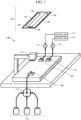
- FIG. 1 shows a configuration diagram of a nucleic acid analyzer 100 according to a first embodiment of the invention.
- the nucleic acid analyzer 100 includes a substrate 107, an introduction flow path 108, discharge flow paths 109 and 110, reagent aspiration mechanisms 111 and 112, control units 113 and 114, an imaging mechanism 115, reagent containers 116, and a reagent selection mechanism 117.
- the substrate 107 can be attached to and detached from a device main body. Other components are provided on a device main body side.
- the substrate 107 includes at least two flow paths 101 and 102, at least one inlet portion 103, at least two outlet portions 104 and 105, and at least one flow path branch point 106.
- the flow paths 101 and 102 are used to fix colonies containing DNA fragments and analyze base sequences of DNA.
- Each reagent is introduced into the substrate 107 from the inlet portion 103.
- the reagent is discharged from the outlet portions 104 and 105.
- the flow path branch point 106 is a location at which a flow path is branched into flow paths (a merging point of the flow paths).
- the flow path 101 connects between the inlet portion 103 and the outlet portion 104, and the flow path 102 connects between the inlet portion 103 and the outlet portion 105.
- the introduction flow path 108 is connected to the inlet portion 103.
- the reagent is introduced into the substrate 107 via the introduction flow path 108 and the inlet portion 103.
- the discharge flow path 109 is connected to the outlet portion 104, and the discharge flow path 110 is connected to the outlet portion 105.
- the reagent aspiration mechanism 111 aspirates the reagent flowing through the discharge flow path 109, and the reagent aspiration mechanism 112 aspirates the reagent flowing through the discharge flow path 110.
- the control unit 113 controls the reagent aspiration mechanism 111, and the control unit 114 controls the reagent aspiration mechanism 112.
- the imaging mechanism 115 captures a fluorescent image of the colonies containing the DNA fragments.
- Reagents are contained in the reagent containers 116.
- the reagent selection mechanism 117 selects a reagent to be introduced into the substrate 107 by selectively connecting to any one of the reagent containers 116.
- one inlet portion 103 of the substrate 107 and one introduction flow path 108 are provided, and two or more inlet portions 103 and two or more introduction flow paths 108 may be provided as long as the number of the inlet portions 103 and the number of the introduction flow paths 108 are both smaller than the number of the outlet portions 104 and 105.
- two outlet portions 104 and 105 and two discharge flow paths 109 and 110 are provided, and the number of the outlet portions 104 and 105 and the discharge flow paths 109 and 110 may be three or more.
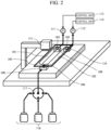
- FIG. 2 shows a configuration diagram when the substrate 107 is mounted on the nucleic acid analyzer 100.
- the reagent selection mechanism 117 selects a reagent required for each reaction step.
- the reagent aspiration mechanisms 111 and 112 aspirate the reagent.
- the amount of reagent flowing into the flow path 101 is controlled by the control unit 113, and the amount of reagent flowing into the flow path 102 is controlled by the control unit 114.
- the number of the introduction flow paths 108 can be minimized by providing the flow path branch point 106 on the substrate. Therefore, even when a branched flow path structure is provided, it is not necessary to replace a branched flow path on a device side with a reagent as in the related art, and thus it is possible to prevent excessive reagents from being consumed.
- FIG. 3 shows a configuration diagram when a substrate 301 having a size different from that of the substrate 107 is mounted on the nucleic acid analyzer 100.
- the substrate 301 includes one flow path 302, one inlet portion 303, and one outlet portion 304.
- the inlet portion 303 is connected to the introduction flow path 108
- the outlet portion 304 is connected to the discharge flow path 109.
- the flow path 302 connects the inlet portion 303 and the outlet portion 304.
- the reagent aspiration mechanism 111 introduces the reagent into the flow path 302 of the substrate 301 via the reagent selection mechanism 117, the inlet portion 303, and the outlet portion 304.
- the substrate 107 includes the flow path branch point 106, and a reagent is branched from the flow path branch point 106 to each flow path on the substrate 107.
- the flow path branch point 106 is disposed on a substrate 107 side. Accordingly, it is sufficient to provide the minimum number of introduction flow paths 108 on the device side (if one inlet portion 103 is provided, one introduction flow path 108 is also provided). Therefore, it is not necessary to replace the branched flow path on the device side with the reagent as in the related art, and thus it is possible to prevent a reagent consumption amount.
- the nucleic acid analyzer 100 even when the substrate 107 is replaced with the substrate 301, no branched flow path that is not connected to the substrate 301 is generated, and thus unnecessary dead volume does not occur between the reagent containers 116 and the inlet portion 303. Therefore, it is possible to prevent contamination of the reagent or the bubbles remaining in the branched flow path portion that is not connected (not used) to the substrate 301 as in the related art.
- FIG. 4 shows a configuration diagram of the nucleic acid analyzer 100 according to a second embodiment of the invention.
- the discharge flow path 109 is connected to a reagent aspiration mechanism 403 via a first solenoid valve 401
- the discharge flow path 110 is connected to a reagent aspiration mechanism 403 via a second solenoid valve 402.
- Other configurations are the same as those according to the first embodiment.
- control unit 404 (a) opens the first solenoid valve 401 when a desired amount of reagent is to be introduced into the flow path 101, and controls the reagent aspiration mechanism 403 via the control unit 404 of the reagent aspiration mechanism in a state where the second solenoid valve 402 is closed, and (b) opens the second solenoid valve 402 when a desired amount of reagent is to be introduced into the flow path 102, and controls the reagent aspiration mechanism 403 in a state where the first solenoid valve 401 is closed.
- the first solenoid valve 401 is opened to introduce the reagent, and then the second solenoid valve 402 is opened to introduce the reagent; when the substrate 301 is used, only the first solenoid valve 401 is opened to introduce the reagent.
- the nucleic acid analyzer 100 according to the second embodiment can reduce the number of reagent aspiration mechanisms and the number of control units as compared with the first embodiment. Accordingly, it is possible to simplify a structure particularly after the discharge flow paths.
- FIG. 4 two solenoid valves are provided in order to select a flow path for discharging the reagent, but the flow path can also be selected using one three-way solenoid valve. In addition, the discharge flow path may be selected by other appropriate mechanisms.
- FIG. 5 shows a configuration diagram of the nucleic acid analyzer 100 according to a third embodiment of the invention.
- a block 501 provided on a reagent introduction side are a block 501, a first reagent selection solenoid valve 502, a second reagent selection solenoid valve 503, a third reagent selection solenoid valve 504, a first reagent container 505, a second reagent container 506, and a third reagent container 507.
- Other configurations are the same as those according to the first embodiment.
- the block 501 includes a plurality of branched flow paths connected to the inlet portion 103.
- the reagent is aspirated by the reagent aspiration mechanisms 111 and 112 in a state where the first reagent selection solenoid valve 502 is opened and the second reagent selection solenoid valve 503 and the third reagent selection solenoid valve 504 are closed.
- the second reagent container 506 and the third reagent container 507 are connected to the substrate 107, a desired reagent is selectively introduced into the substrate 107 by opening the corresponding second reagent selection solenoid valve 503 or the corresponding third reagent selection solenoid valve 504. The same applies to a case of using the substrate 301.
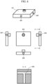
- FIG. 6 is a configuration diagram of the block 501.
- An upper part of FIG. 6 is a perspective view
- a middle part of FIG. 6 includes a top view, left and right side views, and a front view
- a lower part of FIG. 6 is a cross-sectional view taken along line AA.
- the block 501 includes an outflow port 602 through which reagents flow out to a substrate and in contact with a flow path of the substrate, a first reagent inflow port 603, a second reagent inflow port 604, and a third reagent inflow port 605.
- the branched flow paths from reagent inflow ports merge at a merging point 606 and reach the outflow port 602 through which the reagents flow out to the substrate.
- the number of reagent inflow ports may be increased or decreased according to the number of reagents required for reaction, and the number of merging points 606 may also be increased or decreased accordingly.
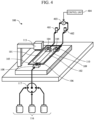
- FIG. 7 is a configuration diagram of the nucleic acid analyzer 100 according to a fourth embodiment of the invention.
- the nucleic acid analyzer 100 includes grooves 701 and 702 on a stage 705 on which a substrate is placed.
- the groove 701 is connected to a pump 703, and the pump 703 evacuates the groove 701.
- the groove 702 is connected to a pump 704, and the pump 704 evacuates the groove 702.
- the pumps 703 and 704 can be controlled by, for example, the control units 113 and 114, respectively.
- Other configurations are the same as those according to the first to third embodiments, and thus descriptions thereof are omitted in FIG. 7 .
- FIG. 8 Other configurations are the same as those according to the first to third embodiments, and thus descriptions thereof are omitted in FIG. 7 .
- FIG. 8 The same applies to FIG. 8 .
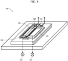
- FIG. 8 is a diagram showing a state in which the substrate 301 is used.
- the substrate 301 When placed on the stage 705, the substrate 301 has a size and a shape to cover the groove 701 while not overlapping the groove 702.
- the substrate 301 When the substrate 301 is used, the substrate 301 is placed on the groove 701, and the pump 703 aspirates the substrate 301 via the groove 701. Accordingly, the substrate 301 can be fixed on the stage.
- the substrate 107 When placed on the stage 705, the substrate 107 has a size and a shape to cover both the grooves 701 and 702. Similarly, when the substrate 107 is used, the substrate 107 is placed on the grooves 701 and 702, and the pumps 703 and 704 aspirate the substrate 107 via the grooves 701 and 702, respectively. Accordingly, the substrate 107 can be fixed on the stage.
- a mechanism that fixes the substrate is divided into a plurality of (two grooves 701 and 702 in FIG. 7 ) mechanisms, and which fixing mechanism is used is switched according to the size of the substrate. Accordingly, it is possible to flexibly use substrates of various sizes and to reliably fix any substrate.
- the grooves 701 and 702 are disposed on the stage 705, but positions of the grooves are not limited thereto, and may be any positions as long as the substrate covers these grooves when the substrate 107 or the substrate 301 is mounted on the nucleic acid analyzer 100.
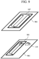
- FIG. 9 is a configuration diagram of the substrates 107 and 301 used in the nucleic acid analyzer 100 according to a fifth embodiment of the invention.
- Each substrate can be accommodated in a casing 901.
- the casing 901 may be shared between the substrates 107 and 301, and may be provided with separate substrates having different sizes and made of different materials.
- the casing 901 has a planar size slightly larger than the substrate 301. Accordingly, when the substrate 301 is accommodated in the casing 901 and placed on the stage 705, the discharge flow path 110 on a not-used side can be closed. If the discharge flow path 110 is opened for a long time (for example, from about several hours to about several days) without being used, dust or the like may clog the inside of the discharge flow path 110. By attaching the casing 901, such clogging can be prevented even when the substrate 107 is replaced with the substrate 301.
- the invention is not limited to the embodiments described above, and includes various modifications.
- the above-described embodiments are described in detail for easy understanding of the invention, and the invention is not necessarily limited to those including all the configurations described above.
- a part of a configuration according to one embodiment can be replaced with a configuration according to another embodiment, and the configuration according to another embodiment can be added to the configuration according to one embodiment.
- a part of a configuration according to each embodiment can be added, deleted, or replaced with another configuration.
- an imaging range of the imaging mechanism 115 when the substrate 107 is used is larger than that when the substrate 301 is used. Therefore, when the substrate is moved within the imaging range of the imaging mechanism 115, a moving range is larger when the substrate 107 is used. For example, when the substrate is placed on the stage 705 and moved with the stage 705, a moving range of the stage 705 is larger when the substrate 107 is used. Alternatively, if the imaging mechanism 115 can scan an imaging range or an imaging location, the imaging range is larger when the substrate 107 is used.
- control units 113, 114, and 404 can be implemented by hardware such as a circuit device in which functions of the control units are implemented, and can be implemented by an arithmetic device executing software in which the functions of the control units are implemented.
Landscapes
- Health & Medical Sciences (AREA)
- Chemical & Material Sciences (AREA)
- Life Sciences & Earth Sciences (AREA)
- General Health & Medical Sciences (AREA)
- Physics & Mathematics (AREA)
- Analytical Chemistry (AREA)
- Biochemistry (AREA)
- Immunology (AREA)
- Pathology (AREA)
- General Physics & Mathematics (AREA)
- Chemical Kinetics & Catalysis (AREA)
- Clinical Laboratory Science (AREA)
- Molecular Biology (AREA)
- Engineering & Computer Science (AREA)
- Nuclear Medicine, Radiotherapy & Molecular Imaging (AREA)
- Hematology (AREA)
- Dispersion Chemistry (AREA)
- Organic Chemistry (AREA)
- Genetics & Genomics (AREA)
- Zoology (AREA)
- Wood Science & Technology (AREA)
- Bioinformatics & Cheminformatics (AREA)
- Biomedical Technology (AREA)
- Optics & Photonics (AREA)
- Fluid Mechanics (AREA)
- Sustainable Development (AREA)
- Biotechnology (AREA)
- Microbiology (AREA)
- General Engineering & Computer Science (AREA)
- Apparatus Associated With Microorganisms And Enzymes (AREA)
- Optical Measuring Cells (AREA)
- Measuring Or Testing Involving Enzymes Or Micro-Organisms (AREA)
- Investigating, Analyzing Materials By Fluorescence Or Luminescence (AREA)
- Investigating Or Analysing Materials By The Use Of Chemical Reactions (AREA)
Abstract
Description
- The present invention relates to a nucleic acid analyzer.
- A nucleic acid analyzer is known as a device for analyzing base sequences of a deoxyribonucleic acid (DNA). The nucleic acid analyzer is a device for analyzing the base sequences of DNA by denaturing DNA fragments into a single strand, using the single strand as a model, extending a nucleic acid attached with a fluorescent label by one base each time, and sequentially capturing a fluorescent image. When analysis is performed, a substrate in which a flow path is provided in a plate made of a partially or entirely transparent material is prepared, and colonies containing a plurality of cloned DNA fragments denatured into a single strand are fixed in a reaction field provided in the flow path of the substrate. In order to enable identification of four types of nucleotides (adenine, cytosine, guanine, thymine) forming DNA for the colonies containing the plurality of DNA fragments, a reagent that fluorescently labels each base of DNA, a reagent that cleans the flow path, and the like are alternately sent. The base sequences of DNA can be sequentially analyzed by capturing, as a fluorescent image, a process in which the colonies are restored to contain the double-stranded DNA fragments.
- In analysis of base sequences of DNA in the nucleic acid analyzer, first, for the colonies containing the plurality of DNA fragments fixed in the reaction field provided in the flow path of the substrate, a reagent required for each reaction process is selected from a plurality of types of reagents and is sent to the flow path of the substrate, and thus each base of the colonies containing the DNA fragments in the flow path is fluorescently modified. Further, the colonies containing the fluorescently modified DNA fragments are observed. The base sequences are analyzed as described above.
- In such a nucleic acid analyzer, it is considered to increase an area of the reaction field by providing a plurality of flow paths on the substrate in order to improve throughput. A nucleic acid analyzer using a substrate having a plurality of flow paths is reported in PTL 1.
- PTL 1:
US8241573B2 - PTL 1 describes a configuration of a nucleic acid analyzer that sends a reagent to a substrate having a plurality of flow paths. However, the nucleic acid analyzer in PTL 1 requires a branched flow path structure for connecting reagents with a plurality of substrate flow paths in order to introduce the reagents into the plurality of flow paths, and the substrate flow paths and the branched flow path are both required to be replaced with the reagents, and thus a reagent consumption amount increases.
- In addition, when it is considered to use substrates of different sizes in order to cope with a plurality of types of throughput (for example, a substrate having a half number of flow paths is used in order to implement nucleic acid analysis at half throughput), a branched flow path that is not connected to the substrate is generated in the branched flow path structure. A branched flow path portion that is not connected to the substrate becomes a dead volume, and a remaining drug solution or bubbles cannot be replaced with the reagents, thereby causing contamination. Therefore, it is not desirable to use substrates of different sizes.
- In view of the above problems, an object of the invention is to provide a nucleic acid analyzer capable of mounting a plurality of types of substrates having different numbers of flow paths while preventing an increase in reagent consumption amount due to a branched flow path structure.
- In the nucleic acid analyzer according to the invention, a first substrate includes an inlet portion connected to an introduction path, a first outlet portion connected to a first discharge path, a second outlet portion connected to a second discharge path, a first flow path configured to guide a reagent from the inlet portion to the first outlet portion, a second flow path configured to guide the reagent from the inlet portion to the second outlet portion, and a branch portion configured to branch the reagent from the inlet portion to the first flow path and the second flow path, in which the first flow path and the second flow path are connected to each other only at the branch portion.
- According to the nucleic acid analyzer of the invention, by providing a branch point of the flow paths in the substrate, it is possible to minimize the number of introduction flow paths and eliminate an increase in reagent consumption amount due to an increase in the number of flow paths of the substrate. Further, by stabilizing the number of inlet portions of the substrate regardless of the number of flow paths on the substrate, it is possible to mount a plurality of types of substrates having different numbers of flow paths without generating a dead volume in the same device configuration.
-
- [
FIG. 1] FIG. 1 shows a configuration diagram of anucleic acid analyzer 100 according to a first embodiment. - [
FIG. 2] FIG. 2 shows a configuration diagram when asubstrate 107 is mounted on thenucleic acid analyzer 100. - [
FIG. 3] FIG. 3 shows a configuration diagram when asubstrate 301 having a size different from that of thesubstrate 107 is mounted on thenucleic acid analyzer 100. - [
FIG. 4] FIG. 4 shows a configuration diagram of thenucleic acid analyzer 100 according to a second embodiment. - [
FIG. 5] FIG. 5 shows a configuration diagram of thenucleic acid analyzer 100 according to a third embodiment. - [
FIG. 6] FIG. 6 shows a configuration diagram of ablock 501. - [
FIG. 7] FIG. 7 is a configuration diagram of thenucleic acid analyzer 100 according to a fourth embodiment. - [
FIG. 8] FIG. 8 is a diagram showing a state in which thesubstrate 301 is used. - [
FIG. 9] FIG. 9 is a configuration diagram of thesubstrates nucleic acid analyzer 100 according to a fifth embodiment. -
FIG. 1 shows a configuration diagram of anucleic acid analyzer 100 according to a first embodiment of the invention. Thenucleic acid analyzer 100 includes asubstrate 107, anintroduction flow path 108,discharge flow paths reagent aspiration mechanisms control units imaging mechanism 115,reagent containers 116, and areagent selection mechanism 117. Thesubstrate 107 can be attached to and detached from a device main body. Other components are provided on a device main body side. - The
substrate 107 includes at least twoflow paths inlet portion 103, at least twooutlet portions path branch point 106. Theflow paths substrate 107 from theinlet portion 103. The reagent is discharged from theoutlet portions path branch point 106 is a location at which a flow path is branched into flow paths (a merging point of the flow paths). Theflow path 101 connects between theinlet portion 103 and theoutlet portion 104, and theflow path 102 connects between theinlet portion 103 and theoutlet portion 105. - The
introduction flow path 108 is connected to theinlet portion 103. The reagent is introduced into thesubstrate 107 via theintroduction flow path 108 and theinlet portion 103. Thedischarge flow path 109 is connected to theoutlet portion 104, and thedischarge flow path 110 is connected to theoutlet portion 105. Thereagent aspiration mechanism 111 aspirates the reagent flowing through thedischarge flow path 109, and thereagent aspiration mechanism 112 aspirates the reagent flowing through thedischarge flow path 110. Thecontrol unit 113 controls thereagent aspiration mechanism 111, and thecontrol unit 114 controls thereagent aspiration mechanism 112. Theimaging mechanism 115 captures a fluorescent image of the colonies containing the DNA fragments. Reagents are contained in thereagent containers 116. Thereagent selection mechanism 117 selects a reagent to be introduced into thesubstrate 107 by selectively connecting to any one of thereagent containers 116. - In
FIG. 1 , oneinlet portion 103 of thesubstrate 107 and oneintroduction flow path 108 are provided, and two ormore inlet portions 103 and two or moreintroduction flow paths 108 may be provided as long as the number of theinlet portions 103 and the number of theintroduction flow paths 108 are both smaller than the number of theoutlet portions FIG. 1 , twooutlet portions discharge flow paths outlet portions discharge flow paths -
FIG. 2 shows a configuration diagram when thesubstrate 107 is mounted on thenucleic acid analyzer 100. Thereagent selection mechanism 117 selects a reagent required for each reaction step. Next, thereagent aspiration mechanisms flow path 101 is controlled by thecontrol unit 113, and the amount of reagent flowing into theflow path 102 is controlled by thecontrol unit 114. By independently controlling a reagent aspirating amount by each reagent aspiration mechanism in such a manner, it is possible to introduce a desired reagent amount into each flow path. - As described above, in the substrate having a plurality of flow paths, the number of the
introduction flow paths 108 can be minimized by providing the flowpath branch point 106 on the substrate. Therefore, even when a branched flow path structure is provided, it is not necessary to replace a branched flow path on a device side with a reagent as in the related art, and thus it is possible to prevent excessive reagents from being consumed. -
FIG. 3 shows a configuration diagram when asubstrate 301 having a size different from that of thesubstrate 107 is mounted on thenucleic acid analyzer 100. Thesubstrate 301 includes oneflow path 302, oneinlet portion 303, and oneoutlet portion 304. Theinlet portion 303 is connected to theintroduction flow path 108, and theoutlet portion 304 is connected to thedischarge flow path 109. Theflow path 302 connects theinlet portion 303 and theoutlet portion 304. Thereagent aspiration mechanism 111 introduces the reagent into theflow path 302 of thesubstrate 301 via thereagent selection mechanism 117, theinlet portion 303, and theoutlet portion 304. - As shown in
FIG. 3 , even whensubstrates 301 of different sizes are mounted, an unnecessary dead volume does not occur between thereagent containers 116 and theinlet portion 303. Therefore, contamination of the reagent and bubbles remaining in a branched flow path portion that is not connected (not used) to thesubstrate 301 as in the related art does not occur. - In the
nucleic acid analyzer 100 according to the first embodiment, thesubstrate 107 includes the flowpath branch point 106, and a reagent is branched from the flowpath branch point 106 to each flow path on thesubstrate 107. In other words, the flowpath branch point 106 is disposed on asubstrate 107 side. Accordingly, it is sufficient to provide the minimum number ofintroduction flow paths 108 on the device side (if oneinlet portion 103 is provided, oneintroduction flow path 108 is also provided). Therefore, it is not necessary to replace the branched flow path on the device side with the reagent as in the related art, and thus it is possible to prevent a reagent consumption amount. - In the
nucleic acid analyzer 100 according to the first embodiment, even when thesubstrate 107 is replaced with thesubstrate 301, no branched flow path that is not connected to thesubstrate 301 is generated, and thus unnecessary dead volume does not occur between thereagent containers 116 and theinlet portion 303. Therefore, it is possible to prevent contamination of the reagent or the bubbles remaining in the branched flow path portion that is not connected (not used) to thesubstrate 301 as in the related art. -
FIG. 4 shows a configuration diagram of thenucleic acid analyzer 100 according to a second embodiment of the invention. InFIG. 4 , descriptions of parts having the same functions as those of the configuration shown inFIG. 1 will be omitted. In the second embodiment, thedischarge flow path 109 is connected to areagent aspiration mechanism 403 via afirst solenoid valve 401, and thedischarge flow path 110 is connected to areagent aspiration mechanism 403 via asecond solenoid valve 402. Other configurations are the same as those according to the first embodiment. - In the second embodiment, the control unit 404 (a) opens the
first solenoid valve 401 when a desired amount of reagent is to be introduced into theflow path 101, and controls thereagent aspiration mechanism 403 via thecontrol unit 404 of the reagent aspiration mechanism in a state where thesecond solenoid valve 402 is closed, and (b) opens thesecond solenoid valve 402 when a desired amount of reagent is to be introduced into theflow path 102, and controls thereagent aspiration mechanism 403 in a state where thefirst solenoid valve 401 is closed. - Specifically, when the
substrate 107 is used, thefirst solenoid valve 401 is opened to introduce the reagent, and then thesecond solenoid valve 402 is opened to introduce the reagent; when thesubstrate 301 is used, only thefirst solenoid valve 401 is opened to introduce the reagent. - The
nucleic acid analyzer 100 according to the second embodiment can reduce the number of reagent aspiration mechanisms and the number of control units as compared with the first embodiment. Accordingly, it is possible to simplify a structure particularly after the discharge flow paths. - In
FIG. 4 , two solenoid valves are provided in order to select a flow path for discharging the reagent, but the flow path can also be selected using one three-way solenoid valve. In addition, the discharge flow path may be selected by other appropriate mechanisms. -
FIG. 5 shows a configuration diagram of thenucleic acid analyzer 100 according to a third embodiment of the invention. InFIG. 5 , descriptions of parts having the same functions as those of the configuration shown inFIG. 1 will be omitted. In the third embodiment, provided on a reagent introduction side are ablock 501, a first reagentselection solenoid valve 502, a second reagentselection solenoid valve 503, a third reagentselection solenoid valve 504, afirst reagent container 505, asecond reagent container 506, and athird reagent container 507. Other configurations are the same as those according to the first embodiment. - The
block 501 includes a plurality of branched flow paths connected to theinlet portion 103. When thefirst reagent container 505 is connected to thesubstrate 107, the reagent is aspirated by thereagent aspiration mechanisms selection solenoid valve 502 is opened and the second reagentselection solenoid valve 503 and the third reagentselection solenoid valve 504 are closed. Similarly, when thesecond reagent container 506 and thethird reagent container 507 are connected to thesubstrate 107, a desired reagent is selectively introduced into thesubstrate 107 by opening the corresponding second reagentselection solenoid valve 503 or the corresponding third reagentselection solenoid valve 504. The same applies to a case of using thesubstrate 301. -
FIG. 6 is a configuration diagram of theblock 501. An upper part ofFIG. 6 is a perspective view, a middle part ofFIG. 6 includes a top view, left and right side views, and a front view, and a lower part ofFIG. 6 is a cross-sectional view taken along line AA. Theblock 501 includes anoutflow port 602 through which reagents flow out to a substrate and in contact with a flow path of the substrate, a firstreagent inflow port 603, a secondreagent inflow port 604, and a thirdreagent inflow port 605. - In the
block 501, the branched flow paths from reagent inflow ports merge at amerging point 606 and reach theoutflow port 602 through which the reagents flow out to the substrate. Although three reagent inflow ports are provided inFIG. 6 , the number of reagent inflow ports may be increased or decreased according to the number of reagents required for reaction, and the number of mergingpoints 606 may also be increased or decreased accordingly. -
FIG. 7 is a configuration diagram of thenucleic acid analyzer 100 according to a fourth embodiment of the invention. In the fourth embodiment, thenucleic acid analyzer 100 includesgrooves stage 705 on which a substrate is placed. Thegroove 701 is connected to apump 703, and thepump 703 evacuates thegroove 701. Thegroove 702 is connected to apump 704, and thepump 704 evacuates thegroove 702. Thepumps control units FIG. 7 . The same applies toFIG. 8 . -
FIG. 8 is a diagram showing a state in which thesubstrate 301 is used. When placed on thestage 705, thesubstrate 301 has a size and a shape to cover thegroove 701 while not overlapping thegroove 702. When thesubstrate 301 is used, thesubstrate 301 is placed on thegroove 701, and thepump 703 aspirates thesubstrate 301 via thegroove 701. Accordingly, thesubstrate 301 can be fixed on the stage. - When placed on the
stage 705, thesubstrate 107 has a size and a shape to cover both thegrooves substrate 107 is used, thesubstrate 107 is placed on thegrooves pumps substrate 107 via thegrooves substrate 107 can be fixed on the stage. - As in the fourth embodiment, a mechanism that fixes the substrate is divided into a plurality of (two
grooves FIG. 7 ) mechanisms, and which fixing mechanism is used is switched according to the size of the substrate. Accordingly, it is possible to flexibly use substrates of various sizes and to reliably fix any substrate. - Although two
pumps FIG. 7 , one pump and a solenoid valve may be used to switch which groove is to be aspirated. Therefore, the number of pumps is set for the sake of convenience as long as which groove is to be aspirated can be switched according to the size of the substrate. - In
FIG. 7 , thegrooves stage 705, but positions of the grooves are not limited thereto, and may be any positions as long as the substrate covers these grooves when thesubstrate 107 or thesubstrate 301 is mounted on thenucleic acid analyzer 100. -
FIG. 9 is a configuration diagram of thesubstrates nucleic acid analyzer 100 according to a fifth embodiment of the invention. Each substrate can be accommodated in acasing 901. Thecasing 901 may be shared between thesubstrates - The
casing 901 has a planar size slightly larger than thesubstrate 301. Accordingly, when thesubstrate 301 is accommodated in thecasing 901 and placed on thestage 705, thedischarge flow path 110 on a not-used side can be closed. If thedischarge flow path 110 is opened for a long time (for example, from about several hours to about several days) without being used, dust or the like may clog the inside of thedischarge flow path 110. By attaching thecasing 901, such clogging can be prevented even when thesubstrate 107 is replaced with thesubstrate 301. - The invention is not limited to the embodiments described above, and includes various modifications. For example, the above-described embodiments are described in detail for easy understanding of the invention, and the invention is not necessarily limited to those including all the configurations described above. Further, a part of a configuration according to one embodiment can be replaced with a configuration according to another embodiment, and the configuration according to another embodiment can be added to the configuration according to one embodiment. A part of a configuration according to each embodiment can be added, deleted, or replaced with another configuration.
- In the above embodiments, an imaging range of the
imaging mechanism 115 when thesubstrate 107 is used is larger than that when thesubstrate 301 is used. Therefore, when the substrate is moved within the imaging range of theimaging mechanism 115, a moving range is larger when thesubstrate 107 is used. For example, when the substrate is placed on thestage 705 and moved with thestage 705, a moving range of thestage 705 is larger when thesubstrate 107 is used. Alternatively, if theimaging mechanism 115 can scan an imaging range or an imaging location, the imaging range is larger when thesubstrate 107 is used. - In the embodiments described above, the
control units -
- 100 nucleic acid analyzer
- 101 flow path
- 102 flow path
- 103 inlet portion
- 104 outlet portion
- 105 outlet portion
- 106 flow path branch point
- 107 substrate
- 108 introduction flow path
- 109 discharge flow path
- 110 discharge flow path
- 111 reagent aspiration mechanism
- 112 reagent aspiration mechanism
- 113 control unit
- 114 control unit
- 115 imaging mechanism
- 116 reagent container
- 117 reagent selection mechanism
- 301 substrate
- 302 flow path
- 303 inlet portion
- 304 outlet portion
- 401 first solenoid valve
- 402 second solenoid valve
- 403 reagent aspiration mechanism
- 404 control unit
- 501 block
- 502 first reagent selection solenoid valve
- 503 second reagent selection solenoid valve
- 504 third reagent selection solenoid valve
- 505 first reagent container
- 506 second reagent container
- 507 third reagent container
- 602 outflow port
- 603 first reagent inflow port
- 604 second reagent inflow port
- 605 third reagent inflow port
- 606 merging point
- 701 groove
- 702 groove
- 703 pump
- 704 pump
- 705 stage
- 901 casing
Claims (12)
- A nucleic acid analyzer comprising:a first substrate including a reaction field for analyzing a nucleic acid;an introduction path through which a reagent to be introduced into the first substrate is conveyed;a first discharge path through which the reagent discharged from the first substrate is conveyed;a second discharge path through which the reagent discharged from the first substrate is conveyed;a reagent selection mechanism configured to select the reagent to be introduced into the first substrate; andan aspiration mechanism configured to aspirate the reagent from upstream sides of the first discharge path and the second discharge path to introduce the reagent into the first substrate via the introduction path, whereinthe first substrate includes:an inlet portion connected to the introduction path;a first outlet portion connected to the first discharge path;a second outlet portion connected to the second discharge path;a first flow path configured to guide the reagent from the inlet portion to the first outlet portion;a second flow path configured to guide the reagent from the inlet portion to the second outlet portion; anda branch portion configured to branch the reagent from the inlet portion to the first flow path and the second flow path, andthe first flow path and the second flow path are connected to each other only at the branch portion.
- The nucleic acid analyzer according to claim 1, whereinthe nucleic acid analyzer is capable of exchanging the first substrate and the second substrate,the second substrate includes:a third outlet portion connected to the first discharge path; anda third flow path configured to guide the reagent from the inlet portion to the third outlet portion,when the first substrate is used, the aspiration mechanism aspirates the reagent via the first flow path, the first outlet portion, and the first discharge path, and aspirates the reagent via the second flow path, the second outlet portion, and the second discharge path, andwhen the second substrate is used, the aspiration mechanism aspirates the reagent via the third flow path and the third outlet portion and via one of the first discharge path and the second discharge path.
- The nucleic acid analyzer according to claim 1, further comprising:a connection flow path configured to connect a reagent container containing the reagent to the introduction path, whereinthe connection flow path does not branch in a path from the reagent container to the introduction path.
- The nucleic acid analyzer according to claim 1, further comprising:a first groove located below the first substrate when the first substrate is attached to the nucleic acid analyzer; anda first pump configured to aspirate the first substrate via the first groove, whereinthe first pump fixes the first substrate to the nucleic acid analyzer by aspirating the first substrate via the first groove.
- The nucleic acid analyzer according to claim 2, further comprising:a first groove located below the first substrate when the first substrate is attached to the nucleic acid analyzer;a second groove located below the first substrate when the first substrate is attached to the nucleic acid analyzer;a first pump configured to aspirate the first substrate via the first groove; anda second pump configured to aspirate the first substrate via the second groove, whereinthe first substrate has a shape and a planar size such that both the first groove and the second groove are covered with the first substrate when the first substrate is attached to the nucleic acid analyzer,the second substrate has a shape and a planar size such that the first groove is covered with the second substrate and the second groove is not covered with the second substrate when the second substrate is attached to the nucleic acid analyzer,the first pump and the second pump fix the first substrate to the nucleic acid analyzer by aspirating the first substrate via the first groove and the second groove, respectively, andthe first pump fixes the second substrate to the nucleic acid analyzer by aspirating the second substrate via the first groove.
- The nucleic acid analyzer according to claim 2, whereinthe second substrate is accommodated in a casing, andthe casing has a shape and a size to close the second discharge path when the second substrate is attached to the nucleic acid analyzer.
- The nucleic acid analyzer according to claim 2, further comprising:an imaging mechanism configured to image a specimen flowing through the first substrate or the second substrate, whereina range in which the imaging mechanism captures an image when the first substrate is attached to the nucleic acid analyzer is larger than a range in which the imaging mechanism captures an image when the second substrate is attached to the nucleic acid analyzer.
- The nucleic acid analyzer according to claim 2, whereinthe aspiration mechanism includes:a first aspiration unit connected to the first discharge path; anda second aspiration unit connected to the second discharge path,the first aspiration unit aspirates the reagent via the first discharge path, and the second aspiration unit aspirates the reagent via the second discharge path to introduce the reagent into the first substrate, andthe first aspiration unit aspirates the reagent via the first discharge path to introduce the reagent into the second substrate.
- The nucleic acid analyzer according to claim 2, whereinthe aspiration mechanism includes:an aspiration unit connected to the first discharge path and the second discharge path;a first valve configured to block or open the first discharge path; anda second valve configured to block or open the second discharge path,the first valve opens the first discharge path, the second valve blocks the second discharge path, and the aspiration unit aspirates the reagent to introduce the reagent into the first flow path,the first valve blocks the first discharge path, the second valve opens the second discharge path, and the aspiration unit aspirates the reagent to introduce the reagent into the second flow path, andone of the first valve and the second valve is opened while the other valve is blocked, and the aspiration unit aspirates the reagent to introduce the reagent into the third flow path.
- The nucleic acid analyzer according to claim 1, wherein
the reagent selection mechanism includes:a first branch path connected to a first reagent container containing a first reagent;a second branch path connected to a second reagent container containing a second reagent;a merging point at which the first branch path and the second branch path merge; anda flow path configured to connect the merging point and the inlet portion. - The nucleic acid analyzer according to claim 10, whereinthe reagent selection mechanism includes:a third valve configured to block or open a flow path between the first branch path and the first reagent container; anda fourth valve configured to block or open a flow path between the second branch path and the second reagent container,the reagent selection mechanism selects the first reagent by opening the third valve and blocking the fourth valve, andthe reagent selection mechanism selects the second reagent by blocking the third valve and opening the fourth valve.
- The nucleic acid analyzer according to claim 1, wherein
the number of paths configured to convey the reagent discharged from the first substrate is larger than the number of introduction paths.
Applications Claiming Priority (1)
| Application Number | Priority Date | Filing Date | Title |
|---|---|---|---|
| PCT/JP2020/022025 WO2021245859A1 (en) | 2020-06-03 | 2020-06-03 | Nucleic acid analyzer |
Publications (3)
| Publication Number | Publication Date |
|---|---|
| EP4163357A1 true EP4163357A1 (en) | 2023-04-12 |
| EP4163357A4 EP4163357A4 (en) | 2024-02-28 |
| EP4163357B1 EP4163357B1 (en) | 2025-08-06 |
Family
ID=78830205
Family Applications (1)
| Application Number | Title | Priority Date | Filing Date |
|---|---|---|---|
| EP20939354.5A Active EP4163357B1 (en) | 2020-06-03 | 2020-06-03 | Nucleic acid analyzer |
Country Status (5)
| Country | Link |
|---|---|
| US (1) | US20230219088A1 (en) |
| EP (1) | EP4163357B1 (en) |
| JP (1) | JP7549016B2 (en) |
| CN (1) | CN115769063B (en) |
| WO (1) | WO2021245859A1 (en) |
Families Citing this family (1)
| Publication number | Priority date | Publication date | Assignee | Title |
|---|---|---|---|---|
| US20250235870A1 (en) * | 2022-03-14 | 2025-07-24 | Encodia, Inc. | Reagent cartridge and temperature control system |
Family Cites Families (24)
| Publication number | Priority date | Publication date | Assignee | Title |
|---|---|---|---|---|
| JPH07274935A (en) * | 1994-04-13 | 1995-10-24 | Seiko Instr Inc | DNA chemical reactor |
| JP3938982B2 (en) * | 1997-08-29 | 2007-06-27 | オリンパス株式会社 | DNA capillary |
| JP4797196B2 (en) * | 2001-02-14 | 2011-10-19 | 株式会社 フューエンス | Microchip |
| JP4106977B2 (en) * | 2002-06-21 | 2008-06-25 | 株式会社日立製作所 | Analysis chip and analyzer |
| US20050266582A1 (en) * | 2002-12-16 | 2005-12-01 | Modlin Douglas N | Microfluidic system with integrated permeable membrane |
| JP2005090995A (en) * | 2003-09-12 | 2005-04-07 | Olympus Corp | Method and system for injecting sample |
| JPWO2007058077A1 (en) * | 2005-11-18 | 2009-04-30 | コニカミノルタエムジー株式会社 | Genetic testing method, genetic testing microreactor, and genetic testing system |
| SG170802A1 (en) * | 2006-03-31 | 2011-05-30 | Solexa Inc | Systems and devices for sequence by synthesis analysis |
| JP5494480B2 (en) * | 2007-06-11 | 2014-05-14 | 和光純薬工業株式会社 | Microchip large capacity PCR using integrated real-time CE detection |
| WO2009010970A2 (en) * | 2007-07-16 | 2009-01-22 | Mabat Chemical Systems Ltd. | Modular chemical delivery unit |
| JP2009192291A (en) * | 2008-02-13 | 2009-08-27 | Seiko Epson Corp | Biological substance detection chip and biological substance detection method |
| US8173080B2 (en) * | 2008-02-14 | 2012-05-08 | Illumina, Inc. | Flow cells and manifolds having an electroosmotic pump |
| US10240186B2 (en) * | 2011-07-14 | 2019-03-26 | Fluxion Biosciences, Inc. | Devices, systems, and methods for magnetic separation |
| KR20130135111A (en) * | 2012-05-30 | 2013-12-10 | 나노바이오시스 주식회사 | Multi-channel device for distributing liquid sample, device for extracting nucleic acid comprising the same, and method for extracting nucleic acid using the same |
| JP6295578B2 (en) * | 2013-09-30 | 2018-03-20 | 凸版印刷株式会社 | Reaction vessel, nucleic acid analyzer, and nucleic acid analysis method |
| JP2016011943A (en) * | 2013-12-24 | 2016-01-21 | 株式会社リコー | Analysis device |
| US20150276692A1 (en) * | 2014-03-28 | 2015-10-01 | Uop Llc | Process for controlling an ionic liquid process and regeneration using a viscosity measurement |
| KR101764585B1 (en) * | 2014-10-30 | 2017-08-10 | 이화여자대학교 산학협력단 | Microfluidic device for detection of target gene, method of preparing the same and detection method using the same |
| EP3397946B1 (en) * | 2015-12-30 | 2021-12-01 | Bio-Rad Laboratories, Inc. | Optical detection system for particles |
| CN108265003A (en) * | 2016-12-30 | 2018-07-10 | 广州康昕瑞基因健康科技有限公司 | Multichannel gene sequencing reaction cell and multichannel gene sequencing reaction device |
| JP6931540B2 (en) * | 2017-02-27 | 2021-09-08 | シスメックス株式会社 | Liquid feeding method using a sample processing chip, liquid feeding device for a sample processing chip |
| JP7128509B2 (en) * | 2018-04-20 | 2022-08-31 | 国立大学法人東海国立大学機構 | Channel chip for detecting plant substances. |
| JP7270948B2 (en) * | 2018-07-30 | 2023-05-11 | 国立大学法人北海道大学 | Substance detection device |
| JP2022043362A (en) * | 2018-11-12 | 2022-03-16 | 株式会社日立ハイテク | Nucleic acid analysis device |
-
2020
- 2020-06-03 US US17/928,997 patent/US20230219088A1/en active Pending
- 2020-06-03 JP JP2022529235A patent/JP7549016B2/en active Active
- 2020-06-03 EP EP20939354.5A patent/EP4163357B1/en active Active
- 2020-06-03 WO PCT/JP2020/022025 patent/WO2021245859A1/en not_active Ceased
- 2020-06-03 CN CN202080101462.6A patent/CN115769063B/en active Active
Also Published As
| Publication number | Publication date |
|---|---|
| JPWO2021245859A1 (en) | 2021-12-09 |
| CN115769063B (en) | 2026-01-09 |
| CN115769063A (en) | 2023-03-07 |
| WO2021245859A1 (en) | 2021-12-09 |
| EP4163357B1 (en) | 2025-08-06 |
| US20230219088A1 (en) | 2023-07-13 |
| EP4163357A4 (en) | 2024-02-28 |
| JP7549016B2 (en) | 2024-09-10 |
Similar Documents
| Publication | Publication Date | Title |
|---|---|---|
| EP3361263B1 (en) | Specimen treatment chip | |
| WO2019201231A1 (en) | System for extracting biomolecules from a sample and related methods | |
| US10906043B2 (en) | Microfluidic based integrated sample analysis system | |
| US8940249B2 (en) | System for the analysis of liquid samples | |
| EP2311563A1 (en) | Processing units and methods for the processing of liquid samples | |
| US20220074960A1 (en) | Sample pretreatment device, analysis system including the device, and autosampler | |
| US20120214167A1 (en) | Apparatus for bio-automation | |
| WO2014144789A2 (en) | Methods and devices for analysis of defined multicellular combinations | |
| JP7814509B2 (en) | Flow path system, gene sequencer, and reagent recovery method | |
| TWI764279B (en) | A method for loading a sample and an apparatus for analyzing a sample | |
| EP4163357B1 (en) | Nucleic acid analyzer | |
| CN116618106A (en) | Fluid transport system with variable flow direction, detection system and fluid transport method thereof | |
| US20240118239A1 (en) | Cartridge, Electrowetting Sample Processing System and Feeding Thereof | |
| US11313872B2 (en) | Dispensing device and sample analysis device | |
| KR100579831B1 (en) | Assemble Microfluidic Biosample Processing System | |
| EP4178721A1 (en) | Sampling device and systems | |
| EP3990178B1 (en) | Cartridge, electrowetting sample processing system and feeding thereof | |
| WO2019214859A1 (en) | Cartridge, electrowetting sample processing system and bead manupulation method | |
| JP7724381B2 (en) | Dispensing device and genetic testing device equipped with same | |
| CN117580646A (en) | Microfluidic devices and methods for cell analysis | |
| JP7458379B2 (en) | Flow path devices and inspection systems | |
| US20260124617A1 (en) | Fluid system, fluid transport method, gene sequencer, and biochemical assay method | |
| EP4624048A1 (en) | Method for controlling liquid inflow of liquid path system, liquid path system, apparatus, device, and storage medium | |
| WO2024069182A1 (en) | Microfluidic loader | |
| US20210023551A1 (en) | Fluid handling device |
Legal Events
| Date | Code | Title | Description |
|---|---|---|---|
| STAA | Information on the status of an ep patent application or granted ep patent |
Free format text: STATUS: THE INTERNATIONAL PUBLICATION HAS BEEN MADE |
|
| PUAI | Public reference made under article 153(3) epc to a published international application that has entered the european phase |
Free format text: ORIGINAL CODE: 0009012 |
|
| STAA | Information on the status of an ep patent application or granted ep patent |
Free format text: STATUS: REQUEST FOR EXAMINATION WAS MADE |
|
| 17P | Request for examination filed |
Effective date: 20221125 |
|
| AK | Designated contracting states |
Kind code of ref document: A1 Designated state(s): AL AT BE BG CH CY CZ DE DK EE ES FI FR GB GR HR HU IE IS IT LI LT LU LV MC MK MT NL NO PL PT RO RS SE SI SK SM TR |
|
| DAV | Request for validation of the european patent (deleted) | ||
| DAX | Request for extension of the european patent (deleted) | ||
| A4 | Supplementary search report drawn up and despatched |
Effective date: 20240131 |
|
| RIC1 | Information provided on ipc code assigned before grant |
Ipc: G01N 35/10 20060101ALI20240125BHEP Ipc: G01N 1/31 20060101ALI20240125BHEP Ipc: C12Q 1/00 20060101ALI20240125BHEP Ipc: G01N 21/78 20060101ALI20240125BHEP Ipc: G01N 21/64 20060101ALI20240125BHEP Ipc: C12M 1/00 20060101AFI20240125BHEP |
|
| GRAP | Despatch of communication of intention to grant a patent |
Free format text: ORIGINAL CODE: EPIDOSNIGR1 |
|
| STAA | Information on the status of an ep patent application or granted ep patent |
Free format text: STATUS: GRANT OF PATENT IS INTENDED |
|
| INTG | Intention to grant announced |
Effective date: 20250225 |
|
| GRAS | Grant fee paid |
Free format text: ORIGINAL CODE: EPIDOSNIGR3 |
|
| GRAA | (expected) grant |
Free format text: ORIGINAL CODE: 0009210 |
|
| STAA | Information on the status of an ep patent application or granted ep patent |
Free format text: STATUS: THE PATENT HAS BEEN GRANTED |
|
| AK | Designated contracting states |
Kind code of ref document: B1 Designated state(s): AL AT BE BG CH CY CZ DE DK EE ES FI FR GB GR HR HU IE IS IT LI LT LU LV MC MK MT NL NO PL PT RO RS SE SI SK SM TR |
|
| REG | Reference to a national code |
Ref country code: GB Ref legal event code: FG4D |
|
| REG | Reference to a national code |
Ref country code: CH Ref legal event code: EP |
|
| REG | Reference to a national code |
Ref country code: IE Ref legal event code: FG4D |
|
| REG | Reference to a national code |
Ref country code: DE Ref legal event code: R096 Ref document number: 602020056278 Country of ref document: DE |
|
| REG | Reference to a national code |
Ref country code: NL Ref legal event code: MP Effective date: 20250806 |
|
| PG25 | Lapsed in a contracting state [announced via postgrant information from national office to epo] |
Ref country code: IS Free format text: LAPSE BECAUSE OF FAILURE TO SUBMIT A TRANSLATION OF THE DESCRIPTION OR TO PAY THE FEE WITHIN THE PRESCRIBED TIME-LIMIT Effective date: 20251206 |
|
| PG25 | Lapsed in a contracting state [announced via postgrant information from national office to epo] |
Ref country code: NO Free format text: LAPSE BECAUSE OF FAILURE TO SUBMIT A TRANSLATION OF THE DESCRIPTION OR TO PAY THE FEE WITHIN THE PRESCRIBED TIME-LIMIT Effective date: 20251106 |
|
| REG | Reference to a national code |
Ref country code: LT Ref legal event code: MG9D |
|
| PG25 | Lapsed in a contracting state [announced via postgrant information from national office to epo] |
Ref country code: PT Free format text: LAPSE BECAUSE OF FAILURE TO SUBMIT A TRANSLATION OF THE DESCRIPTION OR TO PAY THE FEE WITHIN THE PRESCRIBED TIME-LIMIT Effective date: 20251209 |
|
| PG25 | Lapsed in a contracting state [announced via postgrant information from national office to epo] |
Ref country code: FI Free format text: LAPSE BECAUSE OF FAILURE TO SUBMIT A TRANSLATION OF THE DESCRIPTION OR TO PAY THE FEE WITHIN THE PRESCRIBED TIME-LIMIT Effective date: 20250806 |
|
| PG25 | Lapsed in a contracting state [announced via postgrant information from national office to epo] |
Ref country code: HR Free format text: LAPSE BECAUSE OF FAILURE TO SUBMIT A TRANSLATION OF THE DESCRIPTION OR TO PAY THE FEE WITHIN THE PRESCRIBED TIME-LIMIT Effective date: 20250806 Ref country code: NL Free format text: LAPSE BECAUSE OF FAILURE TO SUBMIT A TRANSLATION OF THE DESCRIPTION OR TO PAY THE FEE WITHIN THE PRESCRIBED TIME-LIMIT Effective date: 20250806 |
|
| PG25 | Lapsed in a contracting state [announced via postgrant information from national office to epo] |
Ref country code: GR Free format text: LAPSE BECAUSE OF FAILURE TO SUBMIT A TRANSLATION OF THE DESCRIPTION OR TO PAY THE FEE WITHIN THE PRESCRIBED TIME-LIMIT Effective date: 20251107 |
|
| PG25 | Lapsed in a contracting state [announced via postgrant information from national office to epo] |
Ref country code: SE Free format text: LAPSE BECAUSE OF FAILURE TO SUBMIT A TRANSLATION OF THE DESCRIPTION OR TO PAY THE FEE WITHIN THE PRESCRIBED TIME-LIMIT Effective date: 20250806 |
|
| PG25 | Lapsed in a contracting state [announced via postgrant information from national office to epo] |
Ref country code: LV Free format text: LAPSE BECAUSE OF FAILURE TO SUBMIT A TRANSLATION OF THE DESCRIPTION OR TO PAY THE FEE WITHIN THE PRESCRIBED TIME-LIMIT Effective date: 20250806 |
|
| PG25 | Lapsed in a contracting state [announced via postgrant information from national office to epo] |
Ref country code: BG Free format text: LAPSE BECAUSE OF FAILURE TO SUBMIT A TRANSLATION OF THE DESCRIPTION OR TO PAY THE FEE WITHIN THE PRESCRIBED TIME-LIMIT Effective date: 20250806 Ref country code: PL Free format text: LAPSE BECAUSE OF FAILURE TO SUBMIT A TRANSLATION OF THE DESCRIPTION OR TO PAY THE FEE WITHIN THE PRESCRIBED TIME-LIMIT Effective date: 20250806 |
|
| PG25 | Lapsed in a contracting state [announced via postgrant information from national office to epo] |
Ref country code: RS Free format text: LAPSE BECAUSE OF FAILURE TO SUBMIT A TRANSLATION OF THE DESCRIPTION OR TO PAY THE FEE WITHIN THE PRESCRIBED TIME-LIMIT Effective date: 20251106 |
|
| PG25 | Lapsed in a contracting state [announced via postgrant information from national office to epo] |
Ref country code: ES Free format text: LAPSE BECAUSE OF FAILURE TO SUBMIT A TRANSLATION OF THE DESCRIPTION OR TO PAY THE FEE WITHIN THE PRESCRIBED TIME-LIMIT Effective date: 20250806 |
|
| REG | Reference to a national code |
Ref country code: AT Ref legal event code: MK05 Ref document number: 1821858 Country of ref document: AT Kind code of ref document: T Effective date: 20250806 |
|
| PG25 | Lapsed in a contracting state [announced via postgrant information from national office to epo] |
Ref country code: SM Free format text: LAPSE BECAUSE OF FAILURE TO SUBMIT A TRANSLATION OF THE DESCRIPTION OR TO PAY THE FEE WITHIN THE PRESCRIBED TIME-LIMIT Effective date: 20250806 |
|
| PG25 | Lapsed in a contracting state [announced via postgrant information from national office to epo] |
Ref country code: DK Free format text: LAPSE BECAUSE OF FAILURE TO SUBMIT A TRANSLATION OF THE DESCRIPTION OR TO PAY THE FEE WITHIN THE PRESCRIBED TIME-LIMIT Effective date: 20250806 |
|
| PG25 | Lapsed in a contracting state [announced via postgrant information from national office to epo] |
Ref country code: AT Free format text: LAPSE BECAUSE OF FAILURE TO SUBMIT A TRANSLATION OF THE DESCRIPTION OR TO PAY THE FEE WITHIN THE PRESCRIBED TIME-LIMIT Effective date: 20250806 |
|
| PG25 | Lapsed in a contracting state [announced via postgrant information from national office to epo] |
Ref country code: IT Free format text: LAPSE BECAUSE OF FAILURE TO SUBMIT A TRANSLATION OF THE DESCRIPTION OR TO PAY THE FEE WITHIN THE PRESCRIBED TIME-LIMIT Effective date: 20250806 |
|
| PG25 | Lapsed in a contracting state [announced via postgrant information from national office to epo] |
Ref country code: CZ Free format text: LAPSE BECAUSE OF FAILURE TO SUBMIT A TRANSLATION OF THE DESCRIPTION OR TO PAY THE FEE WITHIN THE PRESCRIBED TIME-LIMIT Effective date: 20250806 |
|
| PG25 | Lapsed in a contracting state [announced via postgrant information from national office to epo] |
Ref country code: EE Free format text: LAPSE BECAUSE OF FAILURE TO SUBMIT A TRANSLATION OF THE DESCRIPTION OR TO PAY THE FEE WITHIN THE PRESCRIBED TIME-LIMIT Effective date: 20250806 Ref country code: SK Free format text: LAPSE BECAUSE OF FAILURE TO SUBMIT A TRANSLATION OF THE DESCRIPTION OR TO PAY THE FEE WITHIN THE PRESCRIBED TIME-LIMIT Effective date: 20250806 |
|
| REG | Reference to a national code |
Ref country code: DE Ref legal event code: R097 Ref document number: 602020056278 Country of ref document: DE |
|
| PLBE | No opposition filed within time limit |
Free format text: ORIGINAL CODE: 0009261 |
|
| STAA | Information on the status of an ep patent application or granted ep patent |
Free format text: STATUS: NO OPPOSITION FILED WITHIN TIME LIMIT |
|
| REG | Reference to a national code |
Ref country code: CH Ref legal event code: L10 Free format text: ST27 STATUS EVENT CODE: U-0-0-L10-L00 (AS PROVIDED BY THE NATIONAL OFFICE) Effective date: 20260617 |
|
| PG25 | Lapsed in a contracting state [announced via postgrant information from national office to epo] |
Ref country code: LT Free format text: LAPSE BECAUSE OF FAILURE TO SUBMIT A TRANSLATION OF THE DESCRIPTION OR TO PAY THE FEE WITHIN THE PRESCRIBED TIME-LIMIT Effective date: 20250806 |
|
| PGFP | Annual fee paid to national office [announced via postgrant information from national office to epo] |
Ref country code: GB Payment date: 20260622 Year of fee payment: 7 |
|
| PGFP | Annual fee paid to national office [announced via postgrant information from national office to epo] |
Ref country code: DE Payment date: 20260623 Year of fee payment: 7 |
|
| 26N | No opposition filed |
Effective date: 20260507 |