EP3397946B1 - Optical detection system for particles - Google Patents
Optical detection system for particles Download PDFInfo
- Publication number
- EP3397946B1 EP3397946B1 EP16882705.3A EP16882705A EP3397946B1 EP 3397946 B1 EP3397946 B1 EP 3397946B1 EP 16882705 A EP16882705 A EP 16882705A EP 3397946 B1 EP3397946 B1 EP 3397946B1
- Authority
- EP
- European Patent Office
- Prior art keywords
- light
- channel
- detector
- mask
- irradiation zone
- Prior art date
- Legal status (The legal status is an assumption and is not a legal conclusion. Google has not performed a legal analysis and makes no representation as to the accuracy of the status listed.)
- Active
Links
- 230000003287 optical effect Effects 0.000 title claims description 145
- 239000002245 particle Substances 0.000 title claims description 107
- 238000001514 detection method Methods 0.000 title claims description 101
- 239000012530 fluid Substances 0.000 claims description 40
- 238000005424 photoluminescence Methods 0.000 claims description 28
- 238000011144 upstream manufacturing Methods 0.000 claims description 22
- 238000000034 method Methods 0.000 claims description 21
- 230000005284 excitation Effects 0.000 claims description 18
- 230000000903 blocking effect Effects 0.000 claims description 13
- 230000000873 masking effect Effects 0.000 claims description 11
- 230000003993 interaction Effects 0.000 claims description 10
- 239000007788 liquid Substances 0.000 claims description 6
- 239000007790 solid phase Substances 0.000 claims description 6
- 238000004891 communication Methods 0.000 claims description 5
- 238000001914 filtration Methods 0.000 claims description 5
- 238000010790 dilution Methods 0.000 claims description 4
- 239000012895 dilution Substances 0.000 claims description 4
- 230000005855 radiation Effects 0.000 description 26
- 239000012071 phase Substances 0.000 description 10
- 238000009826 distribution Methods 0.000 description 9
- 230000007246 mechanism Effects 0.000 description 8
- 239000003921 oil Substances 0.000 description 7
- 239000007791 liquid phase Substances 0.000 description 6
- 238000003556 assay Methods 0.000 description 5
- 239000007850 fluorescent dye Substances 0.000 description 4
- 239000013307 optical fiber Substances 0.000 description 4
- 230000003595 spectral effect Effects 0.000 description 4
- 230000008859 change Effects 0.000 description 3
- 230000006870 function Effects 0.000 description 3
- 238000012545 processing Methods 0.000 description 3
- 230000002441 reversible effect Effects 0.000 description 3
- 239000004065 semiconductor Substances 0.000 description 3
- 238000000926 separation method Methods 0.000 description 3
- 239000011324 bead Substances 0.000 description 2
- 239000000975 dye Substances 0.000 description 2
- 238000001506 fluorescence spectroscopy Methods 0.000 description 2
- 239000011521 glass Substances 0.000 description 2
- 230000033001 locomotion Effects 0.000 description 2
- 229920002545 silicone oil Polymers 0.000 description 2
- 239000000758 substrate Substances 0.000 description 2
- 230000002123 temporal effect Effects 0.000 description 2
- VYZAMTAEIAYCRO-UHFFFAOYSA-N Chromium Chemical compound [Cr] VYZAMTAEIAYCRO-UHFFFAOYSA-N 0.000 description 1
- YCKRFDGAMUMZLT-UHFFFAOYSA-N Fluorine atom Chemical compound [F] YCKRFDGAMUMZLT-UHFFFAOYSA-N 0.000 description 1
- XUIMIQQOPSSXEZ-UHFFFAOYSA-N Silicon Chemical compound [Si] XUIMIQQOPSSXEZ-UHFFFAOYSA-N 0.000 description 1
- 230000001594 aberrant effect Effects 0.000 description 1
- 239000000443 aerosol Substances 0.000 description 1
- 239000012491 analyte Substances 0.000 description 1
- 238000004458 analytical method Methods 0.000 description 1
- 238000013459 approach Methods 0.000 description 1
- 239000008346 aqueous phase Substances 0.000 description 1
- 238000000149 argon plasma sintering Methods 0.000 description 1
- 230000005540 biological transmission Effects 0.000 description 1
- 230000015572 biosynthetic process Effects 0.000 description 1
- 238000012512 characterization method Methods 0.000 description 1
- 239000003795 chemical substances by application Substances 0.000 description 1
- 229910052804 chromium Inorganic materials 0.000 description 1
- 239000011651 chromium Substances 0.000 description 1
- 239000011248 coating agent Substances 0.000 description 1
- 238000000576 coating method Methods 0.000 description 1
- 230000000295 complement effect Effects 0.000 description 1
- 238000010276 construction Methods 0.000 description 1
- 238000013461 design Methods 0.000 description 1
- 238000006073 displacement reaction Methods 0.000 description 1
- 238000001312 dry etching Methods 0.000 description 1
- 230000000694 effects Effects 0.000 description 1
- 238000005401 electroluminescence Methods 0.000 description 1
- 239000000839 emulsion Substances 0.000 description 1
- 238000005530 etching Methods 0.000 description 1
- 238000000684 flow cytometry Methods 0.000 description 1
- 238000001917 fluorescence detection Methods 0.000 description 1
- 239000011737 fluorine Substances 0.000 description 1
- 229910052731 fluorine Inorganic materials 0.000 description 1
- 238000003384 imaging method Methods 0.000 description 1
- 230000001788 irregular Effects 0.000 description 1
- 150000002605 large molecules Chemical class 0.000 description 1
- 238000010329 laser etching Methods 0.000 description 1
- 238000003754 machining Methods 0.000 description 1
- 229920002521 macromolecule Polymers 0.000 description 1
- QSHDDOUJBYECFT-UHFFFAOYSA-N mercury Chemical compound [Hg] QSHDDOUJBYECFT-UHFFFAOYSA-N 0.000 description 1
- 229910052753 mercury Inorganic materials 0.000 description 1
- 239000000693 micelle Substances 0.000 description 1
- 239000002480 mineral oil Substances 0.000 description 1
- 235000010446 mineral oil Nutrition 0.000 description 1
- 239000000203 mixture Substances 0.000 description 1
- 238000000465 moulding Methods 0.000 description 1
- 230000002572 peristaltic effect Effects 0.000 description 1
- 229920000642 polymer Polymers 0.000 description 1
- 230000008569 process Effects 0.000 description 1
- 230000000644 propagated effect Effects 0.000 description 1
- 102000004169 proteins and genes Human genes 0.000 description 1
- 108090000623 proteins and genes Proteins 0.000 description 1
- 239000002096 quantum dot Substances 0.000 description 1
- 230000000630 rising effect Effects 0.000 description 1
- 230000035945 sensitivity Effects 0.000 description 1
- 229910052710 silicon Inorganic materials 0.000 description 1
- 239000010703 silicon Substances 0.000 description 1
- 239000002344 surface layer Substances 0.000 description 1
- 239000004094 surface-active agent Substances 0.000 description 1
- 238000012360 testing method Methods 0.000 description 1
- XLYOFNOQVPJJNP-UHFFFAOYSA-N water Substances O XLYOFNOQVPJJNP-UHFFFAOYSA-N 0.000 description 1
- 238000001039 wet etching Methods 0.000 description 1
Images


Classifications
-
- G—PHYSICS
- G01—MEASURING; TESTING
- G01N—INVESTIGATING OR ANALYSING MATERIALS BY DETERMINING THEIR CHEMICAL OR PHYSICAL PROPERTIES
- G01N15/00—Investigating characteristics of particles; Investigating permeability, pore-volume, or surface-area of porous materials
- G01N15/10—Investigating individual particles
- G01N15/14—Electro-optical investigation, e.g. flow cytometers
- G01N15/1434—Electro-optical investigation, e.g. flow cytometers using an analyser being characterised by its optical arrangement
-
- G—PHYSICS
- G01—MEASURING; TESTING
- G01N—INVESTIGATING OR ANALYSING MATERIALS BY DETERMINING THEIR CHEMICAL OR PHYSICAL PROPERTIES
- G01N15/00—Investigating characteristics of particles; Investigating permeability, pore-volume, or surface-area of porous materials
- G01N15/10—Investigating individual particles
- G01N15/14—Electro-optical investigation, e.g. flow cytometers
- G01N15/1404—Fluid conditioning in flow cytometers, e.g. flow cells; Supply; Control of flow
-
- G—PHYSICS
- G01—MEASURING; TESTING
- G01N—INVESTIGATING OR ANALYSING MATERIALS BY DETERMINING THEIR CHEMICAL OR PHYSICAL PROPERTIES
- G01N15/00—Investigating characteristics of particles; Investigating permeability, pore-volume, or surface-area of porous materials
- G01N15/10—Investigating individual particles
- G01N15/14—Electro-optical investigation, e.g. flow cytometers
- G01N15/1456—Electro-optical investigation, e.g. flow cytometers without spatial resolution of the texture or inner structure of the particle, e.g. processing of pulse signals
- G01N15/1459—Electro-optical investigation, e.g. flow cytometers without spatial resolution of the texture or inner structure of the particle, e.g. processing of pulse signals the analysis being performed on a sample stream
-
- G—PHYSICS
- G01—MEASURING; TESTING
- G01N—INVESTIGATING OR ANALYSING MATERIALS BY DETERMINING THEIR CHEMICAL OR PHYSICAL PROPERTIES
- G01N21/00—Investigating or analysing materials by the use of optical means, i.e. using sub-millimetre waves, infrared, visible or ultraviolet light
- G01N21/62—Systems in which the material investigated is excited whereby it emits light or causes a change in wavelength of the incident light
- G01N21/63—Systems in which the material investigated is excited whereby it emits light or causes a change in wavelength of the incident light optically excited
- G01N21/64—Fluorescence; Phosphorescence
- G01N21/6428—Measuring fluorescence of fluorescent products of reactions or of fluorochrome labelled reactive substances, e.g. measuring quenching effects, using measuring "optrodes"
-
- G01N15/1409—
Definitions
- a signal is detected from particles in various types of assays.
- the particles may be solid-phase particles (e.g., beads), liquid-phase particles (droplets), or biological cells, among others.
- the particles are labeled with a fluorescent dye. Fluorescence then is detected from individual particles as the particles are passed serially through a detection volume where the fluorescent dye is excited to cause light emission.
- Fluorescence alone may be inadequate to accurately detect the presence of each particle and characterize the particle's size/shape.
- This problem can be significant in a mixed population of particles each having high or low fluorescence, as in many digital assays, and/or when some of the particles should be ignored for being too large or small or for having an aberrant shape. Accordingly, the result of a particle-based assay may be skewed by overestimating or underestimating the number of particles detected, failing to exclude fluorescence data for particles that do not meet size/shape criteria, and the like.
- Cell sorting instruments have been developed that detect light scattering by, and fluorescence from, biological cells traveling through a flow cell.
- the ability of each cell to scatter light allows the presence of the cell to be detected, while a fluorescence signal detected from the cell provides further characterization.
- the instrument utilizes a laser beam to irradiate a region of the flow cell, and positions an opaque optical stop behind the flow cell. The stop blocks undeflected light of the beam, while scattered light bypasses the optical stop and is detected by a scattering detector located beyond the optical stop.
- a condenser with a long focal length focuses the laser beam onto the flow cell, which makes epi-fluorescence detection impractical.
- WO 2013/189921 discloses a detection system for particles, comprising a channel; a light source configured to generate light; one or more optical elements configured to focus a beam of the light on an irradiation zone within the channel; a mask operatively disposed in an optical path between the light source and the channel, wherein the mask is configured to block a portion of the beam, thereby producing a shadow region; and a detector configured to detect light deflected from the beam into the shadow region by interaction with a particle passing through the irradiation zone.
- US 2014/0370586 discloses a microchip including an incident surface configured to receive light transmitted from a light source, the light being received from an incident direction and a back surface that is opposite the incident surface, the back surface including a portion that is configured to reflect light transmitted from the light source away from the incident direction.
- the present disclosure provides an optical detection system and method for particles as defined in claims 1 and 8.
- the detection system for particles comprises a channel; a light source configured to generate light; one or more optical elements configured to focus a beam of the light on an irradiation zone within the channel; a mask operatively disposed in an optical path between the light source and the channel, wherein the mask is configured to block a portion of the beam, thereby producing a shadow region; a first detector configured to detect light deflected from the beam into the shadow region by interaction with a particle passing through the irradiation zone; and a second detector configured to detect photoluminescence induced by the beam in the irradiation zone; wherein the one or more optical elements provide an objective that collects emitted light from the irradiation zone for propagation to the second detector; and wherein the same light source generates light deflected by the particle at the irradiation zone and detected by the first detector, and excitation light that induces photoluminescence in the irradiation
- the method of detecting a particle comprises generating a beam of light; blocking a portion of the beam optically upstream of a channel to produce a shadow region; focusing the beam on an irradiation zone within the channel; passing a particle through the irradiation zone, wherein the step of passing deflects light into the shadow region by interaction with the particle; spatially filtering light of the beam with an optical slit disposed in an optical path between the channel and a first detector; detecting light in the shadow region using the first detector, wherein the light detected in the shadow region is not focused between the channel and the first detector; and detecting, with a second detector, photoluminescence induced by the beam at the irradiation zone.
- the present invention provides an optical detection system and method for particles as defined hereinbefore.
- the system comprises a channel, a light source configured to generate light, and one or more optical elements configured to focus a beam of the light on an irradiation zone within the channel.
- the system also comprises a mask operatively disposed in an optical path between the light source and the channel. The mask is be configured to block a portion of the beam, thereby producing a shadow region.
- the system further comprises a detector configured to detect light deflected from the beam into the shadow region by interaction with a particle passing through the irradiation zone.
- the system may comprise an optical slit operatively disposed in an optical path between the light source and the channel.
- At least one collimating element may be operatively disposed in the optical path upstream of the mask, such that the mask intersects a collimated region of the beam.
- the mask may be a line mask having an elongated masking region oriented parallel to the optical slit and configured to block a portion of the collimated region of the beam.
- One or more focusing elements may be operatively disposed in an optical path between the mask and the channel and configured to focus the beam on the irradiation zone.
- the particle may be a droplet, a solid-phase particle, or a biological cell. In some embodiments, the particle may be a droplet suspended in an immiscible carrier liquid.
- a beam of light may be generated.
- a transverse (cross-sectional) portion of the beam may be blocked optically upstream of a channel to produce a shadow region.
- the beam may be focused on an irradiation zone within the channel.
- a particle may be passed through the irradiation zone.
- the step of passing may deflect light into the shadow region by interaction with the particle. Deflected light may be detected in the shadow region.
- the step of passing may cause more light to be detected temporarily, optionally as a pulse of increased light intensity.
- the method may be defined further.
- the step of focusing may be performed on a partially blocked region of the beam that results from the step of blocking.
- the step of blocking may be performed on a collimated region of the beam.
- the method further may comprise a step of passing light of the beam through an optical slit operatively disposed such that the step of passing light is performed optically upstream of the step of blocking a portion of the beam.
- the beam may include optical radiation emitted by a light-emitting diode.
- the step of blocking may be performed with a line mask.
- the line mask may have a masking region elongated orthogonal to the channel.
- the masking region may be elongated parallel to an optical slit operatively disposed upstream of the line mask.
- the step of detecting may be performed with a detector, and the method further may comprise a step of spatially filtering light of the beam with an optical slit disposed in an optical path between the channel and the detector.
- the method further may comprise a step of detecting photoluminescence induced by the beam at the irradiation zone.
- the step of passing a particle may include a step of passing a droplet through the irradiation zone.
- the step of blocking may be performed with a mask, and the step of detecting may detect light received from an optical slit located in an image plane of the mask.
- the step of detecting may be performed with a detector, and the light detected in the shadow region may not be focused between the channel and the detector.
- Detection system 50 may include a fluidics subsystem 54, an optical subsystem 56, and a processing/control subsystem 58.
- Fluidics subsystem 54 may incorporate a channel 60 at which the fluidics subsystem intersects the optical subsystem.
- the channel defines a flow path for travel, indicated by a motion arrow at 62, of particles 52 and a surrounding carrier fluid 64.
- the flow path extends through an irradiation zone 66 within the channel.
- the irradiation zone 66 interchangeably may be called a detection volume, as explained below.
- the fluidics subsystem also includes a drive mechanism operatively connected to the channel and including one or more sources of positive/negative pressure.
- Each source of positive/negative pressure may, for example, include at least one pump 68 that is operatively connected to the channel, to create a pressure differential that drives flow of the carrier fluid along channel 60 and through irradiation zone 66.
- the pump may be a positive pressure pump or a negative pressure pump (i.e., a vacuum pump). Fluid communication between the pump and the channel may be controlled by one or more valves located in a fluid path between the pump and the
- the carrier fluid may be supplied by a source of carrier fluid that is in fluid communication with the channel.
- the particles may be droplets, such as aqueous droplets, and the carrier fluid may be a continuous phase, such as oil, composed of liquid that is immiscible with the droplets.
- Optical subsystem 56 includes at least one light source 70, at least one light detector (e.g., a deflection detector 72 and a photoluminescence detector 74), and various optical elements to direct and/or restrict travel of optical radiation from the light source(s) to irradiation zone 66, and from the irradiation zone to the detector(s).
- Light source 70 generates a beam 76 of optical radiation, which may, for example, be diverging, collimated, or converging in regions along the beam, according to the optical elements disposed in the path of the beam.
- the optical subsystem may incorporate any suitable optical elements, such as lenses, masks, spatial/spectral filters, mirrors, aperture-defining elements, beam splitters, and light guides.
- one or more spectral filters may be disposed in an optical path between the irradiation zone and the photoluminescence detector to selectively prevent excitation light (relative to light emitted by photoluminescence) from reaching the detector.
- light and “optical radiation” are used interchangeably herein. Either term denotes ultraviolet radiation, visible light, or infrared radiation, or any combination thereof.
- Beam 76 follows on an optical path 77 extending downstream from light source 70, across channel 60, and toward deflection detector 72.
- the optical path defines an optical axis 78 that may be linear, as shown here, or may be bent (e.g., via a light guide and/or a mirror) (see Example 3).
- beam 76 diverges, is collimated by a collimating lens 80, extends through a beam splitter 82 (here, a short-pass mirror), and is focused by a focusing lens 84.
- the focused beam extends through an optical slit 86, is collimated by another collimating lens 88, and partially blocked by mask 90.
- the beam is focused by at least one focusing element on irradiation zone 66 of channel 60.
- the focusing element(s) may be described as a condenser and as an objective.
- the focusing element(s) functions as a condenser for optical radiation of beam 76 traveling from left to right in Figure 1 along optical path 77, and as an objective for emitted light traveling in reverse, from right to left in Figure 1 , along only a portion of the optical path.
- the focusing element(s) is called objective 92.
- optical radiation incident on irradiation zone 66 may follow different trajectories. Most of the optical radiation of the beam may pass through irradiation zone 66 substantially undeflected. This undeflected optical radiation is not incident on the photosensitive region of deflection detector 72. For example, this undeflected optical radiation may be prevented from reaching detector 72 by a spatial filter, namely, an aperture-defining element (e.g., a slit-forming element 94), or may be too divergent from the optical path to detector 72.
- a fraction of the optical radiation may be deflected sufficiently toward the deflection detector by the current contents of the irradiation zone, such that the deflected radiation is incident on a photosensitive area of the detector and thus is detected. Another fraction of the optical radiation may excite a photoluminophore(s) within the irradiation zone, causing emission of photons (i.e., photoluminescence).
- a portion of this emitted light may be detected by photoluminescence detector 74, after travel in reverse along a portion of optical path 77.
- the emitted light passes through objective 92, collimating (now focusing) lens 88, optical slit 86, and focusing (now collimating) lens 84.
- the emitted light (of longer wavelength than the excitation light of beam 76) reaches beam splitter 82, the light is reflected to a focusing lens 96, indicated by an arrow at 98, which focuses the emitted light on photoluminescence detector 74.
- optical radiation from the same light source 70 may be deflected toward deflection detector 72 and may cause photoluminescence.
- deflect means cause to change course or follow a new trajectory. More specifically, optical radiation deflected by interaction with matter (e.g., a particle and/or carrier fluid) in an irradiation zone deviates from a current trajectory as a consequence of the interaction. Deflection may occur by any suitable mechanism or combination of mechanisms. Exemplary deflection mechanisms pertinent to the detection system disclosed herein may include refraction, reflection, and Mie scattering. In some embodiments, such as with transparent particles, a difference in refractive index between the particles and the carrier fluid may be responsible for a majority of the detected deflection.
- matter e.g., a particle and/or carrier fluid
- light can be considered to travel in the beam along an optical path from positions optically "upstream” to positions optically “downstream.” Accordingly, the relative position of optical elements in the optical path also can be described with these two terms.
- light source 70 is upstream of optical slit 86, which, in turn, is upstream of mask 90.
- the mask is upstream of objective 92 and irradiation zone 66.
- Deflection detector 72 and slit-forming element 94 are downstream of irradiation zone 66, and slit-forming element 94 is upstream of detector 72.
- Processing/control subsystem 58 may be in communication with and/or operatively connected to any suitable components of the fluidics subsystem and/or the optical subsystem, as indicated by arrows 100.
- subsystem 58 may receive a deflection signal detected by deflection detector 72 and/or a photoluminescence signal detected by photoluminescence detector 74.
- Subsystem 58 may include a processor 102 (e.g., an electronic/digital processor) configured to process the deflection signal and/or the photoluminescence signal to determine one or more characteristics of particles 52. The characteristics may include a size, velocity, shape, transit time through the irradiation zone, presence or absence of an analyte in or on individual particles.
- Processor 102 also or alternatively may control operation of pump 68, light source 70, or one or both detectors 72 and 74, or any combination thereof.
- Processor 102 may include a memory and a data manipulation program stored in the memory.
- the data manipulation program may include instructions stored in memory and executable by the processor to control and/or perform any of the steps of the present method.
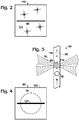
- Figure 2 shows a slit-forming optical element 110 of detection system 50 that creates optical slit 86.
- the slit is transparent for the optical radiation of the system, while an opaque body 112 around the slit prevents transmission of the optical radiation through optical element 110 elsewhere.
- Slit 86 may, for example, be created by an opening (an air gap) in body 112 or as an unmasked area on an otherwise masked surface of body 112.
- the slit is elongated orthogonal to optical path 77 followed by beam 76 at optical element 110, and elongated orthogonal to a direction of elongation of channel 60 (and fluid flow) through irradiation zone 66 (after correcting for a change in direction, if any, in the optical path between optical slit 86 and irradiation zone 66 (e.g., a change in direction created by a mirror)).
- Figure 3 shows irradiation zone 66 of channel 60 in more detail.
- Optical elements located in the optical path between slit 86 and channel 60 may collimate beam 76 and then focus the beam 76 on a section of the channel.
- the channel may be elongated in an image plane of slit 86 (see Figure 1 ), such that the slit is projected onto the section of the channel to create a volume within the channel that is irradiated by beam 76.
- This volume which is stippled distinctly in Figure 3 , is equivalent to irradiation zone 66, and may be described as a detection volume because the changing contents of this volume, as carrier fluid and particles flow through channel 60, may be a primary determinant of how much light is sensed by each detector over time.
- the width of slit 86 may, for example, be selected according to the diameter (or length) of particles 52 being detected, such that projected slit width 114 is less than the diameter (or length) of particles 52.
- the projected slit width is about 40-90%, 50-80%, or 60-70% of the particle diameter (or length).
- the length of the particles is defined in channel 60 as each particle passes through the irradiation zone.
- Figure 4 shows mask 90 of detection system 50.
- the mask may block any suitable transverse portion of the beam.
- the mask may be a line mask that provides a narrow, elongated, non-transmissive region, namely, a line 120 to block a portion of beam 76.
- Line 120 may be oriented parallel to optical slit 86, and may or may not be centered on beam 76 and/or optical axis 78.
- the mask may, for example, be formed by a transparent substrate 122 having an opaque coating to create an opaque line 120.
- substrate 122 may be formed of glass, and line 120 may be produced by chromium etching of an elongated surface region of the glass.
- the mask may be considered to be the entire optical element or only an opaque region thereof.
- the line mask may be created by a discrete elongated member, such as a thin wire.
- the mask may have a different shape of masking element, such as a non-elongated shape (e.g., a circle or square) to create a point mask.
- Line 120 may have any suitable size and position.
- the line may be longer than the diameter of beam 76, as shown in Figure 4 .
- the width of line 120 may be substantially less than the beam's diameter, such as less than about 20%, 10%, or 5%, among others, of the diameter.
- the line may block any suitable portion of the beam's cross-sectional area (and/or light), such as less than about 10%, 5%, or 2%, among others.
- Exemplary widths of line 120 include less than about 1 mm, 700 ⁇ m, or 400 ⁇ m, among others.
- Figure 5 shows an embodiment 130 of detection system 50.
- Beam 76 is stippled to illustrate how mask 90 blocks a portion of the beam to form a shadow region 132 (interchangeably termed a dark region) in the beam.
- Portions of the shadow region may be located optically upstream and downstream of the irradiation zone (and channel 60). However, in the depicted embodiment, the downstream portion provides a location for detection of deflected light.
- the shadow region may represent any suitable portion of a beam angle 134 defined by a diverging region of the beam extending away from channel 60 toward deflection detector 72.
- the shadow region may define a shadow region angle 136 of less than about 8, 6, 5, 4, 3, or 2 degrees.
- Deflection detector 72 has a photosensitive area 138 that is aligned with shadow region 132.
- An optical slit 140 defined by optical element 94 is sized and positioned to prevent undeflected light 142 of beam 76 from striking photosensitive area 138. In other words, optical slit 140 may be narrower than the width of shadow region 132 where the beam strikes optical element 94.
- Optical slit 140 may be located in the image plane of mask 90.
- Deflection detector 72 is positioned behind (downstream from) optical element 94 and its slit 140 and detects light from beam 76 that is deflected into the shadow region. A suitable position for slit 140 and/or deflection detector 72 may be determined by the proximity of mask 90 to the back focal plane of objective 92.
- the image plane for the mask is located at infinity behind channel 60. Accordingly, the mask can be positioned with an offset from the back focal plane to move the mask's image plane to a convenient distance from channel 60.
- Photosensitive area 138 of detector 72 may be positioned near the image plane of the mask, such as close to and directly behind slit 140.
- light that has passed through the irradiation zone, and particularly deflected light can be focused with an optical element, as described below in Example 1.
- the slit may be located in the mask's image plane. Moving the slit closer to or farther from the objective, and therefore out of the image plane, rapidly reduces contrast of the mask image and increases noise. The contrast is reduced because the slit has a finite width, and the light coming though it may not be perfectly collimated when incident on the mask.
- An idealized, masked beam pattern i.e., a sharp mask shadow at any downstream position, shown in Figure 1 , only may occur for a mask inserted in a perfectly collimated beam.
- a mask image formed in an image plane of mask may or may not be magnified or minified with respect the physical mask.
- the image of the mask is minified 0.5x relative to the physical mask. For example, if a line of the physical mask has a width of 300 ⁇ m, the width of the line in the mask image may be 150 ⁇ m.
- Detection system 130 illustrates additional exemplary aspects of system 50 of Figure 1 .
- system 130 incorporates an objective 92 formed by two or more lenses, which may be pre-assembled with one another to create a unit.
- the objective is a Meiji objective having 40x magnification, a numerical aperture of 0.6, and a working distance of 2.8 mm.
- a spatial filter 143 providing a 2x magnification is formed by lenses 84 and 88, and slit-forming optical element 110.
- fluidics subsystem 54 is designed to transport droplets 144 (as particles 52) through irradiation zone 66 in a channel-forming member 146 that is planar.
- the droplets are disposed in an immiscible carrier liquid 148 (e.g., oil).
- the separation, if any, between droplets approaching irradiation zone 66 may be increased by introduction of additional carrier fluid 150 from one or more dilution channels at a channel junction 154 that is fluidically upstream of irradiation zone 66.
- Channel member 146 also may have an inlet 156 for ingress of additional carrier fluid and an outlet 158 for egress of droplets 144 after passing through the irradiation zone.
- Figures 6-9 show exemplary deflection of light within detection system 50 as a particle (e.g., a droplet 144) passes through irradiation zone 66.
- a particle e.g., a droplet 14
- the entire droplet is outside of irradiation zone 66. No deflected light reaches deflection detector 72.
- a leading edge of the droplet has entered the irradiation zone, which produces deflected light 160 that enters shadow region 132 sufficiently to pass through optical slit 140 and reach detector 72.
- the droplet is roughly centered in the irradiation zone and produces deflected light 160 that enters shadow region 132 from both branches 162 of beam 76.
- each branch 162 also called a beam portion, may have about the same intensity if the line mask is centered on the beam.
- the trailing edge of the droplet has entered the irradiation zone, producing deflected light 160 that enters shadow region 132 sufficiently to pass through optical slit 140 and reach detector 72.
- This section describes exemplary aspects of the fluidics subsystem and exemplary carrier fluid and particles therein.
- the fluidics subsystem includes at least one channel 60 to contain and direct movement of carrier fluid and particles.
- the channel may have any suitable cross-sectional shape, such as circular, elliptical, or polygonal.
- the channel may have a cross-sectional dimension that is approximately the same as or greater than the diameter of the particles.
- the channel is a microfluidic channel, namely, a channel having a cross-sectional dimension less than about 1 mm.
- Exemplary channels have a length that is at least about 2, 5, 10, or 20 times the minimum cross-sectional dimension of the channel.
- the channel may be a circumferentially-enclosed passage defined in a planar member, or may be an enclosed passage defined inside a tube (e.g., a tube with a cylindrical exterior).
- the channel may be formed at least in part by molding, wet etching, dry etching, laser etching, or machining.
- the fluidics subsystem may include a source of negative pressure (a vacuum) to pull fluid along the channel, positive pressure to push fluid along the channel, or both.
- a source of negative pressure a vacuum
- the pressure may be created by a pump.
- the pump may be a positive-displacement pump, such as a syringe pump, among others.
- Other exemplary pumps include peristaltic pumps, or rotary pumps.
- the pressure may be provided by a container introduced to the system while holding pressurized gas or a vacuum.
- the carrier fluid may be any suitable liquid or gas phase capable of transporting the particles along the channel.
- the carrier fluid and the particles both may be liquid, for example, a dispersed liquid phase encapsulated by a continuous liquid phase, as in an emulsion.
- the carrier phase may include oil, and optionally a surfactant.
- Suitable oils may include a fluorine-containing oil, a silicone oil, or mineral oil, or any combination thereof, among others.
- the carrier phase may be a gas phase or a liquid phase and the particles may be solid-phase objects
- the carrier phase may be a gas phase and the particles may be droplets (e.g., as an aerosol)
- the carrier phase may be a liquid phase (e.g., an aqueous phase) or a gas phase and the particles may be biological cells.
- Particles detected by the detection system of the present disclosure may exist in any suitable phase, such as a liquid phase, a solid phase, or a combination thereof, among others.
- Exemplary particles include droplets, beads or other small solid-phase objects, and biological cells.
- Particles may have any suitable size. Generally, particles are less than about 1 mm in diameter and/or less than about 1 ⁇ l in volume. The particles may be at least about 1 ⁇ m in diameter and/or at least about 1 fl in volume.
- Particles may have any suitable shape. Exemplary shapes include spherical, cylindrical, bullet-shaped, irregular, or random. Droplets and other particles may have a size and/or shape sensitive to one or more parameters of the fluidics subsystem.
- the diameter and/or shape of the droplets may be influenced by the diameter of channel 60.
- the shape of the droplets may be spherical, and the droplets may have a diameter that is less than the diameter of channel 60. In other cases, the droplets may be elongated, with a diameter corresponding to the channel's diameter.
- the shape of the droplets also may be affected by the flow rate of the carrier fluid, which may determine how much the droplets are stretched or otherwise deformed as they pass through the irradiation zone.
- the droplets may have a surface layer that discourages deformation of the droplets, such that the droplets are relatively insensitive to deformation by the fluidics subsystem.
- the particles may be photoluminescent, namely, capable of emitting light when irradiated with excitation light of the appropriate wavelength.
- exemplary types of photoluminescence include fluorescence, and phosphorescence.
- Each particle may contain a photoluminophore, which is any atom, molecule, moiety, complex, or aggregate capable of photoluminescence.
- Suitable photoluminophores include fluorescent dyes, and quantum dots.
- the optical subsystem may incorporate any suitable number of light sources, such as 1, 2, 3, 4, or more.
- the light sources may be operated to produce optical radiation that reaches the irradiation zone at the same time or at different times (e.g., alternately or sequentially).
- Each light source may generate optical radiation of any suitable wavelength.
- each light source or at least two light sources may emit visible light (e.g., at a different wavelength from other light sources of the system), or at least two light sources may emit different types of optical radiation (e.g., one light source may emit ultraviolet radiation and another light source may emit visible light).
- the light source may incorporate at least one light-emitting element to generate light, and, optionally, one or more optical elements to collect and/or focus the generated light to form a beam.
- exemplary light sources and/or light-emitting elements include electroluminescent lamps (e.g., light-emitting diodes and lasers (such as laser diodes)), and high-intensity discharge lamps (e.g., a mercury arc lamp).
- LEDs include any solid-state device that generates light by electroluminescence, including semiconductor LEDs, organic LEDs, and/or polymer LEDs.
- Each detector also called an optical detector or photodetector, may include at least one photosensor configured to detect light of any suitable wavelength.
- the detector may be a point detector (e.g., a photodiode or photomultiplier) or an image detector.
- Exemplary image detectors include multi-pixel photon counters (MPCC) (e.g., silicon photomultipliers (SiPM)), charge-coupled device (CCD) sensors, or active pixel sensors (e.g., complementary metal-oxide-semiconductor (CMOS) sensors, N-type metal-oxide-semiconductor (NMOS) sensors).
- MPCC multi-pixel photon counters
- SiPM silicon photomultipliers
- CCD charge-coupled device
- active pixel sensors e.g., complementary metal-oxide-semiconductor (CMOS) sensors, N-type metal-oxide-semiconductor (NMOS) sensors.
- CMOS complementary metal-oxide-semicon
- the optical system disclosed herein may be utilized to perform a method of detecting a particle.
- the method steps presented in the section may be performed in any suitable order and combination, and may be modified by any other features and aspects disclosed herein.
- a beam of light may be generated.
- the beam may be generated with at least one light source and may, for example, contain visible light, optionally at least predominantly.
- optical radiation of the light beam may be generated with at least one light-emitting diode or at least one laser.
- the beam may be directed to a channel to create an irradiation zone in the channel where the beam intersects the channel.
- the channel may contain a carrier fluid flowing along the channel through the irradiation zone, with one or more particles disposed in the carrier fluid. Flow of the carrier fluid may move each of the particles through the irradiation zone, optionally serially.
- the flow of the carrier fluid may be driven by a pressure differential, which may be created by a pump.
- the beam may be spatially filtered upstream of the channel. Spatial filtering may be performed at least in part in a focal plane of an optical element(s) of the system.
- the size of the beam may be restricted by spatial filtering, optionally with an elongated slit, such as an air slit, through which light of the beam passes.
- the slit may be arranged orthogonal to the channel (as defined by the long axis of the channel at and around the irradiation zone).
- the beam may be collimated upstream of the slit and focused on the slit.
- the beam may be collimated again at a position downstream of the site at which the beam is spatially filtered and upstream of the channel.
- a transverse portion of the beam may be blocked upstream of the irradiation zone to create a shadow region.
- the shadow region may be created downstream of the region at which the beam is blocked.
- a mask may be used to create the shadow region.
- the mask may be disposed in a collimated region of the beam to block the portion of the beam.
- the beam may be focused on the irradiation zone in the channel using an objective composed of one or more optical elements. Focusing the beam may be performed on a partially blocked region of the beam created by blocking the beam.
- Light of the beam may be deflected by interaction with matter in the irradiation zone.
- the light may be deflected by a particle passing through the irradiation zone.
- the light may be deflected into the shadow region, and may be detected downstream of the irradiation zone.
- the particle passing through the irradiation zone may produce a temporary increase (a pulse) in the intensity of light detected in the shadow zone by a detector.
- the beam may be spatially filtered downstream of the channel, and upstream of the detector, with an optical slit operatively disposed in an optical path between the channel and the detector.
- Photoluminescence induced by the beam at the irradiation zone may be detected.
- the detection of photoluminescence may be epi-fluorescence in which excitation light and emitted light share an optical path followed in respective opposite directions to and from the irradiation zone.
- This example describes exemplary configurations for detecting deflected light in detection system 50 with deflection detector 72, with or without one or more optical elements located between irradiation zone 66 and the detector; see Figures 10-15 .
- Each of the configurations of this example may be incorporated into any of the detection systems of the present disclosure.
- Light may be deflected at the irradiation zone by various mechanisms including refraction, reflection, and Mie scattering.
- the relative contribution of each mechanism may be determined by particle size, shape, composition; carrier fluid properties; and the nature of the interface between each particle and the carrier fluid.
- a carrier fluid comprising oil
- small angle deflection by micelles and large molecules (e.g., proteins) inside a droplet and on its surface, and light refraction and multiple reflection at the interface between the droplet and the oil all may deflect optical radiation into the shadow region.
- the latter effects may deflect incident optical radiation by greater angles, to produce "large angle" deflection.
- the detection system may be configured to detect deflected light of interest from only a portion of the shadow region, to selectively include and exclude deflected light according to the deflection angle.
- Large angle deflection may create a uniform intensity distribution of light across the slit while small angle deflection may bleed around the slit edges. Accordingly, when small angle deflection is more informative about the particles, a portion of the large angle deflection that is located more central to the shadow region can be selectively excluded. Alternatively, small angle deflection closer to the edges of the shadow region can be selectively excluded when large angle deflection is more informative about the particles. With this approach, the background level of the deflection signal may be reduced to increase the sensitivity of the detection system.
- Figure 10 shows a modified version 130' of detection system 130 of Figure 5 .
- System 130' adds a relay lens 170 between irradiation zone 66 and deflection detector 72.
- the relay lens may be located in a focal plane of mask 90 and re-images mask 90 to a greater distance from the irradiation zone (also see Figure 5 ).
- slit-forming element 94 is located in an image plane of the mask at a position farther from the irradiation zone, which may be more convenient if space within system 50 near the irradiation zone is limited, and may increase contrast between the dark image of the mask and the area illuminated adjacent the image by beam 76.
- the aperture of relay lens 170 may be reduced to exclude the beam and, optionally, deflected light near opposite edges of the shadow region, to selectively exclude light deflected by only a small angle.
- the aperture of relay lens 170 may be increased such that a greater amount of large angle deflection is detected, optionally predominantly.
- the relay lens may have an aperture that renders slit-forming element 94 unnecessary.
- Figure 11 shows a fragmentary view of detection system 50 of Figure 1 , taken around flow channel 60 and deflection detector 72.
- the configuration of Figure 11 is presented here as a reference for comparison to the modified configurations of Figures 12-15 .
- Figure 12 shows a modified version 50a of the detection system of Figure 1 with reduced detection of small angle deflection.
- System 50a has a slit-forming element 94a at the same position along the optical path as element 94 of system 50, namely, in the image plane of mask 90 (see Figure 1 ), but defines a narrower optical slit 140a. Accordingly, the width of the slit may be adjusted to reduce background.
- Figure 13 shows yet another modified version 50b of detection system 50.
- System 50b replaces detector 72 with a detector 72b having a smaller photosensitive area 138b.
- Area 138b may be located in the image plane of mask 90 (see Figure 1 ), in place of optical slit 140 (compare with Figure 11 ).
- the photosensitive area may be sized and positioned such that no portion of beam 76 is incident on area 138b (or detected). Instead, only light deflected in irradiation zone 66 can reach area 138b and be detected.
- the size and aspect ratio of area 138b may be selected to at least generally match that of the shadow region in the image plane of the mask.
- area 138b may be elongated parallel to optical slit 86 and/or parallel to a line of mask 90.
- Area 138b may have an aspect ratio of at least about 5:1, or 10:1, among others.
- the width of area 138b may be selected to include or exclude small angle deflection.
- Figure 14 shows still another modified version 50c of detection system 50.
- System 50c is created from system 50 by replacement of downstream optical slit 140 with a slit-forming element 94c having a pair of optical slits 140c that are parallel to one another.
- the pair of optical slits each may be located in the image plane of mask 90 (see Figure 1 ) and may be separated by a masking region 180.
- Masking region 180 reduces detection of large angle deflection.
- another optical slit may be disposed between optical slit 140 of Figure 11 and detector 72.
- Figure 15 shows yet still another modified version 50d of detection system 50.
- a mask 190 is attached to the deflection detector and covers portions of photosensitive area 138.
- Mask 190 may be located out of the mask's image plane. Accordingly, there may be no good correlation between a point on area 138 and the deflection angle of light that can reach that point. However, extra masking or baffling of detector 72 may be effective to control some undesired light that could be present due to light deflection that occurs outside of the detection volume, for example, from an outer surface region of a channel-forming member or various imperfections.
- This example describes intensity distributions calculated with optical modeling software for an exemplary detection system 200; see Figures 16-18 .
- Figure 16 shows detection system 200 having a deflection detector 72 sized and positioned to be illuminated by the full cross-section of beam 76.
- Detector 72 may be an imaging detector configured to detect beam 76 and shadow region 132. Light deflected into the shadow region may be detected as an increased intensity for image pixels representing the shadow region.
- Figure 17 shows a calculated intensity distribution of light in irradiation zone 66 of detection system 200, in a plane orthogonal to the optical path of the beam and bisecting the irradiation zone.
- the intensity distribution was calculated with Zemax ® software for a 100 x 100 ⁇ m region of the plane. Irradiance levels within the image are defined by the scale to the right of the image. Opposite wall regions 210 of channel 60, which delineate part of the irradiation zone, are indicated with dashed lines.
- Figure 18 shows a calculated intensity distribution of light detected by detector 72 of detection system 200.
- the intensity distribution was calculated with Zemax ® software for a 2 x 2 mm square region of the detector. Irradiance values within the image are defined by the scale to the right of the image. Beam 76, shadow region 132, and separate beam portions (branches 162) of the beam are indicated.
- Detection system 130 has a light source 70 (e.g., an LED) and a pair of photoluminescence detectors 74a, 74b each optically coupled to spatial filter 143 and objective 92, in part, by a light guide 220a or 220b.
- Each of the light guides includes an optical fiber 222 that allows the optical paths for excitation and emission to bend, as needed.
- Excitation light produced by light source 70 passes, in order, through light guide 220a, a collimating lens 224, and a spectral filter 226a.
- the excitation light then is reflected toward spatial filter 143 by a beam splitter 82 (here, a long-pass mirror), and propagated through objective 92 and irradiation zone 66, for excitation of a photoluminophore(s) therein and deflection.
- a beam splitter 82 here, a long-pass mirror
- Light emitted from irradiation zone 66 travels in reverse through objective 92, spatial filter 143, beam splitter 82, a spectral filter 226b, a focusing lens 228, light guide 220b, and a collimating lens 230.
- a portion of the collimated, emitted light then passes through a beam splitter 82a to a focusing light guide 232a and detector 74a.
- Another portion of the collimated, emitted light is reflected by beam splitter 82a to focusing light guide 232b and detector 74b.
- Detection system 130 may incorporate one or more additional light sources and/or one or more additional photoluminescence detectors. Accordingly, the detection system may be configured to detect photoluminescence in only one channel with one detector, at least two channels with two detectors (as shown in Figure 19 ), or three or more channels with three or more detectors, among others.
- This example describes exemplary deflection and photoluminescence data collected from droplets with a working model of detection system 130; see Figure 20 .
- Droplets containing a pair of fluorescent dyes were generated.
- the dyes emit light that is detectable with detectors 74a and 74b, respectively (see Figure 19 ).
- the signals registered by detectors 74a and 74b are designated as channel 1 (CH1) and channel 2 (CH2) fluorescence, respectively, in Figure 20 .
- a deflection signal was detected by detector 72 synchronously with detection of the signals of the two fluorescence channels by detectors 74a and 74b.
- the intensity of each signal was plotted as a function of time as four droplets were passed through the irradiation zone. Portions of the signals representing the four well-separated droplets are indicated by the letters A, B, C, and D, in Figure 20 .
- Figure 20 shows the deflection signal rising from baseline as the leading edge of each droplet enters the irradiation zone, indicated by a dashed line at 240, and returning to baseline upon exit of the trailing edge of the droplet from the irradiation zone, indicated by a dashed line at 242, to define a transit interval or span 244 for the droplet.
- Variations in the deflection signal caused by the droplet during the transit interval create a droplet waveform 246.
- the waveform includes at least one peak (i.e., a local maximum) and may, as shown, include a leading peak 248 (a first local maximum (a first height)) and a trailing peak 250 (a second local maximum (a second height)) to form a double peak (two local maxima).
- the waveform may have a signature characteristic of a droplet or other particle.
- Peaks 248, 250 may be created by corresponding leading and trailing regions of the droplet (and corresponding waveform), particularly a pair of humps 252, 254 formed by the leading and trailing regions of the droplet.
- the humps may create a valley 256 (a local minimum) located temporally intermediate the pair of peaks.
- Any suitable characterizing value(s) calculated from the waveform and/or features thereof may contribute to analysis of droplet size, droplet shape, and/or flow velocity of fluid through the irradiation zone.
- the characterizing values of a waveform may include the width/time interval of the waveform measured at baseline, and/or at one-half the maximum amplitude or waveform height, among others.
- the characterizing values also or alternatively may include a separation value 258 corresponding to a temporal separation between the peaks within the waveform.
- the characterizing values also or alternatively may include a relative size (height and/or width) of the leading and trailing regions of the waveform relative to one another, a ratio of a peak or waveform height and the local minimum between peaks, and/or a period between waveforms.
- This example describes further exemplary aspects of particle detection systems.
- the detection system may be based on focused light of any detectable wavelength being deflected by a particle, such as a droplet, while the particle is in the detection volume.
- a particle such as a droplet
- at least three mechanisms e.g., Mie scattering, refraction, and reflection
- the detection of deflected light may be accompanied with measuring the fluorescence intensity originating from dye molecules inside particles, such as droplets.
- the same light source may be used to generate deflection and fluorescence signals, and thus optical radiation from the light source may be referred to as excitation light. Processing of synchronously-acquired deflection and fluorescence signals increases the accuracy of the amplitude and span of the fluorescence signal of each particle, in particular for particles having only weak (or no) fluorescence.
- the detection system is based on blocking a fraction of the collimated excitation light before it is focused by an objective into a detection volume.
- An air slit and the magnification produced by a collimating lens and a focusing objective may define a detection volume inside a flow channel.
- a line mask may be located at the back focal plane of the focusing objective or, when the back focal plane is inaccessible, as close to it as possible. Most large-magnification objectives have the back focal plane inside their bodies. Testing was performed with a line mask constituted by a thin, straight black wire. The wire was mounted to the back aperture of the focusing objective. The direction of the wire was aligned with the direction of the air slit.
- the focusing objective creates an image of the line mask at a certain distance behind the detection volume.
- Another air slit may block light outside of the shadow region, and a light detector may detect light intensity right behind the air slit.
- the air slit in front of the deflection detector may be selected to have its width slightly narrower than the line mask image and its direction may be aligned with the direction of the line mask image.
- the deflection detector stays in darkness until a particle enters the detection volume. The presence of the particle changes the paths of light rays across the detection volume and some light reaches the deflection detector, creating a deflection signal.
- the disclosed detection scheme is different from the layout of a forward scattering channel used in many flow cytometers.
- a narrow laser beam focused with a relatively long focal length lens (e.g., 50-100 mm) into a flow channel, is entirely blocked with an opaque optical stop at the other side of the channel, while small angle scattered light is detected around the stop.
- the detection system disclosed herein has various advantages over flow cytometers having a forward scattering channel.
- First there may be no need to use a high quality laser beam, i.e., a beam that is both narrow and well-collimated.
- the optical detection system disclosed herein was tested with low-cost, high-power LEDs coupled to multimode optical fibers, as well as with diode lasers coupled to the same multimode optical fibers, and demonstrated comparable performance with the different light sources.
- any light source that can be coupled into a large-core optical fiber and then collimated may be suitable for the detection of deflected light, as described herein.
- Second there may be no need to use a second objective to collect fluorescence.
- a separate high numerical aperture objective mounted at 90 degrees with respect to the excitation laser optical path collects light emitted by fluorescence.
- the focusing objective of the present disclosure may be configured to have a short working distance and high numerical aperture, which allows construction of an epi-fluorescence confocal layout, as shown in Figure 1 , where the same objective focuses the irradiation/excitation beam on the detection volume and collects light emitted by fluorescence.
- the registered fluorescence amplitudes shown in Figure 20 were acquired in an epi-fluorescence confocal mode.
- a black line mask at the main objective back aperture creates a shadow across the illuminated area at the opposite side of a flow chip (a planar member defining a flow channel).
- the shadow half angle is two degrees.
- a photodiode with an air slit in front of it normally stays in the shadow. Once a droplet enters the detection volume, the droplet deflects some of the excitation light, which passes through the slit and generates photocurrent. With a droplet-diameter-to-wavelength ratio around 100, Mie theory predicts negligible scattering at angles above two degrees, so the detection mechanism may be based on droplet "lensing" due to a lower refractive index of water (1.33) than silicone oil (1.39).
- the mask preferentially may be a long line due to a round flow channel serving as a negative power cylindrical lens, such that a round spot mask (a point mask) creates little shadow.
- the mask does not interfere with the image formation of a telescope's slit, i.e., the detection area is still a sharp, uniformly-illuminated line. Total light losses due to both excitation light and fluorescence being masked by the mask may stay below 5, 4, 3, or 2 percent.
Description
- Relevant prior art for this application are following documents:
WO 2013/189921 A1 (SIEMENS AG [DE]) 27 December 2013 ;US 2014/370586 A1 (SEO KATSUHIRO [JP] ET AL) 18 December 2014 ;U.S. Patent Application Publication No. 2010/0173394 A1, published July 8, 2010 ; and Joseph R. Lakowicz, PRINCIPLES OF FLUORESCENCE SPECTROSCOPY (2nd Ed. 1999). - A signal is detected from particles in various types of assays. The particles may be solid-phase particles (e.g., beads), liquid-phase particles (droplets), or biological cells, among others. In a typical assay, the particles are labeled with a fluorescent dye. Fluorescence then is detected from individual particles as the particles are passed serially through a detection volume where the fluorescent dye is excited to cause light emission.
- Fluorescence alone may be inadequate to accurately detect the presence of each particle and characterize the particle's size/shape. This problem can be significant in a mixed population of particles each having high or low fluorescence, as in many digital assays, and/or when some of the particles should be ignored for being too large or small or for having an aberrant shape. Accordingly, the result of a particle-based assay may be skewed by overestimating or underestimating the number of particles detected, failing to exclude fluorescence data for particles that do not meet size/shape criteria, and the like.
- Cell sorting instruments have been developed that detect light scattering by, and fluorescence from, biological cells traveling through a flow cell. The ability of each cell to scatter light allows the presence of the cell to be detected, while a fluorescence signal detected from the cell provides further characterization. The instrument utilizes a laser beam to irradiate a region of the flow cell, and positions an opaque optical stop behind the flow cell. The stop blocks undeflected light of the beam, while scattered light bypasses the optical stop and is detected by a scattering detector located beyond the optical stop. A condenser with a long focal length focuses the laser beam onto the flow cell, which makes epi-fluorescence detection impractical. Instead, light emitted by fluorescence is collected and detected in an optical path extending from the flow cell in a direction orthogonal to the excitation path followed by the laser beam to the flow cell.
WO 2013/189921 discloses a detection system for particles, comprising a channel; a light source configured to generate light; one or more optical elements configured to focus a beam of the light on an irradiation zone within the channel; a mask operatively disposed in an optical path between the light source and the channel, wherein the mask is configured to block a portion of the beam, thereby producing a shadow region; and a detector configured to detect light deflected from the beam into the shadow region by interaction with a particle passing through the irradiation zone. Further,US 2014/0370586 discloses a microchip including an incident surface configured to receive light transmitted from a light source, the light being received from an incident direction and a back surface that is opposite the incident surface, the back surface including a portion that is configured to reflect light transmitted from the light source away from the incident direction. - The design of these cell sorting instruments has various disadvantages. For example, the laser is expensive and can make the instrument unaffordable for a typical laboratory. Also, the flow cell must be optically accessible on three sides, which severely limits the options for replacing the flow cell with a different fluidic member.
- The present disclosure provides an optical detection system and method for particles as defined in
claims 1 and 8. The detection system for particles comprises a channel; a light source configured to generate light; one or more optical elements configured to focus a beam of the light on an irradiation zone within the channel; a mask operatively disposed in an optical path between the light source and the channel, wherein the mask is configured to block a portion of the beam, thereby producing a shadow region; a first detector configured to detect light deflected from the beam into the shadow region by interaction with a particle passing through the irradiation zone; and a second detector configured to detect photoluminescence induced by the beam in the irradiation zone; wherein the one or more optical elements provide an objective that collects emitted light from the irradiation zone for propagation to the second detector; and wherein the same light source generates light deflected by the particle at the irradiation zone and detected by the first detector, and excitation light that induces photoluminescence in the irradiation zone for detection by the second detector. Further, the method of detecting a particle comprises generating a beam of light; blocking a portion of the beam optically upstream of a channel to produce a shadow region; focusing the beam on an irradiation zone within the channel; passing a particle through the irradiation zone, wherein the step of passing deflects light into the shadow region by interaction with the particle; spatially filtering light of the beam with an optical slit disposed in an optical path between the channel and a first detector; detecting light in the shadow region using the first detector, wherein the light detected in the shadow region is not focused between the channel and the first detector; and detecting, with a second detector, photoluminescence induced by the beam at the irradiation zone. -
-
Figure 1 is a schematic view of an exemplary optical detection system for detecting and characterizing particles, such as droplets, in accordance with aspects of the present disclosure. -
Figure 2 is a view of a slit-forming optical element of the detection system ofFigure 1 , taken generally along line 2-2 ofFigure 1 . -
Figure 3 is a fragmentary view of the detection system ofFigure 1 , taken where a light beam intersects a flow channel to create an irradiation zone, also called a detection volume. -
Figure 4 is a view of a mask of the detection system ofFigure 1 , taken generally along line 4-4 ofFigure 1 . -
Figure 5 is a fragmentary, schematic view of an embodiment of the detection system ofFigure 1 , with the beam of light stippled to illustrate how a mask forms a shadow region in the beam, in accordance with aspects of the present disclosure. -
Figures 6-9 are a temporal series of fragmentary views of the detection system ofFigure 1 , taken as a particle (e.g., a droplet) passes through the detection volume of the system and illustrating how incident light may be deflected by different regions of the particle, in accordance with aspects of the present disclosure. -
Figure 10 is a modified version of the detection system ofFigure 4 created by addition of a relay lens to focus deflected light and move an image plane of the mask farther from the channel, in accordance with aspects of the present disclosure. -
Figure 11 is a fragmentary view of the detection system ofFigure 1 taken around a flow channel and a deflection detector of the system. -
Figure 12 is a fragmentary view of a modified version of the detection system ofFigure 1 , taken as inFigure 11 and having a narrower optical slit between the flow channel and the deflection detector, to reduce detection of small angle deflection. -
Figure 13 is a fragmentary view of another modified version of the detection system ofFigure 1 , taken as inFigure 11 and having a deflection detector with a smaller photosensitive area located in the image plane of the mask and replacing the optical slit ofFigure 11 . -
Figure 14 is a fragmentary view of still another modified version of the detection system ofFigure 1 , taken as inFigure 11 and having a pair of optical slits located in the image plane of the mask to reduce detection of large angle deflection. -
Figure 15 is a fragmentary view of yet another modified version of the detection system ofFigure 1 , taken as inFigure 11 and having a portion of the deflection detector masked to reduce detection of undesired light. -
Figure 16 is a fragmentary view of an embodiment of the detection system ofFigure 1 configured to detect deflected light and undeflected light at a position downstream of the irradiation zone of the channel. -
Figure 17 is a calculated intensity distribution of light within the detection system ofFigure 16 for a region indicated generally by line 17-17 inFigure 16 and located in and around the irradiation zone. -
Figure 18 is a calculated intensity distribution of light incident on a detector of the system ofFigure 16 at the region indicated generally by line 18-18 inFigure 16 . -
Figure 19 is a more complete view of the detection system ofFigure 5 , with the view including a light source and a pair of photoluminescence detectors. -
Figure 20 is a graph of the intensity of deflected light and fluorescence detected with a working model of the detection system ofFigure 19 , as a function of time from a series of droplets traveling through the irradiation zone of a channel. - The present invention provides an optical detection system and method for particles as defined hereinbefore. The system comprises a channel, a light source configured to generate light, and one or more optical elements configured to focus a beam of the light on an irradiation zone within the channel. The system also comprises a mask operatively disposed in an optical path between the light source and the channel. The mask is be configured to block a portion of the beam, thereby producing a shadow region. The system further comprises a detector configured to detect light deflected from the beam into the shadow region by interaction with a particle passing through the irradiation zone.
- In some embodiments, the system may comprise an optical slit operatively disposed in an optical path between the light source and the channel. At least one collimating element may be operatively disposed in the optical path upstream of the mask, such that the mask intersects a collimated region of the beam. The mask may be a line mask having an elongated masking region oriented parallel to the optical slit and configured to block a portion of the collimated region of the beam. One or more focusing elements may be operatively disposed in an optical path between the mask and the channel and configured to focus the beam on the irradiation zone. Furthermore, the particle may be a droplet, a solid-phase particle, or a biological cell. In some embodiments, the particle may be a droplet suspended in an immiscible carrier liquid.
- An exemplary method of detecting a particle is provided. In the method, a beam of light may be generated. A transverse (cross-sectional) portion of the beam may be blocked optically upstream of a channel to produce a shadow region. The beam may be focused on an irradiation zone within the channel. A particle may be passed through the irradiation zone. The step of passing may deflect light into the shadow region by interaction with the particle. Deflected light may be detected in the shadow region. The step of passing may cause more light to be detected temporarily, optionally as a pulse of increased light intensity.
- The method may be defined further. The step of focusing may be performed on a partially blocked region of the beam that results from the step of blocking. The step of blocking may be performed on a collimated region of the beam. The method further may comprise a step of passing light of the beam through an optical slit operatively disposed such that the step of passing light is performed optically upstream of the step of blocking a portion of the beam. The beam may include optical radiation emitted by a light-emitting diode. The step of blocking may be performed with a line mask. The line mask may have a masking region elongated orthogonal to the channel. The masking region may be elongated parallel to an optical slit operatively disposed upstream of the line mask. The step of detecting may be performed with a detector, and the method further may comprise a step of spatially filtering light of the beam with an optical slit disposed in an optical path between the channel and the detector. The method further may comprise a step of detecting photoluminescence induced by the beam at the irradiation zone. The step of passing a particle may include a step of passing a droplet through the irradiation zone. The step of blocking may be performed with a mask, and the step of detecting may detect light received from an optical slit located in an image plane of the mask. The step of detecting may be performed with a detector, and the light detected in the shadow region may not be focused between the channel and the detector.
- Further aspects of the present invention are described in the following sections: (I) detection system overview, (II) fluidics subsystem, (III) optical subsystem, (IV) methods of particle detection, and (V) examples.
- This section provides an overview of an
exemplary detection system 50 for optically detecting and/or characterizingparticles 52, such as droplets; seeFigures 1-8 .Detection system 50 may include afluidics subsystem 54, anoptical subsystem 56, and a processing/control subsystem 58. -
Fluidics subsystem 54 may incorporate achannel 60 at which the fluidics subsystem intersects the optical subsystem. The channel defines a flow path for travel, indicated by a motion arrow at 62, ofparticles 52 and a surrounding carrier fluid 64. The flow path extends through anirradiation zone 66 within the channel. (Theirradiation zone 66 interchangeably may be called a detection volume, as explained below.) The fluidics subsystem also includes a drive mechanism operatively connected to the channel and including one or more sources of positive/negative pressure. Each source of positive/negative pressure may, for example, include at least onepump 68 that is operatively connected to the channel, to create a pressure differential that drives flow of the carrier fluid alongchannel 60 and throughirradiation zone 66. The pump may be a positive pressure pump or a negative pressure pump (i.e., a vacuum pump). Fluid communication between the pump and the channel may be controlled by one or more valves located in a fluid path between the pump and the channel. -
Particles 52 are transported by the carrier fluid through the irradiation zone. The carrier fluid may be supplied by a source of carrier fluid that is in fluid communication with the channel. In some embodiments, the particles may be droplets, such as aqueous droplets, and the carrier fluid may be a continuous phase, such as oil, composed of liquid that is immiscible with the droplets. -
Optical subsystem 56 includes at least onelight source 70, at least one light detector (e.g., adeflection detector 72 and a photoluminescence detector 74), and various optical elements to direct and/or restrict travel of optical radiation from the light source(s) toirradiation zone 66, and from the irradiation zone to the detector(s).Light source 70 generates abeam 76 of optical radiation, which may, for example, be diverging, collimated, or converging in regions along the beam, according to the optical elements disposed in the path of the beam. The optical subsystem may incorporate any suitable optical elements, such as lenses, masks, spatial/spectral filters, mirrors, aperture-defining elements, beam splitters, and light guides. For example, one or more spectral filters may be disposed in an optical path between the irradiation zone and the photoluminescence detector to selectively prevent excitation light (relative to light emitted by photoluminescence) from reaching the detector. - The terms "light" and "optical radiation" are used interchangeably herein. Either term denotes ultraviolet radiation, visible light, or infrared radiation, or any combination thereof.
-
Beam 76 follows on anoptical path 77 extending downstream fromlight source 70, acrosschannel 60, and towarddeflection detector 72. The optical path defines anoptical axis 78 that may be linear, as shown here, or may be bent (e.g., via a light guide and/or a mirror) (see Example 3). In the depicted embodiment, following the beam fromlight source 70 alongoptical path 77,beam 76 diverges, is collimated by a collimatinglens 80, extends through a beam splitter 82 (here, a short-pass mirror), and is focused by a focusinglens 84. The focused beam extends through anoptical slit 86, is collimated by another collimatinglens 88, and partially blocked bymask 90. The beam is focused by at least one focusing element onirradiation zone 66 ofchannel 60. The focusing element(s) may be described as a condenser and as an objective. The focusing element(s) functions as a condenser for optical radiation ofbeam 76 traveling from left to right inFigure 1 alongoptical path 77, and as an objective for emitted light traveling in reverse, from right to left inFigure 1 , along only a portion of the optical path. The focusing element(s) is called objective 92. - At any given time, optical radiation incident on
irradiation zone 66 may follow different trajectories. Most of the optical radiation of the beam may pass throughirradiation zone 66 substantially undeflected. This undeflected optical radiation is not incident on the photosensitive region ofdeflection detector 72. For example, this undeflected optical radiation may be prevented from reachingdetector 72 by a spatial filter, namely, an aperture-defining element (e.g., a slit-forming element 94), or may be too divergent from the optical path todetector 72. A fraction of the optical radiation may be deflected sufficiently toward the deflection detector by the current contents of the irradiation zone, such that the deflected radiation is incident on a photosensitive area of the detector and thus is detected. Another fraction of the optical radiation may excite a photoluminophore(s) within the irradiation zone, causing emission of photons (i.e., photoluminescence). - A portion of this emitted light may be detected by
photoluminescence detector 74, after travel in reverse along a portion ofoptical path 77. In particular, the emitted light passes through objective 92, collimating (now focusing)lens 88,optical slit 86, and focusing (now collimating)lens 84. When the emitted light (of longer wavelength than the excitation light of beam 76) reachesbeam splitter 82, the light is reflected to a focusinglens 96, indicated by an arrow at 98, which focuses the emitted light onphotoluminescence detector 74. Accordingly, optical radiation from the samelight source 70 may be deflected towarddeflection detector 72 and may cause photoluminescence. - The term "deflect," as used herein, means cause to change course or follow a new trajectory. More specifically, optical radiation deflected by interaction with matter (e.g., a particle and/or carrier fluid) in an irradiation zone deviates from a current trajectory as a consequence of the interaction. Deflection may occur by any suitable mechanism or combination of mechanisms. Exemplary deflection mechanisms pertinent to the detection system disclosed herein may include refraction, reflection, and Mie scattering. In some embodiments, such as with transparent particles, a difference in refractive index between the particles and the carrier fluid may be responsible for a majority of the detected deflection.
- To facilitate description, light can be considered to travel in the beam along an optical path from positions optically "upstream" to positions optically "downstream." Accordingly, the relative position of optical elements in the optical path also can be described with these two terms. For example, in
Figure 1 ,light source 70 is upstream ofoptical slit 86, which, in turn, is upstream ofmask 90. The mask is upstream of objective 92 andirradiation zone 66.Deflection detector 72 and slit-formingelement 94 are downstream ofirradiation zone 66, and slit-formingelement 94 is upstream ofdetector 72. - Processing/
control subsystem 58 may be in communication with and/or operatively connected to any suitable components of the fluidics subsystem and/or the optical subsystem, as indicated byarrows 100. For example,subsystem 58 may receive a deflection signal detected bydeflection detector 72 and/or a photoluminescence signal detected byphotoluminescence detector 74.Subsystem 58 may include a processor 102 (e.g., an electronic/digital processor) configured to process the deflection signal and/or the photoluminescence signal to determine one or more characteristics ofparticles 52. The characteristics may include a size, velocity, shape, transit time through the irradiation zone, presence or absence of an analyte in or on individual particles.Processor 102 also or alternatively may control operation ofpump 68,light source 70, or one or bothdetectors -
Processor 102 may include a memory and a data manipulation program stored in the memory. The data manipulation program may include instructions stored in memory and executable by the processor to control and/or perform any of the steps of the present method. -
Figure 2 shows a slit-formingoptical element 110 ofdetection system 50 that createsoptical slit 86. The slit is transparent for the optical radiation of the system, while anopaque body 112 around the slit prevents transmission of the optical radiation throughoptical element 110 elsewhere.Slit 86 may, for example, be created by an opening (an air gap) inbody 112 or as an unmasked area on an otherwise masked surface ofbody 112. The slit is elongated orthogonal tooptical path 77 followed bybeam 76 atoptical element 110, and elongated orthogonal to a direction of elongation of channel 60 (and fluid flow) through irradiation zone 66 (after correcting for a change in direction, if any, in the optical path betweenoptical slit 86 and irradiation zone 66 (e.g., a change in direction created by a mirror)). -
Figure 3 showsirradiation zone 66 ofchannel 60 in more detail. Optical elements located in the optical path betweenslit 86 andchannel 60 may collimatebeam 76 and then focus thebeam 76 on a section of the channel. The channel may be elongated in an image plane of slit 86 (seeFigure 1 ), such that the slit is projected onto the section of the channel to create a volume within the channel that is irradiated bybeam 76. This volume, which is stippled distinctly inFigure 3 , is equivalent toirradiation zone 66, and may be described as a detection volume because the changing contents of this volume, as carrier fluid and particles flow throughchannel 60, may be a primary determinant of how much light is sensed by each detector over time. - The width of
slit 86 and the magnification or minification, if any, created by optical elements between the slit andirradiation zone 66, define a projectedwidth 114 of the slit inchannel 60. Projectedslit width 114, measured parallel to along axis 116 of the channel, determines the size ofirradiation zone 66 within the channel. For example, ifslit 86 has a width of 35 µm, and the optical subsystem has a magnification of two betweenslit 86 andchannel 60, projectedwidth 114 is 70 µm. Accordingly, the width ofslit 86 may, for example, be selected according to the diameter (or length) ofparticles 52 being detected, such that projectedslit width 114 is less than the diameter (or length) ofparticles 52. In exemplary embodiments, the projected slit width is about 40-90%, 50-80%, or 60-70% of the particle diameter (or length). The length of the particles is defined inchannel 60 as each particle passes through the irradiation zone. -
Figure 4 showsmask 90 ofdetection system 50. The mask may block any suitable transverse portion of the beam. For example, the mask may be a line mask that provides a narrow, elongated, non-transmissive region, namely, aline 120 to block a portion ofbeam 76.Line 120 may be oriented parallel tooptical slit 86, and may or may not be centered onbeam 76 and/oroptical axis 78. The mask may, for example, be formed by atransparent substrate 122 having an opaque coating to create anopaque line 120. For example,substrate 122 may be formed of glass, andline 120 may be produced by chromium etching of an elongated surface region of the glass. The mask may be considered to be the entire optical element or only an opaque region thereof. In some examples, the line mask may be created by a discrete elongated member, such as a thin wire. In some examples, the mask may have a different shape of masking element, such as a non-elongated shape (e.g., a circle or square) to create a point mask. -
Line 120 may have any suitable size and position. The line may be longer than the diameter ofbeam 76, as shown inFigure 4 . The width ofline 120 may be substantially less than the beam's diameter, such as less than about 20%, 10%, or 5%, among others, of the diameter. The line may block any suitable portion of the beam's cross-sectional area (and/or light), such as less than about 10%, 5%, or 2%, among others. Exemplary widths ofline 120 include less than about 1 mm, 700 µm, or 400 µm, among others. -
Figure 5 shows anembodiment 130 ofdetection system 50.Beam 76 is stippled to illustrate howmask 90 blocks a portion of the beam to form a shadow region 132 (interchangeably termed a dark region) in the beam. Portions of the shadow region may be located optically upstream and downstream of the irradiation zone (and channel 60). However, in the depicted embodiment, the downstream portion provides a location for detection of deflected light. The shadow region may represent any suitable portion of abeam angle 134 defined by a diverging region of the beam extending away fromchannel 60 towarddeflection detector 72. For example, the shadow region may define ashadow region angle 136 of less than about 8, 6, 5, 4, 3, or 2 degrees. -
Deflection detector 72 has aphotosensitive area 138 that is aligned withshadow region 132. Anoptical slit 140 defined byoptical element 94 is sized and positioned to preventundeflected light 142 ofbeam 76 from strikingphotosensitive area 138. In other words,optical slit 140 may be narrower than the width ofshadow region 132 where the beam strikesoptical element 94.Optical slit 140 may be located in the image plane ofmask 90.Deflection detector 72 is positioned behind (downstream from)optical element 94 and itsslit 140 and detects light frombeam 76 that is deflected into the shadow region. A suitable position forslit 140 and/ordeflection detector 72 may be determined by the proximity ofmask 90 to the back focal plane of objective 92. If the mask is placed in this focal plane, the image plane for the mask is located at infinity behindchannel 60. Accordingly, the mask can be positioned with an offset from the back focal plane to move the mask's image plane to a convenient distance fromchannel 60.Photosensitive area 138 ofdetector 72 may be positioned near the image plane of the mask, such as close to and directly behindslit 140. Alternatively, or in addition, light that has passed through the irradiation zone, and particularly deflected light, can be focused with an optical element, as described below in Example 1. - In order to achieve a high signal-to-noise ratio, the slit may be located in the mask's image plane. Moving the slit closer to or farther from the objective, and therefore out of the image plane, rapidly reduces contrast of the mask image and increases noise. The contrast is reduced because the slit has a finite width, and the light coming though it may not be perfectly collimated when incident on the mask. An idealized, masked beam pattern (i.e., a sharp mask shadow at any downstream position), shown in
Figure 1 , only may occur for a mask inserted in a perfectly collimated beam. - A mask image formed in an image plane of mask may or may not be magnified or minified with respect the physical mask. In the depicted embodiment, the image of the mask is minified 0.5x relative to the physical mask. For example, if a line of the physical mask has a width of 300 µm, the width of the line in the mask image may be 150 µm.
-
Detection system 130 illustrates additional exemplary aspects ofsystem 50 ofFigure 1 . For example,system 130 incorporates an objective 92 formed by two or more lenses, which may be pre-assembled with one another to create a unit. In the depicted embodiment, the objective is a Meiji objective having 40x magnification, a numerical aperture of 0.6, and a working distance of 2.8 mm. Aspatial filter 143 providing a 2x magnification is formed bylenses optical element 110. Also,fluidics subsystem 54 is designed to transport droplets 144 (as particles 52) throughirradiation zone 66 in a channel-formingmember 146 that is planar. The droplets are disposed in an immiscible carrier liquid 148 (e.g., oil). The separation, if any, between droplets approachingirradiation zone 66 may be increased by introduction ofadditional carrier fluid 150 from one or more dilution channels at achannel junction 154 that is fluidically upstream ofirradiation zone 66.Channel member 146 also may have aninlet 156 for ingress of additional carrier fluid and anoutlet 158 for egress ofdroplets 144 after passing through the irradiation zone. -
Figures 6-9 show exemplary deflection of light withindetection system 50 as a particle (e.g., a droplet 144) passes throughirradiation zone 66. InFigure 6 , the entire droplet is outside ofirradiation zone 66. No deflected light reachesdeflection detector 72. InFigure 7 , a leading edge of the droplet has entered the irradiation zone, which produces deflected light 160 that entersshadow region 132 sufficiently to pass throughoptical slit 140 and reachdetector 72. InFigure 8 , the droplet is roughly centered in the irradiation zone and produces deflected light 160 that entersshadow region 132 from bothbranches 162 ofbeam 76. (Eachbranch 162, also called a beam portion, may have about the same intensity if the line mask is centered on the beam.) InFigure 9 , the trailing edge of the droplet has entered the irradiation zone, producing deflected light 160 that entersshadow region 132 sufficiently to pass throughoptical slit 140 and reachdetector 72. - Further aspects of exemplary assays with, and detection systems for, droplets are described in
U.S. Patent Application Publication No. 2010/0173394 A1, published July 8, 2010 . - This section describes exemplary aspects of the fluidics subsystem and exemplary carrier fluid and particles therein.
- The fluidics subsystem includes at least one
channel 60 to contain and direct movement of carrier fluid and particles. The channel may have any suitable cross-sectional shape, such as circular, elliptical, or polygonal. The channel may have a cross-sectional dimension that is approximately the same as or greater than the diameter of the particles. In exemplary embodiments, the channel is a microfluidic channel, namely, a channel having a cross-sectional dimension less than about 1 mm. Exemplary channels have a length that is at least about 2, 5, 10, or 20 times the minimum cross-sectional dimension of the channel. The channel may be a circumferentially-enclosed passage defined in a planar member, or may be an enclosed passage defined inside a tube (e.g., a tube with a cylindrical exterior). The channel may be formed at least in part by molding, wet etching, dry etching, laser etching, or machining. - The fluidics subsystem may include a source of negative pressure (a vacuum) to pull fluid along the channel, positive pressure to push fluid along the channel, or both. In either or both cases, the pressure may be created by a pump. The pump may be a positive-displacement pump, such as a syringe pump, among others. Other exemplary pumps include peristaltic pumps, or rotary pumps. In other examples, the pressure may be provided by a container introduced to the system while holding pressurized gas or a vacuum.
- The carrier fluid may be any suitable liquid or gas phase capable of transporting the particles along the channel. The carrier fluid and the particles both may be liquid, for example, a dispersed liquid phase encapsulated by a continuous liquid phase, as in an emulsion. Accordingly, the carrier phase may include oil, and optionally a surfactant. Suitable oils may include a fluorine-containing oil, a silicone oil, or mineral oil, or any combination thereof, among others. In other embodiments, the carrier phase may be a gas phase or a liquid phase and the particles may be solid-phase objects, the carrier phase may be a gas phase and the particles may be droplets (e.g., as an aerosol), or the carrier phase may be a liquid phase (e.g., an aqueous phase) or a gas phase and the particles may be biological cells.
- Particles detected by the detection system of the present disclosure may exist in any suitable phase, such as a liquid phase, a solid phase, or a combination thereof, among others. Exemplary particles include droplets, beads or other small solid-phase objects, and biological cells.
- Particles may have any suitable size. Generally, particles are less than about 1 mm in diameter and/or less than about 1 µl in volume. The particles may be at least about 1 µm in diameter and/or at least about 1 fl in volume.
- Particles may have any suitable shape. Exemplary shapes include spherical, cylindrical, bullet-shaped, irregular, or random. Droplets and other particles may have a size and/or shape sensitive to one or more parameters of the fluidics subsystem. The diameter and/or shape of the droplets may be influenced by the diameter of
channel 60. The shape of the droplets may be spherical, and the droplets may have a diameter that is less than the diameter ofchannel 60. In other cases, the droplets may be elongated, with a diameter corresponding to the channel's diameter. The shape of the droplets also may be affected by the flow rate of the carrier fluid, which may determine how much the droplets are stretched or otherwise deformed as they pass through the irradiation zone. In some embodiments, the droplets may have a surface layer that discourages deformation of the droplets, such that the droplets are relatively insensitive to deformation by the fluidics subsystem. - The particles may be photoluminescent, namely, capable of emitting light when irradiated with excitation light of the appropriate wavelength. Exemplary types of photoluminescence include fluorescence, and phosphorescence. Each particle may contain a photoluminophore, which is any atom, molecule, moiety, complex, or aggregate capable of photoluminescence. Suitable photoluminophores include fluorescent dyes, and quantum dots.
- This section describes further aspects of the optical subsystem.
- The optical subsystem may incorporate any suitable number of light sources, such as 1, 2, 3, 4, or more. The light sources may be operated to produce optical radiation that reaches the irradiation zone at the same time or at different times (e.g., alternately or sequentially).
- Each light source may generate optical radiation of any suitable wavelength. In some embodiments, each light source or at least two light sources may emit visible light (e.g., at a different wavelength from other light sources of the system), or at least two light sources may emit different types of optical radiation (e.g., one light source may emit ultraviolet radiation and another light source may emit visible light).
- The light source may incorporate at least one light-emitting element to generate light, and, optionally, one or more optical elements to collect and/or focus the generated light to form a beam. Exemplary light sources and/or light-emitting elements include electroluminescent lamps (e.g., light-emitting diodes and lasers (such as laser diodes)), and high-intensity discharge lamps (e.g., a mercury arc lamp). Light-emitting diodes (LEDs) include any solid-state device that generates light by electroluminescence, including semiconductor LEDs, organic LEDs, and/or polymer LEDs.
- Each detector, also called an optical detector or photodetector, may include at least one photosensor configured to detect light of any suitable wavelength. The detector may be a point detector (e.g., a photodiode or photomultiplier) or an image detector. Exemplary image detectors include multi-pixel photon counters (MPCC) (e.g., silicon photomultipliers (SiPM)), charge-coupled device (CCD) sensors, or active pixel sensors (e.g., complementary metal-oxide-semiconductor (CMOS) sensors, N-type metal-oxide-semiconductor (NMOS) sensors). The detector detects light and creates a signal (e.g., an electrical signal) representing the detected light. The detector may convert photons into electrical current or voltage.
- The optical system disclosed herein may be utilized to perform a method of detecting a particle. The method steps presented in the section may be performed in any suitable order and combination, and may be modified by any other features and aspects disclosed herein.
- A beam of light may be generated. The beam may be generated with at least one light source and may, for example, contain visible light, optionally at least predominantly. In some embodiments, optical radiation of the light beam may be generated with at least one light-emitting diode or at least one laser.
- The beam may be directed to a channel to create an irradiation zone in the channel where the beam intersects the channel. The channel may contain a carrier fluid flowing along the channel through the irradiation zone, with one or more particles disposed in the carrier fluid. Flow of the carrier fluid may move each of the particles through the irradiation zone, optionally serially. The flow of the carrier fluid may be driven by a pressure differential, which may be created by a pump.
- The beam may be spatially filtered upstream of the channel. Spatial filtering may be performed at least in part in a focal plane of an optical element(s) of the system. The size of the beam may be restricted by spatial filtering, optionally with an elongated slit, such as an air slit, through which light of the beam passes. The slit may be arranged orthogonal to the channel (as defined by the long axis of the channel at and around the irradiation zone). The beam may be collimated upstream of the slit and focused on the slit. The beam may be collimated again at a position downstream of the site at which the beam is spatially filtered and upstream of the channel.
- A transverse portion of the beam may be blocked upstream of the irradiation zone to create a shadow region. The shadow region may be created downstream of the region at which the beam is blocked. A mask may be used to create the shadow region. The mask may be disposed in a collimated region of the beam to block the portion of the beam.
- The beam may be focused on the irradiation zone in the channel using an objective composed of one or more optical elements. Focusing the beam may be performed on a partially blocked region of the beam created by blocking the beam.
- Light of the beam may be deflected by interaction with matter in the irradiation zone. The light may be deflected by a particle passing through the irradiation zone. The light may be deflected into the shadow region, and may be detected downstream of the irradiation zone. The particle passing through the irradiation zone may produce a temporary increase (a pulse) in the intensity of light detected in the shadow zone by a detector. The beam may be spatially filtered downstream of the channel, and upstream of the detector, with an optical slit operatively disposed in an optical path between the channel and the detector.
- Photoluminescence induced by the beam at the irradiation zone may be detected. The detection of photoluminescence may be epi-fluorescence in which excitation light and emitted light share an optical path followed in respective opposite directions to and from the irradiation zone.
- The following examples describe selected aspects and embodiments of the present disclosure related to optical detection of particles.
- This example describes exemplary configurations for detecting deflected light in
detection system 50 withdeflection detector 72, with or without one or more optical elements located betweenirradiation zone 66 and the detector; seeFigures 10-15 . Each of the configurations of this example may be incorporated into any of the detection systems of the present disclosure. - Light may be deflected at the irradiation zone by various mechanisms including refraction, reflection, and Mie scattering. The relative contribution of each mechanism may be determined by particle size, shape, composition; carrier fluid properties; and the nature of the interface between each particle and the carrier fluid. For example, in some embodiments of droplets disposed in a carrier fluid comprising oil, small angle deflection by micelles and large molecules (e.g., proteins) inside a droplet and on its surface, and light refraction and multiple reflection at the interface between the droplet and the oil, all may deflect optical radiation into the shadow region. However, the latter effects (refraction and multiple reflection) may deflect incident optical radiation by greater angles, to produce "large angle" deflection. In any event, the detection system may be configured to detect deflected light of interest from only a portion of the shadow region, to selectively include and exclude deflected light according to the deflection angle. Large angle deflection may create a uniform intensity distribution of light across the slit while small angle deflection may bleed around the slit edges. Accordingly, when small angle deflection is more informative about the particles, a portion of the large angle deflection that is located more central to the shadow region can be selectively excluded. Alternatively, small angle deflection closer to the edges of the shadow region can be selectively excluded when large angle deflection is more informative about the particles. With this approach, the background level of the deflection signal may be reduced to increase the sensitivity of the detection system.
-
Figure 10 shows a modified version 130' ofdetection system 130 ofFigure 5 . System 130' adds arelay lens 170 betweenirradiation zone 66 anddeflection detector 72. The relay lens may be located in a focal plane ofmask 90 andre-images mask 90 to a greater distance from the irradiation zone (also seeFigure 5 ). Accordingly, slit-formingelement 94 is located in an image plane of the mask at a position farther from the irradiation zone, which may be more convenient if space withinsystem 50 near the irradiation zone is limited, and may increase contrast between the dark image of the mask and the area illuminated adjacent the image bybeam 76. In some embodiments, the aperture ofrelay lens 170 may be reduced to exclude the beam and, optionally, deflected light near opposite edges of the shadow region, to selectively exclude light deflected by only a small angle. Alternatively, the aperture ofrelay lens 170 may be increased such that a greater amount of large angle deflection is detected, optionally predominantly. In some embodiments, the relay lens may have an aperture that renders slit-formingelement 94 unnecessary. -
Figure 11 shows a fragmentary view ofdetection system 50 ofFigure 1 , taken aroundflow channel 60 anddeflection detector 72. The configuration ofFigure 11 is presented here as a reference for comparison to the modified configurations ofFigures 12-15 . -
Figure 12 shows a modifiedversion 50a of the detection system ofFigure 1 with reduced detection of small angle deflection.System 50a has a slit-formingelement 94a at the same position along the optical path aselement 94 ofsystem 50, namely, in the image plane of mask 90 (seeFigure 1 ), but defines a narroweroptical slit 140a. Accordingly, the width of the slit may be adjusted to reduce background. -
Figure 13 shows yet another modifiedversion 50b ofdetection system 50.System 50b replacesdetector 72 with adetector 72b having a smallerphotosensitive area 138b.Area 138b may be located in the image plane of mask 90 (seeFigure 1 ), in place of optical slit 140 (compare withFigure 11 ). The photosensitive area may be sized and positioned such that no portion ofbeam 76 is incident onarea 138b (or detected). Instead, only light deflected inirradiation zone 66 can reacharea 138b and be detected. The size and aspect ratio ofarea 138b may be selected to at least generally match that of the shadow region in the image plane of the mask. For example,area 138b may be elongated parallel tooptical slit 86 and/or parallel to a line ofmask 90.Area 138b may have an aspect ratio of at least about 5:1, or 10:1, among others. The width ofarea 138b may be selected to include or exclude small angle deflection. -
Figure 14 shows still another modifiedversion 50c ofdetection system 50.System 50c is created fromsystem 50 by replacement of downstreamoptical slit 140 with a slit-formingelement 94c having a pair ofoptical slits 140c that are parallel to one another. The pair of optical slits each may be located in the image plane of mask 90 (seeFigure 1 ) and may be separated by a maskingregion 180. Maskingregion 180 reduces detection of large angle deflection. Alternatively, or in addition, another optical slit may be disposed betweenoptical slit 140 ofFigure 11 anddetector 72. -
Figure 15 shows yet still another modifiedversion 50d ofdetection system 50. Amask 190 is attached to the deflection detector and covers portions ofphotosensitive area 138.Mask 190 may be located out of the mask's image plane. Accordingly, there may be no good correlation between a point onarea 138 and the deflection angle of light that can reach that point. However, extra masking or baffling ofdetector 72 may be effective to control some undesired light that could be present due to light deflection that occurs outside of the detection volume, for example, from an outer surface region of a channel-forming member or various imperfections. - This example describes intensity distributions calculated with optical modeling software for an exemplary detection system 200; see
Figures 16-18 . -
Figure 16 shows detection system 200 having adeflection detector 72 sized and positioned to be illuminated by the full cross-section ofbeam 76.Detector 72 may be an imaging detector configured to detectbeam 76 andshadow region 132. Light deflected into the shadow region may be detected as an increased intensity for image pixels representing the shadow region. -
Figure 17 shows a calculated intensity distribution of light inirradiation zone 66 of detection system 200, in a plane orthogonal to the optical path of the beam and bisecting the irradiation zone. The intensity distribution was calculated with Zemax® software for a 100 x 100 µm region of the plane. Irradiance levels within the image are defined by the scale to the right of the image. Opposite wall regions 210 ofchannel 60, which delineate part of the irradiation zone, are indicated with dashed lines. -
Figure 18 shows a calculated intensity distribution of light detected bydetector 72 of detection system 200. The intensity distribution was calculated with Zemax® software for a 2 x 2 mm square region of the detector. Irradiance values within the image are defined by the scale to the right of the image.Beam 76,shadow region 132, and separate beam portions (branches 162) of the beam are indicated. - This example describes further aspects of
detection system 130; seeFigure 19 (also seeFigure 5 ). -
Detection system 130 has a light source 70 (e.g., an LED) and a pair ofphotoluminescence detectors spatial filter 143 and objective 92, in part, by alight guide optical fiber 222 that allows the optical paths for excitation and emission to bend, as needed. - Excitation light produced by
light source 70 passes, in order, throughlight guide 220a, acollimating lens 224, and aspectral filter 226a. The excitation light then is reflected towardspatial filter 143 by a beam splitter 82 (here, a long-pass mirror), and propagated through objective 92 andirradiation zone 66, for excitation of a photoluminophore(s) therein and deflection. - Light emitted from
irradiation zone 66, as photoluminescence induced by the excitation light, travels in reverse through objective 92,spatial filter 143,beam splitter 82, aspectral filter 226b, a focusinglens 228,light guide 220b, and acollimating lens 230. A portion of the collimated, emitted light then passes through abeam splitter 82a to a focusinglight guide 232a anddetector 74a. Another portion of the collimated, emitted light is reflected bybeam splitter 82a to focusinglight guide 232b anddetector 74b. -
Detection system 130 may incorporate one or more additional light sources and/or one or more additional photoluminescence detectors. Accordingly, the detection system may be configured to detect photoluminescence in only one channel with one detector, at least two channels with two detectors (as shown inFigure 19 ), or three or more channels with three or more detectors, among others. - This example describes exemplary deflection and photoluminescence data collected from droplets with a working model of
detection system 130; seeFigure 20 . - Droplets containing a pair of fluorescent dyes were generated. The dyes emit light that is detectable with
detectors Figure 19 ). The signals registered bydetectors Figure 20 . A deflection signal was detected bydetector 72 synchronously with detection of the signals of the two fluorescence channels bydetectors Figure 20 . -
Figure 20 shows the deflection signal rising from baseline as the leading edge of each droplet enters the irradiation zone, indicated by a dashed line at 240, and returning to baseline upon exit of the trailing edge of the droplet from the irradiation zone, indicated by a dashed line at 242, to define a transit interval or span 244 for the droplet. Variations in the deflection signal caused by the droplet during the transit interval create adroplet waveform 246. The waveform includes at least one peak (i.e., a local maximum) and may, as shown, include a leading peak 248 (a first local maximum (a first height)) and a trailing peak 250 (a second local maximum (a second height)) to form a double peak (two local maxima). The waveform may have a signature characteristic of a droplet or other particle.Peaks humps separation value 258 corresponding to a temporal separation between the peaks within the waveform. The characterizing values also or alternatively may include a relative size (height and/or width) of the leading and trailing regions of the waveform relative to one another, a ratio of a peak or waveform height and the local minimum between peaks, and/or a period between waveforms. - This example describes further exemplary aspects of particle detection systems.
- The detection system may be based on focused light of any detectable wavelength being deflected by a particle, such as a droplet, while the particle is in the detection volume. For the case of optically transparent particles, at least three mechanisms (e.g., Mie scattering, refraction, and reflection) can come into play. The detection of deflected light may be accompanied with measuring the fluorescence intensity originating from dye molecules inside particles, such as droplets. The same light source may be used to generate deflection and fluorescence signals, and thus optical radiation from the light source may be referred to as excitation light. Processing of synchronously-acquired deflection and fluorescence signals increases the accuracy of the amplitude and span of the fluorescence signal of each particle, in particular for particles having only weak (or no) fluorescence.
- The detection system is based on blocking a fraction of the collimated excitation light before it is focused by an objective into a detection volume. An air slit and the magnification produced by a collimating lens and a focusing objective may define a detection volume inside a flow channel. A line mask may be located at the back focal plane of the focusing objective or, when the back focal plane is inaccessible, as close to it as possible. Most large-magnification objectives have the back focal plane inside their bodies. Testing was performed with a line mask constituted by a thin, straight black wire. The wire was mounted to the back aperture of the focusing objective. The direction of the wire was aligned with the direction of the air slit. The focusing objective creates an image of the line mask at a certain distance behind the detection volume. The closer the line mask to the objective's back focal plane, the greater the distance between the detection volume and the line mask image; the image is created at infinity when the line mask is exactly at the objective back focal plane. Therefore, outward of the back side of the flow channel (i.e., to the right of
channel 60 inFigure 1 ), there exists a shadow region created by the line mask. Another air slit may block light outside of the shadow region, and a light detector may detect light intensity right behind the air slit. - The air slit in front of the deflection detector may be selected to have its width slightly narrower than the line mask image and its direction may be aligned with the direction of the line mask image. Thus, the deflection detector stays in darkness until a particle enters the detection volume. The presence of the particle changes the paths of light rays across the detection volume and some light reaches the deflection detector, creating a deflection signal.
- The disclosed detection scheme is different from the layout of a forward scattering channel used in many flow cytometers. In the case of forward scattering, a narrow laser beam, focused with a relatively long focal length lens (e.g., 50-100 mm) into a flow channel, is entirely blocked with an opaque optical stop at the other side of the channel, while small angle scattered light is detected around the stop.
- The detection system disclosed herein has various advantages over flow cytometers having a forward scattering channel. First, there may be no need to use a high quality laser beam, i.e., a beam that is both narrow and well-collimated. Instead, the optical detection system disclosed herein was tested with low-cost, high-power LEDs coupled to multimode optical fibers, as well as with diode lasers coupled to the same multimode optical fibers, and demonstrated comparable performance with the different light sources. In fact, any light source that can be coupled into a large-core optical fiber and then collimated may be suitable for the detection of deflected light, as described herein. Second, there may be no need to use a second objective to collect fluorescence. In many flow cytometry instruments, a separate high numerical aperture objective mounted at 90 degrees with respect to the excitation laser optical path collects light emitted by fluorescence. The focusing objective of the present disclosure may be configured to have a short working distance and high numerical aperture, which allows construction of an epi-fluorescence confocal layout, as shown in
Figure 1 , where the same objective focuses the irradiation/excitation beam on the detection volume and collects light emitted by fluorescence. The registered fluorescence amplitudes shown inFigure 20 were acquired in an epi-fluorescence confocal mode. - A black line mask at the main objective back aperture creates a shadow across the illuminated area at the opposite side of a flow chip (a planar member defining a flow channel). The shadow half angle is two degrees. A photodiode with an air slit in front of it normally stays in the shadow. Once a droplet enters the detection volume, the droplet deflects some of the excitation light, which passes through the slit and generates photocurrent. With a droplet-diameter-to-wavelength ratio around 100, Mie theory predicts negligible scattering at angles above two degrees, so the detection mechanism may be based on droplet "lensing" due to a lower refractive index of water (1.33) than silicone oil (1.39). The mask preferentially may be a long line due to a round flow channel serving as a negative power cylindrical lens, such that a round spot mask (a point mask) creates little shadow. The mask does not interfere with the image formation of a telescope's slit, i.e., the detection area is still a sharp, uniformly-illuminated line. Total light losses due to both excitation light and fluorescence being masked by the mask may stay below 5, 4, 3, or 2 percent.
Claims (12)
- A detection system for particles, comprising:a channel (60);a light source (70) configured to generate light;one or more optical elements (80, 84, 88, 92) configured to focus a beam of the light on an irradiation zone (66) within the channel;a mask (90) operatively disposed in an optical path between the light source and the channel, wherein the mask is configured to block a portion of the beam, thereby producing a shadow region; an optical slit (86) disposed in an optical path between the light source and the channel;a first detector (72) configured to detect light deflected from the beam into the shadow region by interaction with a particle passing through the irradiation zone; anda second detector 2. (74) configured to detect photoluminescence induced by the beam in the irradiation zone;wherein the one or more optical elements provide an objective (96) that collects emitted light from the irradiation zone for propagation to the second detector; andwherein the same light source generates light deflected by the particle at the irradiation zone and detected by the first detector, and excitation light that induces photoluminescence in the irradiation zone for detection by the second detector.
- The detection system of claim 1, wherein the mask is a line mask (120).
- The detection system of claim 1 or 2, wherein the optical slit is disposed at a position optically upstream of the mask, preferably(i) the mask is a line mask including a masking region elongated parallel to the optical slit, most preferably the masking region is elongated orthogonal to a flow direction in the channel through the irradiation zone; and/or(ii) the optical slit is a first optical slit, further comprising a second optical slit (94) operatively disposed in an optical path between the irradiation zone and the first detector.
- The detection system of any of claims 1 to 3, wherein the particle is selected from the group consisting of a droplet, a solid-phase particle, and a biological cell, preferably the particle is a droplet disposed in an immiscible carrier liquid.
- The detection system of any of claims 1 to 4, wherein(i) the first detector is configured to detect light near an image plane of the mask; and/or(ii) the light deflected from the beam into the shadow region by the particle does not interact with an optical element between the channel and the first detector.
- The detection system of any of claims 1 to 5, further comprising at least one source of positive/negative pressure operatively connected to the channel and configured to create a pressure differential that drives fluid flow through the channel.
- The detection system of any of claims 1 to 6, further comprising a source of carrier fluid disposed in fluid communication with the channel, preferably(i) the source of carrier fluid contains particles of interest, further comprising a source of dilution fluid in fluid communication with the channel and configured to increase a distance between particles in the channel at a position fluidically upstream of the irradiation zone by dilution of the carrier fluid containing particles of interest with the dilution fluid; and/or(ii) the detection system further comprises at least one source of positive/negative pressure operatively connected to the source of carrier fluid and configured to create a pressure differential that drives flow of the carrier fluid through the channel.
- A method of detecting a particle, the method comprising:generating a beam of light;blocking a portion of the beam optically upstream of a channel to produce a shadow region;focusing the beam on an irradiation zone within the channel;passing a particle through the irradiation zone, wherein the step of passing deflects light into the shadow region by interaction with the particle;spatially filtering light of the beam with an optical slit disposed in an optical path between the channel and a first detector;detecting light in the shadow region using the first detector, wherein the light detected in the shadow region is not focused between the channel and the first detector; anddetecting, with a second detector, photoluminescence induced by the beam at the irradiation zone.
- The method of claim 8, wherein the step of focusing is performed on a partially blocked region of the beam that results from the step of blocking.
- The method of claim 8 or 9, wherein the step of blocking is performed with a mask, further comprising a step of passing light of the beam through an optical slit operatively disposed at a position optically upstream of the mask.
- The method of any of claims 8 to 10, wherein the step of blocking includes a step of blocking a portion of the beam with a line mask, preferably the line mask has a masking region elongated orthogonal to the channel, and most preferably the masking region is elongated parallel to an optical slit operatively disposed upstream of the line mask.
- The method of any of claims 8 to 11, wherein the step of passing a particle includes a step of passing a droplet through the irradiation zone.
Applications Claiming Priority (2)
| Application Number | Priority Date | Filing Date | Title |
|---|---|---|---|
| US201562273362P | 2015-12-30 | 2015-12-30 | |
| PCT/US2016/069332 WO2017117461A1 (en) | 2015-12-30 | 2016-12-29 | Optical detection system for particles |
Publications (3)
| Publication Number | Publication Date |
|---|---|
| EP3397946A1 EP3397946A1 (en) | 2018-11-07 |
| EP3397946A4 EP3397946A4 (en) | 2019-07-24 |
| EP3397946B1 true EP3397946B1 (en) | 2021-12-01 |
Family
ID=59225750
Family Applications (1)
| Application Number | Title | Priority Date | Filing Date |
|---|---|---|---|
| EP16882705.3A Active EP3397946B1 (en) | 2015-12-30 | 2016-12-29 | Optical detection system for particles |
Country Status (4)
| Country | Link |
|---|---|
| US (1) | US9846111B2 (en) |
| EP (1) | EP3397946B1 (en) |
| CN (1) | CN108700500B (en) |
| WO (1) | WO2017117461A1 (en) |
Families Citing this family (8)
| Publication number | Priority date | Publication date | Assignee | Title |
|---|---|---|---|---|
| CN103959039A (en) | 2011-12-01 | 2014-07-30 | P.M.L.离子监测装置有限公司 | Detection scheme for particle size and concentration measurement |
| US10578542B2 (en) * | 2017-10-16 | 2020-03-03 | Becton, Dickinson And Company | Multi-photon counting for high sensitivity flow cytometer systems and methods for using the same |
| EP3701245A4 (en) * | 2017-10-26 | 2021-08-11 | Particle Measuring Systems, Inc. | System and method for particles measurement |
| EP3633414B1 (en) * | 2018-10-02 | 2022-03-02 | Vaisala, OYJ | A forward scatter sensor |
| JP2022529213A (en) | 2019-04-25 | 2022-06-20 | パーティクル・メージャーリング・システムズ・インコーポレーテッド | Particle detection systems and methods for on-axis particle detection and / or difference detection |
| EP4041310A1 (en) | 2019-10-10 | 2022-08-17 | 1859, Inc. | Methods and systems for microfluidic screening |
| US20220024206A1 (en) * | 2020-07-22 | 2022-01-27 | National Technology & Engineering Solutions Of Sandia, Llc | Optical Measurement System for Real-Time Process Monitoring of Aerosol Jet Printing |
| DE102020132574A1 (en) * | 2020-12-08 | 2022-06-09 | ebm-papst neo GmbH & Co. KG | Device and method for detecting a concentration of predetermined particles based on their morphological properties in air |
Family Cites Families (17)
| Publication number | Priority date | Publication date | Assignee | Title |
|---|---|---|---|---|
| JPS61280548A (en) * | 1985-06-05 | 1986-12-11 | Canon Inc | Apparatus for analyzing particle |
| JP3213333B2 (en) * | 1991-05-14 | 2001-10-02 | シスメックス株式会社 | Apparatus and method for analyzing cells in urine. |
| US5872627A (en) * | 1996-07-30 | 1999-02-16 | Bayer Corporation | Method and apparatus for detecting scattered light in an analytical instrument |
| CA2280794A1 (en) * | 1997-02-20 | 1998-08-27 | The Regents Of The University Of California | Plasmon resonant particles, methods and apparatus |
| EP1947442A3 (en) * | 1997-05-05 | 2008-07-30 | ChemoMetec A/S | A method and a system for determination of biological particles in a liquid sample |
| US6023324A (en) * | 1997-11-05 | 2000-02-08 | Comco, Inc. | Particle flow monitor and metering system |
| US20070242269A1 (en) * | 2004-03-06 | 2007-10-18 | Michael Trainer | Methods and apparatus for determining characteristics of particles |
| CN101194157B (en) | 2004-07-16 | 2013-03-20 | 西蒙·弗雷瑟大学 | Microfluidic device and method of using same |
| CN101147055A (en) * | 2005-01-31 | 2008-03-19 | 伊利诺伊大学评议会 | Methods and devices for characterizing particles in clear and turbid media |
| US20120252015A1 (en) | 2011-02-18 | 2012-10-04 | Bio-Rad Laboratories | Methods and compositions for detecting genetic material |
| US9156010B2 (en) | 2008-09-23 | 2015-10-13 | Bio-Rad Laboratories, Inc. | Droplet-based assay system |
| JP2011163787A (en) * | 2010-02-05 | 2011-08-25 | Sony Corp | Fine particle analyzer and fine particle analyzing method |
| CA2767113A1 (en) | 2010-03-25 | 2011-09-29 | Bio-Rad Laboratories, Inc. | Detection system for droplet-based assays |
| JP2013137267A (en) | 2011-12-28 | 2013-07-11 | Sony Corp | Microchip and microchip-type fine-particle measuring device |
| DE102012210289A1 (en) * | 2012-06-19 | 2013-12-19 | Siemens Aktiengesellschaft | Light-based particle detection and sizing |
| US11110458B2 (en) | 2013-02-01 | 2021-09-07 | Bio-Rad Laboratories, Inc. | System for detection of spaced droplets |
| EP2997363A4 (en) | 2013-05-13 | 2016-11-30 | Chiranjit Deka | Apparatus and methods for cellular analysis |
-
2016
- 2016-12-29 WO PCT/US2016/069332 patent/WO2017117461A1/en active Application Filing
- 2016-12-29 CN CN201680082862.0A patent/CN108700500B/en active Active
- 2016-12-29 EP EP16882705.3A patent/EP3397946B1/en active Active
- 2016-12-29 US US15/394,605 patent/US9846111B2/en active Active
Non-Patent Citations (1)
| Title |
|---|
| None * |
Also Published As
| Publication number | Publication date |
|---|---|
| US20170191924A1 (en) | 2017-07-06 |
| EP3397946A4 (en) | 2019-07-24 |
| US9846111B2 (en) | 2017-12-19 |
| WO2017117461A1 (en) | 2017-07-06 |
| CN108700500A (en) | 2018-10-23 |
| EP3397946A1 (en) | 2018-11-07 |
| CN108700500B (en) | 2021-10-29 |
Similar Documents
| Publication | Publication Date | Title |
|---|---|---|
| EP3397946B1 (en) | Optical detection system for particles | |
| US10060847B2 (en) | Detection and signal processing system for particle assays | |
| US10969326B2 (en) | Apparatuses, systems and methods for imaging flow cytometry | |
| EP2913656B1 (en) | Determination of color characteristics of objects using spatially modulated light | |
| KR20140016923A (en) | Microbial detection apparatus and method | |
| US11119029B2 (en) | Particle detection using thin lenses | |
| JP6603403B2 (en) | Spectroscopic microscope and method thereof | |
| US20240027325A1 (en) | Method and apparatus for flow-based, single-particle and/or single-molecule analysis | |
| KR102447224B1 (en) | apparatus for qualitative and quantitative analysis of fine particles | |
| KR20230053730A (en) | Light collection from objects within a fluid column | |
| US11327002B2 (en) | In-liquid microparticle analysis system and in-liquid microparticle analysis method | |
| WO2021090708A1 (en) | Optical measurement device and information processing system | |
| WO2016158443A1 (en) | Particulate measurement device | |
| KR20200027251A (en) | Apparatus for analyzing blood cell, method for analyzing blood cell using the apparatus |
Legal Events
| Date | Code | Title | Description |
|---|---|---|---|
| STAA | Information on the status of an ep patent application or granted ep patent |
Free format text: STATUS: THE INTERNATIONAL PUBLICATION HAS BEEN MADE |
|
| PUAI | Public reference made under article 153(3) epc to a published international application that has entered the european phase |
Free format text: ORIGINAL CODE: 0009012 |
|
| STAA | Information on the status of an ep patent application or granted ep patent |
Free format text: STATUS: REQUEST FOR EXAMINATION WAS MADE |
|
| 17P | Request for examination filed |
Effective date: 20180713 |
|
| AK | Designated contracting states |
Kind code of ref document: A1 Designated state(s): AL AT BE BG CH CY CZ DE DK EE ES FI FR GB GR HR HU IE IS IT LI LT LU LV MC MK MT NL NO PL PT RO RS SE SI SK SM TR |
|
| AX | Request for extension of the european patent |
Extension state: BA ME |
|
| DAV | Request for validation of the european patent (deleted) | ||
| DAX | Request for extension of the european patent (deleted) | ||
| A4 | Supplementary search report drawn up and despatched |
Effective date: 20190626 |
|
| RIC1 | Information provided on ipc code assigned before grant |
Ipc: G01N 15/14 20060101AFI20190620BHEP Ipc: G01N 21/53 20060101ALI20190620BHEP |
|
| STAA | Information on the status of an ep patent application or granted ep patent |
Free format text: STATUS: EXAMINATION IS IN PROGRESS |
|
| 17Q | First examination report despatched |
Effective date: 20200630 |
|
| STAA | Information on the status of an ep patent application or granted ep patent |
Free format text: STATUS: EXAMINATION IS IN PROGRESS |
|
| RAP3 | Party data changed (applicant data changed or rights of an application transferred) |
Owner name: BIO-RAD LABORATORIES, INC. |
|
| GRAP | Despatch of communication of intention to grant a patent |
Free format text: ORIGINAL CODE: EPIDOSNIGR1 |
|
| STAA | Information on the status of an ep patent application or granted ep patent |
Free format text: STATUS: GRANT OF PATENT IS INTENDED |
|
| INTG | Intention to grant announced |
Effective date: 20210615 |
|
| GRAS | Grant fee paid |
Free format text: ORIGINAL CODE: EPIDOSNIGR3 |
|
| GRAA | (expected) grant |
Free format text: ORIGINAL CODE: 0009210 |
|
| STAA | Information on the status of an ep patent application or granted ep patent |
Free format text: STATUS: THE PATENT HAS BEEN GRANTED |
|
| AK | Designated contracting states |
Kind code of ref document: B1 Designated state(s): AL AT BE BG CH CY CZ DE DK EE ES FI FR GB GR HR HU IE IS IT LI LT LU LV MC MK MT NL NO PL PT RO RS SE SI SK SM TR |
|
| REG | Reference to a national code |
Ref country code: GB Ref legal event code: FG4D |
|
| REG | Reference to a national code |
Ref country code: AT Ref legal event code: REF Ref document number: 1452219 Country of ref document: AT Kind code of ref document: T Effective date: 20211215 Ref country code: CH Ref legal event code: EP |
|
| REG | Reference to a national code |
Ref country code: IE Ref legal event code: FG4D |
|
| REG | Reference to a national code |
Ref country code: DE Ref legal event code: R096 Ref document number: 602016066994 Country of ref document: DE |
|
| REG | Reference to a national code |
Ref country code: LT Ref legal event code: MG9D |
|
| REG | Reference to a national code |
Ref country code: NL Ref legal event code: MP Effective date: 20211201 |
|
| REG | Reference to a national code |
Ref country code: AT Ref legal event code: MK05 Ref document number: 1452219 Country of ref document: AT Kind code of ref document: T Effective date: 20211201 |
|
| PG25 | Lapsed in a contracting state [announced via postgrant information from national office to epo] |
Ref country code: RS Free format text: LAPSE BECAUSE OF FAILURE TO SUBMIT A TRANSLATION OF THE DESCRIPTION OR TO PAY THE FEE WITHIN THE PRESCRIBED TIME-LIMIT Effective date: 20211201 Ref country code: LT Free format text: LAPSE BECAUSE OF FAILURE TO SUBMIT A TRANSLATION OF THE DESCRIPTION OR TO PAY THE FEE WITHIN THE PRESCRIBED TIME-LIMIT Effective date: 20211201 Ref country code: FI Free format text: LAPSE BECAUSE OF FAILURE TO SUBMIT A TRANSLATION OF THE DESCRIPTION OR TO PAY THE FEE WITHIN THE PRESCRIBED TIME-LIMIT Effective date: 20211201 Ref country code: BG Free format text: LAPSE BECAUSE OF FAILURE TO SUBMIT A TRANSLATION OF THE DESCRIPTION OR TO PAY THE FEE WITHIN THE PRESCRIBED TIME-LIMIT Effective date: 20220301 Ref country code: AT Free format text: LAPSE BECAUSE OF FAILURE TO SUBMIT A TRANSLATION OF THE DESCRIPTION OR TO PAY THE FEE WITHIN THE PRESCRIBED TIME-LIMIT Effective date: 20211201 |
|
| PG25 | Lapsed in a contracting state [announced via postgrant information from national office to epo] |
Ref country code: SE Free format text: LAPSE BECAUSE OF FAILURE TO SUBMIT A TRANSLATION OF THE DESCRIPTION OR TO PAY THE FEE WITHIN THE PRESCRIBED TIME-LIMIT Effective date: 20211201 Ref country code: PL Free format text: LAPSE BECAUSE OF FAILURE TO SUBMIT A TRANSLATION OF THE DESCRIPTION OR TO PAY THE FEE WITHIN THE PRESCRIBED TIME-LIMIT Effective date: 20211201 Ref country code: NO Free format text: LAPSE BECAUSE OF FAILURE TO SUBMIT A TRANSLATION OF THE DESCRIPTION OR TO PAY THE FEE WITHIN THE PRESCRIBED TIME-LIMIT Effective date: 20220301 Ref country code: LV Free format text: LAPSE BECAUSE OF FAILURE TO SUBMIT A TRANSLATION OF THE DESCRIPTION OR TO PAY THE FEE WITHIN THE PRESCRIBED TIME-LIMIT Effective date: 20211201 Ref country code: HR Free format text: LAPSE BECAUSE OF FAILURE TO SUBMIT A TRANSLATION OF THE DESCRIPTION OR TO PAY THE FEE WITHIN THE PRESCRIBED TIME-LIMIT Effective date: 20211201 Ref country code: GR Free format text: LAPSE BECAUSE OF FAILURE TO SUBMIT A TRANSLATION OF THE DESCRIPTION OR TO PAY THE FEE WITHIN THE PRESCRIBED TIME-LIMIT Effective date: 20220302 Ref country code: ES Free format text: LAPSE BECAUSE OF FAILURE TO SUBMIT A TRANSLATION OF THE DESCRIPTION OR TO PAY THE FEE WITHIN THE PRESCRIBED TIME-LIMIT Effective date: 20211201 |
|
| PG25 | Lapsed in a contracting state [announced via postgrant information from national office to epo] |
Ref country code: NL Free format text: LAPSE BECAUSE OF FAILURE TO SUBMIT A TRANSLATION OF THE DESCRIPTION OR TO PAY THE FEE WITHIN THE PRESCRIBED TIME-LIMIT Effective date: 20211201 |
|
| PG25 | Lapsed in a contracting state [announced via postgrant information from national office to epo] |
Ref country code: SM Free format text: LAPSE BECAUSE OF FAILURE TO SUBMIT A TRANSLATION OF THE DESCRIPTION OR TO PAY THE FEE WITHIN THE PRESCRIBED TIME-LIMIT Effective date: 20211201 Ref country code: SK Free format text: LAPSE BECAUSE OF FAILURE TO SUBMIT A TRANSLATION OF THE DESCRIPTION OR TO PAY THE FEE WITHIN THE PRESCRIBED TIME-LIMIT Effective date: 20211201 Ref country code: RO Free format text: LAPSE BECAUSE OF FAILURE TO SUBMIT A TRANSLATION OF THE DESCRIPTION OR TO PAY THE FEE WITHIN THE PRESCRIBED TIME-LIMIT Effective date: 20211201 Ref country code: PT Free format text: LAPSE BECAUSE OF FAILURE TO SUBMIT A TRANSLATION OF THE DESCRIPTION OR TO PAY THE FEE WITHIN THE PRESCRIBED TIME-LIMIT Effective date: 20220401 Ref country code: EE Free format text: LAPSE BECAUSE OF FAILURE TO SUBMIT A TRANSLATION OF THE DESCRIPTION OR TO PAY THE FEE WITHIN THE PRESCRIBED TIME-LIMIT Effective date: 20211201 Ref country code: CZ Free format text: LAPSE BECAUSE OF FAILURE TO SUBMIT A TRANSLATION OF THE DESCRIPTION OR TO PAY THE FEE WITHIN THE PRESCRIBED TIME-LIMIT Effective date: 20211201 |
|
| REG | Reference to a national code |
Ref country code: CH Ref legal event code: PL |
|
| PG25 | Lapsed in a contracting state [announced via postgrant information from national office to epo] |
Ref country code: MC Free format text: LAPSE BECAUSE OF FAILURE TO SUBMIT A TRANSLATION OF THE DESCRIPTION OR TO PAY THE FEE WITHIN THE PRESCRIBED TIME-LIMIT Effective date: 20211201 |
|
| REG | Reference to a national code |
Ref country code: DE Ref legal event code: R097 Ref document number: 602016066994 Country of ref document: DE |
|
| REG | Reference to a national code |
Ref country code: BE Ref legal event code: MM Effective date: 20211231 |
|
| PG25 | Lapsed in a contracting state [announced via postgrant information from national office to epo] |
Ref country code: IS Free format text: LAPSE BECAUSE OF FAILURE TO SUBMIT A TRANSLATION OF THE DESCRIPTION OR TO PAY THE FEE WITHIN THE PRESCRIBED TIME-LIMIT Effective date: 20220401 |
|
| PLBE | No opposition filed within time limit |
Free format text: ORIGINAL CODE: 0009261 |
|
| STAA | Information on the status of an ep patent application or granted ep patent |
Free format text: STATUS: NO OPPOSITION FILED WITHIN TIME LIMIT |
|
| PG25 | Lapsed in a contracting state [announced via postgrant information from national office to epo] |
Ref country code: IE Free format text: LAPSE BECAUSE OF NON-PAYMENT OF DUE FEES Effective date: 20211229 Ref country code: DK Free format text: LAPSE BECAUSE OF FAILURE TO SUBMIT A TRANSLATION OF THE DESCRIPTION OR TO PAY THE FEE WITHIN THE PRESCRIBED TIME-LIMIT Effective date: 20211201 Ref country code: AL Free format text: LAPSE BECAUSE OF FAILURE TO SUBMIT A TRANSLATION OF THE DESCRIPTION OR TO PAY THE FEE WITHIN THE PRESCRIBED TIME-LIMIT Effective date: 20211201 Ref country code: LU Free format text: LAPSE BECAUSE OF NON-PAYMENT OF DUE FEES Effective date: 20211229 |
|
| 26N | No opposition filed |
Effective date: 20220902 |
|
| PG25 | Lapsed in a contracting state [announced via postgrant information from national office to epo] |
Ref country code: SI Free format text: LAPSE BECAUSE OF FAILURE TO SUBMIT A TRANSLATION OF THE DESCRIPTION OR TO PAY THE FEE WITHIN THE PRESCRIBED TIME-LIMIT Effective date: 20211201 Ref country code: BE Free format text: LAPSE BECAUSE OF NON-PAYMENT OF DUE FEES Effective date: 20211231 |
|
| PG25 | Lapsed in a contracting state [announced via postgrant information from national office to epo] |
Ref country code: LI Free format text: LAPSE BECAUSE OF NON-PAYMENT OF DUE FEES Effective date: 20211231 Ref country code: CH Free format text: LAPSE BECAUSE OF NON-PAYMENT OF DUE FEES Effective date: 20211231 |
|
| PG25 | Lapsed in a contracting state [announced via postgrant information from national office to epo] |
Ref country code: IT Free format text: LAPSE BECAUSE OF FAILURE TO SUBMIT A TRANSLATION OF THE DESCRIPTION OR TO PAY THE FEE WITHIN THE PRESCRIBED TIME-LIMIT Effective date: 20211201 |
|
| PGFP | Annual fee paid to national office [announced via postgrant information from national office to epo] |
Ref country code: DE Payment date: 20221227 Year of fee payment: 7 |
|
| P01 | Opt-out of the competence of the unified patent court (upc) registered |
Effective date: 20230426 |
|
| PG25 | Lapsed in a contracting state [announced via postgrant information from national office to epo] |
Ref country code: CY Free format text: LAPSE BECAUSE OF FAILURE TO SUBMIT A TRANSLATION OF THE DESCRIPTION OR TO PAY THE FEE WITHIN THE PRESCRIBED TIME-LIMIT Effective date: 20211201 |
|
| PG25 | Lapsed in a contracting state [announced via postgrant information from national office to epo] |
Ref country code: HU Free format text: LAPSE BECAUSE OF FAILURE TO SUBMIT A TRANSLATION OF THE DESCRIPTION OR TO PAY THE FEE WITHIN THE PRESCRIBED TIME-LIMIT; INVALID AB INITIO Effective date: 20161229 |
|
| PGFP | Annual fee paid to national office [announced via postgrant information from national office to epo] |
Ref country code: GB Payment date: 20231219 Year of fee payment: 8 |
|
| PGFP | Annual fee paid to national office [announced via postgrant information from national office to epo] |
Ref country code: FR Payment date: 20231226 Year of fee payment: 8 |