EP4163266A1 - Method for separating and recovering co2 in cement production exhaust gas, and co2 separation and recovery device - Google Patents
Method for separating and recovering co2 in cement production exhaust gas, and co2 separation and recovery device Download PDFInfo
- Publication number
- EP4163266A1 EP4163266A1 EP21818173.3A EP21818173A EP4163266A1 EP 4163266 A1 EP4163266 A1 EP 4163266A1 EP 21818173 A EP21818173 A EP 21818173A EP 4163266 A1 EP4163266 A1 EP 4163266A1
- Authority
- EP
- European Patent Office
- Prior art keywords
- exhaust gas
- cement
- cement production
- separation
- methane
- Prior art date
- Legal status (The legal status is an assumption and is not a legal conclusion. Google has not performed a legal analysis and makes no representation as to the accuracy of the status listed.)
- Withdrawn
Links
Images

Classifications
-
- C—CHEMISTRY; METALLURGY
- C01—INORGANIC CHEMISTRY
- C01B—NON-METALLIC ELEMENTS; COMPOUNDS THEREOF; METALLOIDS OR COMPOUNDS THEREOF NOT COVERED BY SUBCLASS C01C
- C01B32/00—Carbon; Compounds thereof
- C01B32/50—Carbon dioxide
-
- B—PERFORMING OPERATIONS; TRANSPORTING
- B01—PHYSICAL OR CHEMICAL PROCESSES OR APPARATUS IN GENERAL
- B01D—SEPARATION
- B01D53/00—Separation of gases or vapours; Recovering vapours of volatile solvents from gases; Chemical or biological purification of waste gases, e.g. engine exhaust gases, smoke, fumes, flue gases, aerosols
- B01D53/14—Separation of gases or vapours; Recovering vapours of volatile solvents from gases; Chemical or biological purification of waste gases, e.g. engine exhaust gases, smoke, fumes, flue gases, aerosols by absorption
- B01D53/1456—Removing acid components
- B01D53/1475—Removing carbon dioxide
-
- B—PERFORMING OPERATIONS; TRANSPORTING
- B01—PHYSICAL OR CHEMICAL PROCESSES OR APPARATUS IN GENERAL
- B01D—SEPARATION
- B01D53/00—Separation of gases or vapours; Recovering vapours of volatile solvents from gases; Chemical or biological purification of waste gases, e.g. engine exhaust gases, smoke, fumes, flue gases, aerosols
- B01D53/26—Drying gases or vapours
-
- B—PERFORMING OPERATIONS; TRANSPORTING
- B01—PHYSICAL OR CHEMICAL PROCESSES OR APPARATUS IN GENERAL
- B01D—SEPARATION
- B01D53/00—Separation of gases or vapours; Recovering vapours of volatile solvents from gases; Chemical or biological purification of waste gases, e.g. engine exhaust gases, smoke, fumes, flue gases, aerosols
- B01D53/34—Chemical or biological purification of waste gases
- B01D53/46—Removing components of defined structure
- B01D53/62—Carbon oxides
-
- B—PERFORMING OPERATIONS; TRANSPORTING
- B01—PHYSICAL OR CHEMICAL PROCESSES OR APPARATUS IN GENERAL
- B01D—SEPARATION
- B01D53/00—Separation of gases or vapours; Recovering vapours of volatile solvents from gases; Chemical or biological purification of waste gases, e.g. engine exhaust gases, smoke, fumes, flue gases, aerosols
- B01D53/34—Chemical or biological purification of waste gases
- B01D53/73—After-treatment of removed components
-
- B—PERFORMING OPERATIONS; TRANSPORTING
- B01—PHYSICAL OR CHEMICAL PROCESSES OR APPARATUS IN GENERAL
- B01D—SEPARATION
- B01D53/00—Separation of gases or vapours; Recovering vapours of volatile solvents from gases; Chemical or biological purification of waste gases, e.g. engine exhaust gases, smoke, fumes, flue gases, aerosols
- B01D53/34—Chemical or biological purification of waste gases
- B01D53/74—General processes for purification of waste gases; Apparatus or devices specially adapted therefor
- B01D53/75—Multi-step processes
-
- B—PERFORMING OPERATIONS; TRANSPORTING
- B01—PHYSICAL OR CHEMICAL PROCESSES OR APPARATUS IN GENERAL
- B01D—SEPARATION
- B01D53/00—Separation of gases or vapours; Recovering vapours of volatile solvents from gases; Chemical or biological purification of waste gases, e.g. engine exhaust gases, smoke, fumes, flue gases, aerosols
- B01D53/34—Chemical or biological purification of waste gases
- B01D53/74—General processes for purification of waste gases; Apparatus or devices specially adapted therefor
- B01D53/77—Liquid phase processes
- B01D53/78—Liquid phase processes with gas-liquid contact
-
- C—CHEMISTRY; METALLURGY
- C04—CEMENTS; CONCRETE; ARTIFICIAL STONE; CERAMICS; REFRACTORIES
- C04B—LIME, MAGNESIA; SLAG; CEMENTS; COMPOSITIONS THEREOF, e.g. MORTARS, CONCRETE OR LIKE BUILDING MATERIALS; ARTIFICIAL STONE; CERAMICS; REFRACTORIES; TREATMENT OF NATURAL STONE
- C04B7/00—Hydraulic cements
- C04B7/36—Manufacture of hydraulic cements in general
- C04B7/364—Avoiding environmental pollution during cement-manufacturing
-
- C—CHEMISTRY; METALLURGY
- C04—CEMENTS; CONCRETE; ARTIFICIAL STONE; CERAMICS; REFRACTORIES
- C04B—LIME, MAGNESIA; SLAG; CEMENTS; COMPOSITIONS THEREOF, e.g. MORTARS, CONCRETE OR LIKE BUILDING MATERIALS; ARTIFICIAL STONE; CERAMICS; REFRACTORIES; TREATMENT OF NATURAL STONE
- C04B7/00—Hydraulic cements
- C04B7/36—Manufacture of hydraulic cements in general
- C04B7/43—Heat treatment, e.g. precalcining, burning, melting; Cooling
- C04B7/44—Burning; Melting
- C04B7/4407—Treatment or selection of the fuel therefor, e.g. use of hazardous waste as secondary fuel ; Use of particular energy sources, e.g. waste hot gases from other processes
- C04B7/4415—Waste hot gases
-
- C—CHEMISTRY; METALLURGY
- C07—ORGANIC CHEMISTRY
- C07C—ACYCLIC OR CARBOCYCLIC COMPOUNDS
- C07C1/00—Preparation of hydrocarbons from one or more compounds, none of them being a hydrocarbon
- C07C1/02—Preparation of hydrocarbons from one or more compounds, none of them being a hydrocarbon from oxides of a carbon
- C07C1/12—Preparation of hydrocarbons from one or more compounds, none of them being a hydrocarbon from oxides of a carbon from carbon dioxide with hydrogen
-
- B—PERFORMING OPERATIONS; TRANSPORTING
- B01—PHYSICAL OR CHEMICAL PROCESSES OR APPARATUS IN GENERAL
- B01D—SEPARATION
- B01D2252/00—Absorbents, i.e. solvents and liquid materials for gas absorption
- B01D2252/20—Organic absorbents
- B01D2252/204—Amines
-
- B—PERFORMING OPERATIONS; TRANSPORTING
- B01—PHYSICAL OR CHEMICAL PROCESSES OR APPARATUS IN GENERAL
- B01D—SEPARATION
- B01D2257/00—Components to be removed
- B01D2257/30—Sulfur compounds
- B01D2257/302—Sulfur oxides
-
- B—PERFORMING OPERATIONS; TRANSPORTING
- B01—PHYSICAL OR CHEMICAL PROCESSES OR APPARATUS IN GENERAL
- B01D—SEPARATION
- B01D2257/00—Components to be removed
- B01D2257/40—Nitrogen compounds
- B01D2257/404—Nitrogen oxides other than dinitrogen oxide
-
- B—PERFORMING OPERATIONS; TRANSPORTING
- B01—PHYSICAL OR CHEMICAL PROCESSES OR APPARATUS IN GENERAL
- B01D—SEPARATION
- B01D2257/00—Components to be removed
- B01D2257/50—Carbon oxides
- B01D2257/504—Carbon dioxide
-
- B—PERFORMING OPERATIONS; TRANSPORTING
- B01—PHYSICAL OR CHEMICAL PROCESSES OR APPARATUS IN GENERAL
- B01D—SEPARATION
- B01D2258/00—Sources of waste gases
- B01D2258/02—Other waste gases
- B01D2258/0233—Other waste gases from cement factories
-
- C—CHEMISTRY; METALLURGY
- C10—PETROLEUM, GAS OR COKE INDUSTRIES; TECHNICAL GASES CONTAINING CARBON MONOXIDE; FUELS; LUBRICANTS; PEAT
- C10L—FUELS NOT OTHERWISE PROVIDED FOR; NATURAL GAS; SYNTHETIC NATURAL GAS OBTAINED BY PROCESSES NOT COVERED BY SUBCLASSES C10G OR C10K; LIQUIFIED PETROLEUM GAS; USE OF ADDITIVES TO FUELS OR FIRES; FIRE-LIGHTERS
- C10L3/00—Gaseous fuels; Natural gas; Synthetic natural gas obtained by processes not covered by subclass C10G, C10K; Liquefied petroleum gas
- C10L3/06—Natural gas; Synthetic natural gas obtained by processes not covered by C10G, C10K3/02 or C10K3/04
- C10L3/08—Production of synthetic natural gas
-
- Y—GENERAL TAGGING OF NEW TECHNOLOGICAL DEVELOPMENTS; GENERAL TAGGING OF CROSS-SECTIONAL TECHNOLOGIES SPANNING OVER SEVERAL SECTIONS OF THE IPC; TECHNICAL SUBJECTS COVERED BY FORMER USPC CROSS-REFERENCE ART COLLECTIONS [XRACs] AND DIGESTS
- Y02—TECHNOLOGIES OR APPLICATIONS FOR MITIGATION OR ADAPTATION AGAINST CLIMATE CHANGE
- Y02C—CAPTURE, STORAGE, SEQUESTRATION OR DISPOSAL OF GREENHOUSE GASES [GHG]
- Y02C20/00—Capture or disposal of greenhouse gases
- Y02C20/20—Capture or disposal of greenhouse gases of methane
-
- Y—GENERAL TAGGING OF NEW TECHNOLOGICAL DEVELOPMENTS; GENERAL TAGGING OF CROSS-SECTIONAL TECHNOLOGIES SPANNING OVER SEVERAL SECTIONS OF THE IPC; TECHNICAL SUBJECTS COVERED BY FORMER USPC CROSS-REFERENCE ART COLLECTIONS [XRACs] AND DIGESTS
- Y02—TECHNOLOGIES OR APPLICATIONS FOR MITIGATION OR ADAPTATION AGAINST CLIMATE CHANGE
- Y02C—CAPTURE, STORAGE, SEQUESTRATION OR DISPOSAL OF GREENHOUSE GASES [GHG]
- Y02C20/00—Capture or disposal of greenhouse gases
- Y02C20/40—Capture or disposal of greenhouse gases of CO2
-
- Y—GENERAL TAGGING OF NEW TECHNOLOGICAL DEVELOPMENTS; GENERAL TAGGING OF CROSS-SECTIONAL TECHNOLOGIES SPANNING OVER SEVERAL SECTIONS OF THE IPC; TECHNICAL SUBJECTS COVERED BY FORMER USPC CROSS-REFERENCE ART COLLECTIONS [XRACs] AND DIGESTS
- Y02—TECHNOLOGIES OR APPLICATIONS FOR MITIGATION OR ADAPTATION AGAINST CLIMATE CHANGE
- Y02P—CLIMATE CHANGE MITIGATION TECHNOLOGIES IN THE PRODUCTION OR PROCESSING OF GOODS
- Y02P10/00—Technologies related to metal processing
- Y02P10/10—Reduction of greenhouse gas [GHG] emissions
- Y02P10/143—Reduction of greenhouse gas [GHG] emissions of methane [CH4]
-
- Y—GENERAL TAGGING OF NEW TECHNOLOGICAL DEVELOPMENTS; GENERAL TAGGING OF CROSS-SECTIONAL TECHNOLOGIES SPANNING OVER SEVERAL SECTIONS OF THE IPC; TECHNICAL SUBJECTS COVERED BY FORMER USPC CROSS-REFERENCE ART COLLECTIONS [XRACs] AND DIGESTS
- Y02—TECHNOLOGIES OR APPLICATIONS FOR MITIGATION OR ADAPTATION AGAINST CLIMATE CHANGE
- Y02P—CLIMATE CHANGE MITIGATION TECHNOLOGIES IN THE PRODUCTION OR PROCESSING OF GOODS
- Y02P20/00—Technologies relating to chemical industry
- Y02P20/151—Reduction of greenhouse gas [GHG] emissions, e.g. CO2
-
- Y—GENERAL TAGGING OF NEW TECHNOLOGICAL DEVELOPMENTS; GENERAL TAGGING OF CROSS-SECTIONAL TECHNOLOGIES SPANNING OVER SEVERAL SECTIONS OF THE IPC; TECHNICAL SUBJECTS COVERED BY FORMER USPC CROSS-REFERENCE ART COLLECTIONS [XRACs] AND DIGESTS
- Y02—TECHNOLOGIES OR APPLICATIONS FOR MITIGATION OR ADAPTATION AGAINST CLIMATE CHANGE
- Y02P—CLIMATE CHANGE MITIGATION TECHNOLOGIES IN THE PRODUCTION OR PROCESSING OF GOODS
- Y02P40/00—Technologies relating to the processing of minerals
- Y02P40/10—Production of cement, e.g. improving or optimising the production methods; Cement grinding
- Y02P40/18—Carbon capture and storage [CCS]
Definitions
- the present invention relates to a CO 2 separation and recover method and a CO 2 separation and recovery device in cement production exhaust gas.
- Patent Literature 1 As a technique for reducing CO 2 in combustion exhaust gas, conventionally, for example, the methanation method described in Patent Literature 1 is known. That is a method to obtain methane by separating carbon dioxide contained in the combustion exhaust gas to react with hydrogen.
- this methanation method a step of absorbing carbon dioxide in the combustion exhaust gas by bringing the combustion exhaust gas into contact with a carbon dioxide absorber, a step of taking out gas mainly having carbon dioxide by heating the carbon dioxide absorber that absorbed carbon dioxide, a step of removing sulfur compound in the gas by adding a first amount of hydrogen to the gas mainly having carbon dioxide and then throwing into a desulfurizer which is filled with desulfurizing agent, and a step of converting into methane by adding a second amount of hydrogen to the gas after the step of removing sulfur to convert by methanation reaction through methanation catalyst.
- carbon dioxide to which hydrogen is added passes through the desulfurizer that is filled with desulfurizing agent to remove sulfur compound in the gas.
- Patent Literature 1 Japanese Unexamined Patent Application, First Publication No. 2019-172595
- the exhaust gas (cement production exhaust gas) of the cement facility includes a large amount of oxides other than the sulfur compound, for example, even if the desulfurizer as described in Patent Literature 1 is used, it is not possible to appropriately dispose the cement production exhaust gas.
- the present invention is achieved in consideration of the above circumstances, and has an object to provide a CO 2 separation and recover method and a CO 2 separation and recover device in cement production exhaust gas which can dispose the cement production exhaust gas appropriately.
- a CO 2 separation and recover method in cement production exhaust gas according to the present invention removes an acidic component and a harmful component, before separating and recovering CO 2 by bringing exhaust gas from a cement production facility into contact with a CO 2 absorption material.
- the acidic components such as SOx, NOx, halogen and the like and the harmful components such as H 2 O, dusts and the like may influence the CO 2 absorption material to deteriorate CO 2 absorbing ability.
- dusts mainly powder of cement raw material included in the cement production exhaust gas adhere in pipes of the device and generates scales to increase pressure loss of the pipes, and decrease a gas amount which can be disposed in a CO 2 separation and recover device.
- the present invention by removing the acidic component and the harmful component before separating and recovering the exhaust gas from the cement production facility, it is possible to suppress the deterioration of the absorbing ability of the CO 2 absorption material. Accordingly, CO 2 can be efficiently recovered from the cement production exhaust gas.
- a CO 2 separation and recover device in cement production exhaust gas of the present invention includes a cement production facility that is provided with a harmful component removal unit that removes an acidic component and a harmful component from exhaust gas from the cement production facility, and a CO 2 separation and recover unit that separates and recovers CO 2 by bringing the exhaust from which the acidic component and the harmful component are removed into contact with a CO 2 absorption material.
- the present invention it is possible to suppress deterioration of absorbing ability of CO 2 absorption material by removing an acidic component and a harmful component appropriately from CO 2 in exhaust gas of a cement production facility.
- This embodiment is an example of removing an acidic component and a harmful component appropriately from CO 2 in the cement production exhaust gas, then generating methane to utilize the methane as a part of fossil fuel or an entire alternative fuel to the cement production facility.
- a CO 2 utilizing system 100 is provided with a cement production facility 50 and an exhaust gas treatment facility 30 used by connected to the cement production facility 50 as shown in FIG. 2 .
- the exhaust gas treatment facility 30 adds hydrogen to CO 2 to the exhaust gas from the cement production facility 50 or CO 2 that is separated and recovered from the exhaust gas to generate methane, and supplies the generated methane as an alternative fuel to a part or entire of the fossil fuel to the cement production facility 50.
- the cement production facility 50 is provided with, as the whole is shown in FIG. 2 , a raw material storehouse 1 individually storing lime stone, clay, silica stone, iron material and the like as cement materials, a material mill and a dryer (hereinafter “material mill/dryer”) 2 milling and drying these cement materials, a preheater 3 preheating the powdery cement materials supplied via a material supply pipe 22 and obtained by the material mill, a calcination furnace 4 calcining the cement materials preheated by the preheater 3, a cement burning kiln 5 burning the cement materials that are calcined, and a cooler 6 and the like to cool cement clinker after burned in the cement burning kiln 5.
- a raw material storehouse 1 individually storing lime stone, clay, silica stone, iron material and the like as cement materials
- material mill/dryer a dryer
- preheater 3 preheating the powdery cement materials supplied via a material supply pipe 22 and obtained by the material mill
- the cement burning kiln 5 is a lateral cylindrical rotary kiln which is slightly inclined, rotated around an axis to send the cement materials supplied in a kiln tail part 5a from the preheater 3 to a kiln front part 5b, and heats and burns to generate cement clinker at about 1450°C by a burner 8 at the kiln front part 5b while sending.
- the generated cement clinker is sent out from the kiln front part 5b to the cooler 6.
- a fuel supply line 15 supplying fuel containing fossil fuel such as coal, petroleum and the like is connected.
- a supplying system (not illustrated) of an alternative heat source such as waste plastic, waste tires and the like is also provided.
- the cement clinker is cooled in the cooler 6 to a prescribed temperature, then sent to a finishing step.
- the preheater 3 is configured so that a plurality (four in an example shown in FIG. 2 ) of cyclones 13 that flow the exhaust gas occurs in the cement burning kiln 5 are vertically connected as shown in FIG. 2 . Between the lowermost cyclone 13 and the next cyclone 13, the calcination furnace 4 is connected. The cement material calcined by the combustion gas of the calcination furnace 4 is supplied to the kiln tail part 5a of the cement burning kiln 5 from the lowermost cyclone 13.
- the calcination furnace 4 has a burner 41 therein, and burns fuel such as coal or the like supplied from a fuel supply line 42, thereby calcining the cement material sent from the upper cyclone 13, and supplying the calcined cement material to the lowermost cyclone 13 through a riser duct 25 together with the exhaust gas generated by the calcination.
- the cement material is supplied from the lowermost cyclone 13 to the kiln tail part 5a of the cement burning kiln 5.
- the riser duct 25 sends the exhaust gas from the kiln tail part 5a of the cement burning kiln 5 to the lowermost cyclone 13, and the exhaust gas occurs in the calcination furnace 4 is also supplied to the cyclone 13 through the riser duct 25. Therefore, the exhaust gas of the cement burning kiln 5 and the exhaust gas from the calcination furnace 4 go together thorough the preheater 3 from the lower side to the upper side and then are introduced into the material mill/dryer 2 passing through an exhaust pipe
- the material mill/dryer 2 carries out pulverization and drying of the cement material simultaneously by introducing the exhaust gas from the calcination furnace 4 and the cement burning kiln 5.
- an exhaust gas treatment line 12 having a dust collector 10, a chimney 11 and the like is connected.
- the exhaust gas treatment facility 30 is provided with an exhaust gas collection line 311 collecting the exhaust gas occurred in the cement burning kiln 5 and the calcination furnace 4 before discharged from the chimney 11 a methanation device 31 separating and recovering CO 2 from the exhaust gas sent from the exhaust gas collection line 311 and adding hydrogen to the separated and recovered CO 2 to generate methane, and a methane supply device 32 supplying the generated methane to the cement production facility 50.
- the exhaust gas collection line 311 is connected between the dust collector 10 and the chimney 11 in the exhaust gas treatment line 12 of the cement production facility 50, and collects a part of the exhaust gas generated during cement burning. Since it is the exhaust gas is generated by burning of cement, an exhaust gas due to combustion of fuel such as coal is partially included, but it contains a large amount of exhaust gas originated from lime stone.
- the methanation device 31 is provided with a CO 2 separation/recover device 310 that separates and recovers CO 2 from the exhaust gas, a hydrogen mixing unit 316 that supplies and mixes hydrogen to CO 2 separated and recovered by the CO 2 separation/recover device 310 and a methane production part 317 that generates methane from CO 2 in which hydrogen is mixed.
- the CO 2 separation/recover device 310 is provided with, a harmful component removal unit 312 that removes harmful components such as SOx, NOx and the like from the exhaust gas collected in the exhaust gas collection line 311, a CO 2 separation/recover unit 313 that separates and recovers CO 2 from the exhaust gas from which the harmful components are removed, a compression unit 314 that compresses the recovered CO 2 , and a dehumidification unit 315 that removes moisture from the compressed CO 2 .
- a harmful component removal unit 312 that removes harmful components such as SOx, NOx and the like from the exhaust gas collected in the exhaust gas collection line 311
- a CO 2 separation/recover unit 313 that separates and recovers CO 2 from the exhaust gas from which the harmful components are removed
- a compression unit 314 that compresses the recovered CO 2
- a dehumidification unit 315 that removes moisture from the compressed CO 2 .
- the harmful component removal unit 312 removes the acidic component (for example, acidification gas such as nitrogen oxides [NOx] or sulfur oxides [SOx]) and the harmful component (H 2 O, dusts and the like) from the exhaust gas, and is provided with a scrubber that is filled with an aqueous NaOH and the like, a dehumidifier, an electrostatic precipitator, and the like.
- acidic component for example, acidification gas such as nitrogen oxides [NOx] or sulfur oxides [SOx]
- SOx sulfur oxides
- an absorption material (CO 2 absorption material) of amine compound used for the next separation and recover of CO 2 is prevented from deteriorating, and the deterioration of the absorbing ability is suppressed.
- SOx removal method As a method of desulfurization (SOx removal method), a wet lime-gypsum method, magnesium hydroxide method, and a soda absorption method are known. These are methods of absorbing SOx in alkaline solution; and there is a coalash utilizing method as a dry method.
- methods of treating desulfurization (removal of SOx) and denitration (removal of NOx) simultaneously there are an activated carbon method that is a dry method, and an electron beam method.
- the denitration method there are a catalytic reduction method (SCR method) and a non-catalytic reduction process as dry methods; and an oxidation absorbing method, an oxidation reduction method, and an equimolar absorption method as wet methods.
- a Ni catalyst which is broadly used as a catalyst for methanation deteriorates a yield of the methanation under the sulfur compound mixed in H 2 since the sulfur compound reacts on a surface of the Ni catalyst and covers the surface, so that it is necessary to be removed in the harmful component removal unit 312.
- NOx and halogen such as Cl, F and the like may be adhered to the surface of the Ni catalyst and deteriorate the yield of the methanation, so that it is necessary to be removed in the harmful component removal unit 312.
- any of the above-described methods may be used for desulfurization (removal of SOx) and denitration (removal of NOx).
- desulfurization methods and denitration methods are used to remove the acidification gas such as the nitrogen oxides (NOx), the sulfur oxides (SOx), and the like.
- the CO 2 separation/recover unit 313 is made of a standard CO 2 recover device, and is provided with a CO 2 absorption material (a liquid absorption material in which an amine compound is dissolved in water, a solid absorption material in which an amine compound is supported on a porous material, and the like) that absorbs CO 2 in the exhaust gas when the exhaust gas in which the harmful matters are removed comes into contact therewith. Then, by heating the CO 2 absorption material that has absorbed CO 2 and the like, CO 2 is taken out from the CO 2 absorption material and recovered. The CO 2 separation/recover unit 313 discharges the exhaust gas after removing CO 2 to the exterior.
- a CO 2 absorption material a liquid absorption material in which an amine compound is dissolved in water, a solid absorption material in which an amine compound is supported on a porous material, and the like
- the compression unit 314 compresses the recovered CO 2 by applying a pressure of 0.1 MPa or more, preferably 0.5 to 1.0 MPa.
- the dehumidification unit 315 removes moisture contained in CO 2 by cooling the compressed CO 2 . This dehumidification is carried out in order to remove moisture before methanation since the moisture affects the oxidation of a Ni-based catalyst in the methanation device.
- the hydrogen mixing unit 316 supplies hydrogen (for example, hydrogen gas) to the dehumidified CO 2 , mixes, and compresses it.
- hydrogen for example, hydrogen gas
- the amount of hydrogen added by the hydrogen mixing unit 316 is appropriately set so that methane can be easily produced from CO 2 in which hydrogen is mixed.
- the methane production unit 317 generates methane from CO 2 in which hydrogen is mixed.
- the methane production unit 317 is composed of a general methane production apparatus, provided with a plurality of reactors (not illustrated) filled with a catalyst exhibiting activity in methanation, and produces methane by supplying and reacting CO 2 in which hydrogen is mixed with these reactors.
- a catalyst exhibiting activity in methanation for example, Ni, Pt, Pd, and Cu are used as a hydrogenation catalyst; in the methanation catalyst, particularly, Ni and Ni alloy on which Al 2 O 3 , Cr 2 O 3 , SiO 2 , MgAl 2 O 4 , TiO 2 , ZrO 2 or the like are supported.
- Conditions for a general methanation reaction have a temperature of 200°C to 700°C, preferably 200°C to 350°C, and a pressure of 0.1 to 3 MPa, and it is reacted in multiple stage in order to improve the reaction yield of methane.
- the methane supply device 32 is provided with a tank 322 compressing methane produced by the methanation device 31 by a pump 321 and storing it, and a methane supply line 323 that is connected to the tank 322 and sends methane to the burner 8 of the kiln front part 5b and the burner 41 of the calcination furnace 4 respectively.
- the methane supply line 321 is connected to the fuel supply line 15 supplying fuel such as coal, petroleum or the like to the burner 8 of the cement burning kiln 5, and the fuel supply line 42 supplying fuel such as coal or the like to the burner 41 of the calcination furnace 4.
- methane is supplied to the burners 8 and 41 together with the fuel.
- the powdery cement material obtained by milling and drying lime stone, clay, silica stone, iron material and the like as the cement material is preheated; the preheated cement material is subjected to the calcination and then burned, and cooled, so that the cement clinker is produced.
- the exhaust gas occurred in the cement burning kiln 5 and the calcination furnace 4 during the production of the cement clinker goes through the preheater 3 from the lower side to the upper side, passes through the exhaust pipe 9 to be introduced into the material mill/drier 2 for drying the cement material, then is discharged from the chimney 11 via the dust collector 10.
- the harmful component removal unit 312 removes the acidic component and the harmful component from the exhaust gas (harmful component removal step).
- nitrogen oxides (NOx), sulfur oxides (SOx), halogen, H 2 O, dusts and the like are removed.
- CO 2 is taken out from the exhaust gas by the CO 2 separation/recover unit 313 and separated/recovered. At this time, the exhaust gas from which CO 2 is removed is discharged outside.
- the compression unit 314 compresses the recovered CO 2 to be 0.1 MPa or more by applying a pressure of 0.5 to 1.0 MPa, and then moisture included in CO 2 is removed by the dehumidification unit 315. Then, by the hydrogen mixing unit 316, hydrogen is supplied to the dehumidified CO 2 and mixed with it, then pressurized. Then, by the methane production unit 317, methane is generated from CO 2 in which hydrogen is mixed.
- the methane generated in this manner is stored in the tank 322 of the methane supply device 32.
- the methane stored in the tank 322 is supplied to the cement burning kiln 5 and the calcination furnace 4 via the methane supply line 323.
- fossil fuel such as petroleum, coal of the like is supplied from the fuel supply line 15, however, some of the fossil fuel can be substituted with methane by supplying methane, and the fossil fuel can be reduced.
- the calcination furnace 4 some of the fuel such as coal is substituted with methane, so that fossil fuel can be reduced.
- the deterioration of the absorption ability of the CO 2 absorption material can be suppressed. Accordingly, CO 2 can be efficiently recovered from the cement production exhaust gas.
- the CO 2 absorption material also can be maintained to have stable performance for a long time.
- CO 2 discharged from the cement production facility 50 can be reduced; and by using the methane as the alternative fuel for the cement burning kiln 5 and the calcination furnace 4, the methane can be effectively utilized.
- methane substitutes for the fossil fuel such as coal and petroleum being the major cause of the global warming
- the usage of the fossil fuel is decreased to reduce CO 2 derived from energy, and the reduction effect of the greenhouse gas can be improved.
- the generated methane is supplied to both the cement burning kiln 5 and the calcination furnace 4, it is possible to supply to either one of them.
- methane is generated using the exhaust gas from both the cement burning kiln 5 and the calcination furnace 4, it is possible to apply to a cement production facility having no calcination furnace; in this case, methane is generated from exhaust gas from a cement burning kiln.
- Acidic components and harmful components is appropriately removed from CO 2 in exhaust gas of a cement production facility and deterioration of absorption ability of a CO 2 absorption material can be suppressed.
Landscapes
- Chemical & Material Sciences (AREA)
- Engineering & Computer Science (AREA)
- Chemical Kinetics & Catalysis (AREA)
- Oil, Petroleum & Natural Gas (AREA)
- General Chemical & Material Sciences (AREA)
- Environmental & Geological Engineering (AREA)
- Analytical Chemistry (AREA)
- Organic Chemistry (AREA)
- Health & Medical Sciences (AREA)
- Biomedical Technology (AREA)
- Ceramic Engineering (AREA)
- Structural Engineering (AREA)
- Materials Engineering (AREA)
- Inorganic Chemistry (AREA)
- Environmental Sciences (AREA)
- Public Health (AREA)
- Ecology (AREA)
- Biodiversity & Conservation Biology (AREA)
- Life Sciences & Earth Sciences (AREA)
- Physics & Mathematics (AREA)
- Thermal Sciences (AREA)
- Treating Waste Gases (AREA)
- Gas Separation By Absorption (AREA)
Abstract
Description
- The present invention relates to a CO2 separation and recover method and a CO2 separation and recovery device in cement production exhaust gas.
- Priority is claimed on
Japanese Patent Application Nos. 2020-97644 2020-97645, filed June 4, 2020 Japanese Patent Application No. 2020-101457, filed June 11, 2020 - In various combustion facilities such as thermal power generation or the like, in order to reduce greenhouse gas, it is made effort to reduce CO2 that is generated and exhausted by combustion. Particularly, since most of energy which is necessary for a social activity is obtained by fossil fuel such as coal, petroleum, natural gas and the like and an amount of CO2 generated from the foil fuel is stupendous, it is effective to reduce CO2 originated from the energy for suppressing global warming.
- As a technique for reducing CO2 in combustion exhaust gas, conventionally, for example, the methanation method described in Patent Literature 1 is known. That is a method to obtain methane by separating carbon dioxide contained in the combustion exhaust gas to react with hydrogen. In this methanation method, a step of absorbing carbon dioxide in the combustion exhaust gas by bringing the combustion exhaust gas into contact with a carbon dioxide absorber, a step of taking out gas mainly having carbon dioxide by heating the carbon dioxide absorber that absorbed carbon dioxide, a step of removing sulfur compound in the gas by adding a first amount of hydrogen to the gas mainly having carbon dioxide and then throwing into a desulfurizer which is filled with desulfurizing agent, and a step of converting into methane by adding a second amount of hydrogen to the gas after the step of removing sulfur to convert by methanation reaction through methanation catalyst.
- In this methanation method, carbon dioxide to which hydrogen is added passes through the desulfurizer that is filled with desulfurizing agent to remove sulfur compound in the gas.
- [Patent Literature 1]
Japanese Unexamined Patent Application, First Publication No. 2019-172595 - However, since the exhaust gas (cement production exhaust gas) of the cement facility includes a large amount of oxides other than the sulfur compound, for example, even if the desulfurizer as described in Patent Literature 1 is used, it is not possible to appropriately dispose the cement production exhaust gas.
- The present invention is achieved in consideration of the above circumstances, and has an object to provide a CO2 separation and recover method and a CO2 separation and recover device in cement production exhaust gas which can dispose the cement production exhaust gas appropriately.
- A CO2 separation and recover method in cement production exhaust gas according to the present invention removes an acidic component and a harmful component, before separating and recovering CO2 by bringing exhaust gas from a cement production facility into contact with a CO2 absorption material.
- Here, the acidic components such as SOx, NOx, halogen and the like and the harmful components such as H2O, dusts and the like may influence the CO2 absorption material to deteriorate CO2 absorbing ability. Moreover, there is a possibility that dusts (mainly powder of cement raw material) included in the cement production exhaust gas adhere in pipes of the device and generates scales to increase pressure loss of the pipes, and decrease a gas amount which can be disposed in a CO2 separation and recover device.
- In the present invention, by removing the acidic component and the harmful component before separating and recovering the exhaust gas from the cement production facility, it is possible to suppress the deterioration of the absorbing ability of the CO2 absorption material. Accordingly, CO2 can be efficiently recovered from the cement production exhaust gas.
- A CO2 separation and recover device in cement production exhaust gas of the present invention includes a cement production facility that is provided with a harmful component removal unit that removes an acidic component and a harmful component from exhaust gas from the cement production facility, and a CO2 separation and recover unit that separates and recovers CO2 by bringing the exhaust from which the acidic component and the harmful component are removed into contact with a CO2 absorption material.
- According to the present invention, it is possible to suppress deterioration of absorbing ability of CO2 absorption material by removing an acidic component and a harmful component appropriately from CO2 in exhaust gas of a cement production facility.
-
- [
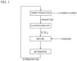
FIG. 1 ] It is a flowchart showing a process of a CO2 utilizing method in cement production exhaust gas according to one embodiment of the present invention. - [
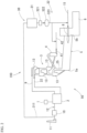
FIG. 2 ] It is a view simply showing the CO2 utilizing system in the cement production exhaust gas of the above-described embodiment. - [
FIG. 3 ] It is a block diagram showing a schematic composition of a methanation device configuring the CO2 separation and recover device in the cement production exhaust gas of the above-described embodiment. - An embodiment of a CO2 separation and recover method in cement production exhaust gas and a CO2 separation and recover device in cement production exhaust gas of the present invention will be explained below referring drawings.
- This embodiment is an example of removing an acidic component and a harmful component appropriately from CO2 in the cement production exhaust gas, then generating methane to utilize the methane as a part of fossil fuel or an entire alternative fuel to the cement production facility.
- A CO2 utilizing system 100 is provided with a
cement production facility 50 and an exhaustgas treatment facility 30 used by connected to thecement production facility 50 as shown inFIG. 2 . In this embodiment, the exhaustgas treatment facility 30 adds hydrogen to CO2 to the exhaust gas from thecement production facility 50 or CO2 that is separated and recovered from the exhaust gas to generate methane, and supplies the generated methane as an alternative fuel to a part or entire of the fossil fuel to thecement production facility 50. - The
cement production facility 50 is provided with, as the whole is shown inFIG. 2 , a raw material storehouse 1 individually storing lime stone, clay, silica stone, iron material and the like as cement materials, a material mill and a dryer (hereinafter "material mill/dryer") 2 milling and drying these cement materials, apreheater 3 preheating the powdery cement materials supplied via amaterial supply pipe 22 and obtained by the material mill, a calcination furnace 4 calcining the cement materials preheated by thepreheater 3, acement burning kiln 5 burning the cement materials that are calcined, and acooler 6 and the like to cool cement clinker after burned in thecement burning kiln 5. - The
cement burning kiln 5 is a lateral cylindrical rotary kiln which is slightly inclined, rotated around an axis to send the cement materials supplied in akiln tail part 5a from thepreheater 3 to a kilnfront part 5b, and heats and burns to generate cement clinker at about 1450°C by aburner 8 at the kilnfront part 5b while sending. The generated cement clinker is sent out from the kilnfront part 5b to the cooler 6. To theburner 8, afuel supply line 15 supplying fuel containing fossil fuel such as coal, petroleum and the like is connected. Other than thefuel supply line 15, in order to enlarge the heat energy, a supplying system (not illustrated) of an alternative heat source such as waste plastic, waste tires and the like is also provided. The cement clinker is cooled in thecooler 6 to a prescribed temperature, then sent to a finishing step. - The
preheater 3 is configured so that a plurality (four in an example shown inFIG. 2 ) ofcyclones 13 that flow the exhaust gas occurs in thecement burning kiln 5 are vertically connected as shown inFIG. 2 . Between thelowermost cyclone 13 and thenext cyclone 13, the calcination furnace 4 is connected. The cement material calcined by the combustion gas of the calcination furnace 4 is supplied to thekiln tail part 5a of thecement burning kiln 5 from thelowermost cyclone 13. - The calcination furnace 4 has a
burner 41 therein, and burns fuel such as coal or the like supplied from afuel supply line 42, thereby calcining the cement material sent from theupper cyclone 13, and supplying the calcined cement material to thelowermost cyclone 13 through ariser duct 25 together with the exhaust gas generated by the calcination. The cement material is supplied from thelowermost cyclone 13 to thekiln tail part 5a of thecement burning kiln 5. Theriser duct 25 sends the exhaust gas from thekiln tail part 5a of thecement burning kiln 5 to thelowermost cyclone 13, and the exhaust gas occurs in the calcination furnace 4 is also supplied to thecyclone 13 through theriser duct 25. Therefore, the exhaust gas of thecement burning kiln 5 and the exhaust gas from the calcination furnace 4 go together thorough thepreheater 3 from the lower side to the upper side and then are introduced into the material mill/dryer 2 passing through anexhaust pipe 9. - The material mill/
dryer 2 carries out pulverization and drying of the cement material simultaneously by introducing the exhaust gas from the calcination furnace 4 and thecement burning kiln 5. To the material mill/dryer 2, an exhaustgas treatment line 12 having adust collector 10, a chimney 11 and the like is connected. - The exhaust
gas treatment facility 30 is provided with an exhaustgas collection line 311 collecting the exhaust gas occurred in thecement burning kiln 5 and the calcination furnace 4 before discharged from the chimney 11 amethanation device 31 separating and recovering CO2 from the exhaust gas sent from the exhaustgas collection line 311 and adding hydrogen to the separated and recovered CO2 to generate methane, and amethane supply device 32 supplying the generated methane to thecement production facility 50. - The exhaust
gas collection line 311 is connected between thedust collector 10 and the chimney 11 in the exhaustgas treatment line 12 of thecement production facility 50, and collects a part of the exhaust gas generated during cement burning. Since it is the exhaust gas is generated by burning of cement, an exhaust gas due to combustion of fuel such as coal is partially included, but it contains a large amount of exhaust gas originated from lime stone. - The
methanation device 31 is provided with a CO2 separation/recoverdevice 310 that separates and recovers CO2 from the exhaust gas, ahydrogen mixing unit 316 that supplies and mixes hydrogen to CO2 separated and recovered by the CO2 separation/recoverdevice 310 and amethane production part 317 that generates methane from CO2 in which hydrogen is mixed. - As shown in
FIG. 3 , the CO2 separation/recoverdevice 310 is provided with, a harmfulcomponent removal unit 312 that removes harmful components such as SOx, NOx and the like from the exhaust gas collected in the exhaustgas collection line 311, a CO2 separation/recoverunit 313 that separates and recovers CO2 from the exhaust gas from which the harmful components are removed, acompression unit 314 that compresses the recovered CO2, and adehumidification unit 315 that removes moisture from the compressed CO2. - Since the exhaust gas sent from the exhaust
gas collection line 311 is combustion exhaust gas of fossil fuel such as coal, petroleum coke, heavy oil or the like, waste plastic, waste tires and the like, CO2 is contained at about 20% or more for example, and the other gas than CO2, an acidic component, and a harmful component are contained. Therefore, the harmfulcomponent removal unit 312 removes the acidic component (for example, acidification gas such as nitrogen oxides [NOx] or sulfur oxides [SOx]) and the harmful component (H2O, dusts and the like) from the exhaust gas, and is provided with a scrubber that is filled with an aqueous NaOH and the like, a dehumidifier, an electrostatic precipitator, and the like. By removing the acidic component and the harmful component, halogen is also removed with NOx, an absorption material (CO2 absorption material) of amine compound used for the next separation and recover of CO2 is prevented from deteriorating, and the deterioration of the absorbing ability is suppressed. - As a method of desulfurization (SOx removal method), a wet lime-gypsum method, magnesium hydroxide method, and a soda absorption method are known. These are methods of absorbing SOx in alkaline solution; and there is a coalash utilizing method as a dry method. As methods of treating desulfurization (removal of SOx) and denitration (removal of NOx) simultaneously, there are an activated carbon method that is a dry method, and an electron beam method. As the denitration method, there are a catalytic reduction method (SCR method) and a non-catalytic reduction process as dry methods; and an oxidation absorbing method, an oxidation reduction method, and an equimolar absorption method as wet methods.
- Since a suspension preheater unit works as a desulfurizing unit, in the exhaust gas from the cement production facility, there are many cases in which SOX is several-ten ppm, generally.
- Here, it seems that by an influence of impurities on the absorption material for CO2 separation and recover, affinity between amine compound and impurity compound does not largely differ in either a chemical absorption method and a physical absorption method. In recover of CO2 by the CO2 separation/recover
unit 313, SOx in the exhaust gas is combined with the amine compound in the absorption material and impedes the CO2 absorbing ability of the amine compound, so that the absorption rate is largely decreased as time passes. As described above, the amine compound has strong basicity, and other than SOx, NOx and halogen such as Cl, F and the like tend to be absorbed by the CO2 absorption material. - A Ni catalyst which is broadly used as a catalyst for methanation deteriorates a yield of the methanation under the sulfur compound mixed in H2 since the sulfur compound reacts on a surface of the Ni catalyst and covers the surface, so that it is necessary to be removed in the harmful
component removal unit 312. Similarly, NOx and halogen such as Cl, F and the like may be adhered to the surface of the Ni catalyst and deteriorate the yield of the methanation, so that it is necessary to be removed in the harmfulcomponent removal unit 312. - In the present embodiment, any of the above-described methods may be used for desulfurization (removal of SOx) and denitration (removal of NOx). For example, in the present embodiment, any of the above-described desulfurization methods and any of the above-described denitration methods are used to remove the acidification gas such as the nitrogen oxides (NOx), the sulfur oxides (SOx), and the like.
- The CO2 separation/recover
unit 313 is made of a standard CO2 recover device, and is provided with a CO2 absorption material (a liquid absorption material in which an amine compound is dissolved in water, a solid absorption material in which an amine compound is supported on a porous material, and the like) that absorbs CO2 in the exhaust gas when the exhaust gas in which the harmful matters are removed comes into contact therewith. Then, by heating the CO2 absorption material that has absorbed CO2 and the like, CO2 is taken out from the CO2 absorption material and recovered. The CO2 separation/recoverunit 313 discharges the exhaust gas after removing CO2 to the exterior. Thecompression unit 314 compresses the recovered CO2 by applying a pressure of 0.1 MPa or more, preferably 0.5 to 1.0 MPa. Thedehumidification unit 315 removes moisture contained in CO2 by cooling the compressed CO2. This dehumidification is carried out in order to remove moisture before methanation since the moisture affects the oxidation of a Ni-based catalyst in the methanation device. - The
hydrogen mixing unit 316 supplies hydrogen (for example, hydrogen gas) to the dehumidified CO2, mixes, and compresses it. The hydrogen produced by artificial light synthesis using renewable energy, decomposition of water, or the like can be utilized. The amount of hydrogen added by thehydrogen mixing unit 316 is appropriately set so that methane can be easily produced from CO2 in which hydrogen is mixed. - The
methane production unit 317 generates methane from CO2 in which hydrogen is mixed. Themethane production unit 317 is composed of a general methane production apparatus, provided with a plurality of reactors (not illustrated) filled with a catalyst exhibiting activity in methanation, and produces methane by supplying and reacting CO2 in which hydrogen is mixed with these reactors. For example, Ni, Pt, Pd, and Cu are used as a hydrogenation catalyst; in the methanation catalyst, particularly, Ni and Ni alloy on which Al2O3, Cr2O3, SiO2, MgAl2O4, TiO2, ZrO2 or the like are supported. - Conditions for a general methanation reaction (CO2 + 4H2 → 2H2O) have a temperature of 200°C to 700°C, preferably 200°C to 350°C, and a pressure of 0.1 to 3 MPa, and it is reacted in multiple stage in order to improve the reaction yield of methane.
- As shown in
FIG. 2 , themethane supply device 32 is provided with atank 322 compressing methane produced by themethanation device 31 by apump 321 and storing it, and amethane supply line 323 that is connected to thetank 322 and sends methane to theburner 8 of the kilnfront part 5b and theburner 41 of the calcination furnace 4 respectively. Themethane supply line 321 is connected to thefuel supply line 15 supplying fuel such as coal, petroleum or the like to theburner 8 of thecement burning kiln 5, and thefuel supply line 42 supplying fuel such as coal or the like to theburner 41 of the calcination furnace 4. As a result, methane is supplied to theburners - A method of reducing CO2 in the exhaust gas of the
cement production facility 50 and effectively utilizing it using the above-described CO2 utilizing system will be explained with the flowchart shown inFIG. 1 . - In the
cement production facility 50, the powdery cement material obtained by milling and drying lime stone, clay, silica stone, iron material and the like as the cement material is preheated; the preheated cement material is subjected to the calcination and then burned, and cooled, so that the cement clinker is produced. The exhaust gas occurred in thecement burning kiln 5 and the calcination furnace 4 during the production of the cement clinker goes through thepreheater 3 from the lower side to the upper side, passes through theexhaust pipe 9 to be introduced into the material mill/drier 2 for drying the cement material, then is discharged from the chimney 11 via thedust collector 10. - In this process of producing cement, a part of the exhaust gas occurred when the cement is burned is collected to the exhaust
gas collection line 311 of themethanation device 31 between thedust collector 10 and the chimney 11 of the exhaustgas treatment line 12. Next, the harmfulcomponent removal unit 312 removes the acidic component and the harmful component from the exhaust gas (harmful component removal step). In the harmfulcomponent removal unit 312, nitrogen oxides (NOx), sulfur oxides (SOx), halogen, H2O, dusts and the like are removed. Then, CO2 is taken out from the exhaust gas by the CO2 separation/recoverunit 313 and separated/recovered. At this time, the exhaust gas from which CO2 is removed is discharged outside. - Next, the
compression unit 314 compresses the recovered CO2 to be 0.1 MPa or more by applying a pressure of 0.5 to 1.0 MPa, and then moisture included in CO2 is removed by thedehumidification unit 315. Then, by thehydrogen mixing unit 316, hydrogen is supplied to the dehumidified CO2 and mixed with it, then pressurized. Then, by themethane production unit 317, methane is generated from CO2 in which hydrogen is mixed. - The methane generated in this manner is stored in the
tank 322 of themethane supply device 32. The methane stored in thetank 322 is supplied to thecement burning kiln 5 and the calcination furnace 4 via themethane supply line 323. In thecement burning kiln 5, fossil fuel such as petroleum, coal of the like is supplied from thefuel supply line 15, however, some of the fossil fuel can be substituted with methane by supplying methane, and the fossil fuel can be reduced. Similarly, in the calcination furnace 4, some of the fuel such as coal is substituted with methane, so that fossil fuel can be reduced. - In the present embodiment, before separation and recover of the exhaust gas from the
cement production facility 50, by removing the acidic components such as SOX, NOX, halogen and the like, and the harmful components such as H2O, dusts and the like contained in CO2 of the cement production exhaust gas, the deterioration of the absorption ability of the CO2 absorption material can be suppressed. Accordingly, CO2 can be efficiently recovered from the cement production exhaust gas. The CO2 absorption material also can be maintained to have stable performance for a long time. By converting CO2 appropriately treated to methane, CO2 discharged from thecement production facility 50 can be reduced; and by using the methane as the alternative fuel for thecement burning kiln 5 and the calcination furnace 4, the methane can be effectively utilized. Notably, since methane substitutes for the fossil fuel such as coal and petroleum being the major cause of the global warming, the usage of the fossil fuel is decreased to reduce CO2 derived from energy, and the reduction effect of the greenhouse gas can be improved. - The present invention is not limited to the above-described embodiments and various modifications may be made without departing from the scope of the present invention.
- For example, although the generated methane is supplied to both the
cement burning kiln 5 and the calcination furnace 4, it is possible to supply to either one of them. - Moreover, although the methane is generated using the exhaust gas from both the
cement burning kiln 5 and the calcination furnace 4, it is possible to apply to a cement production facility having no calcination furnace; in this case, methane is generated from exhaust gas from a cement burning kiln. - Acidic components and harmful components is appropriately removed from CO2 in exhaust gas of a cement production facility and deterioration of absorption ability of a CO2 absorption material can be suppressed.
-
- 1
- Raw material storehouse
- 2
- Material mill/dryer
- 3
- Preheater
- 4
- Calcination furnace
- 5
- Cement burning kiln
- 5a
- Kiln tail part
- 5b
- Kiln front part
- 6
- Cooler
- 8
- Burner
- 9
- Exhaust pipe
- 10
- Dust collector
- 11
- Chimney
- 12
- Exhaust gas treatment line
- 13
- Cyclone
- 15
- Fuel supply line
- 22
- Material supply pipe
- 25
- Riser duct
- 30
- Exhaust gas treatment facility
- 31
- Methanation device
- 310
- CO2 separation/recover device
- 311
- Exhaust gas collection line
- 312
- Harmful component removal device
- 313
- CO2 separation/recover unit
- 314
- Compression unit
- 315
- Dehumidification unit
- 316
- Hydrogen mixing unit
- 317
- Methane production unit
- 32
- Methane supply device
- 321
- Pump
- 322
- Tank
- 323
- Methane supply line
- 41
- Burner
- 42
- Fuel supply line
- 50
- Cement production facility
- 100
- CO2 utilizing system
Claims (2)
- A CO2 separation and recover method in cement production exhaust gas, comprisinga step of harmful component removal that removes an acidic component and a harmful component from exhaust gas discharged from a cement production facility; anda step of CO2 separation and recover that separates and recovers CO2 by bringing the exhaust gas from which the acidic component and the harmful component are removed into contact with a CO2 absorption material.
- A CO2 separation and recover device in cement production exhaust gas, comprising a cement production facility that is provided witha harmful component removal unit that removes an acidic component and a harmful component from exhaust gas from the cement production facility, anda CO2 separation and recover unit that separates and recovers CO2 by bringing the exhaust from which the acidic component and the harmful component are removed into contact with a CO2 absorption material.
Applications Claiming Priority (4)
| Application Number | Priority Date | Filing Date | Title |
|---|---|---|---|
| JP2020097644A JP7215462B2 (en) | 2020-06-04 | 2020-06-04 | CO2 Utilization Method and CO2 Utilization System in Exhaust Gas from Cement Manufacturing |
| JP2020097645A JP2021187721A (en) | 2020-06-04 | 2020-06-04 | Utilization method of co2 in cement manufacture exhaust gas and co2 utilization system |
| JP2020101457A JP7230884B2 (en) | 2020-06-11 | 2020-06-11 | CO2 Utilization Method and CO2 Utilization System in Exhaust Gas from Cement Manufacturing |
| PCT/JP2021/020405 WO2021246317A1 (en) | 2020-06-04 | 2021-05-28 | Method for separating and recovering co2 in cement production exhaust gas, and co2 separation and recovery device |
Publications (1)
| Publication Number | Publication Date |
|---|---|
| EP4163266A1 true EP4163266A1 (en) | 2023-04-12 |
Family
ID=78830422
Family Applications (1)
| Application Number | Title | Priority Date | Filing Date |
|---|---|---|---|
| EP21818173.3A Withdrawn EP4163266A1 (en) | 2020-06-04 | 2021-05-28 | Method for separating and recovering co2 in cement production exhaust gas, and co2 separation and recovery device |
Country Status (4)
| Country | Link |
|---|---|
| US (1) | US20230233987A1 (en) |
| EP (1) | EP4163266A1 (en) |
| CN (1) | CN115697904A (en) |
| WO (1) | WO2021246317A1 (en) |
Families Citing this family (4)
| Publication number | Priority date | Publication date | Assignee | Title |
|---|---|---|---|---|
| KR102724049B1 (en) * | 2022-01-21 | 2024-10-31 | (주)로우카본 | Carbon dioxide capture and carbon resource conversion system for cement production plant |
| EP4238947B1 (en) * | 2022-03-01 | 2024-06-05 | Südbayerisches Portland-Zementwerk Gebr. Wiesböck & Co. GmbH | Method and plant for treating raw-meal in a cement clinker manufacturing process |
| CA3268118A1 (en) | 2022-03-01 | 2023-09-07 | Südbayerisches Portland-Zementwerk Gebr. Wiesböck & Co. GmbH | Method and plant for treating raw-meal in a cement clinker manufacturing process |
| KR102754863B1 (en) * | 2022-04-27 | 2025-01-15 | (주)로우카본 | Carbon dioxide capture and carbon resource conversion, and hydrogen production system for cement production plant |
Family Cites Families (14)
| Publication number | Priority date | Publication date | Assignee | Title |
|---|---|---|---|---|
| JPH10185170A (en) * | 1996-12-25 | 1998-07-14 | Ebara Corp | Combustion apparatus |
| US8182771B2 (en) * | 2009-04-22 | 2012-05-22 | General Electric Company | Method and apparatus for substitute natural gas generation |
| CN103221114A (en) * | 2010-09-02 | 2013-07-24 | 加州大学评议会 | Method and system for capturing carbon dioxide and/or sulfur dioxide from a gas stream |
| JP2015030653A (en) * | 2013-08-06 | 2015-02-16 | 千代田化工建設株式会社 | Energy utilization system, and energy utilization method |
| WO2015055349A1 (en) * | 2013-10-16 | 2015-04-23 | Paul Scherrer Institut | Integrated process/plant for storage of co2 by conversion to synthetic natural gas |
| CN106996701A (en) * | 2016-08-05 | 2017-08-01 | 太平洋工程株式会社 | The method of operation of cement kiln |
| JP2018052746A (en) * | 2016-09-26 | 2018-04-05 | 太平洋セメント株式会社 | Cement firing apparatus and method for cement clinker burning |
| FR3059315B1 (en) * | 2016-11-29 | 2018-11-16 | IFP Energies Nouvelles | PROCESS FOR PRODUCING SYNTHESIS GAS FROM LIGHT HYDROCARBON STREAM AND COMBUSTION FUMES FROM CEMENT CLINKER MANUFACTURING UNIT. |
| CN107824026A (en) * | 2017-11-15 | 2018-03-23 | 安徽海螺建材设计研究院 | A kind of cement kiln flue gas collecting carbonic anhydride treater |
| JP6956665B2 (en) | 2018-03-27 | 2021-11-02 | 大阪瓦斯株式会社 | Method of methaneization of carbon dioxide in combustion exhaust gas and methane production equipment |
| JP7144306B2 (en) | 2018-12-17 | 2022-09-29 | 株式会社パイロットコーポレーション | Ink composition for oil-based ballpoint pen and oil-based ballpoint pen using the same |
| JP6838599B2 (en) | 2018-12-17 | 2021-03-03 | 横浜ゴム株式会社 | Pneumatic tires |
| JP2020101457A (en) | 2018-12-21 | 2020-07-02 | 中国電力株式会社 | Cable measurement apparatus and cable measurement system |
| CN110455091A (en) * | 2019-09-16 | 2019-11-15 | 中国科学院过程工程研究所 | A SCR denitrification system for cement flue gas |
-
2021
- 2021-05-28 WO PCT/JP2021/020405 patent/WO2021246317A1/en not_active Ceased
- 2021-05-28 EP EP21818173.3A patent/EP4163266A1/en not_active Withdrawn
- 2021-05-28 CN CN202180040170.0A patent/CN115697904A/en active Pending
- 2021-05-28 US US17/928,716 patent/US20230233987A1/en active Pending
Also Published As
| Publication number | Publication date |
|---|---|
| US20230233987A1 (en) | 2023-07-27 |
| CN115697904A (en) | 2023-02-03 |
| WO2021246317A1 (en) | 2021-12-09 |
Similar Documents
| Publication | Publication Date | Title |
|---|---|---|
| US20230233987A1 (en) | Co2 separation and recovery method and co2 separation and recovery device in cement production exhaust gas | |
| KR20220005074A (en) | Systems and methods for carbon capture | |
| Manovic et al. | CaO-based pellets supported by calcium aluminate cements for high-temperature CO2 capture | |
| CN109482049B (en) | Dry desulfurization, denitrification and purification integrated process for coke oven flue gas | |
| JP2006524790A (en) | In situ capture of carbon dioxide and sulfur dioxide in a fluidized bed combustor. | |
| KR102556853B1 (en) | Carbon Dioxide Removing System From Exhaust Gases | |
| JP7374856B2 (en) | Cement manufacturing method and cement manufacturing system | |
| JP7600011B2 (en) | CEMENT CLINKER PRODUCTION SYSTEM AND CEMENT CLINKER PRODUCTION METHOD | |
| WO2021246318A1 (en) | Method for producing methane from co2 in cement production exhaust gas, and methanation apparatus | |
| JP7230884B2 (en) | CO2 Utilization Method and CO2 Utilization System in Exhaust Gas from Cement Manufacturing | |
| JP4775858B2 (en) | Method for regenerating copper-based absorbent and method for removing mercury from source gas | |
| EP3019268B1 (en) | Method for ventilation air methane mitigation | |
| JP2023016868A (en) | Utilization method of co2 in cement manufacture exhaust gas and co2 utilization system | |
| JP7230885B2 (en) | CO2 Utilization Method and CO2 Utilization System in Exhaust Gas from Cement Manufacturing | |
| EP4166527A1 (en) | Method for activating co2 in exhaust gas from cement production, and co2 activation system | |
| JP2021191731A (en) | Method for utilizing co2 in cement production exhaust gas, and co2 utilization system | |
| JP7215462B2 (en) | CO2 Utilization Method and CO2 Utilization System in Exhaust Gas from Cement Manufacturing | |
| JP7555867B2 (en) | CEMENT CLINKER PRODUCTION SYSTEM AND CEMENT CLINKER PRODUCTION METHOD | |
| WO2021246319A1 (en) | Cement production method and cement production system | |
| WO2021246315A1 (en) | Method and system for utilizing co2 in cement production exhaust gas | |
| JP2010215802A (en) | Dry gas purification facility and coal gasification combined power generation facility | |
| JP2021191732A (en) | Method of producing valuables from exhaust from cement production | |
| JP2024139977A (en) | CEMENT CLINKER PRODUCTION SYSTEM AND CEMENT CLINKER PRODUCTION METHOD | |
| JP2026059064A (en) | Cement clinker manufacturing system and cement clinker manufacturing method | |
| JP2022096846A (en) | Cement clinker manufacturing system |
Legal Events
| Date | Code | Title | Description |
|---|---|---|---|
| STAA | Information on the status of an ep patent application or granted ep patent |
Free format text: STATUS: THE INTERNATIONAL PUBLICATION HAS BEEN MADE |
|
| PUAI | Public reference made under article 153(3) epc to a published international application that has entered the european phase |
Free format text: ORIGINAL CODE: 0009012 |
|
| STAA | Information on the status of an ep patent application or granted ep patent |
Free format text: STATUS: REQUEST FOR EXAMINATION WAS MADE |
|
| 17P | Request for examination filed |
Effective date: 20230102 |
|
| AK | Designated contracting states |
Kind code of ref document: A1 Designated state(s): AL AT BE BG CH CY CZ DE DK EE ES FI FR GB GR HR HU IE IS IT LI LT LU LV MC MK MT NL NO PL PT RO RS SE SI SK SM TR |
|
| DAV | Request for validation of the european patent (deleted) | ||
| DAX | Request for extension of the european patent (deleted) | ||
| STAA | Information on the status of an ep patent application or granted ep patent |
Free format text: STATUS: THE APPLICATION HAS BEEN WITHDRAWN |
|
| 18W | Application withdrawn |
Effective date: 20240604 |