EP4163168A1 - Electric parking brake control device and electric parking brake control method - Google Patents
Electric parking brake control device and electric parking brake control method Download PDFInfo
- Publication number
- EP4163168A1 EP4163168A1 EP21816797.1A EP21816797A EP4163168A1 EP 4163168 A1 EP4163168 A1 EP 4163168A1 EP 21816797 A EP21816797 A EP 21816797A EP 4163168 A1 EP4163168 A1 EP 4163168A1
- Authority
- EP
- European Patent Office
- Prior art keywords
- current
- voltage
- motor
- variation
- electric
- Prior art date
- Legal status (The legal status is an assumption and is not a legal conclusion. Google has not performed a legal analysis and makes no representation as to the accuracy of the status listed.)
- Granted
Links
Images


Classifications
-
- B—PERFORMING OPERATIONS; TRANSPORTING
- B60—VEHICLES IN GENERAL
- B60T—VEHICLE BRAKE CONTROL SYSTEMS OR PARTS THEREOF; BRAKE CONTROL SYSTEMS OR PARTS THEREOF, IN GENERAL; ARRANGEMENT OF BRAKING ELEMENTS ON VEHICLES IN GENERAL; PORTABLE DEVICES FOR PREVENTING UNWANTED MOVEMENT OF VEHICLES; VEHICLE MODIFICATIONS TO FACILITATE COOLING OF BRAKES
- B60T13/00—Transmitting braking action from initiating means to ultimate brake actuator with power assistance or drive; Brake systems incorporating such transmitting means, e.g. air-pressure brake systems
- B60T13/74—Transmitting braking action from initiating means to ultimate brake actuator with power assistance or drive; Brake systems incorporating such transmitting means, e.g. air-pressure brake systems with electrical assistance or drive
-
- H—ELECTRICITY
- H02—GENERATION; CONVERSION OR DISTRIBUTION OF ELECTRIC POWER
- H02P—CONTROL OR REGULATION OF ELECTRIC MOTORS, ELECTRIC GENERATORS OR DYNAMO-ELECTRIC CONVERTERS; CONTROLLING TRANSFORMERS, REACTORS OR CHOKE COILS
- H02P3/00—Arrangements for stopping or slowing electric motors, generators, or dynamo-electric converters
- H02P3/02—Details of stopping control
- H02P3/04—Means for stopping or slowing by a separate brake, e.g. friction brake or eddy-current brake
-
- B—PERFORMING OPERATIONS; TRANSPORTING
- B60—VEHICLES IN GENERAL
- B60T—VEHICLE BRAKE CONTROL SYSTEMS OR PARTS THEREOF; BRAKE CONTROL SYSTEMS OR PARTS THEREOF, IN GENERAL; ARRANGEMENT OF BRAKING ELEMENTS ON VEHICLES IN GENERAL; PORTABLE DEVICES FOR PREVENTING UNWANTED MOVEMENT OF VEHICLES; VEHICLE MODIFICATIONS TO FACILITATE COOLING OF BRAKES
- B60T13/00—Transmitting braking action from initiating means to ultimate brake actuator with power assistance or drive; Brake systems incorporating such transmitting means, e.g. air-pressure brake systems
- B60T13/10—Transmitting braking action from initiating means to ultimate brake actuator with power assistance or drive; Brake systems incorporating such transmitting means, e.g. air-pressure brake systems with fluid assistance, drive, or release
- B60T13/66—Electrical control in fluid-pressure brake systems
- B60T13/662—Electrical control in fluid-pressure brake systems characterised by specified functions of the control system components
-
- B—PERFORMING OPERATIONS; TRANSPORTING
- B60—VEHICLES IN GENERAL
- B60T—VEHICLE BRAKE CONTROL SYSTEMS OR PARTS THEREOF; BRAKE CONTROL SYSTEMS OR PARTS THEREOF, IN GENERAL; ARRANGEMENT OF BRAKING ELEMENTS ON VEHICLES IN GENERAL; PORTABLE DEVICES FOR PREVENTING UNWANTED MOVEMENT OF VEHICLES; VEHICLE MODIFICATIONS TO FACILITATE COOLING OF BRAKES
- B60T13/00—Transmitting braking action from initiating means to ultimate brake actuator with power assistance or drive; Brake systems incorporating such transmitting means, e.g. air-pressure brake systems
- B60T13/74—Transmitting braking action from initiating means to ultimate brake actuator with power assistance or drive; Brake systems incorporating such transmitting means, e.g. air-pressure brake systems with electrical assistance or drive
- B60T13/741—Transmitting braking action from initiating means to ultimate brake actuator with power assistance or drive; Brake systems incorporating such transmitting means, e.g. air-pressure brake systems with electrical assistance or drive acting on an ultimate actuator
-
- B—PERFORMING OPERATIONS; TRANSPORTING
- B60—VEHICLES IN GENERAL
- B60T—VEHICLE BRAKE CONTROL SYSTEMS OR PARTS THEREOF; BRAKE CONTROL SYSTEMS OR PARTS THEREOF, IN GENERAL; ARRANGEMENT OF BRAKING ELEMENTS ON VEHICLES IN GENERAL; PORTABLE DEVICES FOR PREVENTING UNWANTED MOVEMENT OF VEHICLES; VEHICLE MODIFICATIONS TO FACILITATE COOLING OF BRAKES
- B60T17/00—Component parts, details, or accessories of power brake systems not covered by groups B60T8/00, B60T13/00 or B60T15/00, or presenting other characteristic features
- B60T17/18—Safety devices; Monitoring
- B60T17/22—Devices for monitoring or checking brake systems; Signal devices
-
- B—PERFORMING OPERATIONS; TRANSPORTING
- B60—VEHICLES IN GENERAL
- B60T—VEHICLE BRAKE CONTROL SYSTEMS OR PARTS THEREOF; BRAKE CONTROL SYSTEMS OR PARTS THEREOF, IN GENERAL; ARRANGEMENT OF BRAKING ELEMENTS ON VEHICLES IN GENERAL; PORTABLE DEVICES FOR PREVENTING UNWANTED MOVEMENT OF VEHICLES; VEHICLE MODIFICATIONS TO FACILITATE COOLING OF BRAKES
- B60T7/00—Brake-action initiating means
- B60T7/02—Brake-action initiating means for personal initiation
- B60T7/08—Brake-action initiating means for personal initiation hand actuated
- B60T7/10—Disposition of hand control
- B60T7/107—Disposition of hand control with electrical power assistance
-
- F—MECHANICAL ENGINEERING; LIGHTING; HEATING; WEAPONS; BLASTING
- F16—ENGINEERING ELEMENTS AND UNITS; GENERAL MEASURES FOR PRODUCING AND MAINTAINING EFFECTIVE FUNCTIONING OF MACHINES OR INSTALLATIONS; THERMAL INSULATION IN GENERAL
- F16D—COUPLINGS FOR TRANSMITTING ROTATION; CLUTCHES; BRAKES
- F16D55/00—Brakes with substantially-radial braking surfaces pressed together in axial direction, e.g. disc brakes
- F16D55/02—Brakes with substantially-radial braking surfaces pressed together in axial direction, e.g. disc brakes with axially-movable discs or pads pressed against axially-located rotating members
- F16D55/22—Brakes with substantially-radial braking surfaces pressed together in axial direction, e.g. disc brakes with axially-movable discs or pads pressed against axially-located rotating members by clamping an axially-located rotating disc between movable braking members, e.g. movable brake discs or brake pads
- F16D55/224—Brakes with substantially-radial braking surfaces pressed together in axial direction, e.g. disc brakes with axially-movable discs or pads pressed against axially-located rotating members by clamping an axially-located rotating disc between movable braking members, e.g. movable brake discs or brake pads with a common actuating member for the braking members
- F16D55/225—Brakes with substantially-radial braking surfaces pressed together in axial direction, e.g. disc brakes with axially-movable discs or pads pressed against axially-located rotating members by clamping an axially-located rotating disc between movable braking members, e.g. movable brake discs or brake pads with a common actuating member for the braking members the braking members being brake pads
- F16D55/226—Brakes with substantially-radial braking surfaces pressed together in axial direction, e.g. disc brakes with axially-movable discs or pads pressed against axially-located rotating members by clamping an axially-located rotating disc between movable braking members, e.g. movable brake discs or brake pads with a common actuating member for the braking members the braking members being brake pads in which the common actuating member is moved axially, e.g. floating caliper disc brakes
-
- F—MECHANICAL ENGINEERING; LIGHTING; HEATING; WEAPONS; BLASTING
- F16—ENGINEERING ELEMENTS AND UNITS; GENERAL MEASURES FOR PRODUCING AND MAINTAINING EFFECTIVE FUNCTIONING OF MACHINES OR INSTALLATIONS; THERMAL INSULATION IN GENERAL
- F16D—COUPLINGS FOR TRANSMITTING ROTATION; CLUTCHES; BRAKES
- F16D65/00—Parts or details
- F16D65/14—Actuating mechanisms for brakes; Means for initiating operation at a predetermined position
- F16D65/16—Actuating mechanisms for brakes; Means for initiating operation at a predetermined position arranged in or on the brake
- F16D65/18—Actuating mechanisms for brakes; Means for initiating operation at a predetermined position arranged in or on the brake adapted for drawing members together, e.g. for disc brakes
- F16D65/183—Actuating mechanisms for brakes; Means for initiating operation at a predetermined position arranged in or on the brake adapted for drawing members together, e.g. for disc brakes with force-transmitting members arranged side by side acting on a spot type force-applying member
-
- H—ELECTRICITY
- H02—GENERATION; CONVERSION OR DISTRIBUTION OF ELECTRIC POWER
- H02P—CONTROL OR REGULATION OF ELECTRIC MOTORS, ELECTRIC GENERATORS OR DYNAMO-ELECTRIC CONVERTERS; CONTROLLING TRANSFORMERS, REACTORS OR CHOKE COILS
- H02P29/00—Arrangements for regulating or controlling electric motors, appropriate for both AC and DC motors
- H02P29/02—Providing protection against overload without automatic interruption of supply
- H02P29/032—Preventing damage to the motor, e.g. setting individual current limits for different drive conditions
-
- H—ELECTRICITY
- H02—GENERATION; CONVERSION OR DISTRIBUTION OF ELECTRIC POWER
- H02P—CONTROL OR REGULATION OF ELECTRIC MOTORS, ELECTRIC GENERATORS OR DYNAMO-ELECTRIC CONVERTERS; CONTROLLING TRANSFORMERS, REACTORS OR CHOKE COILS
- H02P29/00—Arrangements for regulating or controlling electric motors, appropriate for both AC and DC motors
- H02P29/40—Regulating or controlling the amount of current drawn or delivered by the motor for controlling the mechanical load
-
- F—MECHANICAL ENGINEERING; LIGHTING; HEATING; WEAPONS; BLASTING
- F16—ENGINEERING ELEMENTS AND UNITS; GENERAL MEASURES FOR PRODUCING AND MAINTAINING EFFECTIVE FUNCTIONING OF MACHINES OR INSTALLATIONS; THERMAL INSULATION IN GENERAL
- F16D—COUPLINGS FOR TRANSMITTING ROTATION; CLUTCHES; BRAKES
- F16D2121/00—Type of actuator operation force
- F16D2121/18—Electric or magnetic
- F16D2121/24—Electric or magnetic using motors
Definitions
- the present invention relates to an electric-parking-brake control device and an electric-parking-brake control method used for a vehicle such as an automobile.
- a brake apparatus is an electric brake that presses a pressing member, such as a brake shoe or a drum shoe, against a rotating member, such as a brake disc or a brake drum, by rotation of a motor to perform braking.
- a pressing member such as a brake shoe or a drum shoe
- a rotating member such as a brake disc or a brake drum
- a method including: determining a clamping force as a function of a motor constant of a brake motor; and calculating the motor constant from the most recent measured value of a motor current (10, IA) measured during the operation of the brake motor, in which an idling voltage (Us0) and an idling current (10) in the brake motor are measured during an idling phase, and the motor current (IA) is calculated during a dynamic current variation phase to determine the motor constant (KM)
- a method for controlling thrust by determining a current-cutting-off threshold using the motor constant computed here.
- An object of the present invention is to provide an electric-parking-brake control device and an electric-parking-brake control method capable of improving computation accuracy of pressing thrust regardless of an individual difference and a use situation of a brake apparatus, and the like.
- the present invention is an electric-parking-brake control device including a controller that controls thrust of a piston that presses a brake pad by driving of a motor on the basis of a current and a voltage
- the controller includes a motor stop current computation unit that computes a stop current of the motor, and the motor stop current computation unit: in a period of variation in the current and the voltage before an idling current period, computes, as a plurality of prospective values, a variation in the current and the voltage or a variation in a function including the current and the voltage in the idling current period; at a predetermined time during the current variation period, selects one of the plurality of prospective values on the basis of the current and the voltage; and on the basis of the variation in the current and the voltage or the function related to the selected prospective value, computes a characteristic parameter of the motor to compute a stop current of the motor.
- the present invention is an electric-parking-brake control method for controlling thrust of a piston that presses a brake pad by driving of a motor on the basis of a current and a voltage, the method including: in a period of variation in the current and the voltage before an idling current period, computing, as a plurality of prospective values, a variation in the current and the voltage or a variation in a function including the current and the voltage in the idling current period; at a predetermined time during the current variation period, selecting one of the plurality of prospective values on the basis of the current and the voltage; and on the basis of the variation in the current and the voltage or the function related to the selected prospective value, computing a characteristic parameter of the motor to compute a stop current of the motor.
- the present invention can provide an electric-parking-brake control device and an electric-parking-brake control method capable of improving computation accuracy of pressing thrust regardless of an individual difference and a use situation of a brake apparatus, and the like.
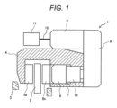
- FIG. 1 is a cross-sectional view illustrating a configuration of an electric parking brake apparatus according to an embodiment of the invention
- FIG. 2 is a diagram illustrating a configuration example of a vehicle including the electric parking brake apparatus in FIG. 1 .
- brake apparatuses to which the present embodiment is applied are disc brake apparatuses 1a and 1b (the configurations of 1a and 1b are the same), and are provided at left and right rear wheel portions of a vehicle 21.
- the disc brake apparatuses 1a and 1b obtain a braking force by pressing brake pads against discs 2a and 2b rotating together with the rear wheels.
- the vehicle 21 includes a brake pedal 22 operated by the driver, a master cylinder 23 that includes an internal piston moved by the operation of the brake pedal 22 to generate a pressure, pipes 24a, 24b, and 24c that transmit the pressure to left and right front wheels and rear wheels, and disc brake apparatuses 25a and 25b (the configurations of a and b are the same) of the front wheels.
- a hydraulic-pressure control apparatus 27 is disposed between the master cylinder 23 and the pipe 24 of each wheel to control the hydraulic pressure and perform a side-slip prevention apparatus, and the like.
- the disc brake apparatus 1 (since a and b have the same configuration, a and b are omitted below) arranged at the rear wheel includes a carrier 3 fixed to a non-rotating portion of the vehicle 21 located closer to the inside of the vehicle 21 than a disc rotor (rotating member) 2 is, a cylinder 4 supported floatably in an axial direction of the disc rotor 2, brake pads (pressing members) 5a and 5b disposed on both sides of the disc rotor 2, a piston 6 slidable in the cylinder 4, a pressure chamber 7, and a motor 8 for driving the piston 6.
- a carrier 3 fixed to a non-rotating portion of the vehicle 21 located closer to the inside of the vehicle 21 than a disc rotor (rotating member) 2 is, a cylinder 4 supported floatably in an axial direction of the disc rotor 2, brake pads (pressing members) 5a and 5b disposed on both sides of the disc rotor 2, a piston 6 slidable in the cylinder 4, a pressure chamber
- An output shaft of the motor 8 is connected to a reduction drive 9, an output shaft of the reduction drive 9 is connected to a rotation-to-linear-motion conversion mechanism 10, and the rotation-to-linear-motion conversion mechanism 10 can move the piston 6 in a linear-motion direction.
- the motor 8 is connected to a controller 11 by an electric wire 12.
- the pressure chamber 7 is connected to the pipe 24.
- the controller 11 controls the rotation of the motor 8.
- FIG. 3 is a block diagram illustrating a configuration of the controller 11.
- the controller 11 includes a current detection unit 31 that detects the current during driving of the motor 8, a motor stop current computation unit 32 that computes a stop current of the motor 8 from the current during driving of the motor 8 detected by the current detection unit 31, a timer 33 that measures the detection time of the current detection unit 31, and a driver circuit 34 that controls the motor 8 on the basis of a current value detected by the current detection unit 31 and a result computed by the motor stop current computation unit 32.
- the motor stop current computation unit 32 executes the computation on the basis of a control program stored in a storage unit (not illustrated).
- a parking brake switch 35 operated by the driver, various sensors 36 for acceleration, vehicle speed, and the like, a controller area network (CAN) 37 for acquiring information on each unit of the vehicle 21, and a power supply 38, so that the power supply to the motor 8 is controlled according to the respective signals. Furthermore, a notification means 39, such as a warning light, is connected to the controller 11 as necessary.
- the various sensors 36 include a power supply sensor that detects the power supply, and a voltage sensor that detects the voltage of the motor.
- the brake apparatus 1 When the driver operates the brake pedal 22, the master cylinder 23 generates a hydraulic pressure, and the hydraulic pressure communicates with the pressure chamber 7 through the pipe 24. Therefore, a force due to the pressure propels the piston 6 to generate a force that presses the brake pads 5a and 5b against the disc rotor 2 to generate a braking force.
- the brake apparatus to which the hydraulic-pressure control apparatus 27 and the like are added can generate a necessary hydraulic pressure with the hydraulic-pressure control apparatus 27 regardless of the operation of the brake pedal 22 by the driver, and similarly generates a braking force by the generated hydraulic pressure.
- a braking force is generated on the basis of the detection of a switching-on operation of the parking brake switch 35 by the driver, a vehicle state, or the like, and an applying command 41 from the controller 11 for thrust generation.
- the motor 8 is driven, and the driving force of the motor 8 generates thrust of the piston 6 via the reduction drive 9, the rotation-to-linear-motion conversion mechanism 10, and the like. This operation is illustrated in FIG. 4 .
- FIG. 4 is a cross-sectional view illustrating the electric parking brake apparatus at the time of clamping.
- the piston 6 comes into contact with the brake pad 5b, and a force is generated in the cylinder 4 in a direction in which the brake pad 5a is pressed against the disc rotor 2, so that the disc rotor 2 is sandwiched between the brake pads 5a and 5b to generate a braking force.
- the driving of the motor 8 is stopped.
- FIG. 5 is a flowchart illustrating operations of the controller 11.
- step S50 when the motor stop current computation unit 32 of the controller 11 determines that an applying command has been started (Yes in step S50), the motor 8 is driven (step S51). In a case where an applying command is not started (No in step S51), the determination of the start of an applying command is repeated.
- step S53 determines whether or not the current has reached the maximum value, and in a case where the current has reached the maximum value (Yes in step S52), a motor stop current computation (step S53) is performed.
- a specific parameter calculation step S54
- a motor stop current calculation step S55
- step S57 After the motor stop current calculation, in a case where a motor current 43 (current) exceeds a computed motor stop current 44 or if it is determined that a predetermined time has elapsed after the exceeding (Yes in step S56), the motor 8 stops (step S57).
- FIG. 6 illustrates time history waveforms of the applying command 41, a thrust 42, the motor current 43, and a voltage between the motor terminals during this time.
- the applying command 41 is input, the motor 8 is driven and the piston 6 is moved in a direction approaching the brake pad 5b. Then, the piston 6 idles until coming into contact with the brake pad 5b. At this time, the load applied to the motor 8 is small, and the motor current 43 maintains a substantially constant low value (idling current 45). After an inrush current flows immediately after the start of driving of the motor, the motor current 43 converges, and the current flowing from the convergence until the piston 6 comes into contact with the brake pad 5b is the idling current 45.
- a period before a predetermined time T0 is defined as a current variation period 47, and a period after the current variation period 47 is defined as an idling current period 48.
- the predetermined time T0 is a boundary point at which the motor current 43 becomes substantially constant from a state in which the motor current 43 varies.
- the thrust 42 of the piston 6 increases.
- the pressing force by which the brake pad 5b presses the disc rotor 2 also starts to increase, the load on the motor 8 gradually increases, and accordingly, the motor current 43 increases.
- the motor 8 is stopped.
- the motor since the current detected by the sensor is collected at every sampling time, the motor may be stopped when the detected currents exceed the motor stop current 44 a predetermined number of times (for example, three times).
- FIG. 7 is a flowchart illustrating a procedure of the motor stop current computation.
- Step S53 of the motor stop current computation includes step S54 that is a portion for computing, in a case where a motor current 43 is in the current variation period 47, characteristic parameters on the basis of the current and the voltage in the current variation period 47, and a motor stop current calculation step S55 for computing a motor stop current 44 from the obtained characteristic parameters.
- the characteristic parameters are parameters that vary characteristics of individual motors.
- step S54 of the characteristic parameter computation the current and the voltage, or a function including the current and the voltage is measured (step S58) . Then, the current and the voltage, or the function including the current and the voltage during the idling current period 48 is assumed as a plurality of prospective values (c1 to cn) (step S59), and an approximate expression (step S60) for reproducing a measured value is obtained using each prospective value.
- the plurality of assumed prospective values (c1 to cn) is stored in a memory of the motor stop current computation unit 32, or the like in the controller 11. Then, from the plurality of prospective values (c1 to cn), the prospective value that can most accurately reproduce a measured value is selected and determined at the predetermined time T0 (step S61), and the selected prospective value is used to compute the characteristic parameters (step S62).
- Kt represents a torque constant
- I represents a current
- K represents a rotation-to-linear-motion conversion coefficient of the rotation-to-linear-motion conversion mechanism 10
- FCLP represents a pressing thrust
- J represents an inertia coefficient (Jdw/dt is an inertia term)
- Tfric represents a friction torque obtained by considering the motor 8 to the rotation-to-linear-motion conversion mechanism 10 of a power transmission mechanism in total
- ⁇ represents a viscosity coefficient
- ⁇ represents a rotational speed.
- the characteristic parameters are estimated from a variation in the current and the voltage, or a variation in the function including the current and the voltage.
- the torque constant Kt is larger as the temperature is lower, the electric resistance R is smaller as the temperature is lower, and the viscosity coefficient is larger as the temperature is lower.
- the individual unevenness of the motor, the characteristic unevenness of grease to be used, and the like affect the characteristic parameters.
- Expression (5) means that characteristic parameter variations due to these temperature and unevenness appear in the variations in the current and the voltage.
- the characteristic parameters are estimated using this relational expression.
- FIG. 8 is a schematic diagram illustrating the waveform measurement and computation outline, and the graph of FIG. 8 illustrates a temporal variation in the current divided by the voltage, which is the left side of Expression (5).
- the temporal variation in the current divided by the voltage is measured in the current variation period 47, and at the predetermined time T0, the following computation is performed from the measured values to estimate the characteristic parameters.
- the coefficients including the characteristic parameters are replaced as follows: [Formula 6]
- c is required to obtain b and A in Expression (9).
- time t in Expression (7) passes, y gradually approaches c, but the value of c is unknown at the time point T0 at which the current variation period 47 ends.
- the characteristic parameters are computed on the basis of Expression (10) obtained by solving simultaneous equations of Expression (6) using adopted a, b, and c.
- a, b, and c may be selected so that the squared error between estimated values yp and measured values ym is the smallest.
- an assumption method at a time of assuming unknown c as a plurality of prospective values may be as follows: As shown in Expression (6), c is a function of the torque constant Kt, the electric resistance R, and the viscosity resistance ⁇ . Therefore, in a case where these are known in advance as a design value, a specification, or the like, c obtained from these values may be set as a prospective value c1.
- the final value among measured values measured in the current variation period 47 may be set as c1.
- a prospective value c selected at the time of the previous operation may be set as c1 for the current operation.
- a plurality of prospective values is computed in advance before the start of driving of the motor 8 and stored in, for example, the memory of the motor stop current computation unit 32, the computation of the motor stop current can be made faster.
- obtaining the motor stop current 44 with the above configuration allows the characteristic parameters to be computed in a short time regardless of the presence or absence of the idling current period, and as a result, it is possible to provide an electric-parking-brake control device and an electric-parking-brake control method capable of accurately controlling the thrust by a simple method.
- a and b obtained by repeating the above computation the times of the measurements until a predetermined time T0 are used to compute characteristic parameters in the same manner as in the first embodiment to obtain a motor stop current 44.
- this method if only a value obtained by the adding-up is stored, it is not necessary to store the measured values before this value, and thus, it is possible to increase the number of measurements without increasing the storage capacity. As a result, it is possible to provide an electric-parking-brake control device and an electric-parking-brake control method capable of accurately controlling the thrust by a simple method.
- a brake apparatus according to the present invention can also be applied to a drum brake.
- a brake apparatus according to the present invention is not limited to a vehicle, such as an automobile, and can be used for anything in which a braking force needs to be generated.
Landscapes
- Engineering & Computer Science (AREA)
- Mechanical Engineering (AREA)
- Transportation (AREA)
- Power Engineering (AREA)
- General Engineering & Computer Science (AREA)
- Braking Systems And Boosters (AREA)
- Regulating Braking Force (AREA)
- Control Of Electric Motors In General (AREA)
- Braking Arrangements (AREA)
Abstract
Description
- The present invention relates to an electric-parking-brake control device and an electric-parking-brake control method used for a vehicle such as an automobile.
- Conventionally has been proposed as a brake apparatus is an electric brake that presses a pressing member, such as a brake shoe or a drum shoe, against a rotating member, such as a brake disc or a brake drum, by rotation of a motor to perform braking. In a case where sufficient pressing thrust is not obtained for a required braking force, the electric brake cannot hold the vehicle due to an insufficient braking force. In addition, in a case where excessive pressing thrust is generated, it is necessary to excessively secure the strength of each portion of the brake apparatus in preparation for the excessive pressing thrust.
- Accordingly, it is necessary to accurately control the pressing thrust (hereinafter referred to as thrust) by a simple method regardless of an individual difference and a use situation of the brake apparatus, and the like. As a technique for controlling the pressing thrust, for example, there is a technique disclosed in PTL 1.
- PTL 1:
JP 2015-512824 A - In the technique described in PTL 1, described is a "method including: determining a clamping force as a function of a motor constant of a brake motor; and calculating the motor constant from the most recent measured value of a motor current (10, IA) measured during the operation of the brake motor, in which an idling voltage (Us0) and an idling current (10) in the brake motor are measured during an idling phase, and the motor current (IA) is calculated during a dynamic current variation phase to determine the motor constant (KM)", and disclosed is a method for controlling thrust by determining a current-cutting-off threshold using the motor constant computed here.
- However, in a case where there is no idling phase due to, for example, a small gap between the brake pad and the disc, it is difficult to accurately perform the computation. In addition, it is necessary to measure the current and voltage values for a long time from the current variation phase to the idling phase, and thus there are problems that a storage capacity for storing the measured data increases, a computation load at the time of performing computation from the measured data increases, and the computation accuracy of the pressing thrust is poor.
- An object of the present invention is to provide an electric-parking-brake control device and an electric-parking-brake control method capable of improving computation accuracy of pressing thrust regardless of an individual difference and a use situation of a brake apparatus, and the like.
- In order to achieve the above object, the present invention is an electric-parking-brake control device including a controller that controls thrust of a piston that presses a brake pad by driving of a motor on the basis of a current and a voltage, in which the controller includes a motor stop current computation unit that computes a stop current of the motor, and the motor stop current computation unit: in a period of variation in the current and the voltage before an idling current period, computes, as a plurality of prospective values, a variation in the current and the voltage or a variation in a function including the current and the voltage in the idling current period; at a predetermined time during the current variation period, selects one of the plurality of prospective values on the basis of the current and the voltage; and on the basis of the variation in the current and the voltage or the function related to the selected prospective value, computes a characteristic parameter of the motor to compute a stop current of the motor.
- Further, the present invention is an electric-parking-brake control method for controlling thrust of a piston that presses a brake pad by driving of a motor on the basis of a current and a voltage, the method including: in a period of variation in the current and the voltage before an idling current period, computing, as a plurality of prospective values, a variation in the current and the voltage or a variation in a function including the current and the voltage in the idling current period; at a predetermined time during the current variation period, selecting one of the plurality of prospective values on the basis of the current and the voltage; and on the basis of the variation in the current and the voltage or the function related to the selected prospective value, computing a characteristic parameter of the motor to compute a stop current of the motor.
- The present invention can provide an electric-parking-brake control device and an electric-parking-brake control method capable of improving computation accuracy of pressing thrust regardless of an individual difference and a use situation of a brake apparatus, and the like.
-
- [
FIG. 1] FIG. 1 is a cross-sectional view illustrating a configuration of an electric parking brake apparatus according to an embodiment of the present invention. - [
FIG. 2] FIG. 2 is a diagram illustrating a configuration example of a vehicle including the electric parking brake apparatus inFIG. 1 . - [
FIG. 3] FIG. 3 is a block diagram illustrating a configuration of acontroller 11. - [
FIG. 4] FIG. 4 is a cross-sectional view illustrating the electric parking brake apparatus at a time of clamping. - [
FIG. 5] FIG. 5 is a flowchart illustrating operations of thecontroller 11. - [
FIG. 6] FIG. 6 is a diagram illustrating time history waveforms of an applying command, thrust, a motor current, and a voltage between terminals. - [
FIG. 7] FIG. 7 is a flowchart illustrating a procedure of a motor stop, current computation. - [
FIG. 8] FIG. 8 is a schematic diagram illustrating waveform measurement and computation outline. - Hereinafter, embodiments of electric parking brake apparatuses according to the present invention will be described with reference to the drawings.
- Note that the present invention is not limited to the following embodiments, and various modifications and application examples are included in the scope of the present invention in the technical concept of the present invention. In particular, a disc type brake is exemplified below, but the present invention can also be applied to a brake apparatus of another type, such as a drum type.
- First, a first embodiment of a brake apparatus according to the present invention will be described with reference to
FIGS. 1 through 8 .FIG. 1 is a cross-sectional view illustrating a configuration of an electric parking brake apparatus according to an embodiment of the invention, andFIG. 2 is a diagram illustrating a configuration example of a vehicle including the electric parking brake apparatus inFIG. 1 . - As illustrated in
FIG. 2 , brake apparatuses to which the present embodiment is applied aredisc brake apparatuses 1a and 1b (the configurations of 1a and 1b are the same), and are provided at left and right rear wheel portions of avehicle 21. Thedisc brake apparatuses 1a and 1b obtain a braking force by pressing brake pads againstdiscs - The
vehicle 21 includes abrake pedal 22 operated by the driver, amaster cylinder 23 that includes an internal piston moved by the operation of thebrake pedal 22 to generate a pressure,pipes disc brake apparatuses pressure control apparatus 27 is disposed between themaster cylinder 23 and the pipe 24 of each wheel to control the hydraulic pressure and perform a side-slip prevention apparatus, and the like. - As illustrated in
FIG. 1 , the disc brake apparatus 1 (since a and b have the same configuration, a and b are omitted below) arranged at the rear wheel includes a carrier 3 fixed to a non-rotating portion of thevehicle 21 located closer to the inside of thevehicle 21 than a disc rotor (rotating member) 2 is, acylinder 4 supported floatably in an axial direction of thedisc rotor 2, brake pads (pressing members) 5a and 5b disposed on both sides of thedisc rotor 2, apiston 6 slidable in thecylinder 4, apressure chamber 7, and amotor 8 for driving thepiston 6. An output shaft of themotor 8 is connected to areduction drive 9, an output shaft of thereduction drive 9 is connected to a rotation-to-linear-motion conversion mechanism 10, and the rotation-to-linear-motion conversion mechanism 10 can move thepiston 6 in a linear-motion direction. Themotor 8 is connected to acontroller 11 by anelectric wire 12. Thepressure chamber 7 is connected to the pipe 24. The controller 11 (control unit) controls the rotation of themotor 8. -
FIG. 3 is a block diagram illustrating a configuration of thecontroller 11. As illustrated inFIG. 3 , thecontroller 11 includes acurrent detection unit 31 that detects the current during driving of themotor 8, a motor stopcurrent computation unit 32 that computes a stop current of themotor 8 from the current during driving of themotor 8 detected by thecurrent detection unit 31, atimer 33 that measures the detection time of thecurrent detection unit 31, and adriver circuit 34 that controls themotor 8 on the basis of a current value detected by thecurrent detection unit 31 and a result computed by the motor stopcurrent computation unit 32. The motor stopcurrent computation unit 32 executes the computation on the basis of a control program stored in a storage unit (not illustrated). - Also connected to the
controller 11 are aparking brake switch 35 operated by the driver,various sensors 36 for acceleration, vehicle speed, and the like, a controller area network (CAN) 37 for acquiring information on each unit of thevehicle 21, and apower supply 38, so that the power supply to themotor 8 is controlled according to the respective signals. Furthermore, a notification means 39, such as a warning light, is connected to thecontroller 11 as necessary. Thevarious sensors 36 include a power supply sensor that detects the power supply, and a voltage sensor that detects the voltage of the motor. - Next, operations of the brake apparatus 1 will be described. First, the operation in a case where the brake apparatus 1 is used as a service brake will be described. When the driver operates the
brake pedal 22, themaster cylinder 23 generates a hydraulic pressure, and the hydraulic pressure communicates with thepressure chamber 7 through the pipe 24. Therefore, a force due to the pressure propels thepiston 6 to generate a force that presses thebrake pads disc rotor 2 to generate a braking force. The brake apparatus to which the hydraulic-pressure control apparatus 27 and the like are added can generate a necessary hydraulic pressure with the hydraulic-pressure control apparatus 27 regardless of the operation of thebrake pedal 22 by the driver, and similarly generates a braking force by the generated hydraulic pressure. - Next, an operation of a parking brake will be described. A braking force is generated on the basis of the detection of a switching-on operation of the
parking brake switch 35 by the driver, a vehicle state, or the like, and an applyingcommand 41 from thecontroller 11 for thrust generation. On the basis of the command, themotor 8 is driven, and the driving force of themotor 8 generates thrust of thepiston 6 via thereduction drive 9, the rotation-to-linear-motion conversion mechanism 10, and the like. This operation is illustrated inFIG. 4 . -
FIG. 4 is a cross-sectional view illustrating the electric parking brake apparatus at the time of clamping. As illustrated inFIG. 4 , thepiston 6 comes into contact with thebrake pad 5b, and a force is generated in thecylinder 4 in a direction in which thebrake pad 5a is pressed against thedisc rotor 2, so that thedisc rotor 2 is sandwiched between thebrake pads motor 8 is stopped. - A flowchart at this time is illustrated in
FIG. 5. FIG. 5 is a flowchart illustrating operations of thecontroller 11. - First, when the motor stop
current computation unit 32 of thecontroller 11 determines that an applying command has been started (Yes in step S50), themotor 8 is driven (step S51). In a case where an applying command is not started (No in step S51), the determination of the start of an applying command is repeated. - Next, after the
motor 8 is driven, thecontroller 11 determines whether or not the current has reached the maximum value, and in a case where the current has reached the maximum value (Yes in step S52), a motor stop current computation (step S53) is performed. In the motor stop current computation (step S53), a specific parameter calculation (step S54), and a motor stop current calculation (step S55) based on the specific parameters are performed. The processing of the motor stop current computation (step S53) will be described in detail later. - After the motor stop current calculation, in a case where a motor current 43 (current) exceeds a computed motor stop current 44 or if it is determined that a predetermined time has elapsed after the exceeding (Yes in step S56), the
motor 8 stops (step S57). - In addition,
FIG. 6 illustrates time history waveforms of the applyingcommand 41, athrust 42, the motor current 43, and a voltage between the motor terminals during this time. When the applyingcommand 41 is input, themotor 8 is driven and thepiston 6 is moved in a direction approaching thebrake pad 5b. Then, thepiston 6 idles until coming into contact with thebrake pad 5b. At this time, the load applied to themotor 8 is small, and the motor current 43 maintains a substantially constant low value (idling current 45). After an inrush current flows immediately after the start of driving of the motor, the motor current 43 converges, and the current flowing from the convergence until thepiston 6 comes into contact with thebrake pad 5b is the idling current 45. Here, a period before a predetermined time T0 is defined as acurrent variation period 47, and a period after thecurrent variation period 47 is defined as an idlingcurrent period 48. The predetermined time T0 is a boundary point at which the motor current 43 becomes substantially constant from a state in which the motor current 43 varies. - Then, when the
piston 6 and thebrake pad 5b come into contact with each other, thethrust 42 of thepiston 6 increases. As thethrust 42 increases, the pressing force by which thebrake pad 5b presses thedisc rotor 2 also starts to increase, the load on themotor 8 gradually increases, and accordingly, the motor current 43 increases. - In a case where the motor current 43 exceeds the motor stop current 44, the
motor 8 is stopped. Alternatively, since the current detected by the sensor is collected at every sampling time, the motor may be stopped when the detected currents exceed the motor stop current 44 a predetermined number of times (for example, three times). - How to determine the motor stop current 44 (motor stop current computation S53) will be described in detail with reference to
FIG. 7. FIG. 7 is a flowchart illustrating a procedure of the motor stop current computation. - Step S53 of the motor stop current computation includes step S54 that is a portion for computing, in a case where a motor current 43 is in the
current variation period 47, characteristic parameters on the basis of the current and the voltage in thecurrent variation period 47, and a motor stop current calculation step S55 for computing a motor stop current 44 from the obtained characteristic parameters. The characteristic parameters are parameters that vary characteristics of individual motors. - In step S54 of the characteristic parameter computation, the current and the voltage, or a function including the current and the voltage is measured (step S58) . Then, the current and the voltage, or the function including the current and the voltage during the idling
current period 48 is assumed as a plurality of prospective values (c1 to cn) (step S59), and an approximate expression (step S60) for reproducing a measured value is obtained using each prospective value. The plurality of assumed prospective values (c1 to cn) is stored in a memory of the motor stopcurrent computation unit 32, or the like in thecontroller 11. Then, from the plurality of prospective values (c1 to cn), the prospective value that can most accurately reproduce a measured value is selected and determined at the predetermined time T0 (step S61), and the selected prospective value is used to compute the characteristic parameters (step S62). - A specific procedure of step S56 in the characteristic parameter computation will be described in detail below. First, the main behavior of the electric parking brake apparatus is expressed by the following Expression (1).
[Formula 1]
- In Expression (1), Kt represents a torque constant, I represents a current, K represents a rotation-to-linear-motion conversion coefficient of the rotation-to-linear-
motion conversion mechanism 10, FCLP represents a pressing thrust, J represents an inertia coefficient (Jdw/dt is an inertia term), Tfric represents a friction torque obtained by considering themotor 8 to the rotation-to-linear-motion conversion mechanism 10 of a power transmission mechanism in total, λ represents a viscosity coefficient, and ω represents a rotational speed. - When Expression (1) is transformed, the current at a time when the pressing force is FCLP can be calculated.
[Formula 2]
- Therefore, in a case where the pressing force to be held is FCLP, if the motor is stopped at a current value I obtained with Expression (2), the pressing force becomes FCLP, and thus this value is set as a motor stop current 44. However, in order to set this value, values of the parameters and variables in Expression (2) (hereinafter, referred to as characteristic parameters, such as the torque constant Kt, the friction torque Tfric, the viscosity coefficient λ, and the rotational speed ω) are required. Since these values vary depending on the unevenness of individual motors and the environment, such as the temperature and the voltage, it is necessary to set the motor stop current 44 considering these variations to accurately control the thrust. Therefore, in the present embodiment, the characteristic parameters are estimated from a variation in the current and the voltage, or a variation in the function including the current and the voltage. As a result, considering the environment and solid unevenness, it is possible to suppress excessive stress applied to the mechanical system of the electric parking brake apparatus due to the generation of the thrust more than necessary in an individual motor having good mechanical efficiency and motor characteristics while always ensuring required thrust (for example, thrust required for an automobile to stop on a slope) even under a condition where the thrust is difficult to be generated, such as low mechanical efficiency or low motor performance.
- A method for estimating the characteristic parameters in the present embodiment will be described below. A current waveform immediately after the motor is started is determined by an equation of an electric circuit and an equation of motion. The equation of an electric circuit is expressed by the following Expression (3).
[Formula 3]
- Here, R represents an electric resistance, and L represents an inductance. In Expression (1), FCLP = 0 before the thrust is generated, and this term can be ignored, and thus the equation of motion is expressed as in Expression (4) .
[Formula 4]
- Although it is difficult to strictly solve these two calculation expressions, LdI/dt in Expression (3) is a term that rapidly decreases within several ms and thus is ignored, and if Tfric in Expression (4) is also small compared with the other terms, the two calculation expressions can be approximately solved as in Expression (5). In the present embodiment, a case where Tfric is small compared with the other terms is shown, but in a case where λω is smaller, Tfric may not be ignored and λω may be ignored to approximately solve the two calculation expressions.
[Formula 5]
- In general, the torque constant Kt is larger as the temperature is lower, the electric resistance R is smaller as the temperature is lower, and the viscosity coefficient is larger as the temperature is lower. Similarly, the individual unevenness of the motor, the characteristic unevenness of grease to be used, and the like affect the characteristic parameters. Expression (5) means that characteristic parameter variations due to these temperature and unevenness appear in the variations in the current and the voltage.
- Therefore, in the present embodiment, the characteristic parameters are estimated using this relational expression. For example, there is a method for measuring the waveform of the current divided by the voltage immediately after the starting, and determining the characteristic parameters on the right side of Expression (5) in conformity with the waveform.
FIG. 8 is a schematic diagram illustrating the waveform measurement and computation outline, and the graph ofFIG. 8 illustrates a temporal variation in the current divided by the voltage, which is the left side of Expression (5). The temporal variation in the current divided by the voltage is measured in thecurrent variation period 47, and at the predetermined time T0, the following computation is performed from the measured values to estimate the characteristic parameters. Here, the coefficients including the characteristic parameters are replaced as follows:
[Formula 6]
- Then, Expression (5) becomes Expression (7).
[Formula 7]
- The three unknowns of a, b, and c can be obtained by optimization or the like to make y's closer to measured values ym's, but a method for obtaining the unknowns by least squares will be described here to enable the computation in a short time by a simpler technique. The logarithms of both sides of Expression (7) are taken, and the logarithms are put as in Expression (8).
[Formula 8]
- The computation can be treated as a problem in which a first-order approximate straight line is obtained, as in Expression (9).
[Formula 9]
- Here, c is required to obtain b and A in Expression (9). On the other hand, as time t in Expression (7) passes, y gradually approaches c, but the value of c is unknown at the time point T0 at which the
current variation period 47 ends. From this, in the present embodiment, as illustrated inFIG. 8 , c is assumed as a plurality of prospective values, b and A .(= lna) are obtained for each of the prospective values, and respective estimated curves yp are obtained using b' s, A's (= lna's) and assumed c's. Then, among the obtained estimated curves yp, a, b, and c of the obtained estimated curve yp that most accurately reproduces measured values ym are adopted. Then, the characteristic parameters are computed on the basis of Expression (10) obtained by solving simultaneous equations of Expression (6) using adopted a, b, and c. As a criterion for determining values to be adopted, for example, a, b, and c may be selected so that the squared error between estimated values yp and measured values ym is the smallest.
[Formula 10]
- Finally, the obtained characteristic parameters are substituted into Expression (2) to obtain a motor stop current 44. A method in which at this time, supposed worst values (values at which the thrust is minimized) are used for K, Tfric, and the like that are not obtained as the characteristic parameters, and ω is obtained as a function of the voltage V is exemplified.
- Note that an assumption method at a time of assuming unknown c as a plurality of prospective values may be as follows: As shown in Expression (6), c is a function of the torque constant Kt, the electric resistance R, and the viscosity resistance λ. Therefore, in a case where these are known in advance as a design value, a specification, or the like, c obtained from these values may be set as a prospective value c1. The other prospective values may be set as ratios to c1, such as c2 = c1 × 0.9, c3 = c1 × 0.8..., using a ratio or the like. Alternatively, the final value among measured values measured in the
current variation period 47 may be set as c1. Furthermore, in a case where the operation is performed a plurality of times, a prospective value c selected at the time of the previous operation may be set as c1 for the current operation. In these cases, since a plurality of prospective values is computed in advance before the start of driving of themotor 8 and stored in, for example, the memory of the motor stopcurrent computation unit 32, the computation of the motor stop current can be made faster. - According to the first embodiment, obtaining the motor stop current 44 with the above configuration allows the characteristic parameters to be computed in a short time regardless of the presence or absence of the idling current period, and as a result, it is possible to provide an electric-parking-brake control device and an electric-parking-brake control method capable of accurately controlling the thrust by a simple method.
- Next, a second embodiment of the present invention will be described. To implement the first embodiment, there is a method in which measured values measured in a
current variation period 47 are stored until a predetermined time T0, and the computation is performed at T0 to obtain a motor stop current 44. However, in the second embodiment, shown is a method in which the computation is sequentially performed at predetermined time intervals (measurement timings) to perform the computation without storing the measured values until T0. - Specifically, as illustrated in
FIG. 8 , data on the current divided by the voltage is measured at predetermined time intervals (12 times inFIG. 8 ), and sequential computations in which at every measurement timing, computed values computed according to least squares are added up are performed to obtain A and b in Expression (9). In this case, since an unknown c needs to be assumed at the first computation, the unknown c may be obtained from a design value, a specification, or the like known in advance, as described in the first embodiment. In a case where the operation is performed a plurality of times, the previous adopted value c may be used. - A and b obtained by repeating the above computation the times of the measurements until a predetermined time T0 are used to compute characteristic parameters in the same manner as in the first embodiment to obtain a motor stop current 44. According to this method, if only a value obtained by the adding-up is stored, it is not necessary to store the measured values before this value, and thus, it is possible to increase the number of measurements without increasing the storage capacity. As a result, it is possible to provide an electric-parking-brake control device and an electric-parking-brake control method capable of accurately controlling the thrust by a simple method.
- In the above description, cases of the disc brakes have been exemplified as the embodiments, but a brake apparatus according to the present invention can also be applied to a drum brake. A brake apparatus according to the present invention is not limited to a vehicle, such as an automobile, and can be used for anything in which a braking force needs to be generated.
- Although the embodiments of the present invention have been described in detail above, the present invention is not limited to the above-described embodiments, and various design changes can be made without departing from the spirit of the present invention described in the claims. For example, the above-described embodiments have been described in detail for the clear description of the present invention, and are not necessarily limited to those having the whole described configuration. In addition, part of the configuration of a certain embodiment can be replaced with the configuration of another embodiment, and the configuration of another embodiment can be added to the configuration of a certain embodiment. Furthermore, it is possible to add, omit, and replace another configuration to, from, and with part of the configuration of each embodiment. Reference Signs List
-
- 1 brake apparatus
- 1a, 1b disc brake apparatus
- 2 disc rotor (rotating member)
- 3 carrier
- 4 cylinder
- 5a, 5b brake pad (pressing member)
- 6 piston
- 7 pressure chamber
- 8 motor
- 9 reduction drive
- 10 rotation-to-linear-motion conversion mechanism
- 11 controller
- 12 electric wire
- 21 vehicle
- 22 brake pedal
- 23 master cylinder
- 24, 24a, 24b, 24c pipe
- 25a, 25b disc brake apparatus of front wheel
- 27 hydraulic-pressure control apparatus
- 31 current detection unit
- 32 motor stop current computation unit
- 33 timer
- 34 driver circuit
- 35 parking brake switch
- 36 sensors
- 38 power supply
- 39 notification means
- 41 applying command
- 42 thrust
- 43 motor current
- 44 motor stop current
- 45 idling current
- 47 current variation period
- 48 idling current period
Claims (12)
- An electric-parking-brake control device comprising.:a controller that controls thrust of a piston that presses a brake pad by driving of a motor on a basis of a current and a voltage,wherein the controller includes a motor stop current computation unit that computes a stop current of the motor, andthe motor stop current computation unit:in a current variation period before an idling current period, computes, as a plurality of prospective values, a variation in the current and the voltage or a variation in a function including the current and the voltage in the idling current period;at a predetermined time during the current variation period, selects one of the plurality of prospective: values on a basis of the current and the voltage; andon a basis of the variation in the current and the voltage or the function related to the selected prospective value, computes a characteristic parameter of the motor to compute a stop current of the motor.
- The electric-parking-brake control device according to claim 1, wherein
the plurality of prospective values is computed on a basis of the current and the voltage at the predetermined time. - The electric-parking-brake control device according to claim 1 or 2, wherein
the predetermined time is a time as a boundary point at which the current becomes substantially constant from a state in which the current varies. - The electric-parking-brake control device according to claim 1, wherein
the plurality of prospective values is values computed in advance before the driving of the motor starts. - The electric-parking-brake control device according to claim 4, wherein
the plurality of prospective values is computed on a basis of a variation in the current and the voltage or the function selected in a previous operation. - The electric-parking-brake control device according to claim 1, wherein
the characteristic parameter is obtained by sequential computations in which computed values computed at every measurement timing of the current and the voltage or the function are added up. - An electric-parking-brake control method for controlling thrust of a piston that presses a brake pad by driving of a motor on a basis of a current and a voltage, the method comprising:in a current variation period before an idling current period, computing, as a plurality of prospective values, a variation in the current and the voltage or a variation in a function including the current and the voltage in the idling current period;at a predetermined time during the current variation period, selecting one of the plurality of prospective values on a basis of the current and the voltage; andon a basis of the variation in the current and the voltage or the function related to the selected prospective value, computing a characteristic parameter of the motor to compute a stop current of the motor.
- The electric-parking-brake control method according to claim 7, wherein
the plurality of prospective values is computed on a basis of the current and the voltage at the predetermined time. - The electric-parking-brake control method according to claim 7 or 8, wherein
the predetermined time is a time as a boundary point at which the current becomes substantially constant from a state in which the current varies. - The electric-parking-brake control method according to claim 7, wherein
the plurality of prospective values is values computed in advance before the driving of the motor starts. - The electric-parking-brake control method according to claim 10, wherein
the plurality of prospective values is computed on a basis of a variation in the current and the voltage or the function selected in a previous operation. - The electric-parking-brake control method according to claim 7, wherein
the characteristic parameter is obtained by sequential computations in which computed values computed at every measurement timing of the current and the voltage or the function are added up.
Applications Claiming Priority (2)
| Application Number | Priority Date | Filing Date | Title |
|---|---|---|---|
| JP2020096707A JP7376429B2 (en) | 2020-06-03 | 2020-06-03 | Electric parking brake control device and electric parking brake control method |
| PCT/JP2021/018190 WO2021246124A1 (en) | 2020-06-03 | 2021-05-13 | Electric parking brake control device and electric parking brake control method |
Publications (3)
| Publication Number | Publication Date |
|---|---|
| EP4163168A1 true EP4163168A1 (en) | 2023-04-12 |
| EP4163168A4 EP4163168A4 (en) | 2024-06-19 |
| EP4163168B1 EP4163168B1 (en) | 2026-07-29 |
Family
ID=78830866
Family Applications (1)
| Application Number | Title | Priority Date | Filing Date |
|---|---|---|---|
| EP21816797.1A Active EP4163168B1 (en) | 2020-06-03 | 2021-05-13 | Electric parking brake control device and electric parking brake control method |
Country Status (5)
| Country | Link |
|---|---|
| US (1) | US12606142B2 (en) |
| EP (1) | EP4163168B1 (en) |
| JP (1) | JP7376429B2 (en) |
| CN (1) | CN115697797B (en) |
| WO (1) | WO2021246124A1 (en) |
Families Citing this family (2)
| Publication number | Priority date | Publication date | Assignee | Title |
|---|---|---|---|---|
| JP7286560B2 (en) * | 2020-01-21 | 2023-06-05 | 日立Astemo株式会社 | ELECTRIC PARKING BRAKE DEVICE AND ELECTRIC PARKING BRAKE CONTROL METHOD |
| JP7595222B2 (en) * | 2022-03-28 | 2024-12-05 | 日立Astemo株式会社 | Electric brake device, electric brake control method and control device |
Family Cites Families (12)
| Publication number | Priority date | Publication date | Assignee | Title |
|---|---|---|---|---|
| GB2067370B (en) * | 1979-12-28 | 1984-01-25 | Myson Group Ltd | Electric motor start up control |
| JP3669236B2 (en) * | 1999-12-17 | 2005-07-06 | 日産自動車株式会社 | Brake control device for vehicle |
| JP6017162B2 (en) * | 2012-03-30 | 2016-10-26 | 日立オートモティブシステムズ株式会社 | Disc brake device |
| DE102012205576A1 (en) | 2012-04-04 | 2013-10-10 | Robert Bosch Gmbh | Method for providing the clamping force generated by a parking brake |
| JP6011094B2 (en) * | 2012-07-16 | 2016-10-19 | 株式会社アドヴィックス | Parking brake control device |
| DE102014214741B4 (en) | 2014-07-28 | 2026-03-05 | Robert Bosch Gmbh | Method and device for operating a parking brake of a motor vehicle |
| CN104092188B (en) * | 2014-07-30 | 2018-01-02 | 长城汽车股份有限公司 | motor control method |
| JP6397694B2 (en) * | 2014-08-25 | 2018-09-26 | 日立オートモティブシステムズ株式会社 | Brake device |
| JP6811101B2 (en) * | 2017-01-23 | 2021-01-13 | 日立オートモティブシステムズ株式会社 | Electric parking brake device and brake device |
| US20190257378A1 (en) | 2018-02-21 | 2019-08-22 | Akebono Brake Industry Co., Ltd | Method of operating and controlling a brake |
| JP2020050073A (en) * | 2018-09-26 | 2020-04-02 | 日立オートモティブシステムズ株式会社 | Brake device |
| JP7286560B2 (en) * | 2020-01-21 | 2023-06-05 | 日立Astemo株式会社 | ELECTRIC PARKING BRAKE DEVICE AND ELECTRIC PARKING BRAKE CONTROL METHOD |
-
2020
- 2020-06-03 JP JP2020096707A patent/JP7376429B2/en active Active
-
2021
- 2021-05-13 US US17/928,793 patent/US12606142B2/en active Active
- 2021-05-13 WO PCT/JP2021/018190 patent/WO2021246124A1/en not_active Ceased
- 2021-05-13 EP EP21816797.1A patent/EP4163168B1/en active Active
- 2021-05-13 CN CN202180039818.2A patent/CN115697797B/en active Active
Also Published As
| Publication number | Publication date |
|---|---|
| US12606142B2 (en) | 2026-04-21 |
| EP4163168B1 (en) | 2026-07-29 |
| WO2021246124A1 (en) | 2021-12-09 |
| JP2021187381A (en) | 2021-12-13 |
| US20230227017A1 (en) | 2023-07-20 |
| JP7376429B2 (en) | 2023-11-08 |
| CN115697797B (en) | 2025-12-23 |
| CN115697797A (en) | 2023-02-03 |
| EP4163168A4 (en) | 2024-06-19 |
Similar Documents
| Publication | Publication Date | Title |
|---|---|---|
| US9643583B2 (en) | Method for providing the clamping force generated by a parking brake | |
| JP6869269B2 (en) | Vehicle wheel control device | |
| CN102066168B (en) | Sliding control for material handling vehicles | |
| US11634138B2 (en) | Electric vehicle | |
| US10493961B2 (en) | Braking force control method and braking force control device | |
| US12606142B2 (en) | Electric-parking-brake control device and electric-parking-brake control method | |
| KR101905959B1 (en) | Vehicle braking apparatus and method | |
| US20160052496A1 (en) | Brake system | |
| CN115230478A (en) | Energy recovery control method, energy recovery control device, electronic apparatus, vehicle, and storage medium | |
| CN104661875A (en) | Failure recording device, and failure recording method | |
| US20240262331A1 (en) | Control device for electric brake, control method for electric brake, and motor control device | |
| CN114901530B (en) | Electric parking brake device and electric parking brake control method | |
| JP2022533302A (en) | Electric Motor Temperature Estimation and Motor Control for Vehicle Brake Actuators | |
| JP5520798B2 (en) | Braking device for vehicle | |
| JP2011156983A (en) | Braking force control device for vehicle | |
| JP4665390B2 (en) | Brake control device for vehicle | |
| CN118288803A (en) | Braking method and braking system | |
| EP3578409B1 (en) | Work vehicle power regeneration system | |
| KR101487093B1 (en) | Method and appratus of hybrid regenerative braking control for vehicle | |
| CN120621076A (en) | A method, device and medium for controlling steep slope descent of electric vehicle | |
| CN115534913A (en) | Method for controlling parking of vehicle, electronic parking brake, parking system and vehicle | |
| CN118810705A (en) | Braking control method and system for two-wheeled vehicle and two-wheeled vehicle | |
| CN118618022A (en) | Vehicle braking torque compensation method, device, vehicle and storage medium | |
| KR20110125322A (en) | How to control the electronic parking brake system | |
| JP2025528400A (en) | Speed control based on brake temperature |
Legal Events
| Date | Code | Title | Description |
|---|---|---|---|
| STAA | Information on the status of an ep patent application or granted ep patent |
Free format text: STATUS: THE INTERNATIONAL PUBLICATION HAS BEEN MADE |
|
| PUAI | Public reference made under article 153(3) epc to a published international application that has entered the european phase |
Free format text: ORIGINAL CODE: 0009012 |
|
| STAA | Information on the status of an ep patent application or granted ep patent |
Free format text: STATUS: REQUEST FOR EXAMINATION WAS MADE |
|
| 17P | Request for examination filed |
Effective date: 20230103 |
|
| AK | Designated contracting states |
Kind code of ref document: A1 Designated state(s): AL AT BE BG CH CY CZ DE DK EE ES FI FR GB GR HR HU IE IS IT LI LT LU LV MC MK MT NL NO PL PT RO RS SE SI SK SM TR |
|
| DAV | Request for validation of the european patent (deleted) | ||
| DAX | Request for extension of the european patent (deleted) | ||
| REG | Reference to a national code |
Ref country code: DE Ipc: H02P0029400000 Ref country code: DE Ref legal event code: R079 Ref document number: 602021057966 Country of ref document: DE Free format text: PREVIOUS MAIN CLASS: B60T0013740000 Ipc: H02P0029400000 |
|
| A4 | Supplementary search report drawn up and despatched |
Effective date: 20240517 |
|
| RIC1 | Information provided on ipc code assigned before grant |
Ipc: B60T 13/74 20060101ALI20240514BHEP Ipc: B60T 8/17 20060101ALI20240514BHEP Ipc: H02P 3/04 20060101ALI20240514BHEP Ipc: H02P 29/032 20160101ALI20240514BHEP Ipc: H02P 29/40 20160101AFI20240514BHEP |
|
| STAA | Information on the status of an ep patent application or granted ep patent |
Free format text: STATUS: EXAMINATION IS IN PROGRESS |
|
| 17Q | First examination report despatched |
Effective date: 20241217 |
|
| RAP3 | Party data changed (applicant data changed or rights of an application transferred) |
Owner name: ASTEMO, LTD. |
|
| GRAP | Despatch of communication of intention to grant a patent |
Free format text: ORIGINAL CODE: EPIDOSNIGR1 |
|
| STAA | Information on the status of an ep patent application or granted ep patent |
Free format text: STATUS: GRANT OF PATENT IS INTENDED |
|
| INTG | Intention to grant announced |
Effective date: 20260311 |
|
| GRAS | Grant fee paid |
Free format text: ORIGINAL CODE: EPIDOSNIGR3 |
|
| GRAA | (expected) grant |
Free format text: ORIGINAL CODE: 0009210 |
|
| STAA | Information on the status of an ep patent application or granted ep patent |
Free format text: STATUS: THE PATENT HAS BEEN GRANTED |
|
| AK | Designated contracting states |
Kind code of ref document: B1 Designated state(s): AL AT BE BG CH CY CZ DE DK EE ES FI FR GB GR HR HU IE IS IT LI LT LU LV MC MK MT NL NO PL PT RO RS SE SI SK SM TR |
|
| REG | Reference to a national code |
Ref country code: CH Ref legal event code: F10 Free format text: ST27 STATUS EVENT CODE: U-0-0-F10-F00 (AS PROVIDED BY THE NATIONAL OFFICE) Effective date: 20260729 |