EP4163004A1 - Dispositif pour séparer une substance d'un gaz - Google Patents
Dispositif pour séparer une substance d'un gaz Download PDFInfo
- Publication number
- EP4163004A1 EP4163004A1 EP22197588.1A EP22197588A EP4163004A1 EP 4163004 A1 EP4163004 A1 EP 4163004A1 EP 22197588 A EP22197588 A EP 22197588A EP 4163004 A1 EP4163004 A1 EP 4163004A1
- Authority
- EP
- European Patent Office
- Prior art keywords
- filter
- module
- frame
- modules
- housing
- Prior art date
- Legal status (The legal status is an assumption and is not a legal conclusion. Google has not performed a legal analysis and makes no representation as to the accuracy of the status listed.)
- Pending
Links
- 239000000126 substance Substances 0.000 title claims abstract description 12
- 238000007789 sealing Methods 0.000 claims description 16
- 239000007769 metal material Substances 0.000 claims description 5
- 239000002657 fibrous material Substances 0.000 claims description 3
- 239000007789 gas Substances 0.000 description 20
- 239000000463 material Substances 0.000 description 6
- OKTJSMMVPCPJKN-UHFFFAOYSA-N Carbon Chemical compound [C] OKTJSMMVPCPJKN-UHFFFAOYSA-N 0.000 description 4
- 239000000428 dust Substances 0.000 description 4
- 239000002245 particle Substances 0.000 description 4
- 239000007787 solid Substances 0.000 description 4
- 238000009530 blood pressure measurement Methods 0.000 description 3
- 238000011109 contamination Methods 0.000 description 3
- 229920002522 Wood fibre Polymers 0.000 description 2
- 238000004140 cleaning Methods 0.000 description 2
- 229920001971 elastomer Polymers 0.000 description 2
- 239000000806 elastomer Substances 0.000 description 2
- 238000000605 extraction Methods 0.000 description 2
- 239000002184 metal Substances 0.000 description 2
- 239000003595 mist Substances 0.000 description 2
- 238000000926 separation method Methods 0.000 description 2
- 239000002025 wood fiber Substances 0.000 description 2
- 229920002678 cellulose Polymers 0.000 description 1
- 239000001913 cellulose Substances 0.000 description 1
- 230000000295 complement effect Effects 0.000 description 1
- 238000010276 construction Methods 0.000 description 1
- 238000005520 cutting process Methods 0.000 description 1
- 230000000694 effects Effects 0.000 description 1
- 239000000839 emulsion Substances 0.000 description 1
- 238000005516 engineering process Methods 0.000 description 1
- 239000004744 fabric Substances 0.000 description 1
- 238000001746 injection moulding Methods 0.000 description 1
- 230000014759 maintenance of location Effects 0.000 description 1
- 238000004519 manufacturing process Methods 0.000 description 1
- 238000000034 method Methods 0.000 description 1
- 238000000465 moulding Methods 0.000 description 1
- 238000004806 packaging method and process Methods 0.000 description 1
- 239000003973 paint Substances 0.000 description 1
- 239000000123 paper Substances 0.000 description 1
- 239000010893 paper waste Substances 0.000 description 1
- 230000035699 permeability Effects 0.000 description 1
- 239000004033 plastic Substances 0.000 description 1
- 229920003023 plastic Polymers 0.000 description 1
- 239000002985 plastic film Substances 0.000 description 1
- 230000001681 protective effect Effects 0.000 description 1
- 230000001105 regulatory effect Effects 0.000 description 1
- 230000000284 resting effect Effects 0.000 description 1
- 230000000717 retained effect Effects 0.000 description 1
- 238000005476 soldering Methods 0.000 description 1
- 238000005507 spraying Methods 0.000 description 1
- 229920001169 thermoplastic Polymers 0.000 description 1
- 239000012815 thermoplastic material Substances 0.000 description 1
- 239000004416 thermosoftening plastic Substances 0.000 description 1
- 238000003466 welding Methods 0.000 description 1
- 239000003496 welding fume Substances 0.000 description 1
- 239000002023 wood Substances 0.000 description 1
Images


Classifications
-
- B—PERFORMING OPERATIONS; TRANSPORTING
- B01—PHYSICAL OR CHEMICAL PROCESSES OR APPARATUS IN GENERAL
- B01D—SEPARATION
- B01D46/00—Filters or filtering processes specially modified for separating dispersed particles from gases or vapours
- B01D46/02—Particle separators, e.g. dust precipitators, having hollow filters made of flexible material
-
- B—PERFORMING OPERATIONS; TRANSPORTING
- B01—PHYSICAL OR CHEMICAL PROCESSES OR APPARATUS IN GENERAL
- B01D—SEPARATION
- B01D46/00—Filters or filtering processes specially modified for separating dispersed particles from gases or vapours
- B01D46/10—Particle separators, e.g. dust precipitators, using filter plates, sheets or pads having plane surfaces
- B01D46/12—Particle separators, e.g. dust precipitators, using filter plates, sheets or pads having plane surfaces in multiple arrangements
-
- B—PERFORMING OPERATIONS; TRANSPORTING
- B01—PHYSICAL OR CHEMICAL PROCESSES OR APPARATUS IN GENERAL
- B01D—SEPARATION
- B01D25/00—Filters formed by clamping together several filtering elements or parts of such elements
- B01D25/02—Filters formed by clamping together several filtering elements or parts of such elements in which the elements are pre-formed independent filtering units, e.g. modular systems
-
- B—PERFORMING OPERATIONS; TRANSPORTING
- B01—PHYSICAL OR CHEMICAL PROCESSES OR APPARATUS IN GENERAL
- B01D—SEPARATION
- B01D27/00—Cartridge filters of the throw-away type
-
- B—PERFORMING OPERATIONS; TRANSPORTING
- B01—PHYSICAL OR CHEMICAL PROCESSES OR APPARATUS IN GENERAL
- B01D—SEPARATION
- B01D27/00—Cartridge filters of the throw-away type
- B01D27/08—Construction of the casing
-
- B—PERFORMING OPERATIONS; TRANSPORTING
- B01—PHYSICAL OR CHEMICAL PROCESSES OR APPARATUS IN GENERAL
- B01D—SEPARATION
- B01D46/00—Filters or filtering processes specially modified for separating dispersed particles from gases or vapours
- B01D46/0002—Casings; Housings; Frame constructions
- B01D46/0013—Modules
-
- B—PERFORMING OPERATIONS; TRANSPORTING
- B01—PHYSICAL OR CHEMICAL PROCESSES OR APPARATUS IN GENERAL
- B01D—SEPARATION
- B01D46/00—Filters or filtering processes specially modified for separating dispersed particles from gases or vapours
- B01D46/56—Filters or filtering processes specially modified for separating dispersed particles from gases or vapours with multiple filtering elements, characterised by their mutual disposition
- B01D46/62—Filters or filtering processes specially modified for separating dispersed particles from gases or vapours with multiple filtering elements, characterised by their mutual disposition connected in series
- B01D46/64—Filters or filtering processes specially modified for separating dispersed particles from gases or vapours with multiple filtering elements, characterised by their mutual disposition connected in series arranged concentrically or coaxially
Definitions
- the invention relates to a device for separating a substance from a gas, comprising a housing and at least one filter module, the filter module having at least one filter element which is held in a frame.
- Devices for separating solids from a gas stream are widely used in the art and have been described many times.
- modular systems are also known. That's how she describes it DE 196 45 096 A1 an air cleaning device with an intake part, a fan housing with one or more fans and one or more air filters arranged before or after the fan.
- the device has a housing designed with a base and made up of tower-like functional parts arranged one above the other, interlocking in the sealing seat and easily detachable from one another, modularly designed functional parts, which are clamped together with at least one pivoting lever arranged on the lateral part of the housing by means of a pivoting receptacle.
- the swiveling lever encompasses all parts of the housing from the outside.
- the object of the present invention is to simplify the construction of such filter devices.
- the object of the invention is achieved with the device mentioned at the outset in that the frame of the filter module forms part of the housing, with the filter element not being detachably connected to this frame.
- the filter module of the invention forms an independent unit that can also be used in the most varied of filter configurations of such an air filter system quickly and without having to take any further adjustment measures.
- the modularity of a device for separating a substance from a gas is thus further expanded with the invention.
- the improved modularity allows the device to be constructed more simply, since an outer housing, which is currently standard, for accommodating the filter elements is no longer required.
- disposal is also easier to carry out, since the filter module can be disposed of as a whole and does not have to be removed from a separate housing and packed in a complex manner.
- the frame itself may already form part of the packaging for disposal.
- the frame consists of a non-metallic material, with which the disposal of the used filter module can be simplified, in particular if the filter element also consists of a non-metallic material.
- the frame consists at least partially of a fiber material, with which the above-mentioned effect can be further improved.
- the frame of the filter module can also be given greater strength, in particular if wood fibers are used as the material.
- each of the filter modules being designed with a filter element that is held by a frame, and with all the frames of the filter modules forming part of the housing of the device. It is thus possible to enable the most varied combinations of filter modules in such devices, for example with regard to the filter class, i.e. the particle retention capacity of the filter elements.
- a (simultaneous) separation of gases can also take place with appropriate filter particles, such as activated carbon.
- a sealing element is formed on the filter module.
- the sealing connection between the individual housing components can also be improved in this way.
- the several filter modules are connected to one another via clamping locks. It is thus possible to assemble the device quickly without tools or to disassemble it quickly without tools.
- one of the filter modules is connected to a connection module that has an inlet for a gas to be cleaned and/or that this has a suction module, wherein the suction module is connected to the connection module exclusively via the filter module or the filter modules.
- the device can also be given a poka-yoke functionality that specifies a specific assembly sequence for the user of the device, for example with regard to the sequence of filter elements of different filter classes.
- a handling element for example a belt or the like, to be arranged on the at least one filter module.
- At least one flow channel is arranged in at least one frame wall, which has a flow connection to a space surrounded by the frame, or that at least two flow channels are arranged in the frame for each filter module, with a Flow channel is flow-connected to a first measuring point below the filter element and the second flow channel is flow-connected to a second measuring point above the filter element.
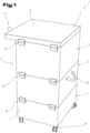
- a preferred embodiment variant of a device 1 for separating a substance from a gas (hereinafter referred to simply as device 1) is shown.
- the device 1 can also be referred to as an air filter.
- the device 1 can be used, for example, to separate solids from the exhaust air from welding systems (so-called welding fumes), from soldering systems, from flame and plasma cutting systems, from laser systems, from grinding dust, for cleaning oil and emulsion mist, paint mist, etc.
- the particles can be separated into different fractions, for example as coarse dust and fine dust.
- These applications of the device 1 are to be understood as examples and are not to be understood as limiting the range of applications of the device 1 .
- the device 1 can also be used to separate a gas from a gas stream.
- the device 1 after 1 comprises a suction module 2, a connection module 3 and two filter modules 4, 5 or consists of them.
- one of two different numbers of filter modules 4, 5 can be provided in the device 1, for example only one or three or four or five, etc.
- the suction module 2, the at least one filter module 4 or the filter modules 4, 5 and the connection module 3 are arranged one above the other, with the at least one filter module 4 or the filter modules 4, 5 being arranged between the suction module 2 and the connection module 3.
- the intake module 2 is connected to the connection module 3 exclusively via the filter module 4 or the plurality of filter modules 4, 5, so that there is no further connecting element between them.
- a connecting element such as a connecting bracket or at least one screw connection, etc., in addition or as an alternative to the connection via the filter module(s) 4, 5.
- the modules of the device 1 are arranged one above the other like a tower.
- the suction module 2 is preferably the lowest module of the device 1, but can optionally also be arranged at a different point in the device 1, for example at the very top.
- Suction module 2 hides the technology of device 1, i.e. for example at least one suction device, such as a fan, a control and/or regulating device, etc. Since these technical components are known from such air filter systems or devices 1, please refer to further details referred to the relevant state of the art.
- connection module 3 preferably forms the upper end of the device 1, but can also be arranged at a different point in the device 1.
- the connection module 3 has at least one inlet 6 .
- the contaminated gas for example the contaminated air
- the inlet 6 can be provided for the connection of a line for the contaminated gas or an extraction device, for example an extraction hood.
- the inlet 6 is arranged on the side of the connection module 3. But it can also be arranged at the top.
- the device 1 can also have more than one suction module 2 and/or more than one connection module 3 .
- the at least one inlet 6 of the connection module housing 8 are oriented or formed accordingly.
- the inlet 6 can be formed by a tube that is open at the bottom.
- the suction module 2 has a suction module housing 7 and the connection module 3 has a connection module housing 8 .
- the intake module housing 7 and the connection module housing 8 can be made of metal, for example, in particular sheet metal.
- the suction module housing 7 and the connection module housing 8 are part of a housing 9 of the device 1, which forms the outer shell of the device 1.
- the filter module 4 is shown.
- the filter modules 4, 5 of a device 1 can be of the same design in principle, so that only one filter module 4 is described below.
- the filter module 4 has at least one filter element 10 . More than one filter element 10 can also be arranged in the filter module 4, for example two directly one above the other or at a distance from one another.
- filter element 10 there is more than one filter element 10 per filter module 4, these can be of the same or different design. In particular, they can have a different permeability for solid particles, ie have a different filter class.
- filter modules 4, 5 are arranged in the device, then these can (exclusively) differ in filter elements 10 that belong to different filter classes, so that, for example, coarse and fine dust separation with the device 1 is possible.
- the structural design of the filter modules can be the same or possibly also different, for example by the filter modules 4, 5 having different heights.
- the at least one filter element 10 is held in a frame 11 of the filter module 4 and is not detachably (inseparably) connected to it.
- non-detachable means that the filter element 10 cannot be separated from the frame without destroying the filter element 10 and/or the connecting means, as is the case with detachable connections.
- the filter element 10 can be cohesively connected to the frame 11 be, for example glued or welded, for example by means of a thermoplastic material.
- other connection methods can also be used, for example the filter element 10 can be riveted or sewn onto the frame 11, etc.
- the filter element 10 can be arranged adjacent to or resting on a web 12 or can be arranged engaging in a groove of this web 12 .
- the web 12 or corresponding parts thereof is/are preferably formed in one piece with the frame 11 or frame walls 13 .
- the frame 11 may be formed from a single frame wall 13, the opposite faces of which are joined together to form the frame 11 (i.e. a shell).
- the frame 11 can also be formed from a plurality of frame walls 13 which are connected to one another, for example materially, e.g. glued, and/or form-fitting and/or force-fitting, e.g. by screws or rivets.
- the frame 11 defines an open area surrounded by the frame 11 .
- the filter element 10 occupies this free area entirely, so that the gas to be cleaned must necessarily flow through the filter element 10 .
- the filter element 10 is preferably planar, for example in the form of a plate. It can consist of a filter fabric or a paper filter or another filter material known for the purposes mentioned, such as activated carbon (for gases) and optionally have a support structure if the inherent rigidity is not sufficient.
- the filter element 10 can, for example, have an area of between 5 m 2 and 40 m 2 . However, this information is not to be understood as limiting.
- the frame 11 forms part of the housing 9, so that the filter module 4 is not used in an additional housing.
- the housing of the device 1 according to Fig.1 formed from the suction module housing 7, the connection module housing 8 and the at least one frame 11 of the at least one filter module 4, 5.
- the frame 11 can have a height 14 suitable for the function of the filter module 4 .
- the height 14 can be, for example, between 10 cm and 60 cm, in particular between 10 cm and 40 cm. “Appropriately” means that the filter module 4 should also have sufficient volume to accommodate substances separated from the gas.
- the frame 11 can therefore be designed, for example, in the form of a shell of a cuboid or generally in the form of a shell. In the context of the invention, the term "frame 11" is therefore not necessarily to be understood in such a way that it is formed relatively flat in the manner of a picture frame and is composed of strips.
- the frame 11 can consist of a metallic material. In the preferred embodiment, however, the frame consists partially or entirely of a non-metallic material.
- a fiber material is particularly preferably used, such as a wood fiber material, e.g. MDF boards, or materials made of cellulose or ground wood or waste paper, such as in particular cardboard or corrugated cardboard.
- thermoplastic or duroplastic plastics can also be used, for example in the form of plastic sheets or multi-wall sheets, etc.
- An end face 15 of the frame 11 can be designed or provided with at least one form-fitting element, for example stepped, groove-shaped, with a web, etc..
- the two axial end faces 15 of the frame 11 can each have complementary form-fitting elements, so that a form-fitting connection is formed between a plurality of filter modules 4, 5 placed one on top of the other.
- the filter modules 4, 5 of a device 1 preferably have the same cross-sectional shape and cross-sectional size, so that the device 1 is preferably cuboid.
- some or all of these modules can be positively connected to one another.
- the clamping closures 16 per se can correspond to the state of the art for this purpose be trained. As is known, when they are closed, they exert a tensile force which causes the parts connected thereto to be tightened.
- the toggle fasteners 16 may include a hook member and a shackle member, with the shackle member being hooked onto the hook member for closure and being closed with a pivoting motion.
- the bracket element and the hook element are each attached to different modules of the housing 9 of the device 1 .
- the clamping closures 16 can optionally have a security element against unintentional opening.
- the non-positive connection between the modules of the housing 9 of the device 1 can also be made differently, for example by screws, toggle levers, using an eccentric connector consisting of a rotatable eccentric in which the head of a bolt is accommodated, the eccentric in a first module and the bolt are arranged in a second module directly adjoining the first module (as is known for the connection of furniture carcass panels), etc.
- the individual modules of the device 1 are connected to one another in a sealed manner, so that no gas flow escapes between the modules when the device 1 is in operation.
- a sealing element in particular an elastomer seal, can be arranged between the modules.
- the sealing element 17 can also be integrally formed on the frame 11 of the filter module 4, preferably on one of the end faces 15. Both end faces 15 can also be provided with an integrally formed sealing element 17.
- the sealing element 17 can, for example, also be partially accommodated in a groove of the end face 15 .
- the molding itself can take place, for example, by means of injection molding or by spraying onto the frame 11, etc.
- the handling element 18 can be a handle or a loop or a band, etc. It is also possible for the handling element 18 to be formed in the frame 11 itself, for example as a recessed grip. The latter can optionally also be used as a counterpart for a clamping closure 16, particularly if the recessed grip is executed undercut.
- the loop or the band can be attached to the outside and/or inside of the respective module.
- a cover element can be provided.
- the cover element can be placed, for example, on the end face 15 of the frame 11 , possibly covering the frame 11 .
- a slot can also be provided in a frame wall 13, into which the cover element is pushed before the removal of the filter module 4 from the device 1, and the filter element 10 is thus covered. This slot can be provided with a destructible cover, e.g.
- a seal can be arranged between the cover element and the frame 11 in order to achieve a tight closure of the filter module 4.
- the seal can be formed by the sealing element 17 mentioned above.
- the seal can also be placed separately or connected to the cover element, for example glued or molded on.
- cover element can be connected to the frame 11, for example via one of the above-mentioned positive and/or non-positive connection elements for connecting the modules of the device 1 to one another, such as the clamping lock 16, etc.
- a hose 20 is also shown.
- This hose 20 is arranged on the frame 11 and has at least one flow connection in the space 21 (volume) of the filter module 4 surrounded by the frame 11. It is thus possible to measure the differential pressure of the filter resistance.
- the degree of contamination of the filter element 10 can be inferred from the filter resistance. The higher the resistance is compared with the value of a filter element 10 of the same filter class, the more material filtered from the gas is in/on the filter element 10.
- the hose 20 is connected to a pressure measuring device, not shown in any more detail, in particular a differential pressure sensor.
- Two measuring points 22, 23 are to be provided for the differential pressure measurement.
- Each of the measuring points 22, 23 has a hose 20.
- At least two hoses 20 or measuring points 22, 23 are therefore preferably arranged per filter module 4, 5, as can be seen in FIGS Figures 2 and 3 is evident.
- the measuring point 22 and thus a hose 20 is arranged below the filter element 10 and the measuring point 23 and thus a hose 20 is arranged above the filter element 10 .
- the hose 20 or hoses 20 can be arranged in a protective tube. Instead of the hoses 20 or in flow connection with them, other line elements, such as pipes, etc., can also be arranged.
- At least one flow channel 24 is arranged within at least one of the frame walls 13 .
- two such flow channels 24 per filter module 4, 5 are provided.
- the flow channel 24 extends or the flow channels 24 preferably extend in the vertical direction.
- the flow channel 24 or the flow channels 24 has a flow connection 25 into the space 21 of the filter module 4, the flow channels 24 each having separate flow connections 25 and the flow channels 24 not being connected to one another in order to obtain the correct value at the respective measuring point 22, 23 to capture.
- the flow channel 24 or the flow channels 24 and/or the flow connections 25 can be introduced into the filter module 4 or the filter modules 4, 5 in the form of bores. However, it or they can also already have been correspondingly formed during the production of the filter module 4 or the filter modules 4, 5.
- the flow channel 24 or the flow channels 24 and/or the flow connections 25 can have a round or a square or generally polygonal cross section.
- the flow channel 24 or the flow channels 24 extend over the entire height of a filter module 4, at least one of the two exit points in the frame 11, for example the upper one, can be closed with a sealing element 26.
- the sealing element can be formed, for example, by the sealing element 17 or the elastomer seal, with which the filter modules 4, 5 can be arranged in a sealing manner against one another, as was explained above.
- At least one of the flow channels 24 in the frame wall of a filter module 4 can be flow-connected to a flow channel 24 in the (same) frame wall 13 .
- the flow connection of the flow channels 24 can be formed automatically when the filter modules 4, 5 are arranged one on top of the other, so that a continuous flow channel 24 through a plurality of filter modules 4, 5 is formed.
- the sealing element 26 can accordingly be arranged differently or provided with a recess in order to allow this flow connection.
- a flow connection can be established between the filter modules 4, 5 (in particular between immediately adjacent filter modules 4, 5) via a further flow connection element (e.g. a hose).
- a further flow connection element e.g. a hose
- the exemplary embodiments show or describe possible embodiment variants of the device 1 for separating a (solid) substance from a gas, it being noted at this point that combinations of the individual embodiment variants with one another are also possible.
Landscapes
- Chemical & Material Sciences (AREA)
- Chemical Kinetics & Catalysis (AREA)
- Filtering Of Dispersed Particles In Gases (AREA)
Applications Claiming Priority (1)
| Application Number | Priority Date | Filing Date | Title |
|---|---|---|---|
| ATA50801/2021A AT524869B1 (de) | 2021-10-06 | 2021-10-06 | Vorrichtung zur Abtrennung eines Stoffes aus einem Gas |
Publications (1)
| Publication Number | Publication Date |
|---|---|
| EP4163004A1 true EP4163004A1 (fr) | 2023-04-12 |
Family
ID=83439148
Family Applications (1)
| Application Number | Title | Priority Date | Filing Date |
|---|---|---|---|
| EP22197588.1A Pending EP4163004A1 (fr) | 2021-10-06 | 2022-09-23 | Dispositif pour séparer une substance d'un gaz |
Country Status (2)
| Country | Link |
|---|---|
| EP (1) | EP4163004A1 (fr) |
| AT (1) | AT524869B1 (fr) |
Families Citing this family (2)
| Publication number | Priority date | Publication date | Assignee | Title |
|---|---|---|---|---|
| SE546250C2 (en) * | 2022-11-29 | 2024-09-10 | Absolent Ab | Air filtering device |
| SE546249C2 (en) * | 2022-11-29 | 2024-09-10 | Absolent Ab | Air filtering device |
Citations (5)
| Publication number | Priority date | Publication date | Assignee | Title |
|---|---|---|---|---|
| WO1997040917A1 (fr) * | 1996-04-26 | 1997-11-06 | Donaldson Company, Inc. | Dispositif de filtrage en ligne |
| DE19645096A1 (de) | 1996-11-01 | 1998-05-07 | Clinix Gmbh | Luftreinigungsgerät |
| DE10337652A1 (de) * | 2003-08-16 | 2005-03-10 | Mahle Filtersysteme Gmbh | Gas-Filter, insbesondere Luftansaugfilter eines Nutzkraftfahrzeuges |
| US20060021932A1 (en) * | 2004-07-26 | 2006-02-02 | Darnell Justin R | Integrated flat panel filter and housing |
| US20200188827A1 (en) * | 2018-12-13 | 2020-06-18 | Shenzhen Chenbei Technology Co., Ltd. | Air Filtering System |
Family Cites Families (6)
| Publication number | Priority date | Publication date | Assignee | Title |
|---|---|---|---|---|
| DE4128747A1 (de) * | 1991-08-29 | 1993-03-04 | Refil Gmbh Filtertechnik & Rec | Filter zur teilchenabscheidung |
| IL146570A0 (en) * | 2001-01-03 | 2002-11-10 | Mcgill Joseph A | Modular clean room filter system |
| CN207962955U (zh) * | 2018-02-07 | 2018-10-12 | 山东永华净化科技有限公司 | 塔式空气净化器 |
| CN210473453U (zh) * | 2019-07-29 | 2020-05-08 | 宁波艾普罗环保科技有限公司 | 一种用于空调机组内电袋合一的空气过滤器 |
| CN212818674U (zh) * | 2020-05-13 | 2021-03-30 | 苏州佳洁空气过滤器有限公司 | 一种多袋式空气过滤器 |
| CN112354317A (zh) * | 2020-11-11 | 2021-02-12 | 精劲精密机械南通有限公司 | 一种空气过滤除尘装置 |
-
2021
- 2021-10-06 AT ATA50801/2021A patent/AT524869B1/de active
-
2022
- 2022-09-23 EP EP22197588.1A patent/EP4163004A1/fr active Pending
Patent Citations (5)
| Publication number | Priority date | Publication date | Assignee | Title |
|---|---|---|---|---|
| WO1997040917A1 (fr) * | 1996-04-26 | 1997-11-06 | Donaldson Company, Inc. | Dispositif de filtrage en ligne |
| DE19645096A1 (de) | 1996-11-01 | 1998-05-07 | Clinix Gmbh | Luftreinigungsgerät |
| DE10337652A1 (de) * | 2003-08-16 | 2005-03-10 | Mahle Filtersysteme Gmbh | Gas-Filter, insbesondere Luftansaugfilter eines Nutzkraftfahrzeuges |
| US20060021932A1 (en) * | 2004-07-26 | 2006-02-02 | Darnell Justin R | Integrated flat panel filter and housing |
| US20200188827A1 (en) * | 2018-12-13 | 2020-06-18 | Shenzhen Chenbei Technology Co., Ltd. | Air Filtering System |
Also Published As
| Publication number | Publication date |
|---|---|
| AT524869A4 (de) | 2022-10-15 |
| AT524869B1 (de) | 2022-10-15 |
Similar Documents
| Publication | Publication Date | Title |
|---|---|---|
| EP4163004A1 (fr) | Dispositif pour séparer une substance d'un gaz | |
| DE19747337C2 (de) | Siebsystem und Verfahren zum Sieben und Trocknen | |
| EP3411129B1 (fr) | Élément filtrant, cadre d'un élément filtrant, soufflet filtrant d'un élément filtrant, boîtier de filtre et filtre | |
| EP1787562B1 (fr) | Raccord avec dispositif de déviation pour un aspirateur | |
| DE68914063T2 (de) | Filterpatronenbefestigung für einen Staubsammler. | |
| EP2020259B1 (fr) | Boîte d'agent déshydratant destinée à la déshumidification d'air | |
| EP0839538A2 (fr) | Appareil pour la purification de l'air | |
| EP0562502B1 (fr) | Cartouche filtrante encastrable | |
| DE60119935T2 (de) | Filterapparat und methode | |
| EP2851110A1 (fr) | Élément de filtre et système de filtre équipé d'un élément de filtre | |
| DE102018103019A1 (de) | Vorrichtung zum Abscheiden von Overspray | |
| WO2010040368A1 (fr) | Masque de protection respiratoire | |
| DE2540141C3 (de) | Filteranlage zum Reinigen von Gas- oder Luftströmen | |
| DE102016001486B4 (de) | Vorrichtung zum Filtrieren von verunreinigter Luft und Filtermodul zur Verwendung in einer solchen Vorrichtung | |
| WO2017133798A1 (fr) | Boîtier de filtre et filtre | |
| WO2016131435A1 (fr) | Module filtrant | |
| EP2520722B1 (fr) | Console de jonction et pilon doté de cette console de jonction ainsi que leur procédé de fabrication | |
| EP2918939B1 (fr) | Cartouche filtrante pour une hotte de sécurité et hotte de sécurité dotée d'au moins une cartouche filtrante | |
| DE102010006556B4 (de) | Luftfilter eines Verbrennungsmotors | |
| DE3248891C2 (de) | Luftfilter | |
| EP1312871A1 (fr) | Etabli de sécurité | |
| WO2017133797A1 (fr) | Élément filtrant, cadre de filtre d'un élément filtrant, soufflet filtrant d'un élément filtrant et filtre | |
| AT403892B (de) | Vorrichtung zur befestigung von filterschläuchen eines schlauchfilters an einem rüttelrahmen | |
| DE2034753C3 (de) | Faltenbalg | |
| DE4339758A1 (de) | Trocknungspatrone für Lufttrocknungsanlagen, insbesondere für Druckluftbremsanlagen von Fahrzeugen |
Legal Events
| Date | Code | Title | Description |
|---|---|---|---|
| PUAI | Public reference made under article 153(3) epc to a published international application that has entered the european phase |
Free format text: ORIGINAL CODE: 0009012 |
|
| STAA | Information on the status of an ep patent application or granted ep patent |
Free format text: STATUS: THE APPLICATION HAS BEEN PUBLISHED |
|
| AK | Designated contracting states |
Kind code of ref document: A1 Designated state(s): AL AT BE BG CH CY CZ DE DK EE ES FI FR GB GR HR HU IE IS IT LI LT LU LV MC MK MT NL NO PL PT RO RS SE SI SK SM TR |
|
| STAA | Information on the status of an ep patent application or granted ep patent |
Free format text: STATUS: REQUEST FOR EXAMINATION WAS MADE |
|
| 17P | Request for examination filed |
Effective date: 20231002 |
|
| RBV | Designated contracting states (corrected) |
Designated state(s): AL AT BE BG CH CY CZ DE DK EE ES FI FR GB GR HR HU IE IS IT LI LT LU LV MC MK MT NL NO PL PT RO RS SE SI SK SM TR |
|
| STAA | Information on the status of an ep patent application or granted ep patent |
Free format text: STATUS: EXAMINATION IS IN PROGRESS |
|
| 17Q | First examination report despatched |
Effective date: 20231206 |