EP4162108B1 - Mahlgarnitursegment für einen refiner - Google Patents
Mahlgarnitursegment für einen refiner Download PDFInfo
- Publication number
- EP4162108B1 EP4162108B1 EP21735742.5A EP21735742A EP4162108B1 EP 4162108 B1 EP4162108 B1 EP 4162108B1 EP 21735742 A EP21735742 A EP 21735742A EP 4162108 B1 EP4162108 B1 EP 4162108B1
- Authority
- EP
- European Patent Office
- Prior art keywords
- blade
- feed groove
- blade segment
- segment
- bars
- Prior art date
- Legal status (The legal status is an assumption and is not a legal conclusion. Google has not performed a legal analysis and makes no representation as to the accuracy of the status listed.)
- Active
Links
Images

Classifications
-
- D—TEXTILES; PAPER
- D21—PAPER-MAKING; PRODUCTION OF CELLULOSE
- D21D—TREATMENT OF THE MATERIALS BEFORE PASSING TO THE PAPER-MAKING MACHINE
- D21D1/00—Methods of beating or refining; Beaters of the Hollander type
- D21D1/20—Methods of refining
- D21D1/22—Jordans
- D21D1/24—Jordan rolls
-
- D—TEXTILES; PAPER
- D21—PAPER-MAKING; PRODUCTION OF CELLULOSE
- D21D—TREATMENT OF THE MATERIALS BEFORE PASSING TO THE PAPER-MAKING MACHINE
- D21D1/00—Methods of beating or refining; Beaters of the Hollander type
- D21D1/20—Methods of refining
- D21D1/30—Disc mills
- D21D1/306—Discs
Definitions
- the invention relates to refiners for refining fibrous material and especially to a blade segment for a refiner for refining fibrous material.
- Refiners used for refining fibrous material comprise typically two refining elements opposite to each other forming a refining gap or a refining chamber therebetween and turning relative to each other, i.e. one or both of them is/are rotating.
- the refining elements comprise refining surfaces provided with blade bars and blade grooves therebetween, the blade bars being intended to defibre and refine the material to be refined and the blade grooves being intended to convey the material to be refined forward along the refining surfaces.
- the refining surface of the refining element is typically formed of several blade segments fastened to a body of the respective refining element. The complete refining surface of the refining element is thus formed of the refining surfaces of several blade segments fastened next to each other in the refining element.
- One type of refiners is a so-called through-fed or through-flow refiner in which the material to be refined is fed to the refining gap not just from one end towards the other end of the refiner but from the middle, too, in other words, through the refining element(s).
- This type of refiner is disclosed in EP 2326767 B1 where the refining element comprises openings providing open area of 5-70% of its refining area.
- Another example is disclosed in EP 3401439 B1 in which the openings are indents on a side edge of the refining segment and the material flow is enhanced by feed grooves.
- An object of the present invention is to provide a novel blade segment for a refiner for refining fibrous material, as well as a novel refiner for refining fibrous material.
- the invention is based on the idea of interlacing the blade bars of the blade segment at the feed groove.
- the interlacing of the blade bars at the feed groove provide at the feed groove a strong blade bar configuration wherein the interlaced blade bars support to each other, thereby preventing a buckling of the blade bars at the feed groove.
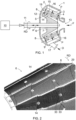
- Figure 1 is a schematic general side view of a general construction of a refiner 1 in cross-section, which refiner may be used for refining a fibrous material, such as a wood material containing lignocellulose or another fibre material suitable to be used for manufacturing paper or paperboard, for example.
- the refiner 1 shown in Figure 1 is of conical type but disc-refiners, conical-disc-refiners and cylindrical refiners could be used as well as an example here.
- a refiner comprises at least two substantially oppositely positioned refining elements at least one of which is rotating, and a refining chamber formed between each two substantially oppositely positioned refining elements. In the following a refiner with only one rotatable refining element is described.
- the refiner 1 of Figure 1 comprises a frame 2 and a stationary, fixed refining element 3, i.e. a stator 3, supported on the frame 2.
- the stator 3 comprises two or more stator blade segments 4, each of them comprising blade bars and blade grooves therebetween.
- the blade bars and the blade grooves in each stator blade segment 4 form a refining surface 5 of the respective blade segment 4, the refining surface 5 of each stator blade segment 4 thereby providing a part of a refining surface of the stator 3.
- a complete refining surface of the stator 3 is formed of the refining surfaces 5 of a necessary number of the blade segments 4 fastened next to each other in the stator 3 so that the complete refining surface 5 extending over the whole circumference of the stator 3 is provided.
- both the refining surface of each single stator blade segment 4 as well as the complete refining surface of the stator 3 are herein denoted with the same reference sign 5.
- the refiner 1 further comprises a rotatable refining element 6, i.e. a rotor 6, of the refiner 1.
- the rotor 6 comprises a hub 7.
- the rotor 6 further comprises two or more rotor blade segments 8 supported to the hub 7, each rotor blade segment 8 comprising blade bars and blade grooves therebetween.
- the blade bars and the blade grooves in each rotor blade segment 8 form a refining surface 9 of the respective blade segment 8, the refining surface 9 of each rotor blade segment 8 thereby providing a part of a refining surface of the rotor 6.
- a complete refining surface of the rotor 6 is formed of the refining surfaces 9 of a necessary number of the blade segments 8 fastened next to each other in the rotor 6 so that the complete refining surface 9 extending over the whole circumference of the rotor 6 is provided.
- both the refining surface of each single rotor blade segment 8 as well as the complete refining surface of the rotor 6 are herein denoted with the same reference sign 9.
- the hub 7 of the rotor 6 is connected to a driving motor 10 by a shaft 11 so that the rotor 6 can be rotated relative to the stator 3 in a direction of arrow RD, for instance, the arrow RD thus indicating an intended rotation direction RD of the rotor 6.
- the refiner 1 may also comprise a loading device which, for the sake of clarity, is not shown in Figure 1 .
- the loading device can be used for moving back and forth the rotor 6 attached to the shaft 11, as schematically shown by arrow A, in order to adjust a size of a refining gap 12, i.e. a refining chamber 12, between the stator 3 and the rotor 6, wherein the fibrous material is actually refined.
- the fibrous material to be refined is fed into the refiner 1 via a feed channel 13 in a manner shown by arrow F.
- most of the fibrous material fed into the refiner 1 passes, in a manner schematically shown by arrows P, through openings 14 formed in the rotor blade segments 8 into the refining chamber 12, wherein the fibrous material is to be refined.
- most of the already refined fibrous material is, in turn, discharged through openings 15 formed in the stator blade segments 4 into an intermediate space 16 between the frame 2 of the refiner 1 and the stator 3, wherefrom the refined material is removed via a discharge channel 17 from the refiner 1, as schematically shown by arrow D.
- some of the fibrous material to be fed into the refiner 1 may transfer into the refining chamber 12 from the right end of the refining chamber 12, i.e. from a first end 18 or an inner end 18 of the refiner 1 having a smaller diameter, as seen in Figure 1 .
- some of the already refined material may also exit the refining chamber 12 from the left end of the refining chamber 12, i.e. from a second end 19 or an outer end 19 of the refiner 1 having a larger diameter, as seen in Figure 1 , wherefrom a connection is provided to the intermediate space 16.
- first end 18 of the refiner 1 In the embodiment of Figure 1 of the refiner 1, only one feed channel 13 is provided, and it is arranged at the first end 18 of the refiner 1 having the smaller diameter.
- the actual implementation of the refiner could also comprise a second feed channel arranged at the second end 19 of the refiner 1 having the larger diameter, whereby the discharge channel 17 of the refiner 1 could be arranged for example somewhere between the first 18 and second 19 ends of the refiner 1.
- the reference sign 18 and the term first end 18 or the term inner end 18 may indicate both the first end 18 or the inner end 18 of the refiner 1 having the smaller diameter and the first end 18 or the inner end 18 of the refining element 3, 6 or of the refining chamber 12 having the smaller diameter.
- the reference sign 19 and the term second end 19 or the term outer end 19 may indicate both the second end 19 or the outer end 19 of the refiner 1 having the larger diameter and the second end 19 or the outer end 19 of the refining element 3, 6 or of the refining chamber 12 having the larger diameter.
- the blade segment of the solution described herein may be applied in other kind of conical refiners too.
- the blade segment of the solution described herein is applicable to disc refiners and cylindrical refiners and to refiners comprising both a conical portion and a disc portion, as well.
- Figure 2 is a schematic upper oblique view of a part of a set of neighbouring rotor blade segments 8 and Figure 3 is a schematic upper oblique view of a rotor blade segment 8 applicable to be used for forming a part of the refining surface 9 of the rotor 6.
- the blade segment structure is considered in more detail in view of the rotor blade segment 8 but the structure of the stator blade segment 4 is substantially similar unless otherwise disclosed.
- the blade segment 8 comprises an inner end edge 20 or a first end edge 20 to be directed towards the inner end 18 of the rotor 6 having the smaller diameter.
- the blade segment 8 further comprises an outer end edge 21 or a second end edge 21 to be directed towards the outer end 19 of the rotor 6 having the larger diameter.
- the inner end edge of the blade segment provides an axially inner end of the blade segment and the outer end edge of the blade segment provides an axially outer end of the blade segment, the direction from the axially inner end towards the axially outer end providing the longitudinal axis of the blade segment, the longitudinal axis of the blade segment shown schematically in Figure 3 by an arrow LA.
- the inner end edge of the blade segment would provide a radially inner end of the blade segment and the outer end edge of the blade segment would provide a radially outer end of the blade segment, the direction from the radially inner end towards the radially outer end thus providing the longitudinal axis of the blade segment.
- the blade segment 8 further comprises a first side edge 22 or a leading side edge 22 extending from the inner end edge 20 of the blade segment 8 up to the outer end edge 21 of the blade segment 8 and providing the side edge of the blade segment 8 which is the first to meet an edge of a counter blade segment, thus it is directed towards the intended rotation direction RD of the rotor 6.
- the blade segment 8 further comprises a second side edge 23 or a trailing side edge 23 opposite to the first side edge 22 and extending from the inner end edge 20 of the blade segment 8 up to the outer end edge 21 of the blade segment 21 and providing the side edge of the blade segment 8 which is the last to meet an edge of a counter blade segment, thus it is directed towards the direction that is opposite to the intended rotation direction RD of the rotor 6.
- the inner 20 and the outer 21 end edges together with the first 22 and second 23 side edges define a periphery of the blade segment 8.
- the blade segment 8 comprises a body 24 having a front surface 25 to be directed towards the refining chamber 12 of the refiner 1 and a background surface 26 to be directed towards the hub 7 of the rotor 6.
- the front surface 25 of the blade segment body 24 is provided with blade bars 27 and blade grooves 28 which together provide the refining surface 9 of the blade segment 8.
- the blade bars 27 are intended to defibre and refine the material to be refined and the blade grooves 28 are intended to convey the material to be refined forward along the refining surface 9.
- the blade segment 8 further comprises fastening holes 31, 32 intended to receive fastening means, like bolts, for fastening the blade segment 8 to the hub 7 of the rotor 6, or any supporting structures directly or via supporting means, like fixing rings 33.
- the blade segment 8 further comprises, at corners thereof, extensions or shoulder portions 34, 35, 36, 37 at which the blade segments 8 are in mutual sidewise contact to its neighbouring blade segment 8 and thereby possibly supported to each other.
- the blade segment according to the solution disclosed herein is used in a through-fed refiner, it is provided with openings so as to allow the pulp feeding/discharge through a refining surface of the stator and/or the rotor.
- the openings are arranged at least at one side edge of the blade segment in the middle portion of the longitudinal axis of the blade segment.
- the bevel 22c is arranged to deviate, at the first side edge 22, from the direction of the longitudinal axis LA of the blade segment 8 away from the centre part of the blade segment 8, i.e. to an opposite direction with respect to the longitudinal axis LA of the blade segment 8 than the long side edge portions 22a, 22c.
- the bevels 22c could be extended to touch the neighbouring segment.
- the slit or bay at the first side edge 22 of the blade segment 8 is arranged such that the first side edge 22 does not form a completely straight line between the shoulder members 34, 36 at the inner end edge 20 and the outer end edge 21 but forms a longitudinal slit or bay with gentle zigzag or lightning shape edge.
- This slit or bay at the first side edge 22 of the blade segment 8 provides the opening 14 at the first side edge 22 of the blade segment 8.
- This opening 14 extends from the front surface 25 of the blade segment 24 up to the rear or background surface 26 of the blade segment body 24, thus extending through a whole thickness of the blade segment 8 or the blade segment body 24.
- the blade segment 8 comprises substantially similar openings 14 on both side edges 22, 23 of the blade segment 8, as can be seen in Figure 2 , so that the opening at the second side edge 23 extends also from the second side edge 23 towards the opposite first side edge 22 such that the second side edge 23 does not also form a completely straight line between the inner end edge 20 and the outer end edge 21.
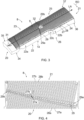
- FIG. 5 is a schematic upper planar view of another blade segment 8.
- the first side edge 22 of the blade segment 8 comprises a number of openings 14, each having form of an indent that extends from the first side edge 22 towards the opposite second side edge 23.
- the openings 14 extend from the front surface 25 of the blade segment body 24 up to the rear or background surface 26 of the blade segment body 24, the openings 14 thus extending through a whole thickness of the blade segment 8 or the blade segment body 24.
- the blade segment 8 may comprise one or more similar openings 14, i.e. indents, that extend from the second side edge 23 towards the opposite first side edge 22 such that the second side edge 23 does not also form a completely straight line between the inner end edge 20 and the outer end edge 21.
- the blade segments 8 of Figures 3 and 5 or the refining surface 9 of the blade segments 8 of Figures 3 and 5 further comprise feed grooves 29.
- the feed groove 29 is arranged to extend from the opening 14 arranged in the first side edge 22 of the blade segment 8 towards at least one other edge of the blade segment 8, in the embodiments of Figures 3 and 5 towards the second side edge 23 of the blade segment 8, such that the feed groove 29 crosses the blade bars 28 and the blade grooves 29.
- the feed groove 29 has a first end 29a at the opening 14 and a second end 29b facing away from the opening 14.
- the feed groove 29 form a flow connection so that the material to be refined and supplied from the side of the background surface 26 of the blade segment 8 towards the front surface 25 of the blade segment 8 through the opening 14 enters into the feed groove 29 and flows along the feed groove 29 towards a central portion of the blade segment 8, thus feeding the material to be refined across the refining surface 9.
- forces affecting on the material flowing in the feed groove 29 force the material away from the feed groove 29 into the blade grooves 28 remaining between the blade bars 27, thus distributing the material to be refined on the refining surface 9 of the blade segment 8.
- the feed or supply of the material through the opening 14 in the side edge 22 of the blade segment 8 causes the material to flow on the refining surface 9 immediately at least partly along a peripheral direction of the refining surface 9, without a need to turn the flow of the supplied material from an axial or radial direction to at least partly rotational motion along the peripheral direction of the refining surface as it takes place in the refiners wherein the feed or supply of the material takes place over the inner end edge of the blade segment.
- the feed groove 29 has its first end 29a at the slit or bay on the first side edge 22 of the blade segment 8 and the second end at the slit or bay or close to it on the second side edge 23 of the blade segment 8, i.e. the opposite side edge 23 of the blade segment 8.
- the first end 29a of the feed groove 29 is located in the vicinity of a fixing ring, preferably just before or after the fixing ring at which the blade segment is to be assembled to the respective refining element.
- the feeding grooves 29 enhance the pulp flow over the refining surface specifically in the vicinity of those areas of the slit where the fixing rings make interruption to the otherwise continuous slit preventing thus pulp from reaching freely the refining surface as well as around the bolt holes.
- the first end 29a of the feed groove 29 would preferably locate in the vicinity of the shoulder and the groove 29 would extend over the bolt hole.
- the blade bars 27 are interlaced at the feed groove 29.
- the interlacing of the blade bars 27 at the feed groove 29 means, referring in more detail to an embodiment of Figure 4 , that the blade bars 27 at one side of the feed groove 29 in respect of the longitudinal axis LA of the blade segment 8 are arranged to extend into the blade grooves 28 between the blade bars 27 at the opposite side of the feed groove 29 in respect of the longitudinal axis LA of the blade segment 8 and vice versa.
- FIG. 4 An embodiment of the interlacing of the blade bars 27 is shown in more detail in Figure 4 , wherein Figure 4 is a schematic upper oblique view of a feed groove 29 in the rotor blade segment 8. Similar interlacing of the blade bars 27 may also be applied also in the blade segment of Figure 5 , wherein, for enhancing the visibility of the path the feed groove, the blade bars 27 have not been drawn at the feed groove 29.
- first blade bars 27a extending from the direction of the inner end edge 20 of the blade segment 8 towards the feed groove 29 and up to the feed groove 29 as well as first blade grooves 28a between the first blade bars 27a.
- second blade bars 27b extending from the direction of the feed groove 29, i.e. from the feed groove 29, at least partly towards the outer end edge 21 of the blade segment 8 as well as second blade grooves 28b between the second blade bars 27b.
- the first blade bar 27a has an end 27a' facing towards the outer end edge 21 of the blade segment 8, i.e. towards the second blade bars 27b, and extending into the second blade groove 28b between two neighbouring second blade bars 27b.
- the second blade bar 27b has an end 27b' facing towards the inner end edge 20 of the blade segment, i.e. towards the first blade bars 27a, and extending into the first blade groove 28a between two neighbouring first blade bars 27a.
- the ends 27a', 27b' of the blade bars 27a, 27b in the embodiment of Figure 4 are linearly downwards descending sloping surfaces that are arranged to partly interlace with each other such that the downwards descending sloping end 27a' of the first blade bar 27a partly extends into the second blade groove 28b between two neighbouring or adjacent second blade bars 27b and the downwards descending sloping ends 27b' thereof, and correspondingly, the downwards descending sloping end 27b' of the second blade bar 27b partly extends into the first blade groove 28a between two neighbouring or adjacent first blade bars 27a and the downwards descending sloping ends 27a' thereof.
- the oppositely directed ends 27a', 27b' of the first 27a and the second 27b blade bars are thus arranged to extend into the oppositely positioned blade grooves 28a, 28b between the oppositely positioned blade bars 27a, 27b by turns.
- the oppositely directed linearly downwards descending sloping ends 27a', 27b' of the first 27a and the second 27b blade bars form or provide an upwards opening V-shaped feed groove 29.
- the ends 27a', 27b' of the blade bars 27a, 27b could alternatively be for example in a convex manner or in a concave manner downwards descending sloping surfaces so as to form or provide an upwards opening feed groove 29 between the oppositely directed ends 27a', 27b of the first 27a and the second 27b blade bars.
- the feed groove 29 could have a U-shape profile or even a profile resembling a flying bird silhouette.
- the interlaced blade bars 27, 27a, 27b at the feed groove 29 make a stronger blade bar configuration wherein the interlaced blade bars 27, 27a, 27b or the ends thereof support to each other at the feed groove 29, thereby preventing a buckling of the blade bars at the feed groove 29.
- the interlaced blade bars 27 at the feed groove 29 also equalize a cutting-edge length of the blade segment 8 when the blade bars wear down. Additionally, there are at the feed groove 29 more blade bar material to wear, thereby improving the lifetime of the blade segment.
- the material to be refined is fed from the background surface 26 side of the blade segment 8 through the opening 14 into the feed groove 29 from the first end 29a of the feed groove 29.
- the material flows along the feed groove 29 from the first end 29a of the feed groove 29 towards the second end 29b of the feed groove 29 and, at the same time, the material is distributed from the feed groove 29 into the blade grooves 28 between the blade bars 27 and on top of the blade bars 27 into the refining chamber 12 between the stator 4 and rotor 8 blade elements.
- a volume of the feed groove 29 is arranged to decrease along its path from the first end 29a of the feed groove 29a towards the second end 29b.
- the decreasing volume of the feed groove 29 refers to a decreasing cross-sectional area of the feed groove from the first end 29a of the feed groove 29 towards the second end 29 thereof.
- the decreasing volume of the feed groove 29 towards the second end thereof effectively forces the material to be refined and fed into the feed groove 29 to exit from the feed groove 29 into the blade grooves 28 between the blade bars 27 and on top of the blade bars 27 into the refining chamber 12 between the stator 4 and rotor 8 blade elements.
- the volume of the feed groove 29 may decrease from the first end 29a of the feed groove 29 towards the second end 29b of the feed groove 29 either substantially continuously from a preceding blade bar to a succeeding blade bar along the feed groove, or stepwise.
- the decreasing volume of the feed groove in the longitudinal direction thereof is provided by arranging an angle of the downwards descending sloping ends of the interlaced blade bars relative to a normal of the refining surface at the feed groove to decrease along the feed groove from the first end of the feed groove towards the second end of the feed groove.
- Figures 6a and 6b An example of the embodiment like that is shown schematically in Figures 6a and 6b , wherein Figure 6a shows schematically an interlacing of the blade bars 27a, 27b at a first end 29a of the feed groove 29 and Figure 6b shows schematically an interlacing of the blade bars 27a, 27b at a second end 29b of the feed groove 29.
- Figures 6a and 6b show the first blade bar 27a and the end 27a' thereof, that lies partly behind the second blade bar 27b and the end 27b' thereof, as shown schematically by broken lines in Figures 6a and 6b .
- Further Figures 6a and 6b show the normal 30 of the refining surface 9 of the blade segment 8 at the feed groove 29, and, in Figure 6a an angle a 1 between the normal 30 and the downwards descending end 27a' of the first blade bar 27a and an angle b 1 between the normal 30 and the downwards descending end 27b' of the second blade bar 27b at the first end 29a of the feed groove 29, as well as in Figure 6b an angle az between the normal 30 and the downwards descending end 27a' of the first blade bar 27a and an angle b 2 between the normal 30 and the downwards descending end 27b' of the second blade bar 27b at the second end 29b of the feed groove 29.
- the embodiment of the feed groove 29 of Figures 6a and 6b has the effect of decelerating the flow of the material out of the feed groove, thereby allowing a substantially even flow of the material out of the feed groove by preventing burst-like escapes of the material out of the feed groove. At the same time, it increases the total cutting-edge length of the blade bars and therefore increases the total cutting-edge length of the complete refining surface.
- the normal 30 of the refining surface 9 of the blade segment 8 at the feed groove 29 forms a centre line of the feed groove 29 in such a way that the angle between the normal 30 and the downwards descending end 27a' of the first blade bar 27a and the angle between the normal 30 and the downwards descending end 27b' of the second blade bar 27b are substantially equal along the feed groove 29.
- the angles a 1 and b 1 are substantially equal relative to each other and the angles a 2 and b 2 are substantially equal relative to each other.
- the angle between the normal 30 and the downwards descending end 27a' of the first blade bar 27a and the angle between the normal 30 and the downwards descending end 27b' of the second blade bar 27b may be arranged to be different from each other.
- the angles a 1 and b 1 could be arranged to be more or less different from each other and the angles a 2 and b 2 could be arranged to be more or less different from each other.
- the flow of the material to be refined out from the feed groove 29 may be controlled in different ways at different portions along the feed groove 29 by intentionally forming the angle between the normal 30 and the downwards descending end 27a' of the first blade bar 27a and the angle between the normal 30 and the downwards descending end 27b' of the second blade bar 27b to be different from each other in different ways at different portions along the feed groove 29.
- a vertical position of a plane of incidence of the downwards descending sloping ends of the interlaced blade bars is arranged to be substantially constant along the feed groove.
- the plane of incidence PI is arranged at a distance H from a top surface of the body 24 of the blade segment 8, the top surface of the body 24 of the blade segment 8 shown schematically by the broken line denoted with the reference sign 24'.
- the feed groove is arranged to cross the blade bars and the blade grooves at an angle.
- the feed groove 29 crosses the blade bars 27 and grooves 28 at an angle that is preferably from 90 to ⁇ 45 degrees.
- the effect of this embodiment is a better distribution of the material to be refined from the feed groove 29 into the blade grooves 28 and onto the top surface of the blade bars 27, i.e. into the refining chamber 12.
- the feed groove is curved along its direction of extension.
- the second end 29b of the feed groove 29 is at different position along the longitudinal axis LA of the blade segment than the first end 29a of the feed groove 29.
- the ends 29a, 29b of the feed groove do not locate on the same normal level to the longitudinal axis LA but the first end 29a may locate at one normal level, e.g. closer the first end edge 20 of the blade segment 8, and the second end 29b at another normal level, i.e. farther away from the first end edge 20 of the blade segment 8.
- the advantageous effect of this embodiment is that the pulp flow is guided onto portions of the refining surface 9 not coinciding with the indents at the side edge(s) 22, 23 of the blade segment 8 or to areas of the refining surface 9 that might be less accessible to the pulp flow, like the areas around the fastening holes of the blade segment 8.
Landscapes
- Paper (AREA)
- Crushing And Pulverization Processes (AREA)
Claims (14)
- Mahlgarnitursegment (4, 8) für einen Refiner (1) zum Mahlen von faserigem Material, wobei das Mahlgarnitursegment (4, 8) umfasst:eine erste Endkante (20) und eine zweite Endkante (21),eine erste Seitenkante (22) und eine zweite Seitenkante (23) entgegengesetzt zur ersten Seitenkante (22), wobei die erste Seitenkante (22) und die zweite Seitenkante (23) sich zwischen der ersten Endkante (20) und der zweiten Endkante (21) erstrecken,eine Mahloberfläche (5, 9), die Mahlgarniturstangen (27, 27a, 27b) und Mahlgarniturrillen (28, 28a, 28b) dazwischen an einer vorderen Oberfläche (25) des Mahlgarnitursegments (4, 8) umfasst,mindestens eine Öffnung (14, 15) an mindestens einer Seitenkante (22, 23), wobei die Öffnung sich durch eine gesamte Dicke eines Mahlgarnitursegmentkörpers (24) erstreckt, undmindestens eine Zuführrille (29) an der Mahloberfläche (5, 9), wobei die Zuführrille (29) sich von der Öffnung erstreckt und die Mahlgarniturstangen (27, 27a, 27b) und die Mahlgarniturrillen (28, 28a, 28b) zum Zuführen des zu mahlenden Materials durch die Mahloberfläche (5, 9) kreuzt,dadurch gekennzeichnet, dassdie Mahlgarniturstangen (27, 27a, 27b) des Mahlgarnitursegments (4, 8) an der Zuführrille (29) verflochten sind.
- Mahlgarnitursegment nach Anspruch 1, dadurch gekennzeichnet, dass die Öffnung (14, 15) ein ununterbrochener Schlitz an der Seitenkante (22, 23) zwischen Erweiterungen ist, die an Ecken des Mahlgarnitursegments (4, 8) angeordnet sind.
- Mahlgarnitursegment nach Anspruch 1, dadurch gekennzeichnet, dass die Öffnung (14, 15) eine Kerbe an der Seitenkante (22, 23) ist und sich hin zur entgegengesetzten Seitenkante (22, 23) erstreckt.
- Mahlgarnitursegment nach Anspruch 1, dadurch gekennzeichnet, dass die Mahlgarniturstangen (27, 27a, 27b) an ihren Endteilen, die in entgegengesetzte Richtungen an der Zuführrille (29) gerichtet sind, verflochten sind.
- Mahlgarnitursegment nach Anspruch 4, dadurch gekennzeichnet, dass in entgegengesetzte Richtungen gerichtete verflochtene Enden (27a', 27b') der verflochtenen Mahlgarniturstangen (27a, 27b) nach unten absteigende abfallende Enden (27a', 27b') umfassen, die so angeordnet sind, dass sie die sich nach oben öffnende Zuführrille (29) bilden.
- Mahlgarnitursegment nach Anspruch 5, dadurch gekennzeichnet, dass die Enden (27a', 27b') der verflochtenen Mahlgarniturstangen (27, 27a, 27b) geradlinige nach unten abfallende Enden (27a', 27b') sind, die so angeordnet sind, dass sie eine sich nach oben öffnende V-förmige Zuführrille (29) bilden.
- Mahlgarnitursegment nach einem der vorhergehenden Ansprüche, dadurch gekennzeichnet, dass ein Volumen der Zuführrille (29) so angeordnet ist, dass es von einem ersten Ende (29a) der Zuführrille (29) an der Öffnung (14, 15) hin zu einem zweiten Ende (29b) der Zuführrille (29) abnimmt.
- Mahlgarnitursegment nach Anspruch 7, dadurch gekennzeichnet, dass ein Winkel (a1, a2, b1, b2) des nach unten absteigenden abfallenden Endes (27a', 27b') der Mahlgarniturstange (27, 27a, 27b) in Bezug auf eine Normale (30) der Mahloberfläche (5, 9) an der Zuführrille (29) so angeordnet ist, dass er entlang der Zuführrille (29) vom ersten Ende (29a) der Zuführrille (29) hin zum zweiten Ende (29b) der Zuführrille (29) abnimmt.
- Mahlgarnitursegment nach Anspruch 8, dadurch gekennzeichnet, dass die Winkel (a1, b1; a2, b2) zwischen der Normalen (30) der Mahloberfläche (5, 9) und den nach unten absteigenden abfallenden Enden (27a', 27b') der entgegengesetzten Mahlgarniturstangen (27, 27a, 27b), welche die Zuführrille (29) bilden, gleich sind.
- Mahlgarnitursegment nach einem der Ansprüche 5 bis 9, dadurch gekennzeichnet, dass eine vertikale Position einer Einfallsebene (PI) der verflochtenen nach unten absteigenden abfallenden Enden (27a', 27b') der verflochtenen Mahlgarniturstangen (27, 27a, 27b) so angeordnet ist, dass sie entlang der Zuführrille (29) im Wesentlichen konstant ist.
- Mahlgarnitursegment nach einem der vorhergehenden Ansprüche, dadurch gekennzeichnet, dass die Zuführrille (29) so angeordnet ist, dass sie die Mahlgarniturstangen (27, 27a, 27b) und die Mahlgarniturrillen (28, 28a, 28b) in einem Winkel schneidet.
- Mahlgarnitursegment nach Anspruch 11, dadurch gekennzeichnet, dass die Zuführrille (29) so angeordnet ist, dass sie die Mahlgarniturstangen (27, 27a, 27b) und die Mahlgarniturrillen (28, 28a, 29b) in einem Winkel von 90 bis ± 45 Grad kreuzt.
- Mahlgarnitursegment nach einem der vorhergehenden Ansprüche, dadurch gekennzeichnet, dass die Zuführrille (29) entlang ihrer Erstreckungsrichtung gekrümmt ist.
- Refiner zum Mahlen von faserigem Material, dadurch gekennzeichnet, dass der Refiner (1) mindestens ein Mahlgarnitursegment (4, 8) nach einem der Ansprüche 1 bis 13 umfasst.
Applications Claiming Priority (2)
| Application Number | Priority Date | Filing Date | Title |
|---|---|---|---|
| FI20205590A FI130763B1 (fi) | 2020-06-08 | 2020-06-08 | Teräsegmentti jauhimeen |
| PCT/FI2021/050413 WO2021250315A1 (en) | 2020-06-08 | 2021-06-03 | Blade segment for refiner |
Publications (2)
| Publication Number | Publication Date |
|---|---|
| EP4162108A1 EP4162108A1 (de) | 2023-04-12 |
| EP4162108B1 true EP4162108B1 (de) | 2024-08-07 |
Family
ID=76662501
Family Applications (1)
| Application Number | Title | Priority Date | Filing Date |
|---|---|---|---|
| EP21735742.5A Active EP4162108B1 (de) | 2020-06-08 | 2021-06-03 | Mahlgarnitursegment für einen refiner |
Country Status (8)
| Country | Link |
|---|---|
| US (1) | US12281439B2 (de) |
| EP (1) | EP4162108B1 (de) |
| JP (1) | JP7830816B2 (de) |
| KR (1) | KR20230020412A (de) |
| CN (1) | CN115702273B (de) |
| BR (1) | BR112022023677A2 (de) |
| FI (1) | FI130763B1 (de) |
| WO (1) | WO2021250315A1 (de) |
Family Cites Families (7)
| Publication number | Priority date | Publication date | Assignee | Title |
|---|---|---|---|---|
| RU2262384C1 (ru) * | 2004-07-21 | 2005-10-20 | Открытое Акционерное Общество "Канский Машиностроительный завод "Сегмент" | Размалывающая гарнитура дисковой мельницы |
| FI124677B (fi) | 2008-06-19 | 2014-11-28 | Valmet Technologies Inc | Jauhin, jauhinpinta, teräsegmentti ja menetelmä kuitumaisen materiaalin jauhamiseksi |
| FI121817B (fi) * | 2009-03-18 | 2011-04-29 | Metso Paper Inc | Jauhimen jauhinpinta |
| US20140110511A1 (en) * | 2012-10-18 | 2014-04-24 | Andritz Inc. | Refiner plates with short groove segments for refining lignocellulosic material, and methods related thereto |
| SE538142C2 (sv) * | 2014-03-05 | 2016-03-15 | Valmet Oy | Raffinörsegment och raffinöranordning för utjämning av fiberflöde i en raffinör |
| FI20175426A1 (fi) | 2017-05-11 | 2018-11-12 | Valmet Technologies Oy | Teräsegmentti jauhimeen |
| FI20235106A1 (en) * | 2023-02-06 | 2024-08-07 | Valmet Technologies Oy | Refining segment |
-
2020
- 2020-06-08 FI FI20205590A patent/FI130763B1/fi active
-
2021
- 2021-06-03 JP JP2022574531A patent/JP7830816B2/ja active Active
- 2021-06-03 WO PCT/FI2021/050413 patent/WO2021250315A1/en not_active Ceased
- 2021-06-03 BR BR112022023677A patent/BR112022023677A2/pt unknown
- 2021-06-03 KR KR1020227041874A patent/KR20230020412A/ko active Pending
- 2021-06-03 EP EP21735742.5A patent/EP4162108B1/de active Active
- 2021-06-03 CN CN202180040807.6A patent/CN115702273B/zh active Active
- 2021-06-03 US US18/008,625 patent/US12281439B2/en active Active
Also Published As
| Publication number | Publication date |
|---|---|
| EP4162108A1 (de) | 2023-04-12 |
| BR112022023677A2 (pt) | 2022-12-20 |
| JP7830816B2 (ja) | 2026-03-17 |
| US12281439B2 (en) | 2025-04-22 |
| WO2021250315A1 (en) | 2021-12-16 |
| FI130763B1 (fi) | 2024-03-01 |
| US20230220624A1 (en) | 2023-07-13 |
| CN115702273A (zh) | 2023-02-14 |
| CN115702273B (zh) | 2025-01-10 |
| JP2023527923A (ja) | 2023-06-30 |
| FI20205590A1 (en) | 2021-12-09 |
| KR20230020412A (ko) | 2023-02-10 |
Similar Documents
| Publication | Publication Date | Title |
|---|---|---|
| US7913942B2 (en) | Refiner | |
| EP3401439B1 (de) | Mahlgarnitursegment für einen refiner | |
| EP2198082B1 (de) | Refiner | |
| EP4162108B1 (de) | Mahlgarnitursegment für einen refiner | |
| EP4165244B1 (de) | Mahlgarnitursegment für einen refiner | |
| EP4083316A1 (de) | Klingenlelement | |
| EP4480584A1 (de) | Refinerklinge für ein refiner aus lignocellulosematerial und refiner mit mindestens einer klinge | |
| EP3919675B1 (de) | Mahlgarnitursegment für einen refiner | |
| AU721787B2 (en) | Feeding device for fibrous material | |
| CN119175760B (zh) | 用于精磨木质纤维素材料的精磨机的叶片和包括至少一个叶片的精磨机 | |
| KR20250076356A (ko) | 리그노셀룰로오스 물질을 리파이닝하기 위한 리파이너(Refiner)용 블레이드 및 적어도 하나의 블레이드를 포함하는 리파이너 |
Legal Events
| Date | Code | Title | Description |
|---|---|---|---|
| STAA | Information on the status of an ep patent application or granted ep patent |
Free format text: STATUS: UNKNOWN |
|
| STAA | Information on the status of an ep patent application or granted ep patent |
Free format text: STATUS: THE INTERNATIONAL PUBLICATION HAS BEEN MADE |
|
| PUAI | Public reference made under article 153(3) epc to a published international application that has entered the european phase |
Free format text: ORIGINAL CODE: 0009012 |
|
| STAA | Information on the status of an ep patent application or granted ep patent |
Free format text: STATUS: REQUEST FOR EXAMINATION WAS MADE |
|
| 17P | Request for examination filed |
Effective date: 20221219 |
|
| AK | Designated contracting states |
Kind code of ref document: A1 Designated state(s): AL AT BE BG CH CY CZ DE DK EE ES FI FR GB GR HR HU IE IS IT LI LT LU LV MC MK MT NL NO PL PT RO RS SE SI SK SM TR |
|
| P01 | Opt-out of the competence of the unified patent court (upc) registered |
Effective date: 20230602 |
|
| DAV | Request for validation of the european patent (deleted) | ||
| DAX | Request for extension of the european patent (deleted) | ||
| GRAP | Despatch of communication of intention to grant a patent |
Free format text: ORIGINAL CODE: EPIDOSNIGR1 |
|
| STAA | Information on the status of an ep patent application or granted ep patent |
Free format text: STATUS: GRANT OF PATENT IS INTENDED |
|
| INTG | Intention to grant announced |
Effective date: 20240305 |
|
| GRAS | Grant fee paid |
Free format text: ORIGINAL CODE: EPIDOSNIGR3 |
|
| GRAA | (expected) grant |
Free format text: ORIGINAL CODE: 0009210 |
|
| STAA | Information on the status of an ep patent application or granted ep patent |
Free format text: STATUS: THE PATENT HAS BEEN GRANTED |
|
| AK | Designated contracting states |
Kind code of ref document: B1 Designated state(s): AL AT BE BG CH CY CZ DE DK EE ES FI FR GB GR HR HU IE IS IT LI LT LU LV MC MK MT NL NO PL PT RO RS SE SI SK SM TR |
|
| REG | Reference to a national code |
Ref country code: GB Ref legal event code: FG4D |
|
| REG | Reference to a national code |
Ref country code: CH Ref legal event code: EP |
|
| REG | Reference to a national code |
Ref country code: IE Ref legal event code: FG4D |
|
| REG | Reference to a national code |
Ref country code: DE Ref legal event code: R096 Ref document number: 602021016877 Country of ref document: DE |
|
| REG | Reference to a national code |
Ref country code: LT Ref legal event code: MG9D |
|
| REG | Reference to a national code |
Ref country code: NL Ref legal event code: MP Effective date: 20240807 |
|
| PG25 | Lapsed in a contracting state [announced via postgrant information from national office to epo] |
Ref country code: NO Free format text: LAPSE BECAUSE OF FAILURE TO SUBMIT A TRANSLATION OF THE DESCRIPTION OR TO PAY THE FEE WITHIN THE PRESCRIBED TIME-LIMIT Effective date: 20241107 |
|
| PG25 | Lapsed in a contracting state [announced via postgrant information from national office to epo] |
Ref country code: NL Free format text: LAPSE BECAUSE OF FAILURE TO SUBMIT A TRANSLATION OF THE DESCRIPTION OR TO PAY THE FEE WITHIN THE PRESCRIBED TIME-LIMIT Effective date: 20240807 Ref country code: GR Free format text: LAPSE BECAUSE OF FAILURE TO SUBMIT A TRANSLATION OF THE DESCRIPTION OR TO PAY THE FEE WITHIN THE PRESCRIBED TIME-LIMIT Effective date: 20241108 Ref country code: PL Free format text: LAPSE BECAUSE OF FAILURE TO SUBMIT A TRANSLATION OF THE DESCRIPTION OR TO PAY THE FEE WITHIN THE PRESCRIBED TIME-LIMIT Effective date: 20240807 Ref country code: FI Free format text: LAPSE BECAUSE OF FAILURE TO SUBMIT A TRANSLATION OF THE DESCRIPTION OR TO PAY THE FEE WITHIN THE PRESCRIBED TIME-LIMIT Effective date: 20240807 Ref country code: PT Free format text: LAPSE BECAUSE OF FAILURE TO SUBMIT A TRANSLATION OF THE DESCRIPTION OR TO PAY THE FEE WITHIN THE PRESCRIBED TIME-LIMIT Effective date: 20241209 |
|
| PG25 | Lapsed in a contracting state [announced via postgrant information from national office to epo] |
Ref country code: BG Free format text: LAPSE BECAUSE OF FAILURE TO SUBMIT A TRANSLATION OF THE DESCRIPTION OR TO PAY THE FEE WITHIN THE PRESCRIBED TIME-LIMIT Effective date: 20240807 |
|
| PG25 | Lapsed in a contracting state [announced via postgrant information from national office to epo] |
Ref country code: LV Free format text: LAPSE BECAUSE OF FAILURE TO SUBMIT A TRANSLATION OF THE DESCRIPTION OR TO PAY THE FEE WITHIN THE PRESCRIBED TIME-LIMIT Effective date: 20240807 |
|
| PG25 | Lapsed in a contracting state [announced via postgrant information from national office to epo] |
Ref country code: IS Free format text: LAPSE BECAUSE OF FAILURE TO SUBMIT A TRANSLATION OF THE DESCRIPTION OR TO PAY THE FEE WITHIN THE PRESCRIBED TIME-LIMIT Effective date: 20241207 |
|
| PG25 | Lapsed in a contracting state [announced via postgrant information from national office to epo] |
Ref country code: HR Free format text: LAPSE BECAUSE OF FAILURE TO SUBMIT A TRANSLATION OF THE DESCRIPTION OR TO PAY THE FEE WITHIN THE PRESCRIBED TIME-LIMIT Effective date: 20240807 |
|
| PG25 | Lapsed in a contracting state [announced via postgrant information from national office to epo] |
Ref country code: RS Free format text: LAPSE BECAUSE OF FAILURE TO SUBMIT A TRANSLATION OF THE DESCRIPTION OR TO PAY THE FEE WITHIN THE PRESCRIBED TIME-LIMIT Effective date: 20241107 Ref country code: ES Free format text: LAPSE BECAUSE OF FAILURE TO SUBMIT A TRANSLATION OF THE DESCRIPTION OR TO PAY THE FEE WITHIN THE PRESCRIBED TIME-LIMIT Effective date: 20240807 |
|
| PG25 | Lapsed in a contracting state [announced via postgrant information from national office to epo] |
Ref country code: RS Free format text: LAPSE BECAUSE OF FAILURE TO SUBMIT A TRANSLATION OF THE DESCRIPTION OR TO PAY THE FEE WITHIN THE PRESCRIBED TIME-LIMIT Effective date: 20241107 Ref country code: PT Free format text: LAPSE BECAUSE OF FAILURE TO SUBMIT A TRANSLATION OF THE DESCRIPTION OR TO PAY THE FEE WITHIN THE PRESCRIBED TIME-LIMIT Effective date: 20241209 Ref country code: PL Free format text: LAPSE BECAUSE OF FAILURE TO SUBMIT A TRANSLATION OF THE DESCRIPTION OR TO PAY THE FEE WITHIN THE PRESCRIBED TIME-LIMIT Effective date: 20240807 Ref country code: NO Free format text: LAPSE BECAUSE OF FAILURE TO SUBMIT A TRANSLATION OF THE DESCRIPTION OR TO PAY THE FEE WITHIN THE PRESCRIBED TIME-LIMIT Effective date: 20241107 Ref country code: NL Free format text: LAPSE BECAUSE OF FAILURE TO SUBMIT A TRANSLATION OF THE DESCRIPTION OR TO PAY THE FEE WITHIN THE PRESCRIBED TIME-LIMIT Effective date: 20240807 Ref country code: LV Free format text: LAPSE BECAUSE OF FAILURE TO SUBMIT A TRANSLATION OF THE DESCRIPTION OR TO PAY THE FEE WITHIN THE PRESCRIBED TIME-LIMIT Effective date: 20240807 Ref country code: IS Free format text: LAPSE BECAUSE OF FAILURE TO SUBMIT A TRANSLATION OF THE DESCRIPTION OR TO PAY THE FEE WITHIN THE PRESCRIBED TIME-LIMIT Effective date: 20241207 Ref country code: HR Free format text: LAPSE BECAUSE OF FAILURE TO SUBMIT A TRANSLATION OF THE DESCRIPTION OR TO PAY THE FEE WITHIN THE PRESCRIBED TIME-LIMIT Effective date: 20240807 Ref country code: GR Free format text: LAPSE BECAUSE OF FAILURE TO SUBMIT A TRANSLATION OF THE DESCRIPTION OR TO PAY THE FEE WITHIN THE PRESCRIBED TIME-LIMIT Effective date: 20241108 Ref country code: FI Free format text: LAPSE BECAUSE OF FAILURE TO SUBMIT A TRANSLATION OF THE DESCRIPTION OR TO PAY THE FEE WITHIN THE PRESCRIBED TIME-LIMIT Effective date: 20240807 Ref country code: ES Free format text: LAPSE BECAUSE OF FAILURE TO SUBMIT A TRANSLATION OF THE DESCRIPTION OR TO PAY THE FEE WITHIN THE PRESCRIBED TIME-LIMIT Effective date: 20240807 Ref country code: BG Free format text: LAPSE BECAUSE OF FAILURE TO SUBMIT A TRANSLATION OF THE DESCRIPTION OR TO PAY THE FEE WITHIN THE PRESCRIBED TIME-LIMIT Effective date: 20240807 |
|
| REG | Reference to a national code |
Ref country code: AT Ref legal event code: UEP Ref document number: 1711042 Country of ref document: AT Kind code of ref document: T Effective date: 20240807 |
|
| PG25 | Lapsed in a contracting state [announced via postgrant information from national office to epo] |
Ref country code: SM Free format text: LAPSE BECAUSE OF FAILURE TO SUBMIT A TRANSLATION OF THE DESCRIPTION OR TO PAY THE FEE WITHIN THE PRESCRIBED TIME-LIMIT Effective date: 20240807 Ref country code: DK Free format text: LAPSE BECAUSE OF FAILURE TO SUBMIT A TRANSLATION OF THE DESCRIPTION OR TO PAY THE FEE WITHIN THE PRESCRIBED TIME-LIMIT Effective date: 20240807 |
|
| PG25 | Lapsed in a contracting state [announced via postgrant information from national office to epo] |
Ref country code: EE Free format text: LAPSE BECAUSE OF FAILURE TO SUBMIT A TRANSLATION OF THE DESCRIPTION OR TO PAY THE FEE WITHIN THE PRESCRIBED TIME-LIMIT Effective date: 20240807 |
|
| PG25 | Lapsed in a contracting state [announced via postgrant information from national office to epo] |
Ref country code: CZ Free format text: LAPSE BECAUSE OF FAILURE TO SUBMIT A TRANSLATION OF THE DESCRIPTION OR TO PAY THE FEE WITHIN THE PRESCRIBED TIME-LIMIT Effective date: 20240807 |
|
| PG25 | Lapsed in a contracting state [announced via postgrant information from national office to epo] |
Ref country code: SK Free format text: LAPSE BECAUSE OF FAILURE TO SUBMIT A TRANSLATION OF THE DESCRIPTION OR TO PAY THE FEE WITHIN THE PRESCRIBED TIME-LIMIT Effective date: 20240807 |
|
| REG | Reference to a national code |
Ref country code: DE Ref legal event code: R097 Ref document number: 602021016877 Country of ref document: DE |
|
| PLBE | No opposition filed within time limit |
Free format text: ORIGINAL CODE: 0009261 |
|
| STAA | Information on the status of an ep patent application or granted ep patent |
Free format text: STATUS: NO OPPOSITION FILED WITHIN TIME LIMIT |
|
| PGFP | Annual fee paid to national office [announced via postgrant information from national office to epo] |
Ref country code: DE Payment date: 20250618 Year of fee payment: 5 |
|
| 26N | No opposition filed |
Effective date: 20250508 |
|
| PGFP | Annual fee paid to national office [announced via postgrant information from national office to epo] |
Ref country code: AT Payment date: 20250721 Year of fee payment: 5 |
|
| PG25 | Lapsed in a contracting state [announced via postgrant information from national office to epo] |
Ref country code: SE Free format text: LAPSE BECAUSE OF FAILURE TO SUBMIT A TRANSLATION OF THE DESCRIPTION OR TO PAY THE FEE WITHIN THE PRESCRIBED TIME-LIMIT Effective date: 20240807 |
|
| REG | Reference to a national code |
Ref country code: CH Ref legal event code: H13 Free format text: ST27 STATUS EVENT CODE: U-0-0-H10-H13 (AS PROVIDED BY THE NATIONAL OFFICE) Effective date: 20260127 |
|
| PG25 | Lapsed in a contracting state [announced via postgrant information from national office to epo] |
Ref country code: MC Free format text: LAPSE BECAUSE OF FAILURE TO SUBMIT A TRANSLATION OF THE DESCRIPTION OR TO PAY THE FEE WITHIN THE PRESCRIBED TIME-LIMIT Effective date: 20240807 |
|
| PG25 | Lapsed in a contracting state [announced via postgrant information from national office to epo] |
Ref country code: LU Free format text: LAPSE BECAUSE OF NON-PAYMENT OF DUE FEES Effective date: 20250603 |
|
| GBPC | Gb: european patent ceased through non-payment of renewal fee |
Effective date: 20250603 |
|
| REG | Reference to a national code |
Ref country code: BE Ref legal event code: MM Effective date: 20250630 |
|
| PG25 | Lapsed in a contracting state [announced via postgrant information from national office to epo] |
Ref country code: GB Free format text: LAPSE BECAUSE OF NON-PAYMENT OF DUE FEES Effective date: 20250603 |
|
| PG25 | Lapsed in a contracting state [announced via postgrant information from national office to epo] |
Ref country code: IE Free format text: LAPSE BECAUSE OF NON-PAYMENT OF DUE FEES Effective date: 20250603 |
|
| PG25 | Lapsed in a contracting state [announced via postgrant information from national office to epo] |
Ref country code: RO Free format text: LAPSE BECAUSE OF FAILURE TO SUBMIT A TRANSLATION OF THE DESCRIPTION OR TO PAY THE FEE WITHIN THE PRESCRIBED TIME-LIMIT Effective date: 20240807 Ref country code: BE Free format text: LAPSE BECAUSE OF NON-PAYMENT OF DUE FEES Effective date: 20250630 Ref country code: IT Free format text: LAPSE BECAUSE OF NON-PAYMENT OF DUE FEES Effective date: 20250603 |
|
| PG25 | Lapsed in a contracting state [announced via postgrant information from national office to epo] |
Ref country code: FR Free format text: LAPSE BECAUSE OF NON-PAYMENT OF DUE FEES Effective date: 20250630 |