EP4160788A1 - Battery module of a traction battery of a motor vehicle and method for producing the same - Google Patents
Battery module of a traction battery of a motor vehicle and method for producing the same Download PDFInfo
- Publication number
- EP4160788A1 EP4160788A1 EP22194092.7A EP22194092A EP4160788A1 EP 4160788 A1 EP4160788 A1 EP 4160788A1 EP 22194092 A EP22194092 A EP 22194092A EP 4160788 A1 EP4160788 A1 EP 4160788A1
- Authority
- EP
- European Patent Office
- Prior art keywords
- cooling
- cooling plate
- plates
- battery
- battery cells
- Prior art date
- Legal status (The legal status is an assumption and is not a legal conclusion. Google has not performed a legal analysis and makes no representation as to the accuracy of the status listed.)
- Pending
Links
- 238000004519 manufacturing process Methods 0.000 title claims description 11
- 238000001816 cooling Methods 0.000 claims abstract description 292
- 239000000463 material Substances 0.000 claims abstract description 57
- 238000004382 potting Methods 0.000 claims abstract description 47
- 239000012809 cooling fluid Substances 0.000 claims abstract description 37
- 238000000429 assembly Methods 0.000 claims description 24
- 230000000712 assembly Effects 0.000 claims description 23
- 238000005266 casting Methods 0.000 claims description 13
- 239000000853 adhesive Substances 0.000 claims description 11
- 230000001070 adhesive effect Effects 0.000 claims description 11
- 238000000034 method Methods 0.000 claims description 10
- 239000002826 coolant Substances 0.000 claims description 8
- 229920002635 polyurethane Polymers 0.000 claims description 8
- 239000004814 polyurethane Substances 0.000 claims description 8
- 230000002093 peripheral effect Effects 0.000 claims description 5
- 238000007373 indentation Methods 0.000 claims 2
- 150000001875 compounds Chemical class 0.000 description 3
- 239000007788 liquid Substances 0.000 description 3
- 238000010146 3D printing Methods 0.000 description 1
- 238000006243 chemical reaction Methods 0.000 description 1
- 230000001419 dependent effect Effects 0.000 description 1
- 238000011161 development Methods 0.000 description 1
- 230000018109 developmental process Effects 0.000 description 1
- 238000010438 heat treatment Methods 0.000 description 1
- 238000013021 overheating Methods 0.000 description 1
Images


Classifications
-
- H—ELECTRICITY
- H01—ELECTRIC ELEMENTS
- H01M—PROCESSES OR MEANS, e.g. BATTERIES, FOR THE DIRECT CONVERSION OF CHEMICAL ENERGY INTO ELECTRICAL ENERGY
- H01M10/00—Secondary cells; Manufacture thereof
- H01M10/60—Heating or cooling; Temperature control
- H01M10/61—Types of temperature control
- H01M10/613—Cooling or keeping cold
-
- H—ELECTRICITY
- H01—ELECTRIC ELEMENTS
- H01M—PROCESSES OR MEANS, e.g. BATTERIES, FOR THE DIRECT CONVERSION OF CHEMICAL ENERGY INTO ELECTRICAL ENERGY
- H01M10/00—Secondary cells; Manufacture thereof
- H01M10/60—Heating or cooling; Temperature control
- H01M10/62—Heating or cooling; Temperature control specially adapted for specific applications
- H01M10/625—Vehicles
-
- H—ELECTRICITY
- H01—ELECTRIC ELEMENTS
- H01M—PROCESSES OR MEANS, e.g. BATTERIES, FOR THE DIRECT CONVERSION OF CHEMICAL ENERGY INTO ELECTRICAL ENERGY
- H01M10/00—Secondary cells; Manufacture thereof
- H01M10/60—Heating or cooling; Temperature control
- H01M10/64—Heating or cooling; Temperature control characterised by the shape of the cells
- H01M10/643—Cylindrical cells
-
- H—ELECTRICITY
- H01—ELECTRIC ELEMENTS
- H01M—PROCESSES OR MEANS, e.g. BATTERIES, FOR THE DIRECT CONVERSION OF CHEMICAL ENERGY INTO ELECTRICAL ENERGY
- H01M10/00—Secondary cells; Manufacture thereof
- H01M10/60—Heating or cooling; Temperature control
- H01M10/65—Means for temperature control structurally associated with the cells
- H01M10/653—Means for temperature control structurally associated with the cells characterised by electrically insulating or thermally conductive materials
-
- H—ELECTRICITY
- H01—ELECTRIC ELEMENTS
- H01M—PROCESSES OR MEANS, e.g. BATTERIES, FOR THE DIRECT CONVERSION OF CHEMICAL ENERGY INTO ELECTRICAL ENERGY
- H01M10/00—Secondary cells; Manufacture thereof
- H01M10/60—Heating or cooling; Temperature control
- H01M10/65—Means for temperature control structurally associated with the cells
- H01M10/655—Solid structures for heat exchange or heat conduction
- H01M10/6554—Rods or plates
- H01M10/6555—Rods or plates arranged between the cells
-
- H—ELECTRICITY
- H01—ELECTRIC ELEMENTS
- H01M—PROCESSES OR MEANS, e.g. BATTERIES, FOR THE DIRECT CONVERSION OF CHEMICAL ENERGY INTO ELECTRICAL ENERGY
- H01M10/00—Secondary cells; Manufacture thereof
- H01M10/60—Heating or cooling; Temperature control
- H01M10/65—Means for temperature control structurally associated with the cells
- H01M10/655—Solid structures for heat exchange or heat conduction
- H01M10/6556—Solid parts with flow channel passages or pipes for heat exchange
- H01M10/6557—Solid parts with flow channel passages or pipes for heat exchange arranged between the cells
-
- H—ELECTRICITY
- H01—ELECTRIC ELEMENTS
- H01M—PROCESSES OR MEANS, e.g. BATTERIES, FOR THE DIRECT CONVERSION OF CHEMICAL ENERGY INTO ELECTRICAL ENERGY
- H01M50/00—Constructional details or processes of manufacture of the non-active parts of electrochemical cells other than fuel cells, e.g. hybrid cells
- H01M50/20—Mountings; Secondary casings or frames; Racks, modules or packs; Suspension devices; Shock absorbers; Transport or carrying devices; Holders
- H01M50/204—Racks, modules or packs for multiple batteries or multiple cells
- H01M50/207—Racks, modules or packs for multiple batteries or multiple cells characterised by their shape
- H01M50/213—Racks, modules or packs for multiple batteries or multiple cells characterised by their shape adapted for cells having curved cross-section, e.g. round or elliptic
-
- H—ELECTRICITY
- H01—ELECTRIC ELEMENTS
- H01M—PROCESSES OR MEANS, e.g. BATTERIES, FOR THE DIRECT CONVERSION OF CHEMICAL ENERGY INTO ELECTRICAL ENERGY
- H01M50/00—Constructional details or processes of manufacture of the non-active parts of electrochemical cells other than fuel cells, e.g. hybrid cells
- H01M50/20—Mountings; Secondary casings or frames; Racks, modules or packs; Suspension devices; Shock absorbers; Transport or carrying devices; Holders
- H01M50/244—Secondary casings; Racks; Suspension devices; Carrying devices; Holders characterised by their mounting method
-
- H—ELECTRICITY
- H01—ELECTRIC ELEMENTS
- H01M—PROCESSES OR MEANS, e.g. BATTERIES, FOR THE DIRECT CONVERSION OF CHEMICAL ENERGY INTO ELECTRICAL ENERGY
- H01M2220/00—Batteries for particular applications
- H01M2220/20—Batteries in motive systems, e.g. vehicle, ship, plane
Definitions
- the invention relates to a battery module for a traction battery in a motor vehicle. Furthermore, the invention relates to a method for producing such a battery module.
- traction batteries are installed, which are used to store electrical energy in order to provide the same to an electrical machine.
- Traction batteries have several battery modules that are electrically interconnected. Each battery module has several battery cells, which are also electrically interconnected. During operation, the battery cells are subject to heating, for example as a result of chemical reactions within the battery cells. In order to avoid damage to the battery modules and thus to the traction battery as a result of overheating of the battery cells, heat must be dissipated from the traction battery by cooling the battery cells. It is already known to cool the battery cells of a traction battery. For this purpose, a battery module of a traction battery has a device for cooling the battery cells.
- A1 battery modules which have a plurality of battery cells, the ends of the battery cells protruding into a trough-like or drip-like cooling plate. At the ends protruding into the cooling plate, the battery cells are connected to the cooling plate via a potting material.
- the battery has several battery cells arranged on a cooling plate.
- a potting compound is placed between the cooling plate and the underside of the cells.
- the casting compound is electrically insulating and has high thermal conductivity.
- DE 10 2018 122 080 A1 discloses a battery module of a traction battery of a motor vehicle.
- the battery module has a carrier and a large number of battery cells that are connected to the carrier by means of a casting compound.
- the object of the invention is to create a battery module for a traction battery in a motor vehicle and a method for producing such a battery module for a traction battery.
- the battery module has a plurality of battery cells arranged in at least two battery cell planes positioned one above the other.
- the battery module also has a device for cooling the battery cells.
- the device for cooling the battery cells has the following assemblies: A first cooling plate arranged between a first battery cell level and a second battery cell level, which is in thermal contact with the battery cells of the first battery cell level and in thermal contact with the battery cells of the second battery cell level. Second cooling plates arranged within the first battery cell level and further second cooling plates arranged within the second battery cell level, which are in thermal contact with a plurality of battery cells of the respective battery cell level.
- the first cooling plate and the second cooling plates are designed in such a way that a first part of a cooling fluid flowing into the first cooling plate flows through the first cooling plate and out of the first cooling plate, and that a second part of the cooling fluid flowing into the first cooling plate flows from the first cooling plate into flows through the second cooling plates, flows through the second cooling plates, flows from the second cooling plates into the first cooling plate and flows out of the first cooling plate.
- Inlet pipes of the second cooling plates, through which the second part of the cooling fluid flows from the first cooling plate into the second cooling plates, and outlet pipes of the second cooling plates, through which the second part of the cooling fluid then flows from the second cooling plates into the first cooling plate, are equipped with connection pieces of the first cooling plate for the inlet pipes and outlet pipes fluid-tightly connected via a thermally conductive potting material.
- the battery module according to the invention has the multiple battery cells and the device for cooling the battery cells, the device for cooling the battery cells having the first cooling plate and the multiple second cooling plates.
- the battery cells are arranged in two battery cell levels positioned one above the other, as are the second cooling plates, with the first cooling plate separating the two battery cell levels.
- the second part of the cooling medium entering the first cooling plate flows from the first cooling plate into the second cooling plates, flows through the second cooling plates and then re-enters the first cooling plate.
- inlet pipes of the second cooling plates and outlet pipes of the second cooling plates are connected in a fluid-tight manner to corresponding connection pieces of the first cooling plate, specifically via a heat-conducting potting material.
- the second cooling plates are therefore not welded to the first cooling plates in order to form the fluid-tight connection between the second cooling plates and the first cooling plates; instead, the second cooling plates are connected to the first cooling plate via the heat-conducting potting material.
- the cooling device of the battery module and thus ultimately the battery module can be easily produced with little effort.
- a row of a plurality of battery cells is preferably arranged on each side of each second cooling plate, which are connected to the respective second cooling plate via heat-conducting potting material. This also serves to simplify the production of the battery module. Preassembled assemblies can be formed from second cooling plates and battery cells, which are connected to the second cooling plates via the heat-conducting potting material, and are then connected to the first cooling plate.
- the thermally conductive potting material is a polyurethane potting material.
- Polyurethane potting material is preferably a 2-component adhesive that is thermally stable, particularly at a continuous use temperature of at least between -40°C and +130°C.
- a 2-component adhesive preferably based on polyurethane, as the casting material is particularly preferred.
- a 2-component adhesive is thermally stable at least at a continuous service temperature between -40 °C and +130 °C, depending on the 2-component adhesive also up to +180 °C. There is thus no risk of the connection between the second cooling plates and the first cooling plate and the connection of the battery cells with the second cooling plates becoming detached during operation of the motor vehicle.
- the processing of such a 2-component adhesive is simple, which simplifies the production of the battery module.
- the first cooling plate preferably has a structure of several partial plates, outer partial plates forming outer sides of the first cooling plate and preferably forming flow channels of the first cooling plate for the cooling medium together with a middle partial plate preferably sandwiched between the outer partial plates.
- the first cooling plate preferably the outer partial plates of the same, preferably have a peripheral edge on the outer sides of the first cooling plate, which serves to accommodate the heat-conducting potting material.
- the outside of the first cooling plate is in contact with the battery cells.
- the peripheral edge on the outside of the first cooling plate ensures that when the 2-component adhesive that serves as the casting material has not yet hardened and is therefore liquid, it can be held on the outside of the first cooling plate.
- the battery module can be easily manufactured.
- the method according to the invention for producing a battery module of a traction battery comprises at least the following steps: providing the battery cells. Providing the second cooling plates. Forming pre-assembled assemblies from a second cooling plate and a plurality of battery cells arranged on both sides of the second cooling plate. Providing the first cold plate. Connect the pre-assembly units to the first cooling plate in such a way that the inlet pipes of the second cooling plates and the outlet pipes of the second cooling plates with connecting pieces of the first cooling plate for the inlet pipes and outlet pipes of the second cooling plates are connected in a fluid-tight manner via the thermally conductive potting material.
- the method according to the invention allows simple production of the battery module according to the invention.
- the battery cells arranged on both sides of the second cooling plate are preferably connected to the second cooling plate via the heat-conducting potting material when forming the preassembled assemblies with every second cooling plate.
- the heat-conducting potting material is applied to both sides of the respective second cooling plate and then the battery cells are pressed with the respective second cooling plate while the potting material hardens. This allows a particularly simple production of the pre-assembled assemblies of the battery module.
- the heat-conducting potting material is preferably applied to a first outer side of the first cooling plate, with the respective pre-assembly assemblies then being connected to the first cooling plate on this first outer side.
- the heat-conducting potting material is then applied to an opposite, second outside of the first cooling plate, with the respective pre-assembly assemblies then being connected to the first cooling plate on this second outside.
- the casting material gets into annular gaps between the connection piece of the first cooling plate and the inlet pipes and outlet pipes of the second cooling plates and then hardens. This allows a particularly simple production of the battery module.
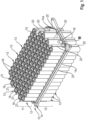
- FIG. 1 shows a perspective view of a preferred embodiment of assemblies of a battery module according to the invention, namely a plurality of battery cells 13 and a device 10 for cooling the battery cells 13.
- the arrangement of 1 may be housed in a module housing (not shown).
- the battery cells 13 are arranged in two battery cell planes 11, 12 arranged one above the other.
- a plurality of battery cells 13 are arranged in a first battery cell level 11, forming eight rows of battery cells 13 in the exemplary embodiment shown.
- a multiplicity of battery cells 13 are likewise arranged in the lower battery cell level 12 and likewise form eight rows of battery cells 13 .
- Fourteen battery cells 13 are arranged in each row of battery cells 13 . It should be noted that the number of battery cells 13 per row and the number of rows of battery cells 13 per battery cell level 11, 12 is purely exemplary.
- the device 10 for cooling the battery cells 13 has a first cooling plate 14 which is arranged between the first battery cell level 11 and the second battery cell level 12 and which, via its outer sides, is in thermal contact with the battery cells 13 of the first battery cell level 11 and in thermal contact with the battery cells 13 of the second battery cell level 12 is available. That's what it says in 1 the first cooling plate 14 is in thermal contact with an underside of the battery cells 13 of the first battery cell level 11 via a first outer side and with an upper side of the battery cells 13 of the second battery cell level 12 via a second outer side.
- Electrical contacts 16 of the battery cells 13 are formed on the top side of the battery cells 13 in the first battery cell level 11 and on the underside of the battery cells 13 in the second battery cell level 12 . Those sides of the respective battery cell 13 on which the electrical contacts 16 of the battery cells 13 are formed therefore face away from the first cooling plate 14 . The battery cells 13 accordingly rest against the first cooling plate 14 with the sides facing away from the electrical contacts 16 of the battery cells 13, specifically on the outer sides of the first cooling plate 14.
- the first cooling plate 14 can have a sandwich-like structure, preferably made up of three sub-plates 14a, 14b and 14c. It is possible that the first cooling plate 14 is also formed by only two sub-plates. Also, the first cooling plate 14 may be a monolithic assembly, such as made by 3D printing.
- the two outer partial plates 14a, 14b form the outer sides of the first cooling plate 14, via which the first cooling plate 14 is in thermal contact with the battery cells 13 of the two battery cell levels 11, 12 .
- the at least one middle partial plate 14b is sandwiched between the partial plates 14a, 14c and together with the partial plates 14a, 14c defines flow channels 17 of the first cooling plate 14 for the cooling medium.
- first cooling plate 14 When the first cooling plate 14 is formed from two partial plates, these partial plates form the outer sides of the first cooling plate 14, via which the first cooling plate 14 is in thermal contact with the battery cells 13 of the two battery cell levels 11, 12. These two partial plates then define the flow channels 17 of the first cooling plate 14 for the cooling medium.
- the device 10 for cooling the battery cells has a plurality of second cooling plates 15 2 can be removed, which shows the device 10 for cooling the battery cells 13 without the battery cells 13, in each battery cell level 11, 12 several, four in the embodiment shown, second cooling plates 15 are arranged.
- the second cooling plates 15, like the first cooling plate 14, have the cooling fluid flowing through them, with each of the second cooling plates 15 being in thermal contact with a plurality of battery cells of the respective battery cell level 11, 12, in such a way that each of the second cooling plates 15 is on each side thereof each with a row of battery cells 13 is in thermal contact.
- the device 10 also has a cooling fluid inlet 19 or cooling fluid inlet and a cooling fluid outlet 18 or cooling fluid outlet.
- Cooling fluid inlet 19 and cooling fluid outlet 18 are formed at different ends or sides of the first cooling plate 14 .
- Cooling fluid flows into the first cooling plate 14 , namely the flow channels 17 of the first cooling plate 14 , via the cooling fluid inlet 19 .
- a first part of this cooling fluid flowing into the first cooling plate 14 via the cooling fluid inlet 19 flows exclusively through the first cooling plate 14 in the direction of the opposite, second side of the first cooling plate 14, in order to escape on this opposite, second side of the first cooling plate 14 via the cooling fluid outlet 18 to flow out of the first cooling plate 14 .
- a second part of the cooling fluid flowing into the first cooling plate 14 via the cooling fluid inlet 19 flows on the first side of the first cooling plate 14 from the first cooling plate 14 into the second cooling plates 15, flows through the second cooling plates 15 and flows on the second, opposite side of the first Cooling plate 14 from the second cooling plates 15 back into the first cooling plate 14, in order to then flow out again on the second side of the first cooling plate 14 via the cooling fluid outlet 18 from the first cooling plate 14 and thus from the device 10 for cooling the battery cells 13.
- the second cooling plates 15 In the longitudinal direction, ie between the first side of the first cooling plate 14 and the opposite second side of the first cooling plate 14, the second cooling plates 15 have a corrugated course or a corrugated contour with elevations 15a and depressions 15b. This contour of alternating elevations 15a and depressions 15b is formed on both sides of the second cooling plates 15.
- the opposite ends of the second cooling plates 15 have tubes, namely inlet tubes 21 on the first side of the first cooling plate 14 and outlet tubes 20 on the opposite second side of the first cooling plate 14.
- the second part of the cooling fluid flowing into the first cooling plate 14 can flow from the first cooling plate 14 into the second cooling plates 15 via the inlet pipes 21 . After flowing through the second cooling plates 15 , this second part of the cooling fluid can exit via the outlet pipes 20 and flow back into the first cooling plate 14 in order to then be discharged via the cooling fluid outlet 18 .
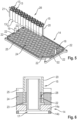
- FIG. 6 shows the detail VI of 1 in the area of an outlet pipe 20 of a second cooling plate 15.
- this outlet pipe 20 of the second cooling plate 15 shown is connected in a fluid-tight manner to a connecting piece 22 of the first cooling plate 14, according to FIG 6 an end of the outlet pipe 20 facing the first cooling plate 14 rests on a projection 23 of the connecting piece 22 running in the circumferential direction.
- the detail VI of 6 also applies to the opposite inlet pipes 21 of the second cooling plates 15.
- the respective connecting piece 22 is coupled on the flow side to the flow channels 17 of the first cooling plate 14 .
- the inlet pipes 21 of the second cooling plates 15 are fluid-tightly connected to the connection pieces 22 of the first cooling plate 14 for the inlet pipes 21 and the outlet pipes 20 of the second cooling plates 15 are connected to the connection pieces 22 of the first cooling plate 14 for the outlet pipes 20 via a heat-conducting potting material 24.
- this heat-conducting potting material 24 is also arranged in an annular gap 28 between the respective connecting piece 22 and the inlet pipe 21 or between the respective connecting piece 22 and the outlet pipe 20 .
- the second cooling plates 15 are therefore not welded to the connecting pieces 22 of the first cooling plate 14 in the area of their inlet pipes 21 and outlet pipes 20 , but are connected in a fluid-tight manner via the heat-conducting casting material 24 .
- each second cooling plate 15 The battery cells arranged in rows on each side of each second cooling plate 15 are also connected to the respective second cooling plate 15 via a heat-conducting potting material.
- This casting material preferably corresponds to the casting material 24 which is used for the fluid-tight connection of the inlet pipes 21 and the outlet pipes 20 of the second cooling plates 15 to the connecting pieces 22 of the first cooling plate 14 .
- there is a row of a plurality of battery cells 13 which are connected to the respective second cooling plate 15 via the heat-conducting potting material.
- the thermally conductive potting material is, in particular, a polyurethane-based potting material, in particular a two-component polyurethane-based adhesive. This is particularly thermally stable at a continuous service temperature between at least -40 °C and +130 °C.
- the heat-conducting potting material preferably the 2-component polyurethane-based adhesive, is resistant or stable to the cooling medium in such a way that the cooling medium does not impair the properties of the potting material.
- a 2-component adhesive which is available under the brand name "WEVOPUR" can be used as the 2-component adhesive based on polyurethane.
- the second cooling plates 15 between their inlet pipes 21 and outlet pipes 20 have a corrugated contour with the elevations 15a and the depressions 15b formed between the elevations 15a.
- a battery cell 13 is arranged in each depression 15b and protrudes in sections into the respective depression 15b.
- the depressions 15b on a first side of the respective second cooling plate 15 and thus the battery cells 13 arranged in the depressions 15b on the first side, which form a row of battery cells 13, are opposite the depressions 15b on the opposite second side of the respective second cooling plate 15 and thus offset in relation to the battery cells 13 arranged in the depressions 15b on the second side, which form a further row of battery cells 13, preferably in such a way that each battery cell 13 arranged on the second side of the respective second cooling plate 15 is in the middle between two battery cells 13 arranged on the first side of the respective second cooling plate 15 .
- the second cooling plates 15 are connected to the connecting pieces 22 of the first cooling plate 14 in a fluid-tight manner via their inlet pipes 21 and outlet pipes 20, namely via the heat-conducting casting material 24. 6 it can be seen that the connecting pieces 22 are coupled to the flow channels 17 of the first cooling plate 14 on the flow side in order to allow the cooling fluid to overflow between the first cooling plate 14 and the respective second cooling plate 15 in the area of the inlet pipes 21 and outlet pipes 20 of the second cooling plates 15 make possible.
- the first cooling plate 14, preferably outer sub-plates 14a, 14c thereof, has a peripheral edge 25, which serves to accommodate the heat-conducting potting material 24, in particular when the potting material 24 is not yet hardened and liquid during manufacture of the battery module.
- battery cells 13 and second cooling plates 15 are provided. From the second cooling plates 15 and the battery cells 13 subassemblies 26 are formed, wherein 3 such a pre-assembly assembly 26 from a second cooling plate 15 and a plurality of battery cells 13 shows.
- the procedure is such that the battery cells 13 arranged on both sides of the second cooling plate 15 are connected to the second cooling plate 15 via the heat-conducting potting material 24 with every second cooling plate 15 .
- the heat-conducting potting material 24 is applied to both sides of the respective second cooling plate 15, at least in the region of the depressions 15b thereof, with the battery cells 13 then being connected to the respective second cooling plate 15, specifically by the battery cells 13 being inserted into the depressions 15b can be used on both sides of the second cooling plate 15 and pressed, with the thermally conductive potting material 24 curing.
- An arrangement of a second cooling plate 15 and two rows of a plurality of battery cells 13 is arranged between the two tool halves 27a and 27b of the assembly tool 27, with a row of a plurality of battery cells 13 being arranged on each side of the respective second cooling plate 15.
- the arrangement of the second cooling plate 15 and the two rows of battery cells 13 is pressed using the tool halves 27a and 27b while the casting material 24 hardens, in order to form the preassembled assemblies 26 in this way.
- the second cooling plates 15 are connected to the first cooling plate 14 of the respective battery module in such a way that the inlet pipes 21 and the outlet pipes 20 of the second cooling plates 15 of the pre-assembly assemblies 26 are connected in a fluid-tight manner to the connecting piece 22 of the first cooling plate 14 via the heat-conducting potting material 24 .
- the potting material 24 is first applied to a first, upward-facing or upward-aligned outside of the first cooling plate 14 to the respective outside of the respective outer partial plate 14a, 14c, with the potting material that is still liquid over the edge 25 on the respective outside of the first cooling plate 14 is held in such a way that the same cannot flow down from the respective outside.
- the respective pre-assembly assemblies 26 are then connected to the first cooling plate 14 on this first outside, as explained above, providing the fluid-tight connection of the inlet pipes 21 and the outlet pipes 20 of the second cooling plates 15 of the pre-assembly assemblies 16 to the first cooling plate 14.
- the battery cells 13 of the respective pre-assembly assembly 26 are also connected to the first cooling plate 14 at the ends of the battery cells 13 facing the first cooling plate 14.
- the potting material 24 gets into the annular gaps 28 between the connecting pieces 22 of the first cooling plate 14 and the inlet pipes 21 and outlet pipes 20 of the pre-assembly assemblies 26 and thus the second cooling plates 15 of the pre-assembly assemblies 26, with this casting material 24 then hardening and thus the fluid-tight connection between the inlet pipes 21 and outlet pipes 20 of the second cooling plates 15 and the connection piece 22 of the first cooling plate 14 provides.
Abstract
Batteriemodul einer Traktionsbatterie eines Kraftfahrzeugs, mit mehreren in übereinander positionierten Batteriezellenebenen angeordneten Batteriezellen, und mit einer Vorrichtung zur Kühlung der Batteriezellen, die folgendes aufweist: Eine zwischen einer ersten Batteriezellenebene und einer zweiten Batteriezellenebene angeordnete erste Kühlplatte (14), die in thermischem Kontakt mit den Batteriezellen der ersten und zweiten Batteriezellenebene steht. Innerhalb der ersten und zweiten Batteriezellenebene angeordnete zweite Kühlplatten (15), die in thermischem Kontakt mit mehreren Batteriezellen (13) der jeweiligen Batteriezellenebene stehen. Die erste Kühlplatte (14) und die zweiten Kühlplatten (15) sind derart ausgebildet, dass ein erster Teil eines in die erste Kühlplatte einströmenden Kühlfluids die erste Kühlplatte durchströmt und aus der ersten Kühlplatte ausströmt, und dass ein zweiter Teil des in die erste Kühlplatte (14) einströmenden Kühlfluids von der ersten Kühlplatte (14) in die zweiten Kühlplatten (15) strömt, die zweiten Kühlplatten durchströmt von den zweiten Kühlplatten (15) in die erste Kühlplatte (14) strömt und aus der der ersten Kühlplatte ausströmt. Eintrittsrohre (21) der zweiten Kühlplatten, über welche der zweite Teil des Kühlfluids von der ersten Kühlplatte in die zweiten Kühlplatten strömt, und Austrittsrohre der zweiten Kühlplatten, über welche der zweite Teil des Kühlfluids von den zweiten Kühlplatten in die erste Kühlplatten strömt, sind mit Anschlussstutzen (22) der ersten Kühlplatte für die Eintrittsrohre (21) und Austrittsrohre (20) über ein wärmeleitendes Vergussmaterial (24) fluiddicht verbunden.Battery module of a traction battery of a motor vehicle, with a plurality of battery cells arranged in battery cell levels positioned one above the other, and with a device for cooling the battery cells, which has the following: A first cooling plate (14) arranged between a first battery cell level and a second battery cell level, which is in thermal contact with the Battery cells of the first and second battery cell level is. Second cooling plates (15) arranged within the first and second battery cell level, which are in thermal contact with a plurality of battery cells (13) of the respective battery cell level. The first cooling plate (14) and the second cooling plates (15) are designed in such a way that a first part of a cooling fluid flowing into the first cooling plate flows through the first cooling plate and out of the first cooling plate, and that a second part of the cooling fluid flowing into the first cooling plate ( 14) inflowing cooling fluid flows from the first cooling plate (14) into the second cooling plates (15), flows through the second cooling plates, flows from the second cooling plates (15) into the first cooling plate (14) and flows out of the first cooling plate. Inlet pipes (21) of the second cooling plates, through which the second part of the cooling fluid flows from the first cooling plate into the second cooling plates, and outlet pipes of the second cooling plates, through which the second part of the cooling fluid flows from the second cooling plates into the first cooling plates, are Connecting piece (22) of the first cooling plate for the inlet pipes (21) and outlet pipes (20) via a heat-conducting potting material (24) connected in a fluid-tight manner.
Description
Die Erfindung betrifft ein Batteriemodul einer Traktionsbatterie eines Kraftfahrzeugs. Ferner betrifft die Erfindung ein Verfahren zum Herstellen eines solchen Batteriemoduls.The invention relates to a battery module for a traction battery in a motor vehicle. Furthermore, the invention relates to a method for producing such a battery module.
In Kraftfahrzeugen, wie zum Beispiel in Hybridfahrzeugen oder auch Elektrofahrzeugen, sind Traktionsbatterien verbaut, die der Speicherung elektrischer Energie dienen, um dieselbe einer elektrischen Maschine bereitzustellen. Traktionsbatterien verfügen über mehrere Batteriemodule, die untereinander elektrisch verschaltet sind. Jedes Batteriemodul verfügt über mehrere Batteriezellen, die auch untereinander elektrisch verschaltet sind. Im Betrieb unterliegen die Batteriezellen, zum Beispiel infolge von chemischen Reaktionen innerhalb der Batteriezellen, einer Erwärmung. Um eine Beschädigung der Batteriemodule und damit der Traktionsbatterie infolge von einer Überhitzung der Batteriezellen zu vermeiden, muss durch Kühlung der Batteriezellen Wärme von der Traktionsbatterie abgeführt werden. Es ist bereits bekannt, die Batteriezellen einer Traktionsbatterie zu kühlen. Hierzu verfügt ein Batteriemodul einer Traktionsbatterie einer Vorrichtung zur Kühlung der Batteriezellen.In motor vehicles, such as hybrid vehicles or electric vehicles, traction batteries are installed, which are used to store electrical energy in order to provide the same to an electrical machine. Traction batteries have several battery modules that are electrically interconnected. Each battery module has several battery cells, which are also electrically interconnected. During operation, the battery cells are subject to heating, for example as a result of chemical reactions within the battery cells. In order to avoid damage to the battery modules and thus to the traction battery as a result of overheating of the battery cells, heat must be dissipated from the traction battery by cooling the battery cells. It is already known to cool the battery cells of a traction battery. For this purpose, a battery module of a traction battery has a device for cooling the battery cells.
Aus
Aus der
Es besteht Bedarf an einem Batteriemodul einer Traktionsbatterie eines Kraftfahrzeugs, die einfach herstellbar ist. Aufgabe der Erfindung ist es, ein Batteriemodul einer Traktionsbatterie eines Kraftfahrzeugs und Verfahren zum Herstellen eines solchen Batteriemodul einer Traktionsbatterie zu schaffen.There is a need for a battery module of a motor vehicle traction battery that is easy to manufacture. The object of the invention is to create a battery module for a traction battery in a motor vehicle and a method for producing such a battery module for a traction battery.
Diese Aufgabe wird durch ein Batteriemodul einer Traktionsbatterie eines Kraftfahrzeugs nach Anspruch 1. Das Batteriemodul weist mehrere in mindestens zwei übereinander positionierten Batteriezellenebenen angeordnete Batteriezellen auf. Das Batteriemodul weist ferner einer Vorrichtung zur Kühlung der Batteriezellen auf. Die Vorrichtung zur Kühlung der Batteriezellen weist folgende Baugruppen auf: Eine zwischen einer ersten Batteriezellenebene und einer zweiten Batteriezellenebene angeordneten erste Kühlplatte, die in thermischem Kontakt mit den Batteriezellen der ersten Batteriezellenebene und in thermischem Kontakt mit den Batteriezellen der zweiten Batteriezellenebene steht. Innerhalb der ersten Batteriezellenebene angeordnete zweite Kühlplatten und innerhalb der zweiten Batteriezellenebene angeordnete weitere zweite Kühlplatten, die in thermischem Kontakt mit mehreren Batteriezellen der jeweiligen Batteriezellenebene stehen. Die erste Kühlplatte und die zweiten Kühlplatten sind derart ausgebildet, dass ein erster Teil eines in die erste Kühlplatte einströmenden Kühlfluids die erste Kühlplatte durchströmt und aus der ersten Kühlplatte ausströmt, und dass ein zweiter Teil des in die erste Kühlplatte einströmenden Kühlfluids von der ersten Kühlplatte in die zweiten Kühlplatten strömt, die zweiten Kühlplatten durchströmt von den zweiten Kühlplatten in die erste Kühlplatte strömt und aus der der ersten Kühlplatte ausströmt. Eintrittsrohre der zweiten Kühlplatten, über welche der zweite Teil des Kühlfluids von der ersten Kühlplatte in die zweiten Kühlplatten strömt, und Austrittsrohre der zweiten Kühlplatten, über welche anschließend der zweite Teil des Kühlfluids von den zweiten Kühlplatten in die erste Kühlplatte strömt, sind mit Anschlussstutzen der ersten Kühlplatte für die Eintrittsrohre und Austrittsrohre über ein wärmeleitendes Vergussmaterial fluiddicht verbunden.This object is achieved by a battery module of a traction battery of a motor vehicle according to claim 1. The battery module has a plurality of battery cells arranged in at least two battery cell planes positioned one above the other. The battery module also has a device for cooling the battery cells. The device for cooling the battery cells has the following assemblies: A first cooling plate arranged between a first battery cell level and a second battery cell level, which is in thermal contact with the battery cells of the first battery cell level and in thermal contact with the battery cells of the second battery cell level. Second cooling plates arranged within the first battery cell level and further second cooling plates arranged within the second battery cell level, which are in thermal contact with a plurality of battery cells of the respective battery cell level. The first cooling plate and the second cooling plates are designed in such a way that a first part of a cooling fluid flowing into the first cooling plate flows through the first cooling plate and out of the first cooling plate, and that a second part of the cooling fluid flowing into the first cooling plate flows from the first cooling plate into flows through the second cooling plates, flows through the second cooling plates, flows from the second cooling plates into the first cooling plate and flows out of the first cooling plate. Inlet pipes of the second cooling plates, through which the second part of the cooling fluid flows from the first cooling plate into the second cooling plates, and outlet pipes of the second cooling plates, through which the second part of the cooling fluid then flows from the second cooling plates into the first cooling plate, are equipped with connection pieces of the first cooling plate for the inlet pipes and outlet pipes fluid-tightly connected via a thermally conductive potting material.
Das erfindungsgemäße Batteriemodul verfügt über die mehreren Batteriezellen sowie über die Vorrichtung zur Kühlung der Batteriezellen, wobei die Vorrichtung zur Kühlung der Batteriezellen die erste Kühlplatte und die mehreren zweiten Kühlplatten aufweist. Die Batteriezellen sind in zwei übereinander positionierten Batteriezellenebenen angeordnet, ebenso die zweiten Kühlplatten, wobei die erste Kühlplatte die beiden Batteriezellenebenen trennt.The battery module according to the invention has the multiple battery cells and the device for cooling the battery cells, the device for cooling the battery cells having the first cooling plate and the multiple second cooling plates. The battery cells are arranged in two battery cell levels positioned one above the other, as are the second cooling plates, with the first cooling plate separating the two battery cell levels.
Der zweite Teil des in die erste Kühlplatte eintretenden Kühlmediums strömt von der ersten Kühlplatte in die zweiten Kühlplatten, durchströmt die zweiten Kühlplatten und tritt danach wieder in die erste Kühlplatte ein. Hierzu sind Eintrittsrohre der zweiten Kühlplatten und Austrittsrohre der zweiten Kühlplatten mit entsprechenden Anschlussstutzen der ersten Kühlplatte fluiddicht verbunden, und zwar über ein wärmeleitendes Vergussmaterial.The second part of the cooling medium entering the first cooling plate flows from the first cooling plate into the second cooling plates, flows through the second cooling plates and then re-enters the first cooling plate. For this purpose, inlet pipes of the second cooling plates and outlet pipes of the second cooling plates are connected in a fluid-tight manner to corresponding connection pieces of the first cooling plate, specifically via a heat-conducting potting material.
Die zweiten Kühlplatten sind demnach nicht mit den ersten Kühlplatten verschweißt, um die fluiddichte Verbindung zwischen den zweiten Kühlplatten und den ersten Kühlplatten auszubilden, vielmehr erfolgt die Verbindung der zweiten Kühlplatten mit der ersten Kühlplatte über das wärmeleitende Vergussmaterial. Hierdurch lässt sich die Kühlvorrichtung des Batteriemoduls und damit letztendlich das Batteriemodul mit geringem Aufwand einfach herstellen.The second cooling plates are therefore not welded to the first cooling plates in order to form the fluid-tight connection between the second cooling plates and the first cooling plates; instead, the second cooling plates are connected to the first cooling plate via the heat-conducting potting material. As a result, the cooling device of the battery module and thus ultimately the battery module can be easily produced with little effort.
Vorzugsweise ist an jeder Seite jeder zweiten Kühlplatte jeweils eine Reihe aus jeweils mehreren Batteriezellen angeordnet, die mit der jeweiligen zweiten Kühlplatte über wärmeleitendes Vergussmaterial verbunden sind. Auch dies dient der einfachen Herstellung des Batteriemoduls. Aus zweiten Kühlplatten und Batteriezellen, die mit den zweiten Kühlplatten über das wärmeleitende Vergussmaterial verbunden sind, können Vormontagebaugruppen ausgebildet werden, die dann mit der ersten Kühlplatte verbunden werden.A row of a plurality of battery cells is preferably arranged on each side of each second cooling plate, which are connected to the respective second cooling plate via heat-conducting potting material. This also serves to simplify the production of the battery module. Preassembled assemblies can be formed from second cooling plates and battery cells, which are connected to the second cooling plates via the heat-conducting potting material, and are then connected to the first cooling plate.
Vorzugsweise ist das wärmeleitende Vergussmaterial ein Polyurethan-Vergussmaterial. Vorzugsweise ist Polyurethan-Vergussmaterial ein 2-Komponenten-Klebstoff, der insbesondere bei einer Dauergebrauchstemperatur zumindest zwischen -40°C und +130°C thermisch stabil ist.Preferably, the thermally conductive potting material is a polyurethane potting material. Polyurethane potting material is preferably a 2-component adhesive that is thermally stable, particularly at a continuous use temperature of at least between -40°C and +130°C.
Die Verwendung eines 2-Komponenten-Klebstoffs vorzugsweise auf Polyurethanbasis als Vergussmaterial ist besonders bevorzugt. Ein solcher 2-Komponenten-Klebstoff ist zumindest bei einer Dauergebrauchstemperatur zwischen -40 °C und +130 °C, abhängig vom 2-Komponenten-Klebstoff auch bis zu +180 °C, thermisch stabil. So besteht keine Gefahr, dass sich die Verbindung zwischen den zweiten Kühlplatten und der ersten Kühlplatte sowie die Verbindung der Batteriezellen mit den zweiten Kühlplatten im Betrieb des Kraftfahrzeugs löst. Ferner ist die Verarbeitung eines solchen 2-Komponenten-Klebstoffs einfach, wodurch die Herstellung des Batteriemoduls vereinfacht wird.The use of a 2-component adhesive, preferably based on polyurethane, as the casting material is particularly preferred. Such a 2-component adhesive is thermally stable at least at a continuous service temperature between -40 °C and +130 °C, depending on the 2-component adhesive also up to +180 °C. There is thus no risk of the connection between the second cooling plates and the first cooling plate and the connection of the battery cells with the second cooling plates becoming detached during operation of the motor vehicle. Furthermore, the processing of such a 2-component adhesive is simple, which simplifies the production of the battery module.
Vorzugsweise weist die erste Kühlplatte einen Aufbau aus mehreren Teilplatten auf, wobei äußere Teilplatten Außenseiten der ersten Kühlplatte bilden und vorzugsweise zusammen mit einer vorzugsweise sandwichartig zwischen den äußeren Teilplatten angeordneten mittleren Teilplatte Strömungskanäle der ersten Kühlplatte für das Kühlmedium bilden.The first cooling plate preferably has a structure of several partial plates, outer partial plates forming outer sides of the first cooling plate and preferably forming flow channels of the first cooling plate for the cooling medium together with a middle partial plate preferably sandwiched between the outer partial plates.
Die erste Kühlplatte, vorzugsweise die äußeren Teilplatten derselben, weisen vorzugweise an den Außenseiten der ersten Kühlplatte einen umlaufenden Rand auf, welcher der Aufnahme des wärmeleitenden Vergussmaterials dient. Über die Außenseiten der ersten Kühlplatte steht dieselben mit den Batteriezellen in Kontakt. Der umlaufende Rand an den Außenseiten der ersten Kühlplatte stellt sicher, dass dann, wenn der 2-Komponenten-Klebstoff, der als Vergussmaterial dient, noch nicht ausgehärtet und demnach flüssig ist, auf der Außenseite der ersten Kühlplatte gehalten werden kann. So kann das Batteriemodul einfach hergestellt werden.The first cooling plate, preferably the outer partial plates of the same, preferably have a peripheral edge on the outer sides of the first cooling plate, which serves to accommodate the heat-conducting potting material. The outside of the first cooling plate is in contact with the battery cells. The peripheral edge on the outside of the first cooling plate ensures that when the 2-component adhesive that serves as the casting material has not yet hardened and is therefore liquid, it can be held on the outside of the first cooling plate. Thus, the battery module can be easily manufactured.
Das erfindungsgemäße Verfahren zum Herstellen eines Batteriemoduls einer Traktionsbatterie ist in Anspruch 11 definiert. Das Verfahren umfasst zumindest die folgenden Schritte: Bereitstellen der Batteriezellen. Bereitstellen der zweiten Kühlplatten. Ausbilden von Vormontagebaugruppen aus jeweils einer zweiten Kühlplatte und mehreren zu beiden Seiten der zweiten Kühlplatte angeordneten Batteriezellen. Bereitstellen der ersten Kühlplatte. Verbinden der Vormontagebaugruppen mit der ersten Kühlplatte, derart, dass die Eintrittsrohre der zweiten Kühlplatten und die Austrittsrohre der zweiten Kühlplatten mit Anschlussstutzen der ersten Kühlplatte für die Eintrittsrohre und Austrittsrohre der zweiten Kühlplatten über das wärmeleitende Vergussmaterial fluiddicht verbunden sind. Das erfindungsgemäße Verfahren erlaubt eine einfache Herstellung des erfindungsgemäßen Batteriemoduls.The method according to the invention for producing a battery module of a traction battery is defined in
Vorzugsweise werden beim Ausbilden der Vormontagebaugruppen mit jeder zweiten Kühlplatte die zu beiden Seiten der zweiten Kühlplatte angeordneten Batteriezellen mit der zweiten Kühlplatte über das wärmeleitenden Vergussmaterial verbunden. Hierzu wird auf beiden Seiten der jeweiligen zweiten Kühlplatte das wärmeleitende Vergussmaterial aufgetragen und dann werden die Batteriezellen mit der jeweiligen zweiten Kühlplatte unter Aushärten des Vergussmaterials verpresst. Dies erlaubt eine besonders einfache Herstellung der Vormontagebaugruppen des Batteriemoduls.The battery cells arranged on both sides of the second cooling plate are preferably connected to the second cooling plate via the heat-conducting potting material when forming the preassembled assemblies with every second cooling plate. For this purpose, the heat-conducting potting material is applied to both sides of the respective second cooling plate and then the battery cells are pressed with the respective second cooling plate while the potting material hardens. This allows a particularly simple production of the pre-assembled assemblies of the battery module.
Vorzugsweise wird beim Verbinden der Vormontagebaugruppen mit der ersten Kühlplatte auf eine erste Außenseite der ersten Kühlplatte das wärmeleitende Vergussmaterial aufgetragen, wobei anschießend an dieser ersten Außenseite die jeweiligen Vormontagebaugruppen mit der ersten Kühlplatte verbunden werden. Anschließend wird auf eine gegenüberliegende zweite Außenseite der ersten Kühlplatte das wärmeleitende Vergussmaterial aufgetragen, wobei anschießend an dieser zweiten Außenseite die jeweiligen Vormontagebaugruppen mit der ersten Kühlplatte verbunden werden. Hierbei gelangt das Vergussmaterial in Ringspalte zwischen den Anschlussstutzen der ersten Kühlplatte und den Eintrittsrohren und Austrittsrohren der zweiten Kühlplatten und härtet anschließend aus. Dies erlaubt eine besonders einfache Herstellung des Batteriemoduls.When connecting the pre-assembly assemblies to the first cooling plate, the heat-conducting potting material is preferably applied to a first outer side of the first cooling plate, with the respective pre-assembly assemblies then being connected to the first cooling plate on this first outer side. The heat-conducting potting material is then applied to an opposite, second outside of the first cooling plate, with the respective pre-assembly assemblies then being connected to the first cooling plate on this second outside. Here, the casting material gets into annular gaps between the connection piece of the first cooling plate and the inlet pipes and outlet pipes of the second cooling plates and then hardens. This allows a particularly simple production of the battery module.
Bevorzugte Weiterbildungen der Erfindung ergeben sich aus den Unteransprüchen und der nachfolgenden Beschreibung. Ausführungsbeispiele der Erfindung werden, ohne hierauf beschränkt zu sein, an Hand der Zeichnung näher erläutert. Dabei zeigt:
- Fig. 1
- eine perspektivische Ansicht eines Batteriemoduls einer Traktionsbatterie eines Kraftfahrzeugs,
- Fig. 2
- eine perspektivische Ansicht einer Vorrichtung zur Kühlung der Batteriezellen des Batteriemoduls der
Fig. 1 , - Fig. 3
- eine perspektivische Ansicht einer Vormontagebaugruppe des Batteriemoduls der
Fig. 1 , - Fig. 4
- die Vormontagebaugruppe der
Fig. 3 zusammen mit einem Montagewerkzeug, - Fig. 5
- die Vormontagebaugruppe der
Fig. 3 zusammen mit einer ersten Kühlplatte der Vorrichtung derFig. 2 , - Fig. 6
- einen Querschnitt durch das Detail VI des Batteriemoduls der
Fig. 1 .
- 1
- a perspective view of a battery module of a traction battery of a motor vehicle,
- 2
- a perspective view of a device for cooling the battery cells of the battery module
1 , - 3
- a perspective view of a subassembly of the battery module
1 , - 4
- the pre-assembly assembly
3 together with an assembly tool, - figure 5
- the pre-assembly assembly
3 together with a first cooling plate of the device2 , - 6
- a cross section through the detail VI of the battery module
1 .
Die Batteriezellen 13 sind in zwei übereinander angeordneten Batteriezellenebenen 11, 12 angeordnet. So sind in einer ersten Batteriezellenebene 11 mehrere Batteriezellen 13 angeordnet, die im gezeigten Ausführungsbeispiel acht Reihen von Batteriezellen 13 bilden. In der unteren Batteriezellenebene 12 sind ebenfalls eine Vielzahl von Batteriezellen 13 angeordnet, die ebenfalls acht Reihen von Batteriezellen 13 ausbilden. In jeder Reihe aus Batteriezellen 13 sind jeweils vierzehn Batteriezellen 13 angeordnet. Es sei darauf hingewiesen, dass die Anzahl der Batteriezellen 13 je Reihe und die Anzahl der Reihen an Batteriezellen 13 je Batteriezellenebene 11, 12 rein exemplarischer Natur ist.The
Die Vorrichtung 10 zur Kühlung der Batteriezellen 13 verfügt über eine zwischen der ersten Batteriezellenebene 11 und der zweiten Batteriezellenebene 12 angeordnete erste Kühlplatte 14, die über ihre Außenseiten im thermischen Kontakt mit den Batteriezellen 13 der ersten Batteriezellenebene 11 und im thermischen Kontakt mit den Batteriezellen 13 der zweiten Batteriezellenebene 12 steht. So steht in
In der ersten Batteriezellenebene 11 sind an der Oberseite der Batteriezellen 13 und in der zweiten Batteriezellenebene 12 an der Unterseite der Batteriezellen 13 elektrische Kontakte 16 der Batteriezellen 13 ausgebildet. Diejenigen Seiten der jeweiligen Batteriezelle 13, an welchen die elektrischen Kontakte 16 der Batteriezellen 13 ausgebildet sind, sind also von der ersten Kühlplatte 14 abgewandt. Die Batteriezellen 13 liegen demnach mit den von den elektrischen Kontakten 16 der Batteriezellen 13 abgewandten Seiten an der ersten Kühlplatte 14 an, und zwar an den Außenseiten der ersten Kühlplatte 14.
Die erste Kühlplatte 14 ist von einem Kühlfluid durchströmt. Die erste Kühlplatte 14 kann über einen sandwichartigen Aufbau aus vorzugsweise drei Teilplatten 14a, 14b und 14c verfügen. Es ist möglich, dass die erste Kühlplatte 14 auch von lediglich zwei Teilplatten gebildet ist. Auch kann die erste Kühlplatte 14 eine monolithische Baugruppe sein, die z.B. durch 3D Drucken hergestellt ist.A cooling fluid flows through the
Dann, wenn die erste Kühlplatte 14 aus mehr als zwei Teilplatten gebildet ist, bilden die beiden äußeren Teilplatten 14a, 14b die Außenseiten der ersten Kühlplatte 14, über welche die erste Kühlplatte 14 mit den Batteriezellen 13 der beiden Batteriezellenebenen 11, 12 im thermischen Kontakt steht. Die mindestens eine mittlere Teilplatte 14b ist sandwichartig zwischen den Teilplatten 14a, 14c angeordnet und definiert zusammen mit den Teilplatten 14a, 14c Strömungskanäle 17 der ersten Kühlplatte 14 für das Kühlmedium.When the
Dann, wenn die erste Kühlplatte 14 aus zwei Teilplatten gebildet ist, bilden diese Teilplatten die Außenseiten der ersten Kühlplatte 14, über welche die erste Kühlplatte 14 mit den Batteriezellen 13 der beiden Batteriezellenebenen 11, 12 im thermischen Kontakt steht. Diese beiden Teilplatten definieren dann die Strömungskanäle 17 der ersten Kühlplatte 14 für das Kühlmedium.When the
Die Vorrichtung 10 zur Kühlung der Batteriezellen verfügt zusätzlich zu der ersten Kühlplatte 14 über mehrere zweite Kühlplatten 15. So sind, wie am besten
Die zweiten Kühlplatten 15 sind ebenso wie die erste Kühlplatte 14 von dem Kühlfluid durchströmt, wobei jede der zweiten Kühlplatten 15 im thermischen Kontakt mit mehreren Batteriezellen der jeweiligen Batteriezellenebene 11, 12 steht, und zwar derart, dass jede der zweiten Kühlplatten 15 auf jeder Seite derselben mit jeweils einer Reihe aus Batteriezellen 13 im thermischen Kontakt steht.The
Die Vorrichtung 10 verfügt ferner über einen Kühlfluideinlass 19 bzw. Kühlfluidzulauf und einen Kühlfluidauslass 18 bzw. Kühlfluidablauf.The
In
Über den Kühlfluideinlass 19 strömt Kühlfluid in die erste Kühlplatte 14, nämlich die Strömungskanäle 17 der ersten Kühlplatte 14 ein. Ein erster Teil dieses über den Kühlfluideinlass 19 in die erste Kühlplatte 14 einströmenden Kühlfluids strömt ausschließlich durch die erste Kühlplatte 14 hindurch in Richtung auf die gegenüberliegende zweite Seite der ersten Kühlplatte 14, um an dieser gegenüberliegenden zweiten Seite der ersten Kühlplatte 14 über den Kühlfluidauslass 18 aus der ersten Kühlplatte 14 herauszuströmen.Cooling fluid flows into the
Ein zweiter Teil des über den Kühlfluideinlass 19 in die erste Kühlplatte 14 einströmenden Kühlfluids strömt an der ersten Seite der ersten Kühlplatte 14 von der ersten Kühlplatte 14 in die zweiten Kühlplatten 15, durchströmt die zweiten Kühlplatten 15 und strömt an der zweiten, gegenüberliegenden Seite der ersten Kühlplatte 14 von den zweiten Kühlplatten 15 zurück in die erste Kühlplatte 14, um dann wiederum an der zweiten Seite der ersten Kühlplatte 14 über den Kühlfluidauslass 18 aus der ersten Kühlplatte 14 und damit aus der Vorrichtung 10 zur Kühlung der Batteriezellen 13 herauszuströmen.A second part of the cooling fluid flowing into the
Die zweiten Kühlplatten 15 verfügen in Längsrichtung, also zwischen der ersten Seite der ersten Kühlplatte 14 und der gegenüberliegenden zweiten Seite der ersten Kühlplatte 14 über einen gewellten Verlauf bzw. einen Wellenkontur mit Erhebungen 15a und Vertiefungen 15b. Diese Kontur aus sich abwechselnden Erhebungen 15a und Vertiefungen 15b ist an beiden Seiten der zweiten Kühlplatten 15 ausgebildet.In the longitudinal direction, ie between the first side of the
An den sich gegenüberliegenden Enden der zweiten Kühlplatten 15 verfügen dieselben über Rohre, nämlich an der ersten Seite der ersten Kühlplatte 14 über Eintrittsrohre 21 und an der gegenüberliegenden zweiten Seite der ersten Kühlplatte 14 über Austrittsrohre 20.The opposite ends of the
Über die Eintrittsrohre 21 kann der zweite Teil des in die erste Kühlplatte 14 einströmenden Kühlfluids von der ersten Kühlplatte 14 in die zweiten Kühlplatten 15 überströmen. Über die Austrittsrohre 20 kann dieser zweite Teil des Kühlfluids nach dem Durchströmen der zweiten Kühlplatten 15 aus denselben austreten und zurück in die erste Kühlplatte 14 strömen, um im Anschluss über den Kühlfluidauslass 18 abgeführt zu werden.The second part of the cooling fluid flowing into the
Die Eintrittsrohre 21 der zweiten Kühlplatten 15 sind mit den Anschlussstutzen 22 der ersten Kühlplatte 14 für die Eintrittsrohre 21 und die Austrittsrohre 20 der zweiten Kühlplatten 15 sind mit den Anschlussstutzen 22 der ersten Kühlplatte 14 für die Austrittsrohre 20 über ein wärmeleitendes Vergussmaterial 24 fluiddicht verbunden.The
Gemäß
Die zweiten Kühlplatten 15 sind demnach im Bereich ihrer Eintrittsrohre 21 und Austrittsrohre 20 mit den Anschlussstutzen 22 der ersten Kühlplatte 14 nicht verschweißt, sondern über das wärmeleitende Vergussmaterial 24 fluiddicht verbunden.The
Die an jeder Seite jeder zweiten Kühlplatte 15 in Reihen angeordneten Batteriezellen sind mit der jeweiligen zweiten Kühlplatte 15 ebenfalls über ein wärmeleitende Vergussmaterial verbunden. Dieses Vergussmaterial entspricht vorzugsweise dem Vergussmaterial 24, welches der fluiddichten Verbindung der Eintrittsrohre 21 und der Austrittsrohre 20 der zweiten Kühlplatten 15 mit den Anschlussstutzen 22 der ersten Kühlplatte 14 dient. So ist an jeder Seite jeder zweiten Kühlplatte 15 jeweils eine Reihe aus jeweils mehreren Batteriezellen 13 angeordnet, die mit der jeweiligen zweiten Kühlplatte 15 über das wärmeleitende Vergussmaterial verbunden sind.The battery cells arranged in rows on each side of each
Bei dem wärmeleitenden Vergussmaterial handelt es sich insbesondere um ein Vergussmaterial auf Polyurethanbasis, insbesondere um einen 2-Komponenten-Klebstoff auf Polyurethanbasis. Dieser ist insbesondere bei einer Dauergebrauchstemperatur zwischen mindestens -40 °C und +130 °C thermisch stabil.The thermally conductive potting material is, in particular, a polyurethane-based potting material, in particular a two-component polyurethane-based adhesive. This is particularly thermally stable at a continuous service temperature between at least -40 °C and +130 °C.
Ferner ist das wärmeleitende Vergussmaterial, vorzugsweise der 2-Komponenten-Klebstoff auf Polyurethanbasis, resistent bzw. stabil gegenüber dem Kühlmedium derart, dass das Kühlmedium die Eigenschaften des Vergussmaterials nicht beeinträchtigt.Furthermore, the heat-conducting potting material, preferably the 2-component polyurethane-based adhesive, is resistant or stable to the cooling medium in such a way that the cooling medium does not impair the properties of the potting material.
Als 2-Komponenten-Klebstoff auf Polyurethanbasis kann insbesondere ein 2-Komponenten-Klebstoff genutzt werden, der unter dem Markennamen "WEVOPUR" erhältlich ist.In particular, a 2-component adhesive which is available under the brand name "WEVOPUR" can be used as the 2-component adhesive based on polyurethane.
Wie oben bereits ausgeführt, verfügen die zweiten Kühlplatten 15 zwischen ihren Eintrittsrohren 21 und Austrittsrohren 20 über eine gewellte Kontur mit den Erhebungen 15a und den zwischen den Erhebungen 15a ausgebildeten Vertiefungen 15b. In jeder Vertiefung 15b ist eine Batteriezelle 13 angeordnet, die abschnittsweise in die jeweilige Vertiefung 15b hineinragt. Dabei sind die Vertiefungen 15b auf einer ersten Seite der jeweiligen zweiten Kühlplatte 15 und damit die in den Vertiefungen 15b an der ersten Seite angeordneten Batteriezellen 13, die eine Reihe aus Batteriezellen 13 bilden, gegenüber den Vertiefungen 15b auf der gegenüberliegenden zweiten Seite der jeweiligen zweiten Kühlplatte 15 und damit gegenüber den in den Vertiefungen 15b an der zweiten Seite angeordneten Batteriezellen 13, die eine weitere Reihe aus Batteriezellen 13 bilden, versetzt, vorzugsweise derart, dass jede an der zweiten Seite der jeweiligen zweiten Kühlplatte 15 angeordnete Batteriezelle 13 in der Mitte zwischen zwei an der ersten Seite der jeweiligen zweiten Kühlplatte 15 angeordneten Batteriezellen 13 positioniert ist.As already explained above, the
Wie ebenfalls oben bereits ausgeführt, sind die zweiten Kühlplatten 15 über ihre Eintrittsrohre 21 und Austrittsrohre 20 mit den Anschlussstutzen 22 der ersten Kühlplatte 14 fluiddicht verbunden, nämlich über das wärmeleitende Vergussmaterial 24.
Die erste Kühlplatte 14, vorzugsweise äußere Teilplatten 14a, 14c derselben, verfügt über einen umlaufenden Rand 25, welcher der Aufnahme des wärmeleitenden Vergussmaterials 24 dient, und zwar insbesondere im noch nicht ausgehärteten, flüssigen Zustand des Vergussmaterials 24 während der Herstellung des Batteriemoduls.The
Die in
Zunächst werden Batteriezellen 13 und zweite Kühlplatten 15 bereitgestellt. Aus den zweiten Kühlplatten 15 und den Batteriezellen 13 werden Vormontagebaugruppen 26 ausgebildet, wobei
Beim Ausbilden der Vormontagebaugruppen 26 wird so vorgegangen, dass mit jeder zweiten Kühlplatte 15 die zu beiden Seiten der zweiten Kühlplatte 15 angeordneten Batteriezellen 13 mit der zweiten Kühlplatte 15 über das wärmeleitende Vergussmaterial 24 verbunden werden.When forming the
Hierzu wird auf beiden Seiten der jeweiligen zweiten Kühlplatte 15, zumindest im Bereich der Vertiefungen 15b derselben, das wärmeleitende Vergussmaterial 24 aufgetragen, wobei dann die Batteriezellen 13 mit der jeweiligen zweiten Kühlplatte 15 verbunden werden, und zwar dadurch, dass die Batteriezellen 13 in die Vertiefungen 15b an den beiden Seiten der zweiten Kühlplatte 15 eingesetzt werden und verpresst werden, und zwar unter Aushärten des wärmeleitenden Vergussmaterials 24.For this purpose, the heat-conducting
Dies erfolgt vorzugsweise in dem in
Nach dem Ausbilden der Vormontagebaugruppen 26, also nach dem Verbinden von Batteriezellen 13 mit den zweiten Kühlplatten 15, werden die zweiten Kühlplatten 15 mit der ersten Kühlplatte 14 des jeweiligen Batteriemoduls verbunden, und zwar derart, dass die Eintrittsrohre 21 und die Austrittsrohre 20 der zweiten Kühlplatten 15 der Vormontagebaugruppen 26 mit den Anschlussstutzen 22 der ersten Kühlplatte 14 über das wärmeleitende Vergussmaterial 24 fluiddicht verbunden werden.After the
Hierzu wird zunächst das Vergussmaterial 24 an einer ersten, nach oben weisenden oder nach oben ausgerichteten Außenseite der ersten Kühlplatte 14 auf die jeweilige Außenseite der jeweiligen äußeren Teilplatte 14a, 14c aufgetragen, wobei hierbei das noch flüssige Vergussmaterial über den Rand 25 auf der jeweiligen Außenseite der ersten Kühlplatte 14 derart gehalten wird, dass dasselbe nicht von der jeweiligen Außenseite herunterfließen kann.For this purpose, the potting
Anschließend werden an dieser ersten Außenseite die jeweiligen Vormontagebaugruppen 26 mit der ersten Kühlplatte 14 verbunden, und zwar wie oben ausgeführt, unter Bereitstellung der fluiddichten Verbindung der Eintrittsrohre 21 und der Austrittsrohre 20 der zweiten Kühlplatten 15 der Vormontagebaugruppen 16 mit der ersten Kühlplatte 14.The respective
Hierbei erfolgt auch eine Verbindung der Batteriezellen 13 der jeweiligen Vormontagebaugruppe 26 mit der ersten Kühlplatte 14 an den der ersten Kühlplatte 14 zugewandten Enden der Batteriezellen 13.In this case, the
Anschließend wird die bis dahin herstellte Anordnung gedreht und auf die gegenüberliegende zweite, nunmehr nach oben weisende oder nach oben ausgerichtete Außenseite der ersten Kühlplatte 14 bzw. die gegenüberliegende äußere Teilplatte 14c, 14a der ersten Kühlplatte 14 wiederum das wärmeleitende Vergussmaterial 24 aufgetragen und anschließend werden an dieser zweiten Außenseite die jeweiligen Vormontagebaugruppen 26 mit der ersten Kühlplatte 14 verbunden.The arrangement produced up to that point is then rotated and the heat-conducting
Wie oben ausgeführt, gelangt hierbei das Vergussmaterial 24 in die Ringspalte 28 zwischen den Anschlussstutzen 22 der ersten Kühlplatte 14 und den Eintrittsrohren 21 sowie Austrittsrohren 20 der Vormontagbaugruppen 26 und damit der zweiten Kühlplatten 15 der Vormontagebaugruppen 26, wobei dieses Vergussmaterial 24 anschließend aushärtet und so die fluiddichte Verbindung zwischen den Eintrittsrohren 21 und Austrittsrohren 20 der zweiten Kühlplatten 15 und den Anschlussstutzen 22 der ersten Kühlplatte 14 bereitstellt.As explained above, the potting
Claims (16)
Applications Claiming Priority (1)
| Application Number | Priority Date | Filing Date | Title |
|---|---|---|---|
| DE102021125355.1A DE102021125355A1 (en) | 2021-09-30 | 2021-09-30 | Battery module of a traction battery of a motor vehicle and method for producing the same |
Publications (1)
| Publication Number | Publication Date |
|---|---|
| EP4160788A1 true EP4160788A1 (en) | 2023-04-05 |
Family
ID=83228849
Family Applications (1)
| Application Number | Title | Priority Date | Filing Date |
|---|---|---|---|
| EP22194092.7A Pending EP4160788A1 (en) | 2021-09-30 | 2022-09-06 | Battery module of a traction battery of a motor vehicle and method for producing the same |
Country Status (2)
| Country | Link |
|---|---|
| EP (1) | EP4160788A1 (en) |
| DE (1) | DE102021125355A1 (en) |
Citations (8)
| Publication number | Priority date | Publication date | Assignee | Title |
|---|---|---|---|---|
| DE102006059989A1 (en) * | 2006-12-19 | 2008-06-26 | Daimler Ag | Arrangement for cooling battery, has multiple individual cells, which are assembled together for battery and individual cells have cylindrical housing form |
| DE102007063187B3 (en) | 2007-12-20 | 2009-04-02 | Daimler Ag | Battery with a cooling plate and method of manufacturing a battery |
| DE102011016738A1 (en) * | 2011-04-11 | 2012-10-11 | Valeo Klimasysteme Gmbh | Cooling device for cooling cylindrical battery cells for e.g. vehicle with electrical drive, has separate coolant line fastened at monolithic cooling body and thermally conductively contacted with cooling body |
| DE102012022765A1 (en) * | 2012-11-22 | 2014-03-06 | Dr. Ing. H.C. F. Porsche Ag | Battery for e.g. motor vehicle, has battery cells of battery module that are connected to cooling plate in second direction perpendicular to first directed through tensioning bolt |
| US20180261813A1 (en) | 2017-03-10 | 2018-09-13 | NextEv USA, Inc. | Thermally conductive potting for module retainer and thermal link |
| DE102018122080A1 (en) | 2018-09-11 | 2020-03-12 | Webasto SE | Battery module and method for manufacturing a battery module |
| US10601090B2 (en) | 2017-04-28 | 2020-03-24 | Nio Usa, Inc. | Using a spacer to block path of thermally conductive structural adhesive in lithium ion cells |
| EP4120437A1 (en) * | 2021-07-14 | 2023-01-18 | Dr. Ing. h.c. F. Porsche Aktiengesellschaft | Device for cooling battery cells of a traction battery of a motor vehicle and traction battery |
Family Cites Families (3)
| Publication number | Priority date | Publication date | Assignee | Title |
|---|---|---|---|---|
| DE202010002352U1 (en) | 2010-01-08 | 2010-07-22 | Sensor-Technik Wiedemann Gmbh | Electrochemical energy storage |
| DE102015219280A1 (en) | 2015-10-06 | 2017-04-06 | Robert Bosch Gmbh | Battery system with potting compound |
| DE102021202429A1 (en) | 2021-03-12 | 2022-09-15 | Mahle International Gmbh | Positioning device for positioning energy storage cells |
-
2021
- 2021-09-30 DE DE102021125355.1A patent/DE102021125355A1/en active Pending
-
2022
- 2022-09-06 EP EP22194092.7A patent/EP4160788A1/en active Pending
Patent Citations (8)
| Publication number | Priority date | Publication date | Assignee | Title |
|---|---|---|---|---|
| DE102006059989A1 (en) * | 2006-12-19 | 2008-06-26 | Daimler Ag | Arrangement for cooling battery, has multiple individual cells, which are assembled together for battery and individual cells have cylindrical housing form |
| DE102007063187B3 (en) | 2007-12-20 | 2009-04-02 | Daimler Ag | Battery with a cooling plate and method of manufacturing a battery |
| DE102011016738A1 (en) * | 2011-04-11 | 2012-10-11 | Valeo Klimasysteme Gmbh | Cooling device for cooling cylindrical battery cells for e.g. vehicle with electrical drive, has separate coolant line fastened at monolithic cooling body and thermally conductively contacted with cooling body |
| DE102012022765A1 (en) * | 2012-11-22 | 2014-03-06 | Dr. Ing. H.C. F. Porsche Ag | Battery for e.g. motor vehicle, has battery cells of battery module that are connected to cooling plate in second direction perpendicular to first directed through tensioning bolt |
| US20180261813A1 (en) | 2017-03-10 | 2018-09-13 | NextEv USA, Inc. | Thermally conductive potting for module retainer and thermal link |
| US10601090B2 (en) | 2017-04-28 | 2020-03-24 | Nio Usa, Inc. | Using a spacer to block path of thermally conductive structural adhesive in lithium ion cells |
| DE102018122080A1 (en) | 2018-09-11 | 2020-03-12 | Webasto SE | Battery module and method for manufacturing a battery module |
| EP4120437A1 (en) * | 2021-07-14 | 2023-01-18 | Dr. Ing. h.c. F. Porsche Aktiengesellschaft | Device for cooling battery cells of a traction battery of a motor vehicle and traction battery |
Also Published As
| Publication number | Publication date |
|---|---|
| DE102021125355A1 (en) | 2023-03-30 |
Similar Documents
| Publication | Publication Date | Title |
|---|---|---|
| EP1271085B1 (en) | Device for cooling vehicle equipment, more particularly battery or fuel cell | |
| EP2377184B1 (en) | Device for power supply of a vehicle with optimized heat dissipation | |
| DE102008034876B4 (en) | Battery with a arranged in a battery housing heat conducting plate for temperature control of the battery and method for producing a battery | |
| DE112016000129B4 (en) | Heat exchanger for cooling an electrical element, as well as heat exchanger arrangement and cooling module | |
| DE102011011375A1 (en) | Cooling system for a battery assembly | |
| DE102012111970A1 (en) | Battery assembly and method for cooling a battery | |
| DE112014006676B4 (en) | Power module device | |
| DE102014101358A1 (en) | Method for producing a plate-shaped heat exchanger, plate-shaped heat exchanger and composite with plate-shaped heat exchangers | |
| DE102008034875A1 (en) | Battery i.e. lithium-ion-battery, for use in vehicle e.g. vehicle with hybrid drive, has cooling device that is arranged on pole side of single cells, where cooling device comprises cooling plate and transfer plate | |
| EP2367220B1 (en) | Cooling element and energy storage device | |
| DE102011077838A1 (en) | Heat exchanger and method for producing a heat exchanger | |
| WO2018036764A1 (en) | Cooling device for a battery assembly, and unit consisting of a battery assembly and a cooling device | |
| EP3411912A1 (en) | Battery module having a plurality of battery cells, method for production thereof, and battery | |
| DE102012200400A1 (en) | Electrical energy storage e.g. lithium ion battery, and cooling device combined arrangement for commercial vehicle, has cooling bags attached to cells, where cooling bags are connected with coolant supply of cooling device | |
| DE102015105326A1 (en) | Batteries cell recording module | |
| DE102018112475B4 (en) | BATTERY ARRANGEMENT AND MANUFACTURING METHOD | |
| DE102017211286A1 (en) | Cooling device for cooling at least two battery modules | |
| EP3589103B1 (en) | Inverter for an electrically driven vehicle | |
| EP4120437A1 (en) | Device for cooling battery cells of a traction battery of a motor vehicle and traction battery | |
| EP4160788A1 (en) | Battery module of a traction battery of a motor vehicle and method for producing the same | |
| DE102015221269A1 (en) | battery | |
| DE102018006412A1 (en) | Temperature control unit for a battery | |
| DE102017215083A1 (en) | Battery case and method of manufacturing a battery case | |
| DE102019203743B4 (en) | Fuel cell stack and method of making a dummy cell | |
| EP4199192A2 (en) | Cooling plate of a battery module of a traction battery of a motor vehicle, method for producing the same, and battery module |
Legal Events
| Date | Code | Title | Description |
|---|---|---|---|
| PUAI | Public reference made under article 153(3) epc to a published international application that has entered the european phase |
Free format text: ORIGINAL CODE: 0009012 |
|
| STAA | Information on the status of an ep patent application or granted ep patent |
Free format text: STATUS: THE APPLICATION HAS BEEN PUBLISHED |
|
| AK | Designated contracting states |
Kind code of ref document: A1 Designated state(s): AL AT BE BG CH CY CZ DE DK EE ES FI FR GB GR HR HU IE IS IT LI LT LU LV MC MK MT NL NO PL PT RO RS SE SI SK SM TR |
|
| STAA | Information on the status of an ep patent application or granted ep patent |
Free format text: STATUS: REQUEST FOR EXAMINATION WAS MADE |
|
| 17P | Request for examination filed |
Effective date: 20231004 |
|
| RBV | Designated contracting states (corrected) |
Designated state(s): AL AT BE BG CH CY CZ DE DK EE ES FI FR GB GR HR HU IE IS IT LI LT LU LV MC MK MT NL NO PL PT RO RS SE SI SK SM TR |