EP4160144A1 - Surveying system - Google Patents
Surveying system Download PDFInfo
- Publication number
- EP4160144A1 EP4160144A1 EP22197653.3A EP22197653A EP4160144A1 EP 4160144 A1 EP4160144 A1 EP 4160144A1 EP 22197653 A EP22197653 A EP 22197653A EP 4160144 A1 EP4160144 A1 EP 4160144A1
- Authority
- EP
- European Patent Office
- Prior art keywords
- measuring device
- height
- distance measurement
- low
- distance
- Prior art date
- Legal status (The legal status is an assumption and is not a legal conclusion. Google has not performed a legal analysis and makes no representation as to the accuracy of the status listed.)
- Pending
Links
- 238000005259 measurement Methods 0.000 claims abstract description 152
- 238000010276 construction Methods 0.000 claims abstract description 52
- 238000004891 communication Methods 0.000 claims description 18
- 238000001514 detection method Methods 0.000 claims description 12
- 239000003086 colorant Substances 0.000 claims description 7
- 230000003287 optical effect Effects 0.000 description 20
- 238000005286 illumination Methods 0.000 description 19
- 238000012545 processing Methods 0.000 description 7
- 230000006870 function Effects 0.000 description 5
- 230000001678 irradiating effect Effects 0.000 description 5
- 238000010586 diagram Methods 0.000 description 4
- 238000006073 displacement reaction Methods 0.000 description 4
- 238000012986 modification Methods 0.000 description 3
- 230000004048 modification Effects 0.000 description 3
- 238000012937 correction Methods 0.000 description 2
- 230000001133 acceleration Effects 0.000 description 1
- 238000007796 conventional method Methods 0.000 description 1
- 238000000034 method Methods 0.000 description 1
- 239000004065 semiconductor Substances 0.000 description 1
- 238000000926 separation method Methods 0.000 description 1
- 239000002689 soil Substances 0.000 description 1
- 230000001360 synchronised effect Effects 0.000 description 1
Images


Classifications
-
- G—PHYSICS
- G01—MEASURING; TESTING
- G01C—MEASURING DISTANCES, LEVELS OR BEARINGS; SURVEYING; NAVIGATION; GYROSCOPIC INSTRUMENTS; PHOTOGRAMMETRY OR VIDEOGRAMMETRY
- G01C15/00—Surveying instruments or accessories not provided for in groups G01C1/00 - G01C13/00
- G01C15/002—Active optical surveying means
-
- G—PHYSICS
- G01—MEASURING; TESTING
- G01B—MEASURING LENGTH, THICKNESS OR SIMILAR LINEAR DIMENSIONS; MEASURING ANGLES; MEASURING AREAS; MEASURING IRREGULARITIES OF SURFACES OR CONTOURS
- G01B11/00—Measuring arrangements characterised by the use of optical techniques
- G01B11/30—Measuring arrangements characterised by the use of optical techniques for measuring roughness or irregularity of surfaces
- G01B11/306—Measuring arrangements characterised by the use of optical techniques for measuring roughness or irregularity of surfaces for measuring evenness
-
- G—PHYSICS
- G06—COMPUTING; CALCULATING OR COUNTING
- G06T—IMAGE DATA PROCESSING OR GENERATION, IN GENERAL
- G06T7/00—Image analysis
- G06T7/0002—Inspection of images, e.g. flaw detection
- G06T7/0004—Industrial image inspection
-
- G—PHYSICS
- G06—COMPUTING; CALCULATING OR COUNTING
- G06T—IMAGE DATA PROCESSING OR GENERATION, IN GENERAL
- G06T7/00—Image analysis
- G06T7/60—Analysis of geometric attributes
-
- H—ELECTRICITY
- H04—ELECTRIC COMMUNICATION TECHNIQUE
- H04N—PICTORIAL COMMUNICATION, e.g. TELEVISION
- H04N7/00—Television systems
- H04N7/18—Closed-circuit television [CCTV] systems, i.e. systems in which the video signal is not broadcast
- H04N7/183—Closed-circuit television [CCTV] systems, i.e. systems in which the video signal is not broadcast for receiving images from a single remote source
-
- G—PHYSICS
- G06—COMPUTING; CALCULATING OR COUNTING
- G06T—IMAGE DATA PROCESSING OR GENERATION, IN GENERAL
- G06T2207/00—Indexing scheme for image analysis or image enhancement
- G06T2207/10—Image acquisition modality
- G06T2207/10028—Range image; Depth image; 3D point clouds
-
- G—PHYSICS
- G06—COMPUTING; CALCULATING OR COUNTING
- G06T—IMAGE DATA PROCESSING OR GENERATION, IN GENERAL
- G06T2207/00—Indexing scheme for image analysis or image enhancement
- G06T2207/30—Subject of image; Context of image processing
- G06T2207/30108—Industrial image inspection
- G06T2207/30132—Masonry; Concrete
Definitions
- the present disclosure relates to a surveying system which determines an unevenness state of an object surface.
- a measuring rod is inserted into a concrete at a placed part, and a height of the concrete of the placed part is actually measured at predetermined intervals.
- a leveling height (the unevenness state) is measured, for instance, by stretching a string at a predetermined height after the ground leveling, and if any deviation or unevenness with respect to the set height is occurred, correction of filling or removing the soil is performed.
- a surveying system comprises a height measuring device and a high-low measuring device, wherein the high-low measuring device comprises an object measured by the height measuring device, a distance measurement sensor which is provided in a known relationship with the object and measures a distance to a construction surface, a projecting device for projecting a high-low information, and an arithmetic control module, wherein the arithmetic control module is configured to calculate a high-low information of the construction surface based on a height information of the object measured by the height measuring device and a distance information measured by the distance measurement sensor, and wherein the projecting device is configured to project the high-low information onto the construction surface.
- the height measuring device is adapted to form a horizontal reference plane with a known height
- the object is a photodetector for detecting the horizontal reference plane
- the arithmetic control module is configured to calculate a height of a measurement reference position of the distance measurement sensor with respect to the horizontal reference plane based on a detection result of the photodetector and to calculate the high-low information of the construction surface based on a measurement result of the distance measurement sensor.
- the height measuring device is a surveying instrument which is provided at a known height, has a TS communication module configured to transmit measurement results and has a tracking function, the high-low measuring device has a terminal communication module configured to receive measurement results from the TS communication module, the object is a prism, and the arithmetic control module is configured to acquire the height information of the prism via the terminal communication module, to calculate a height of the measurement reference position of the distance measurement sensor based on the height information of the prism, and to calculate the high-low information of the construction surface based on a measurement result of the distance measurement sensor.
- the high-low measuring device further comprises a tilt sensor
- the arithmetic control module is configured to correct the high-low information based on a detection result of the tilt sensor.
- the high-low measuring device further comprises a tilt sensor and is constituted as a handheld type, and the arithmetic control module is configured to correct the high-low information based on a detection result of the tilt sensor.
- the distance measurement sensor is a distance measurement camera.
- the distance measurement sensor is a parallax camera.
- the distance measurement sensor is constituted of a projector for projecting a pattern for measuring distance and a camera provided to produce a parallax with respect to the projector.
- the distance measurement sensor is a laser length measuring device, and the distance measurement sensor irradiates laser beams of a plurality of different colors, and the arithmetic control module is configured to select a color of a laser beam in correspondence with the high-low information.
- the surveying system comprises a height measuring device and a high-low measuring device, wherein the high-low measuring device comprises an object measured by the height measuring device, a distance measurement sensor which is provided in a known relationship with the object and measures a distance to a construction surface, a projecting device for projecting a high-low information, and an arithmetic control module, wherein the arithmetic control module is configured to calculate a high-low information of the construction surface based on a height information of the object measured by the height measuring device and a distance information measured by the distance measurement sensor, and wherein the projecting device is configured to project the high-low information onto the construction surface.
- the high-low measuring device comprises an object measured by the height measuring device, a distance measurement sensor which is provided in a known relationship with the object and measures a distance to a construction surface, a projecting device for projecting a high-low information, and an arithmetic control module, wherein the arithmetic control module is configured to calculate a high-low information of the
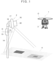
- FIG.1 shows general features of a surveying system according to a first embodiment, and the surveying system is mainly constituted of a height measuring device 1 and a high-low measuring device 2. It is to be noted that, in FIG.1 , a reference numeral 4 denotes an unevenness map (to be described later).
- a laser level planer 3 is used as the height measuring device 1.
- the laser level planer 3 forms a horizontal reference plane with a predetermined height by a laser beam.
- the horizontal reference plane may be formed by rotatably irradiating the laser beam on a horizontal plane or may be formed by horizontally irradiating a fan-shaped laser beam.
- a horizontal reference plane O is formed by rotatably irradiating the laser beam is described.
- the laser level planer 3 is installed at a necessary position via a support device such as a tripod.
- the laser level planer 3 mainly includes a control module 5, a first tilt sensor 6, a laser beam irradiation module 7, a leveling module 8, a horizontal rotation driving module 9, an operation module 11, and a display unit 12.
- the first tilt sensor 6 detects a tilt of the laser level planer 3 with respect to the horizontality, that is, a tilt of a laser beam as irradiated with respect to the horizontality. A detection result of the first tilt sensor 6 is input to the control module 5.
- the control module 5 drives the leveling module 8 based on a detection result of the first tilt sensor 6, and adjusts the laser level planer 3 to the horizontality.
- the control module 5 makes the laser beam irradiation module 7 to irradiate the laser beam, makes the horizontal rotation driving module 9 to rotate the laser beam irradiation module 7, and rotatably irradiates the laser beam such that the horizontal reference plane O is formed.
- the laser level planer 3 is installed so that the horizontal reference plane O is at a known height. For instance, a height of the horizontal reference plane O from a floor surface serving as a reference is known by actual measurements or based on specifications of the laser level planer 3 and the like. When the known horizontal reference plane O is formed, the height of an object can be measured with reference to the horizontal reference plane O.
- An instruction to turn ON/OFF operations of the laser level planer 3, settings of operation conditions, and the like are input to the control module 5 from the operation module 11, and an operation state and the like are displayed on the display unit 12.
- the high-low measuring device 2 includes a pole 14, a photodetector 15 as an object to be measured which is provided at a necessary height of the pole 14, a distance measurement sensor 16 provided at an upper end of the pole 14, a projector 17 as a projecting device, a second tilt sensor 18, and an arithmetic control module 19.
- the photodetector 15 and the distance measurement sensor 16 are provided in a known positional relationship.
- the photodetector 15 has a photodetection sensor 21 which extends in an up-and-down direction and has a predetermined length, and the photodetection sensor 21 detects the laser beam and produces a detecting signal.
- the photodetection sensor 21 has a photodetection reference position (for instance, the center of the up-and-down direction of the photodetection sensor 21 or a lower end of the photodetection sensor 21), and the photodetection reference position is a known position in the high-low measuring device 2. For instance, a distance between the photodetection reference position and the lower end of the pole 14 is known.
- the detecting signal includes a photodetecting signal and a detecting position information.
- As the detecting position information a deviation with respect to the photodetection reference position and the like are included. Therefore, based on the detecting signal, a height of the photodetection reference position with respect to the horizontal reference plane O is able to be measured.
- the detecting signal is input to the arithmetic control module 19.
- the distance measurement sensor 16 is directed downward and measures a distance to the ground surface, and various kinds of distance measurement sensors 16 can be adopted.
- a distance measurement camera 22 is used as the distance measurement sensor 16.
- the distance measurement camera 22 has an image pickup element consisting of many pixels, emits a distance measuring light for each pixel, receives a reflected light for each pixel, performs the distance measurement based on TOF (Time Of Flight) for each pixel, and planarly acquires the distance measurement data like an image.
- the distance measuring light may be scanned with a high-speed and the measurement may be planarly performed.
- the distance measurement data is input to the arithmetic control module 19.
- the distance measurement camera 22 has a measurement reference position, and a distance measured by the distance measurement camera 22 is a distance from the measurement reference position. A distance between the measurement reference position and the lower end of the pole 14 is also known. Further, a relationship between the measurement reference position of the distance measurement camera 22 and a photodetection reference position of the photodetection sensor 21 is known, and a vertical distance between the measurement reference position and the photodetection reference position is also known.
- a relationship between the measurement reference position and a reference point of a projection optical system of the projector 17 is known, and an optical axis of the distance measurement camera 22 and an optical axis of the projector 17 are parallel or substantially parallel, and a distance between both the optical axes is also known.
- the second tilt sensor 18 detects a tilt of the distance measurement camera 22 with respect to the horizontality or a tilt of the optical axis of the distance measurement camera 22 with respect to the verticality. Alternatively, a tilt of the pole 14 with respect to the verticality is detected. A tilt detection result of the second tilt sensor 18 is input to the arithmetic control module 19.
- the optical axis of the distance measurement camera 22 is set parallel to the pole 14. It is to be noted that, when the second tilt sensor 18 is configured to detect a tilt of the pole 14 with respect to the verticality, the optical axis of the distance measurement camera 22 tilts with respect to the pole 14 at a known angle.
- the second tilt sensor 18 may be incorporated in the arithmetic control module 19. Further, as the second tilt sensor 18, various kinds of IMU sensors such as an acceleration sensor or a gyroscope sensor can be used.
- the arithmetic control module 19 includes an arithmetic processing module 24 and a storage module 25.
- arithmetic processing module 24 a CPU specialized to the present embodiment, a general-purpose CPU, an embedded CPU, a microprocessor, or the like is used.
- the storage module 25 a semiconductor memory such as a RAM, a ROM, or a Flash ROM, or a DRAM, or a magnetic recording memory such as an HDD is used.
- the arithmetic processing module 24 develops various kinds of programs stored in the storage module 25, and performs necessary processing and operations.
- the programs include, for instance, a control program for integrally controlling the synchronization of the distance measurement camera 22 and the projector 17 or the like, a distance measurement program for making the distance measurement camera 22 to perform the image pickup and the distance measurement, an arithmetic program for calculating the three-dimensional data based on the distance measurement data, a program for calculating a video signal based on the three-dimensional data, and the like.
- the high-low state includes a state of a deviation with respect to a set height of an object surface to be measured, a state of irregularities (unevenness) with respect to a set plane, and a state of a tilt with respect to a horizontal plane.
- the high-low information includes an information of a deviation with respect to a set height of an object surface, an information of unevenness with respect to a set plane, and an information of a state of a tilt with respect to a horizontal plane.
- a reference numeral 27 denotes a floor surface serving as a reference
- the laser level planer 3 is installed at a known height with respect to the floor surface 27 and forms a horizontal reference plane O of a known height with respect to the floor surface 27.
- a measurer butts the pole 14 on the construction floor surface 28 and supports the high-low measuring device 2 vertically or substantially vertically.
- a vertical state of the high-low measuring device 2 is detected by the second tilt sensor 18.
- a reference sign O1 denotes a horizontal line running through a measurement reference position of the distance measurement camera 22
- a reference sign O2 denotes a horizontal line running through a photodetection reference position of the photodetection sensor 21.
- the construction finished surface 28a is set to a height difference D with respect to the horizontal reference plane O such that a predetermined placing thickness can be obtained.
- the measurement reference position and the photodetection reference position have the known relationship, and a distance between O1 and O2 has the known value d. Further, a deviation ⁇ between a laser beam receiving position of the photodetection sensor 21 and the photodetection reference position (that is, a deviation ⁇ between the horizontal reference plane O and the photodetection reference position) is provided, and a distance measurement value S (that is, a distance between the measurement reference position of the distance measurement camera 22 and a construction surface 28b) of the construction surface (a concrete placing surface) 28b as measured by the distance measurement camera 22 is provided.
- the unevenness ⁇ F of the construction surface 28b with reference to the construction finished surface 28a is acquired by the following expression.
- ⁇ F D + d ⁇ ⁇ ⁇ S
- ⁇ is + above the photodetection reference position and - below the same.
- a positive value indicates a state which is convex compared with the construction finished surface 28a and a negative value indicates a state which is concave compared to the same.
- the height difference D and the distance d between the measurement reference position and the photodetection reference position are set in the arithmetic control module 19 in advance, and a distance measurement result of the distance measurement camera 22 and a detecting signal of the photodetection sensor 21 are input to the arithmetic control module 19, respectively.
- the arithmetic control module 19 calculates the unevenness ⁇ F based on the height difference D, the distance d, the distance measurement result, and the detecting signal.
- the distance measurement camera 22 is capable of performing the distance measurement in units of pixel of the image pickup element.
- the arithmetic control module 19 calculates the unevenness ⁇ F in units of pixel and thereby acquires an unevenness ⁇ F distribution of an entire angle of field of the distance measurement camera 22.
- the arithmetic control module 19 classifies the unevenness ⁇ F with the use of a threshold value set in the storage module 25, and can create an unevenness map 4.
- the unevenness ⁇ F is + with respect to the construction finished surface 28a
- a warm color group is used, and the color density or the color tone is made darker for each 3 mm increase, for instance.
- a cool color group is used, and the color density or the color tone is made darker for each 3 mm decrease, for instance.
- the unevenness map 4 shown in FIG.1 the unevenness state is indicated by the shading.
- the threshold value for classifying can be appropriately set to 5 mm or 1 cm, for instance, without being restricted to 3 mm. Further, the classifying may be indicated in one color and the shading only.
- the arithmetic control module 19 inputs the created unevenness map to the projector 17 as a video signal, and the unevenness map 4 is projected onto the construction surface 28b by the projector 17.
- a position and a range of the unevenness map 4 to be projected coincide with a position and a distance measurement range as measured by the distance measurement camera 22, and the unevenness information of the construction surface 28b is accurately displayed by the unevenness map 4. Further, a worker can visually confirm the unevenness state of the construction surface 28b from the projected unevenness map 4.
- the projection of the unevenness map 4 may be continuous or may be blinked.
- the worker can confirm in real time the unevenness state when the concrete is placed, and the unevenness state can be corrected in real time. Therefore, the concrete placing work can be performed while correcting the unevenness state.
- the high-low measuring device 2 includes a second tilt sensor 18, which detects a tilt of the high-low measuring device 2 (the pole 14 or an optical axis of the distance measurement camera 22) in real time, and a tilt detection result is input to the arithmetic control module 19 in real time.
- the arithmetic control module 19 corrects measurement results (a measured distance, a measured position) of the distance measurement camera 22 in real time based on a distance from the lower end of the pole 14 to the measurement reference position and the tilt detection result. Therefore, even if the high-low measuring device 2 has tilted or shaken, the corrected unevenness map is projected, and the measurer can confirm the accurate high-low information.
- Step 02 to Step 10 are repeatedly performed.
- FIG.6 shows a modification of the first embodiment.
- FIG.6 what are equivalent to components as shown in FIG.1 are referred by the same symbol, and the detailed description thereof will be omitted.
- a target plate 31 for distance calibration is provided at a necessary position of a pole 14.
- a distance between the target plate 31 and a reference position of a distance measurement camera 22 is actually measured or made known from a drawing, and the known distance is determined as an actually measured value.
- a reference numeral 4 denotes a projected unevenness map.
- the target plate 31 is measured before the fact, after the fact or simultaneously, a distance measurement result of the target plate 31 as obtained by the distance measurement camera 22 is compared with the actually measured value, and the distance measurement camera 22 is calibrated. Errors possessed by the distance measurement camera 22 are corrected by the calibration, and a measurement accuracy is improved.
- FIG.7 shows general features of a surveying system according to a second embodiment, and the surveying system is mainly constituted of a height measuring device 1 and a high-low measuring device 2. It is to be noted that, in FIG.7 , a reference numeral 4 denotes a projected unevenness map.
- FIG.7 what are equivalent to components as shown in FIG.1 are referred by the same symbol, and the detailed description thereof will be omitted. It is to be noted that a laser level planer 3 is not shown in FIG.7 .
- a distance measurement sensor 16 is constituted of a projector 17 and a camera 33.
- An optical axis of the projector 17 and an optical axis of the camera 33 are parallel, and both the optical axes are separated by a predetermined distance.
- the separation distance between the respective optical axes is known, and is a distance p by which a sufficient parallax is obtained to measure the floor surface. Therefore, the projector 17 and the camera 33 is a distance measurement sensor 16 which performs the distance measurement using the parallax.
- the projector 17 projects an image including a pattern 34 for the distance measurement ( FIG.8A ).
- FIG.8A shows a grid-like pattern, but it is sufficient that the pattern is capable of confirming a displacement due to the parallax, and the pattern may be a dot pattern in which dots are distributed vertically and horizontally at predetermined intervals.
- the pattern 34 projected onto the floor surface is picked up by the camera 33.
- an intersection (a black circle) in the pattern 34 is displaced to a position of a white circle. Since this displacement amount corresponds to a size of the unevenness, when obtaining a displacement amount of each intersection in the entire pattern 34, it is possible to measure an unevenness state based on the displacement amounts.
- an unevenness map 4 can be created.
- This unevenness map 4 may be projected on the pattern 34 so as to be superimposed (see FIG.8B ), or the unevenness map 4 alone may be projected.
- the distance measurement sensor 16 may be constituted of two cameras (a parallax camera) with a predetermined parallax.
- FIG.9 and FIG.12 show general features of a surveying system according to the third embodiment, and the surveying system is mainly constituted of a height measuring device 1 and a high-low measuring device 2 similarly to the first embodiment.
- an electro-optical distance device with a tracking function for instance, a total station 37 is used as the height measuring device 1.
- a tracking function for instance, the tracking based on images using an image sensor, the shape tracking using a laser scanner, or the like.
- FIG.9 what are equivalent to components as shown in FIG.1 are referred by same symbol, and the detailed description thereof will be omitted.
- the total station 37 is horizontally leveled and installed at a necessary position.
- the total station 37 is installed at a known height. That is, the total station 37 has a survey reference point and is installed so that three-dimensional coordinates of the survey reference point, or at least height coordinates (a height position) are known. For instance, by referring to FIG.12 , assuming that the total station 37 is installed on the floor surface 27 and the floor surface 27 has a survey reference height, a height D from the floor surface 27 to the survey reference point is known.
- a high-low measuring device 2 has a prism 35 with retroreflective characteristics as an object to be measured for the height measurement.
- An optical center of the prism 35 and a measurement reference position of the distance measurement camera 22 have a known relationship. It is to be noted that a reflective sheet may be used as the object.
- the total station 37 includes a telescope module (not shown) which sights the prism 35 as the object, projects a tracking light via the telescope module, and tracks the prism 35. Further, the total station 37 projects a distance measuring light via the telescope module, receives a reflected light from the prism 35, and performs the electro-optical distance measurement with respect to the prism 35.
- a telescope module not shown which sights the prism 35 as the object, projects a tracking light via the telescope module, and tracks the prism 35. Further, the total station 37 projects a distance measuring light via the telescope module, receives a reflected light from the prism 35, and performs the electro-optical distance measurement with respect to the prism 35.
- the total station 37 mainly includes an arithmetic control module 38, a TS communication module 42, a storage module 43, a distance measuring module 44, a tracking module 45, a horizontal angle detector 47, a vertical angle detector 48, a horizontal rotation driving module 49, a vertical rotation driving module 50, a display unit 51, and an operation module 52.
- the arithmetic control module 38 performs individually controlling the TS communication module 42, the distance measuring module 44, the tracking module 45, the horizontal rotation driving module 49, the vertical rotation driving module 50 and the display unit 51 such as driving control and synchronous control and integrally controlling these modules.
- the TS communication module 42 performs the data communication with the high-low measuring device 2, and the tracking module 45 projects a tracking light, receives a reflected light from the prism 35, and carries out the tracking. Further, in parallel with the tracking by the tracking module 45, the distance measuring module 44 projects a distance measuring light and receives the reflected light from the prism 35, and performs the distance measurement with the prism 35 as an object.
- the horizontal angle detector 47 has a reference point, and is configured to detect a horizontal angle of an optical axis of a telescope with respect to this reference point. Further, the vertical angle detector 48 is configured to detect a high-low angle with respect to the horizontality.
- the horizontal rotation driving module 49 and the vertical rotation driving module 50 horizontally rotate and vertically rotate the telescope so that the prism 35 is tracked.
- the horizontal angle detector 47 and the vertical angle detector 48 detect a horizontal angle and a vertical angle in the distance measurement. Therefore, an object is subjected to the distance measurement, and three-dimensional coordinates of the object are determined.
- the TS communication module 42 transmits the determined three-dimensional coordinates to the high-low measuring device 2 in real time.
- the ON/OFF of operations, settings of operation conditions of the total station 37, and the like are input from the operation module 52, and an operation state and the like of the total station 37 are displayed in the display unit 12.
- FIG.11 shows general features of the high-low measuring device 2 of the third embodiment, the high-low measuring device 2 in the third embodiment and the high-low measuring device 2 in the first embodiment have substantially the same structure, the prism 35 is provided in place of the photodetector 15, and the high-low measuring device 2 includes a terminal communication module 53 for the data communication with the total station 37.
- a distance measurement camera 22 is shown as the distance measurement sensor 16, but the distance measurement sensor 16 may be constituted of the projector 17 and the camera 33, or a parallax camera as illustrated in the second embodiment.
- FIG.12 A description will be given on the unevenness measurement in the third embodiment by referring to FIG.12 . It is to be noted that, in FIG.12 , what are equivalent to components as shown in FIG.4 are referred by the same symbol, and the detailed description thereof will be omitted.
- the prism 35 is measured by the total station 37, and the total station 37 transmits three-dimensional coordinates of the prism 35 as the measurement data from the TS communication module 42 to the terminal communication module 53 of the high-low measuring device 2.
- the terminal communication module 53 inputs the received three-dimensional data to the arithmetic control module 19.
- the three-dimensional data is further input to the arithmetic processing module 24, and the arithmetic processing module 24 acquires a height of the prism 35 from the three-dimensional data, that is, a height of an irradiation position of the distance measuring light of the total station 37.
- the acquired height of the irradiation position of the distance measuring light is a height of the prism 35 (a height of the optical center of the prism 35) with reference to the floor surface 27 (see FIG.4 ).
- the arithmetic processing module 24 is capable of acquiring a height of the distance measurement camera 22 with reference to the floor surface 27 from a known relationship between the optical center of the prism 35 and the measurement reference position of the distance measurement camera 22 and from the height of the prism 35.
- an unevenness state of the construction surface 28b can be measured from the measurement result of the distance measurement camera 22.
- the creation of the unevenness map 4 and the projection of an unevenness map image onto the construction surface 28b are the same as the first embodiment, and hence a description thereof will be omitted.
- FIG.13A, FIG.13B and FIG.13C A description will be given on a fourth embodiment by referring to FIG.13A, FIG.13B and FIG.13C .
- a distance measurement sensor 16 is constituted of a laser length measuring device which projects a single beam (not shown) and an LED illuminator 55.
- An optical axis of the laser length measuring device is parallel or substantially parallel to that of the LED illuminator 55, and a distance between the optical axes is known.
- Illumination lights projected from the LED illuminator 55 are set as visible lights with different wavelengths (different colors). For instance, colors of the illumination lights as emitted from the LED illuminator are set to red, blue, and green.
- LED illuminators 55 of different colors may be provided with their optical axes aligned, alternatively, one LED illuminator 55 may be used, which is capable of projecting the illumination lights of a plurality of colors and of changing over colors of the illumination lights and then irradiating the illumination lights.
- the illumination light may have the necessary spread. For instance, a diameter may become 5 cm on an irradiated surface. It is to be noted that the spread of the illumination light may be appropriately changeable in correspondence with a work state, and the diameter is not limited to 5 cm.
- the LED illuminator 55 has a function as a projector, and the projector 17 is omitted in the fourth embodiment.
- the fourth embodiment illustrates a case where a laser level planer 3 is used as a height measuring device 1, but it is needless to say that the embodiment is possible even if a total station 37 is used.
- a photodetection sensor 21 of a photodetector 15 detects a horizontal reference plane O, and thereby, it is possible to acquire a height of a measurement reference position of the laser length measuring device, and an unevenness amount of a construction surface 28b (see FIG.4 ) can be measured from a measurement result of the laser length measuring device.
- An arithmetic control module 19 changes a color of illumination light from the LED illuminator 55 in correspondence with the unevenness amount and selects a color of the illumination light. By changing the color of the illumination light as irradiated on the construction surface 28b in correspondence with the unevenness amount, it is possible to visually confirm an unevenness state of a measuring position.
- a green illumination light G is irradiated ( FIG.13A ) in case of an appropriate range (for instance, ⁇ 3 mm with respect to a construction finished surface 28a (see FIG.4 ))
- a red illumination light R is irradiated ( FIG.13B ) in case of a convexity beyond the appropriate range
- a blue illumination light B is irradiated in case of a concavity beyond the appropriate range.
- the high-low measuring device 2 can be a handheld type without being installed on a construction floor surface 28.
- a height of the high-low measuring device 2 (that is, a height of a prism 35) is measured in real time by the total station 37, and a tilt of the high-low measuring device 2 (a tilt of the distance measurement sensor 16) is detected in real time by a second tilt sensor 18. Further, by correcting the measured height of the high-low measuring device 2 with the detected tilt, an accurate height of the distance measurement sensor 16 is obtained. Therefore, an accurate unevenness amount is determined from a measured value of the distance measurement sensor 16.
- the high-low measuring device 2 is a handheld type and the distance measurement sensor 16 includes the LED illuminator 55 as illustrated in the fourth embodiment
- the color of the illumination light changes in correspondence with the unevenness state. Therefore, by swinging the high-low measuring device 2 at a visible speed and within a visible range, it is possible to recognize the irradiation by the illumination light as the unevenness map.
- the high-low measuring device has casters for moving or is mounted on a moving vehicle, and thereby the high-low measuring device is capable of irradiating while being moved by remote controlling or a program.
- the case of measuring the unevenness on the object surface or the construction surface has been described above, it is needless to say that by measuring a deviation with respect to the object surface or to a set height of the construction surface (a construction finished surface), or by measuring a plurality of points on the construction surface, a tilt with respect to the horizontality can be measured.
Landscapes
- Engineering & Computer Science (AREA)
- Physics & Mathematics (AREA)
- General Physics & Mathematics (AREA)
- Radar, Positioning & Navigation (AREA)
- Remote Sensing (AREA)
- Computer Vision & Pattern Recognition (AREA)
- Theoretical Computer Science (AREA)
- Geometry (AREA)
- Multimedia (AREA)
- Signal Processing (AREA)
- Quality & Reliability (AREA)
- Length Measuring Devices By Optical Means (AREA)
Applications Claiming Priority (1)
| Application Number | Priority Date | Filing Date | Title |
|---|---|---|---|
| JP2021160383A JP2023050332A (ja) | 2021-09-30 | 2021-09-30 | 測量システム |
Publications (1)
| Publication Number | Publication Date |
|---|---|
| EP4160144A1 true EP4160144A1 (en) | 2023-04-05 |
Family
ID=83457399
Family Applications (1)
| Application Number | Title | Priority Date | Filing Date |
|---|---|---|---|
| EP22197653.3A Pending EP4160144A1 (en) | 2021-09-30 | 2022-09-26 | Surveying system |
Country Status (3)
| Country | Link |
|---|---|
| US (1) | US20230097350A1 (ja) |
| EP (1) | EP4160144A1 (ja) |
| JP (1) | JP2023050332A (ja) |
Families Citing this family (1)
| Publication number | Priority date | Publication date | Assignee | Title |
|---|---|---|---|---|
| CN112611395B (zh) * | 2020-12-31 | 2022-07-08 | 美国西北仪器公司 | 校准激光扫平仪的方法和系统 |
Citations (3)
| Publication number | Priority date | Publication date | Assignee | Title |
|---|---|---|---|---|
| JP2003082990A (ja) * | 2001-09-13 | 2003-03-19 | Nippon Koki Kk | トンネル掘削機の位置計測装置 |
| US20200271758A1 (en) * | 2019-02-26 | 2020-08-27 | Topcon Corporation | Target Instrument And Surveying System |
| US20210214922A1 (en) * | 2018-02-19 | 2021-07-15 | The University Of Tokyo | Display system for work vehicle and generation method |
-
2021
- 2021-09-30 JP JP2021160383A patent/JP2023050332A/ja active Pending
-
2022
- 2022-09-22 US US17/950,221 patent/US20230097350A1/en active Pending
- 2022-09-26 EP EP22197653.3A patent/EP4160144A1/en active Pending
Patent Citations (3)
| Publication number | Priority date | Publication date | Assignee | Title |
|---|---|---|---|---|
| JP2003082990A (ja) * | 2001-09-13 | 2003-03-19 | Nippon Koki Kk | トンネル掘削機の位置計測装置 |
| US20210214922A1 (en) * | 2018-02-19 | 2021-07-15 | The University Of Tokyo | Display system for work vehicle and generation method |
| US20200271758A1 (en) * | 2019-02-26 | 2020-08-27 | Topcon Corporation | Target Instrument And Surveying System |
Also Published As
| Publication number | Publication date |
|---|---|
| JP2023050332A (ja) | 2023-04-11 |
| US20230097350A1 (en) | 2023-03-30 |
Similar Documents
| Publication | Publication Date | Title |
|---|---|---|
| CN111238453B (zh) | 智能定位模块 | |
| CN100580374C (zh) | 激光测定方法及激光测定系统 | |
| US8345928B2 (en) | Localizing a surveying instrument in relation to a ground mark | |
| US9605957B2 (en) | Surveying instrument and method to install surveying instrument | |
| US9354054B2 (en) | Surveying system | |
| US9279679B2 (en) | Construction machine control method and construction machine control system | |
| US9719781B2 (en) | Measuring method and measuring instrument | |
| US10469754B2 (en) | Position guiding device, position guiding method, and position guiding program | |
| US20110043620A1 (en) | Determining coordinates of a target in relation to a survey instrument having at least two cameras | |
| US9776320B2 (en) | Measurement and installation data indicating apparatus and measurement and installation data indicating method | |
| EP2788715B1 (en) | Robotic leveling | |
| KR102154984B1 (ko) | 지아이에스를 기반으로 공간정보의 위치변화 영상을 처리하는 영상처리 시스템 | |
| US11421989B2 (en) | Surveying instrument | |
| KR101743392B1 (ko) | 안전성 평가를 위한 도로 기하구조 분석장치 및 그 분석방법 | |
| EP4160144A1 (en) | Surveying system | |
| JP6201252B1 (ja) | 位置計測装置及び位置計測方法 | |
| US20210302162A1 (en) | Surveying Instrument And Surveying System | |
| US6611664B2 (en) | Stereo image photographing system | |
| US20200386546A1 (en) | Surveying Instrument | |
| EP2240741B1 (en) | Localizing a surveying instrument in relation to a ground mark | |
| JPH07139942A (ja) | 測量装置 | |
| KR101172873B1 (ko) | 터널 및 사면 조사용 입체 영상 촬영 장치 | |
| US20200081266A1 (en) | Surveying Instrument | |
| JPH08210854A (ja) | コード化された水準測量捍の傾斜角を決定する方法 | |
| US20210382143A1 (en) | Surveying Instrument And Surveying System |
Legal Events
| Date | Code | Title | Description |
|---|---|---|---|
| PUAI | Public reference made under article 153(3) epc to a published international application that has entered the european phase |
Free format text: ORIGINAL CODE: 0009012 |
|
| STAA | Information on the status of an ep patent application or granted ep patent |
Free format text: STATUS: REQUEST FOR EXAMINATION WAS MADE |
|
| 17P | Request for examination filed |
Effective date: 20220926 |
|
| AK | Designated contracting states |
Kind code of ref document: A1 Designated state(s): AL AT BE BG CH CY CZ DE DK EE ES FI FR GB GR HR HU IE IS IT LI LT LU LV MC MK MT NL NO PL PT RO RS SE SI SK SM TR |
|
| RBV | Designated contracting states (corrected) |
Designated state(s): AL AT BE BG CH CY CZ DE DK EE ES FI FR GB GR HR HU IE IS IT LI LT LU LV MC MK MT NL NO PL PT RO RS SE SI SK SM TR |
|
| GRAP | Despatch of communication of intention to grant a patent |
Free format text: ORIGINAL CODE: EPIDOSNIGR1 |
|
| STAA | Information on the status of an ep patent application or granted ep patent |
Free format text: STATUS: GRANT OF PATENT IS INTENDED |
|
| INTG | Intention to grant announced |
Effective date: 20240404 |