EP4160132A1 - Rohrwicklung einer gaskondensationswärmeaustauschzelle für einen kessel - Google Patents
Rohrwicklung einer gaskondensationswärmeaustauschzelle für einen kessel Download PDFInfo
- Publication number
- EP4160132A1 EP4160132A1 EP22178478.8A EP22178478A EP4160132A1 EP 4160132 A1 EP4160132 A1 EP 4160132A1 EP 22178478 A EP22178478 A EP 22178478A EP 4160132 A1 EP4160132 A1 EP 4160132A1
- Authority
- EP
- European Patent Office
- Prior art keywords
- sides
- tube
- value
- tube profile
- curvature
- Prior art date
- Legal status (The legal status is an assumption and is not a legal conclusion. Google has not performed a legal analysis and makes no representation as to the accuracy of the status listed.)
- Granted
Links
- 238000004804 winding Methods 0.000 title claims description 56
- 238000009833 condensation Methods 0.000 title description 3
- 230000005494 condensation Effects 0.000 title description 3
- 238000004519 manufacturing process Methods 0.000 claims abstract description 10
- 239000003517 fume Substances 0.000 claims description 64
- 238000002485 combustion reaction Methods 0.000 claims description 34
- 239000012530 fluid Substances 0.000 claims description 15
- 238000010438 heat treatment Methods 0.000 claims description 14
- 239000007789 gas Substances 0.000 claims description 10
- 239000013529 heat transfer fluid Substances 0.000 claims description 10
- 230000003247 decreasing effect Effects 0.000 claims description 3
- XLYOFNOQVPJJNP-UHFFFAOYSA-N water Substances O XLYOFNOQVPJJNP-UHFFFAOYSA-N 0.000 description 12
- 239000003344 environmental pollutant Substances 0.000 description 11
- 231100000719 pollutant Toxicity 0.000 description 11
- 239000000463 material Substances 0.000 description 6
- 239000000203 mixture Substances 0.000 description 3
- 238000010276 construction Methods 0.000 description 2
- 230000003628 erosive effect Effects 0.000 description 2
- 229910052751 metal Inorganic materials 0.000 description 2
- 239000002184 metal Substances 0.000 description 2
- 238000000034 method Methods 0.000 description 2
- 229910000831 Steel Inorganic materials 0.000 description 1
- 230000006978 adaptation Effects 0.000 description 1
- 239000000956 alloy Substances 0.000 description 1
- 229910045601 alloy Inorganic materials 0.000 description 1
- 229910052782 aluminium Inorganic materials 0.000 description 1
- XAGFODPZIPBFFR-UHFFFAOYSA-N aluminium Chemical compound [Al] XAGFODPZIPBFFR-UHFFFAOYSA-N 0.000 description 1
- 230000009286 beneficial effect Effects 0.000 description 1
- 230000015572 biosynthetic process Effects 0.000 description 1
- 229910002091 carbon monoxide Inorganic materials 0.000 description 1
- 230000000052 comparative effect Effects 0.000 description 1
- 230000001419 dependent effect Effects 0.000 description 1
- 230000007613 environmental effect Effects 0.000 description 1
- 239000007788 liquid Substances 0.000 description 1
- 238000012423 maintenance Methods 0.000 description 1
- 230000003334 potential effect Effects 0.000 description 1
- 230000005855 radiation Effects 0.000 description 1
- 239000010959 steel Substances 0.000 description 1
Images


Classifications
-
- F—MECHANICAL ENGINEERING; LIGHTING; HEATING; WEAPONS; BLASTING
- F24—HEATING; RANGES; VENTILATING
- F24H—FLUID HEATERS, e.g. WATER OR AIR HEATERS, HAVING HEAT-GENERATING MEANS, e.g. HEAT PUMPS, IN GENERAL
- F24H1/00—Water heaters, e.g. boilers, continuous-flow heaters or water-storage heaters
- F24H1/22—Water heaters other than continuous-flow or water-storage heaters, e.g. water heaters for central heating
- F24H1/40—Water heaters other than continuous-flow or water-storage heaters, e.g. water heaters for central heating with water tube or tubes
- F24H1/43—Water heaters other than continuous-flow or water-storage heaters, e.g. water heaters for central heating with water tube or tubes helically or spirally coiled
-
- F—MECHANICAL ENGINEERING; LIGHTING; HEATING; WEAPONS; BLASTING
- F24—HEATING; RANGES; VENTILATING
- F24H—FLUID HEATERS, e.g. WATER OR AIR HEATERS, HAVING HEAT-GENERATING MEANS, e.g. HEAT PUMPS, IN GENERAL
- F24H1/00—Water heaters, e.g. boilers, continuous-flow heaters or water-storage heaters
- F24H1/10—Continuous-flow heaters, i.e. heaters in which heat is generated only while the water is flowing, e.g. with direct contact of the water with the heating medium
- F24H1/12—Continuous-flow heaters, i.e. heaters in which heat is generated only while the water is flowing, e.g. with direct contact of the water with the heating medium in which the water is kept separate from the heating medium
- F24H1/14—Continuous-flow heaters, i.e. heaters in which heat is generated only while the water is flowing, e.g. with direct contact of the water with the heating medium in which the water is kept separate from the heating medium by tubes, e.g. bent in serpentine form
- F24H1/16—Continuous-flow heaters, i.e. heaters in which heat is generated only while the water is flowing, e.g. with direct contact of the water with the heating medium in which the water is kept separate from the heating medium by tubes, e.g. bent in serpentine form helically or spirally coiled
- F24H1/165—Continuous-flow heaters, i.e. heaters in which heat is generated only while the water is flowing, e.g. with direct contact of the water with the heating medium in which the water is kept separate from the heating medium by tubes, e.g. bent in serpentine form helically or spirally coiled using fluid fuel
-
- F—MECHANICAL ENGINEERING; LIGHTING; HEATING; WEAPONS; BLASTING
- F24—HEATING; RANGES; VENTILATING
- F24H—FLUID HEATERS, e.g. WATER OR AIR HEATERS, HAVING HEAT-GENERATING MEANS, e.g. HEAT PUMPS, IN GENERAL
- F24H8/00—Fluid heaters characterised by means for extracting latent heat from flue gases by means of condensation
-
- F—MECHANICAL ENGINEERING; LIGHTING; HEATING; WEAPONS; BLASTING
- F28—HEAT EXCHANGE IN GENERAL
- F28D—HEAT-EXCHANGE APPARATUS, NOT PROVIDED FOR IN ANOTHER SUBCLASS, IN WHICH THE HEAT-EXCHANGE MEDIA DO NOT COME INTO DIRECT CONTACT
- F28D21/00—Heat-exchange apparatus not covered by any of the groups F28D1/00 - F28D20/00
- F28D21/0001—Recuperative heat exchangers
- F28D21/0003—Recuperative heat exchangers the heat being recuperated from exhaust gases
- F28D21/0005—Recuperative heat exchangers the heat being recuperated from exhaust gases for domestic or space-heating systems
- F28D21/0007—Water heaters
-
- F—MECHANICAL ENGINEERING; LIGHTING; HEATING; WEAPONS; BLASTING
- F28—HEAT EXCHANGE IN GENERAL
- F28D—HEAT-EXCHANGE APPARATUS, NOT PROVIDED FOR IN ANOTHER SUBCLASS, IN WHICH THE HEAT-EXCHANGE MEDIA DO NOT COME INTO DIRECT CONTACT
- F28D7/00—Heat-exchange apparatus having stationary tubular conduit assemblies for both heat-exchange media, the media being in contact with different sides of a conduit wall
- F28D7/02—Heat-exchange apparatus having stationary tubular conduit assemblies for both heat-exchange media, the media being in contact with different sides of a conduit wall the conduits being helically coiled
- F28D7/024—Heat-exchange apparatus having stationary tubular conduit assemblies for both heat-exchange media, the media being in contact with different sides of a conduit wall the conduits being helically coiled the conduits of only one medium being helically coiled tubes, the coils having a cylindrical configuration
-
- F—MECHANICAL ENGINEERING; LIGHTING; HEATING; WEAPONS; BLASTING
- F28—HEAT EXCHANGE IN GENERAL
- F28F—DETAILS OF HEAT-EXCHANGE AND HEAT-TRANSFER APPARATUS, OF GENERAL APPLICATION
- F28F1/00—Tubular elements; Assemblies of tubular elements
- F28F1/02—Tubular elements of cross-section which is non-circular
- F28F1/04—Tubular elements of cross-section which is non-circular polygonal, e.g. rectangular
-
- F—MECHANICAL ENGINEERING; LIGHTING; HEATING; WEAPONS; BLASTING
- F28—HEAT EXCHANGE IN GENERAL
- F28D—HEAT-EXCHANGE APPARATUS, NOT PROVIDED FOR IN ANOTHER SUBCLASS, IN WHICH THE HEAT-EXCHANGE MEDIA DO NOT COME INTO DIRECT CONTACT
- F28D21/00—Heat-exchange apparatus not covered by any of the groups F28D1/00 - F28D20/00
- F28D2021/0019—Other heat exchangers for particular applications; Heat exchange systems not otherwise provided for
- F28D2021/0024—Other heat exchangers for particular applications; Heat exchange systems not otherwise provided for for combustion apparatus, e.g. for boilers
-
- F—MECHANICAL ENGINEERING; LIGHTING; HEATING; WEAPONS; BLASTING
- F28—HEAT EXCHANGE IN GENERAL
- F28F—DETAILS OF HEAT-EXCHANGE AND HEAT-TRANSFER APPARATUS, OF GENERAL APPLICATION
- F28F2250/00—Arrangements for modifying the flow of the heat exchange media, e.g. flow guiding means; Particular flow patterns
- F28F2250/02—Streamline-shaped elements
-
- Y—GENERAL TAGGING OF NEW TECHNOLOGICAL DEVELOPMENTS; GENERAL TAGGING OF CROSS-SECTIONAL TECHNOLOGIES SPANNING OVER SEVERAL SECTIONS OF THE IPC; TECHNICAL SUBJECTS COVERED BY FORMER USPC CROSS-REFERENCE ART COLLECTIONS [XRACs] AND DIGESTS
- Y02—TECHNOLOGIES OR APPLICATIONS FOR MITIGATION OR ADAPTATION AGAINST CLIMATE CHANGE
- Y02B—CLIMATE CHANGE MITIGATION TECHNOLOGIES RELATED TO BUILDINGS, e.g. HOUSING, HOUSE APPLIANCES OR RELATED END-USER APPLICATIONS
- Y02B30/00—Energy efficient heating, ventilation or air conditioning [HVAC]
Definitions
- the present invention belongs to the technical field of heat exchangers and relates to a tube profile for manufacturing a heat exchanger, where the tube profile is adapted to cause a first fluid to flow therein and to be externally lapped by a second fluid, allowing a heat exchange between the first fluid and the second fluid through the tube profile.
- the first fluid is a liquid, generally water, for a heating or domestic water system
- the second fluid consists of the hot combustion fumes of a gas-air mixture.
- the invention further relates to a tube winding comprising the aforesaid tube profile, suitably shaped for a gas heat exchange cell for a boiler for environmental heating and/or for heating domestic water, e.g., for a heat exchange cell for a condensing boiler.
- a condensing gas boiler for heating generally is a device in which a heat transfer fluid to be heated, generally water, flows by traveling through a heat exchanger, which is in contact with a flow of hot fumes transmitting heat to the heat transfer fluid.
- a heat exchanger for a boiler also referred to as a heat exchange cell, comprises a tube bundle in which the heat transfer fluid circulates, in particular water to be heated
- the wound tube of the tube winding has a cross section being circular in shape or rectangular with radial edges or oval or rectangular having a portion exposed to the source of heat in the shape of a semi-circle.
- the prior art also provides that there is a calibrated passage between one turn and the adjacent one, or between one tube and the adjacent one.
- the high heat exchange coefficient generated for the movement of the fumes in the passage between the turns allows reaching high levels of efficiency, but the level of pollutants generated and emitted is barely sufficient to respect current legal requirements and is elevated and beyond the limits with respect to the expectations of the future standards.
- the overall size of said ogival portion HO equal to the difference between the overall cross-section width H and the width H1 of the rectangular portion measured along the axis of symmetry S-S, is greater than the length of said base 41, thus greater than the length of the first smaller side 31 of the rectangular portion 20.
- the two greater sides 21, 22, a second side of said two smaller sides 32, and said two curved sides 42, 43 define the outer surfaces 50 of the walls of said tube profile 1.
- the cross-section 10 of the tube profile 1 preferably has a non-symmetrical shape to an axis orthogonal to the axis of symmetry S-S.
- the value of the width H1 of the rectangular portion measured along the axis of symmetry S-S is substantially equal to the value of the radius of curvature R3 of each of said two curved sides 42, 43 in said joining point PH1.
- the center of the ellipse is arranged in the central point 34 of the first smaller side 31 of the rectangular portion.
- each of the two greater sides 21, 22 of the rectangular portion 20 is connected to the second side 32 of said two smaller sides of said rectangular portion 20 by means of a respective end arc of circumference 47 having a preset end radius of curvature value R4.
- said end radius of curvature value R4 has the following value: where:
- the value of the aforesaid constant ⁇ is given by the relationship: 2.5 ⁇ ⁇ ⁇ 4
- a tube heat exchanger 100 comprising at least one tube profile 1 with any of the features described above, where the tube profile 1 is adapted to be internally crossed by a first fluid 101 to be heated, and is adapted to be externally lapped by a second heating fluid 102 according to a predetermined flow direction and orientation 103, where said predetermined flow direction 103 is orthogonal to an extension direction F-F of the tube profile, where said rectangular portion 20 of the cross-section 10 of said tube profile 1 is arranged with the two greater sides 21, 22 thereof along said predetermined flow direction 103, and with said ogival portion 40 facing an opposite direction to said predetermined flow direction 103.
- a tube winding 200 in particular for a gas condensing heat exchange cell 300 for a boiler for heating an environment.
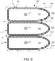
- the aforesaid tube winding 200 is formed by a tube profile 1 having any of the features described above, wound according to a plurality of turns 201 about a central winding axis C-C.
- the turns 201 of said plurality are spaced apart from one another according to a direction parallel to the central axis C-C forming calibrated axial passages (A) therebetween, adapted to be crossed, in a radial direction R with respect to said central axis C-C, from the central axis towards C-C the exterior of the tube winding.
- the combustion chamber 202 is laterally delimited by the surfaces of said turns 201, corresponding to the ogival portion 40 of each of them.
- the heat exchange cell 300 comprises a closing flange 310, preferably made from a printed sheet, configured to close a front opening 304 of the container body 203.
- the closing flange 310 has a central flange opening 311 configured to allow access to the interior of the combustion chamber 202 for carrying out maintenance.
- the closing door 320 supports, on an inner face 321 thereof, a gas burner 323 so that it is arranged, in use, inside the combustion chamber 202 and, on the outer face 322 thereof, a feeding sleeve 324 for feeding a combustible gas-air mixture to said burner 323.
- Figure 9 illustrates a comparison of the speed and temperature trends of the bullet-shaped cross-section according to the invention with respect to a traditional cross-section having the portion exposed to the fumes in the shape of a semi-circle, where the outer perimeter of the bullet-shaped cross-section is equal to the outer perimeter of the cross-section of the profile having the portion exposed to the fumes in the shape of a semi-circle.
- the continuous line 155 represents the trend of the fume temperature along the outer surface of the bullet-shaped cross-section according to the invention
- the dashed line 156 represents the trend of the fume temperature along the outer surface of the traditional cross-section having the portion exposed to the fumes shaped as a semi-circle.
Landscapes
- Engineering & Computer Science (AREA)
- Physics & Mathematics (AREA)
- Thermal Sciences (AREA)
- Mechanical Engineering (AREA)
- General Engineering & Computer Science (AREA)
- Chemical & Material Sciences (AREA)
- Combustion & Propulsion (AREA)
- Geometry (AREA)
- Heat-Exchange Devices With Radiators And Conduit Assemblies (AREA)
- Fuel Cell (AREA)
Applications Claiming Priority (1)
| Application Number | Priority Date | Filing Date | Title |
|---|---|---|---|
| IT102021000025346A IT202100025346A1 (it) | 2021-10-04 | 2021-10-04 | Avvolgimento tubiero per una cella di scambio di calore a gas per una caldaia |
Publications (2)
| Publication Number | Publication Date |
|---|---|
| EP4160132A1 true EP4160132A1 (de) | 2023-04-05 |
| EP4160132B1 EP4160132B1 (de) | 2023-10-18 |
Family
ID=79019018
Family Applications (1)
| Application Number | Title | Priority Date | Filing Date |
|---|---|---|---|
| EP22178478.8A Active EP4160132B1 (de) | 2021-10-04 | 2022-06-10 | Rohrwicklung einer gaskondensationswärmeaustauschzelle für einen kessel |
Country Status (4)
| Country | Link |
|---|---|
| US (1) | US20230108472A1 (de) |
| EP (1) | EP4160132B1 (de) |
| KR (1) | KR20230048599A (de) |
| IT (1) | IT202100025346A1 (de) |
Citations (5)
| Publication number | Priority date | Publication date | Assignee | Title |
|---|---|---|---|---|
| US20100044011A1 (en) * | 2006-02-03 | 2010-02-25 | Viessmann Werke Gmbh & Co., Kg | Heating device |
| US7909005B2 (en) * | 2007-02-28 | 2011-03-22 | Giannoni France | Condensation heat exchanger including 2 primary bundles and a secondary bundle |
| US20120055421A1 (en) * | 2009-06-10 | 2012-03-08 | Rainer Rausch | Sectional Boiler |
| US20170102164A1 (en) * | 2014-03-17 | 2017-04-13 | Condevo S.P.A. | Heat exchange cell and method |
| EP3633286A1 (de) * | 2018-10-05 | 2020-04-08 | Valmex S.p.A. | Verbesserter wärmetauscher für gasboiler |
-
2021
- 2021-10-04 IT IT102021000025346A patent/IT202100025346A1/it unknown
-
2022
- 2022-06-10 EP EP22178478.8A patent/EP4160132B1/de active Active
- 2022-09-21 KR KR1020220119483A patent/KR20230048599A/ko unknown
- 2022-09-26 US US17/952,484 patent/US20230108472A1/en active Pending
Patent Citations (5)
| Publication number | Priority date | Publication date | Assignee | Title |
|---|---|---|---|---|
| US20100044011A1 (en) * | 2006-02-03 | 2010-02-25 | Viessmann Werke Gmbh & Co., Kg | Heating device |
| US7909005B2 (en) * | 2007-02-28 | 2011-03-22 | Giannoni France | Condensation heat exchanger including 2 primary bundles and a secondary bundle |
| US20120055421A1 (en) * | 2009-06-10 | 2012-03-08 | Rainer Rausch | Sectional Boiler |
| US20170102164A1 (en) * | 2014-03-17 | 2017-04-13 | Condevo S.P.A. | Heat exchange cell and method |
| EP3633286A1 (de) * | 2018-10-05 | 2020-04-08 | Valmex S.p.A. | Verbesserter wärmetauscher für gasboiler |
Also Published As
| Publication number | Publication date |
|---|---|
| EP4160132B1 (de) | 2023-10-18 |
| US20230108472A1 (en) | 2023-04-06 |
| KR20230048599A (ko) | 2023-04-11 |
| IT202100025346A1 (it) | 2023-04-04 |
Similar Documents
| Publication | Publication Date | Title |
|---|---|---|
| US9074792B2 (en) | Multiple-ring heat exchanger | |
| US8622030B2 (en) | Spiral heat exchanger for producing heating and/or sanitary use hot water, specifically designed for condensation applications | |
| AU2016204398B2 (en) | Heat exchanger tube and heating boiler having such a heat exchanger tube | |
| US4730600A (en) | Condensing furnace | |
| US7044123B2 (en) | Highly efficient heat exchanger and combustion chamber assembly for boilers and heated air generators | |
| EP1750069B1 (de) | Wärmetauscher und dessen Herstellungsmethode | |
| US4867673A (en) | Condensing furnace | |
| EP4160132B1 (de) | Rohrwicklung einer gaskondensationswärmeaustauschzelle für einen kessel | |
| JP2986982B2 (ja) | 小型ガス燃焼空気ヒーター | |
| KR20190006245A (ko) | 나선형 복열기를 구비한 버너 | |
| CN210321317U (zh) | 一种换热器总成及壁挂炉 | |
| CN216409817U (zh) | 换热管、换热装置及热水装置 | |
| CN214370968U (zh) | 一种壁挂炉换热器 | |
| KR20000071947A (ko) | 과열기용 단일통로식 와류형성 전열장치 | |
| CN214501744U (zh) | 壁挂炉用换热器 | |
| CN209355249U (zh) | 一种炉用二次预热式空气自预热烧嘴 | |
| IE980157A1 (en) | Boiler intended to be mounted on a combustion fumes flue¹pipe | |
| SU1755011A1 (ru) | Рекуператор | |
| WO2021011627A1 (en) | Heat exchanger baffles and methods for manufacturing the same | |
| HU208732B (en) | Gas-boiler ensuring the turbulent flow of flue gases particularly for small flats | |
| WO2019169397A1 (en) | Multisection tubeless heat exchanger, fluid heating system including the same, and methods of manufacture thereof | |
| NZ721569B (en) | Heat exchanger tube and heating boiler having such a heat exchanger tube | |
| KR20040017452A (ko) | 저장식 보일러용 열교환기 | |
| EP2148148A1 (de) | Kessel mit einem Wärmeaustauscher | |
| JPS61105064A (ja) | 吸収式冷温水機の発生器 |
Legal Events
| Date | Code | Title | Description |
|---|---|---|---|
| PUAI | Public reference made under article 153(3) epc to a published international application that has entered the european phase |
Free format text: ORIGINAL CODE: 0009012 |
|
| STAA | Information on the status of an ep patent application or granted ep patent |
Free format text: STATUS: REQUEST FOR EXAMINATION WAS MADE |
|
| 17P | Request for examination filed |
Effective date: 20221107 |
|
| AK | Designated contracting states |
Kind code of ref document: A1 Designated state(s): AL AT BE BG CH CY CZ DE DK EE ES FI FR GB GR HR HU IE IS IT LI LT LU LV MC MK MT NL NO PL PT RO RS SE SI SK SM TR |
|
| GRAP | Despatch of communication of intention to grant a patent |
Free format text: ORIGINAL CODE: EPIDOSNIGR1 |
|
| STAA | Information on the status of an ep patent application or granted ep patent |
Free format text: STATUS: GRANT OF PATENT IS INTENDED |
|
| INTG | Intention to grant announced |
Effective date: 20230511 |
|
| P01 | Opt-out of the competence of the unified patent court (upc) registered |
Effective date: 20230630 |
|
| GRAS | Grant fee paid |
Free format text: ORIGINAL CODE: EPIDOSNIGR3 |
|
| GRAA | (expected) grant |
Free format text: ORIGINAL CODE: 0009210 |
|
| STAA | Information on the status of an ep patent application or granted ep patent |
Free format text: STATUS: THE PATENT HAS BEEN GRANTED |
|
| AK | Designated contracting states |
Kind code of ref document: B1 Designated state(s): AL AT BE BG CH CY CZ DE DK EE ES FI FR GB GR HR HU IE IS IT LI LT LU LV MC MK MT NL NO PL PT RO RS SE SI SK SM TR |
|
| REG | Reference to a national code |
Ref country code: GB Ref legal event code: FG4D |
|
| REG | Reference to a national code |
Ref country code: CH Ref legal event code: EP |
|
| REG | Reference to a national code |
Ref country code: IE Ref legal event code: FG4D |
|
| REG | Reference to a national code |
Ref country code: DE Ref legal event code: R096 Ref document number: 602022000719 Country of ref document: DE |
|
| REG | Reference to a national code |
Ref country code: NL Ref legal event code: FP |
|
| REG | Reference to a national code |
Ref country code: LT Ref legal event code: MG9D |
|
| REG | Reference to a national code |
Ref country code: AT Ref legal event code: MK05 Ref document number: 1622813 Country of ref document: AT Kind code of ref document: T Effective date: 20231018 |
|
| PG25 | Lapsed in a contracting state [announced via postgrant information from national office to epo] |
Ref country code: GR Free format text: LAPSE BECAUSE OF FAILURE TO SUBMIT A TRANSLATION OF THE DESCRIPTION OR TO PAY THE FEE WITHIN THE PRESCRIBED TIME-LIMIT Effective date: 20240119 |
|
| PG25 | Lapsed in a contracting state [announced via postgrant information from national office to epo] |
Ref country code: IS Free format text: LAPSE BECAUSE OF FAILURE TO SUBMIT A TRANSLATION OF THE DESCRIPTION OR TO PAY THE FEE WITHIN THE PRESCRIBED TIME-LIMIT Effective date: 20240218 |
|
| PG25 | Lapsed in a contracting state [announced via postgrant information from national office to epo] |
Ref country code: LT Free format text: LAPSE BECAUSE OF FAILURE TO SUBMIT A TRANSLATION OF THE DESCRIPTION OR TO PAY THE FEE WITHIN THE PRESCRIBED TIME-LIMIT Effective date: 20231018 |
|
| PG25 | Lapsed in a contracting state [announced via postgrant information from national office to epo] |
Ref country code: AT Free format text: LAPSE BECAUSE OF FAILURE TO SUBMIT A TRANSLATION OF THE DESCRIPTION OR TO PAY THE FEE WITHIN THE PRESCRIBED TIME-LIMIT Effective date: 20231018 |
|
| PG25 | Lapsed in a contracting state [announced via postgrant information from national office to epo] |
Ref country code: ES Free format text: LAPSE BECAUSE OF FAILURE TO SUBMIT A TRANSLATION OF THE DESCRIPTION OR TO PAY THE FEE WITHIN THE PRESCRIBED TIME-LIMIT Effective date: 20231018 |
|
| PG25 | Lapsed in a contracting state [announced via postgrant information from national office to epo] |
Ref country code: LT Free format text: LAPSE BECAUSE OF FAILURE TO SUBMIT A TRANSLATION OF THE DESCRIPTION OR TO PAY THE FEE WITHIN THE PRESCRIBED TIME-LIMIT Effective date: 20231018 Ref country code: IS Free format text: LAPSE BECAUSE OF FAILURE TO SUBMIT A TRANSLATION OF THE DESCRIPTION OR TO PAY THE FEE WITHIN THE PRESCRIBED TIME-LIMIT Effective date: 20240218 Ref country code: GR Free format text: LAPSE BECAUSE OF FAILURE TO SUBMIT A TRANSLATION OF THE DESCRIPTION OR TO PAY THE FEE WITHIN THE PRESCRIBED TIME-LIMIT Effective date: 20240119 Ref country code: ES Free format text: LAPSE BECAUSE OF FAILURE TO SUBMIT A TRANSLATION OF THE DESCRIPTION OR TO PAY THE FEE WITHIN THE PRESCRIBED TIME-LIMIT Effective date: 20231018 Ref country code: BG Free format text: LAPSE BECAUSE OF FAILURE TO SUBMIT A TRANSLATION OF THE DESCRIPTION OR TO PAY THE FEE WITHIN THE PRESCRIBED TIME-LIMIT Effective date: 20240118 Ref country code: AT Free format text: LAPSE BECAUSE OF FAILURE TO SUBMIT A TRANSLATION OF THE DESCRIPTION OR TO PAY THE FEE WITHIN THE PRESCRIBED TIME-LIMIT Effective date: 20231018 Ref country code: PT Free format text: LAPSE BECAUSE OF FAILURE TO SUBMIT A TRANSLATION OF THE DESCRIPTION OR TO PAY THE FEE WITHIN THE PRESCRIBED TIME-LIMIT Effective date: 20240219 |
|
| PG25 | Lapsed in a contracting state [announced via postgrant information from national office to epo] |
Ref country code: SE Free format text: LAPSE BECAUSE OF FAILURE TO SUBMIT A TRANSLATION OF THE DESCRIPTION OR TO PAY THE FEE WITHIN THE PRESCRIBED TIME-LIMIT Effective date: 20231018 Ref country code: RS Free format text: LAPSE BECAUSE OF FAILURE TO SUBMIT A TRANSLATION OF THE DESCRIPTION OR TO PAY THE FEE WITHIN THE PRESCRIBED TIME-LIMIT Effective date: 20231018 Ref country code: PL Free format text: LAPSE BECAUSE OF FAILURE TO SUBMIT A TRANSLATION OF THE DESCRIPTION OR TO PAY THE FEE WITHIN THE PRESCRIBED TIME-LIMIT Effective date: 20231018 Ref country code: NO Free format text: LAPSE BECAUSE OF FAILURE TO SUBMIT A TRANSLATION OF THE DESCRIPTION OR TO PAY THE FEE WITHIN THE PRESCRIBED TIME-LIMIT Effective date: 20240118 Ref country code: LV Free format text: LAPSE BECAUSE OF FAILURE TO SUBMIT A TRANSLATION OF THE DESCRIPTION OR TO PAY THE FEE WITHIN THE PRESCRIBED TIME-LIMIT Effective date: 20231018 Ref country code: HR Free format text: LAPSE BECAUSE OF FAILURE TO SUBMIT A TRANSLATION OF THE DESCRIPTION OR TO PAY THE FEE WITHIN THE PRESCRIBED TIME-LIMIT Effective date: 20231018 |
|
| PGFP | Annual fee paid to national office [announced via postgrant information from national office to epo] |
Ref country code: DE Payment date: 20240619 Year of fee payment: 3 |
|
| PG25 | Lapsed in a contracting state [announced via postgrant information from national office to epo] |
Ref country code: DK Free format text: LAPSE BECAUSE OF FAILURE TO SUBMIT A TRANSLATION OF THE DESCRIPTION OR TO PAY THE FEE WITHIN THE PRESCRIBED TIME-LIMIT Effective date: 20231018 |
|
| REG | Reference to a national code |
Ref country code: DE Ref legal event code: R097 Ref document number: 602022000719 Country of ref document: DE |
|
| PG25 | Lapsed in a contracting state [announced via postgrant information from national office to epo] |
Ref country code: CZ Free format text: LAPSE BECAUSE OF FAILURE TO SUBMIT A TRANSLATION OF THE DESCRIPTION OR TO PAY THE FEE WITHIN THE PRESCRIBED TIME-LIMIT Effective date: 20231018 |
|
| PG25 | Lapsed in a contracting state [announced via postgrant information from national office to epo] |
Ref country code: SK Free format text: LAPSE BECAUSE OF FAILURE TO SUBMIT A TRANSLATION OF THE DESCRIPTION OR TO PAY THE FEE WITHIN THE PRESCRIBED TIME-LIMIT Effective date: 20231018 |
|
| PG25 | Lapsed in a contracting state [announced via postgrant information from national office to epo] |
Ref country code: SM Free format text: LAPSE BECAUSE OF FAILURE TO SUBMIT A TRANSLATION OF THE DESCRIPTION OR TO PAY THE FEE WITHIN THE PRESCRIBED TIME-LIMIT Effective date: 20231018 Ref country code: SK Free format text: LAPSE BECAUSE OF FAILURE TO SUBMIT A TRANSLATION OF THE DESCRIPTION OR TO PAY THE FEE WITHIN THE PRESCRIBED TIME-LIMIT Effective date: 20231018 Ref country code: RO Free format text: LAPSE BECAUSE OF FAILURE TO SUBMIT A TRANSLATION OF THE DESCRIPTION OR TO PAY THE FEE WITHIN THE PRESCRIBED TIME-LIMIT Effective date: 20231018 Ref country code: EE Free format text: LAPSE BECAUSE OF FAILURE TO SUBMIT A TRANSLATION OF THE DESCRIPTION OR TO PAY THE FEE WITHIN THE PRESCRIBED TIME-LIMIT Effective date: 20231018 Ref country code: DK Free format text: LAPSE BECAUSE OF FAILURE TO SUBMIT A TRANSLATION OF THE DESCRIPTION OR TO PAY THE FEE WITHIN THE PRESCRIBED TIME-LIMIT Effective date: 20231018 Ref country code: CZ Free format text: LAPSE BECAUSE OF FAILURE TO SUBMIT A TRANSLATION OF THE DESCRIPTION OR TO PAY THE FEE WITHIN THE PRESCRIBED TIME-LIMIT Effective date: 20231018 |
|
| PGFP | Annual fee paid to national office [announced via postgrant information from national office to epo] |
Ref country code: FR Payment date: 20240528 Year of fee payment: 3 |
|
| PLBE | No opposition filed within time limit |
Free format text: ORIGINAL CODE: 0009261 |
|
| STAA | Information on the status of an ep patent application or granted ep patent |
Free format text: STATUS: NO OPPOSITION FILED WITHIN TIME LIMIT |
|
| PGFP | Annual fee paid to national office [announced via postgrant information from national office to epo] |
Ref country code: TR Payment date: 20240603 Year of fee payment: 3 |
|
| 26N | No opposition filed |
Effective date: 20240719 |