EP4159991A1 - Système de mesure de fluides à double soupape - Google Patents
Système de mesure de fluides à double soupape Download PDFInfo
- Publication number
- EP4159991A1 EP4159991A1 EP22179271.6A EP22179271A EP4159991A1 EP 4159991 A1 EP4159991 A1 EP 4159991A1 EP 22179271 A EP22179271 A EP 22179271A EP 4159991 A1 EP4159991 A1 EP 4159991A1
- Authority
- EP
- European Patent Office
- Prior art keywords
- flow
- fluid
- pump
- flow control
- fluid delivery
- Prior art date
- Legal status (The legal status is an assumption and is not a legal conclusion. Google has not performed a legal analysis and makes no representation as to the accuracy of the status listed.)
- Pending
Links
- 239000012530 fluid Substances 0.000 title claims abstract description 105
- 230000009977 dual effect Effects 0.000 title description 6
- 230000001105 regulatory effect Effects 0.000 claims abstract description 37
- 230000003134 recirculating effect Effects 0.000 claims abstract description 3
- 238000000034 method Methods 0.000 claims description 9
- 238000001816 cooling Methods 0.000 claims description 2
- 238000011144 upstream manufacturing Methods 0.000 description 5
- 238000010586 diagram Methods 0.000 description 3
- 238000005259 measurement Methods 0.000 description 2
- 238000013459 approach Methods 0.000 description 1
- 230000001276 controlling effect Effects 0.000 description 1
- 238000013016 damping Methods 0.000 description 1
- 238000006073 displacement reaction Methods 0.000 description 1
- 239000000446 fuel Substances 0.000 description 1
- 238000010438 heat treatment Methods 0.000 description 1
- 230000003993 interaction Effects 0.000 description 1
- 238000007726 management method Methods 0.000 description 1
- 239000000463 material Substances 0.000 description 1
- 238000002156 mixing Methods 0.000 description 1
- 238000012986 modification Methods 0.000 description 1
- 230000004048 modification Effects 0.000 description 1
- 238000013021 overheating Methods 0.000 description 1
Images


Classifications
-
- F—MECHANICAL ENGINEERING; LIGHTING; HEATING; WEAPONS; BLASTING
- F02—COMBUSTION ENGINES; HOT-GAS OR COMBUSTION-PRODUCT ENGINE PLANTS
- F02C—GAS-TURBINE PLANTS; AIR INTAKES FOR JET-PROPULSION PLANTS; CONTROLLING FUEL SUPPLY IN AIR-BREATHING JET-PROPULSION PLANTS
- F02C7/00—Features, components parts, details or accessories, not provided for in, or of interest apart form groups F02C1/00 - F02C6/00; Air intakes for jet-propulsion plants
- F02C7/22—Fuel supply systems
- F02C7/232—Fuel valves; Draining valves or systems
-
- F—MECHANICAL ENGINEERING; LIGHTING; HEATING; WEAPONS; BLASTING
- F02—COMBUSTION ENGINES; HOT-GAS OR COMBUSTION-PRODUCT ENGINE PLANTS
- F02C—GAS-TURBINE PLANTS; AIR INTAKES FOR JET-PROPULSION PLANTS; CONTROLLING FUEL SUPPLY IN AIR-BREATHING JET-PROPULSION PLANTS
- F02C7/00—Features, components parts, details or accessories, not provided for in, or of interest apart form groups F02C1/00 - F02C6/00; Air intakes for jet-propulsion plants
- F02C7/22—Fuel supply systems
- F02C7/228—Dividing fuel between various burners
-
- F—MECHANICAL ENGINEERING; LIGHTING; HEATING; WEAPONS; BLASTING
- F02—COMBUSTION ENGINES; HOT-GAS OR COMBUSTION-PRODUCT ENGINE PLANTS
- F02C—GAS-TURBINE PLANTS; AIR INTAKES FOR JET-PROPULSION PLANTS; CONTROLLING FUEL SUPPLY IN AIR-BREATHING JET-PROPULSION PLANTS
- F02C9/00—Controlling gas-turbine plants; Controlling fuel supply in air- breathing jet-propulsion plants
- F02C9/26—Control of fuel supply
- F02C9/263—Control of fuel supply by means of fuel metering valves
-
- F—MECHANICAL ENGINEERING; LIGHTING; HEATING; WEAPONS; BLASTING
- F02—COMBUSTION ENGINES; HOT-GAS OR COMBUSTION-PRODUCT ENGINE PLANTS
- F02C—GAS-TURBINE PLANTS; AIR INTAKES FOR JET-PROPULSION PLANTS; CONTROLLING FUEL SUPPLY IN AIR-BREATHING JET-PROPULSION PLANTS
- F02C9/00—Controlling gas-turbine plants; Controlling fuel supply in air- breathing jet-propulsion plants
- F02C9/26—Control of fuel supply
- F02C9/38—Control of fuel supply characterised by throttling and returning of fuel to sump
-
- F—MECHANICAL ENGINEERING; LIGHTING; HEATING; WEAPONS; BLASTING
- F05—INDEXING SCHEMES RELATING TO ENGINES OR PUMPS IN VARIOUS SUBCLASSES OF CLASSES F01-F04
- F05D—INDEXING SCHEME FOR ASPECTS RELATING TO NON-POSITIVE-DISPLACEMENT MACHINES OR ENGINES, GAS-TURBINES OR JET-PROPULSION PLANTS
- F05D2260/00—Function
- F05D2260/20—Heat transfer, e.g. cooling
- F05D2260/213—Heat transfer, e.g. cooling by the provision of a heat exchanger within the cooling circuit
-
- F—MECHANICAL ENGINEERING; LIGHTING; HEATING; WEAPONS; BLASTING
- F05—INDEXING SCHEMES RELATING TO ENGINES OR PUMPS IN VARIOUS SUBCLASSES OF CLASSES F01-F04
- F05D—INDEXING SCHEME FOR ASPECTS RELATING TO NON-POSITIVE-DISPLACEMENT MACHINES OR ENGINES, GAS-TURBINES OR JET-PROPULSION PLANTS
- F05D2260/00—Function
- F05D2260/60—Fluid transfer
- F05D2260/601—Fluid transfer using an ejector or a jet pump
-
- F—MECHANICAL ENGINEERING; LIGHTING; HEATING; WEAPONS; BLASTING
- F05—INDEXING SCHEMES RELATING TO ENGINES OR PUMPS IN VARIOUS SUBCLASSES OF CLASSES F01-F04
- F05D—INDEXING SCHEME FOR ASPECTS RELATING TO NON-POSITIVE-DISPLACEMENT MACHINES OR ENGINES, GAS-TURBINES OR JET-PROPULSION PLANTS
- F05D2270/00—Control
- F05D2270/30—Control parameters, e.g. input parameters
- F05D2270/301—Pressure
- F05D2270/3015—Pressure differential pressure
-
- F—MECHANICAL ENGINEERING; LIGHTING; HEATING; WEAPONS; BLASTING
- F05—INDEXING SCHEMES RELATING TO ENGINES OR PUMPS IN VARIOUS SUBCLASSES OF CLASSES F01-F04
- F05D—INDEXING SCHEME FOR ASPECTS RELATING TO NON-POSITIVE-DISPLACEMENT MACHINES OR ENGINES, GAS-TURBINES OR JET-PROPULSION PLANTS
- F05D2270/00—Control
- F05D2270/30—Control parameters, e.g. input parameters
- F05D2270/306—Mass flow
Definitions
- Exemplary embodiments pertain to the art of flow metering and management, in particular applications that have the need for fluid flow to be metered very accurately, with fast response time, and over a large range of fluid flow rates and pressure differentials. Examples of such applications include jet engine fuel control systems and pump assisted rocket engine propulsion systems.
- a flow metering system includes a pump configured to urge a fluid flow from a fluid source, and a recirculation line located at the pump.
- a pressure regulating valve is located along the recirculating line.
- One or more fluid delivery lines extend downstream of the pump to deliver the fluid flow to one or more fluid consumers.
- a flow control valve is located along each fluid delivery line of the one or more fluid delivery lines.
- a system controller is operably connected to the pressure regulating valve and the one or more flow control valves. The system controller is configured to maintain a selected delta pressure and a selected flow rate of the fluid flow by operation of the pressure regulating valve and the one or more flow control valves.
- a delta pressure sensor is located at each flow control valve to measure a delta pressure across each flow control valve.
- system controller is configured to adjust a position of the pressure regulating valve based on a comparison of the measured delta pressure to the selected delta pressure.
- a flow meter is located along each fluid delivery line of the one or more fluid delivery lines to measure a flow rate of the fluid along each fluid deliver line.
- system controller is configured to adjust a position of the one or more flow control valves based on a comparison of the measured flow rate to the selected flow rate.
- the flow meter is located along each fluid delivery line between the pump and the flow control valve.
- the pump is a variable speed pump.
- system controller is operably connected to the pump and is configured to vary a speed of the pump to maintain the selected flow rate.
- a heat exchanger is located along the recirculation line to cool the fluid flow in the recirculation line.
- the pressure regulating valve and the one or more flow control valves are proportional solenoid valves.
- a method of metering a fluid flow between a fluid source and one or more fluid consumers includes urging the fluid flow from the fluid source via a pump, a recirculation line located at the pump and including a pressure regulating valve.
- the fluid flow is directed along one or more fluid delivery lines from the pump toward the one or more fluid consumers.
- Each fluid delivery line includes a flow control valve.
- a position of the pressure regulating valve is adjusted via a system controller to maintain a selected delta pressure across the one or more flow control valves, and a position of the one or more flow control valves is adjusted via the system controller to maintain a selected flow rate of the fluid flow along the one or more fluid delivery lines.
- a delta pressure is measured across each flow control valve via a delta pressure sensor located at each flow control valve.
- the position of the pressure regulating valve is adjusted based on a comparison of the measured delta pressure to the selected delta pressure by the system controller.
- a flow rate of the fluid along each fluid delivery line of the one or more fluid delivery lines is measured via a flow meter located along each fluid delivery line.
- the position of the one or more flow control valves is adjusted based on a comparison of the measured flow rate to the selected flow rate by the system controller.
- the flow rate is measured by a flow meter located along each fluid delivery line between the pump and the flow control valve.
- the pump is a variable speed pump.
- a speed of the pump is varied to maintain the selected flow rate.
- the fluid flow is cooled at a heat exchanger located along the recirculation line.
- the pressure regulating valve and the one or more flow control valves are proportional solenoid valves.
- Embodiments of the present disclosure relate to applications that have the need for fluid flow to be metered very accurately, with a fast response time, and over a large range of fluid flow rates and pressure differentials.
- a fluid flow must be metered from an upstream reservoir at low pressure to a downstream reservoir at high pressure.
- the back pressure of the downstream reservoir can vary by a factor of 3.3 to 1 and the flow rate demand can vary by a factor of 90 to 1.
- the effective area turndown ratio is 170 to 1.
- the fluid flow must be delivered accurately within 1% of the commanded flow rate and the system must respond to step changes in flow rate command with a settling time ⁇ 1s.
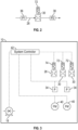
- FIG. 1 illustrated is an embodiment of a dual valve fluid flow metering system 10.
- the system 10 provides a fluid flow from an upstream fluid reservoir 12 or other fluid source, to a plurality of downstream consumers 14 or other users or uses of the fluid flow. While two downstream consumers 14 are illustrated in FIG. 1 and described herein, one skilled in the art will readily appreciate that other numbers of downstream consumers 14, such as one, three or more downstream consumers 14 may be serviced by the system 10.
- the fluid flow is drawn from the fluid reservoir 12 along an input line 16 by a pump 18.
- the pump 18 is a positive displacement pump operating at a fixed speed, while in other embodiments the pump 18 may be a variable speed pump.
- a recirculation line 20 connects a pump outlet 22 and a pump inlet 24.
- a pressure regulating valve 26 is located along the recirculation line 20.
- One or more fluid delivery lines 28 extend from the pump outlet 22 to the downstream consumers 14. In the embodiment shown in FIG. 1 , there are two downstream consumers 14, so there are two fluid delivery lines 28, with each fluid delivery line 28 connecting the pump outlet 22 to a respective downstream consumer 14.
- Each fluid delivery line 28 includes a fluid control valve 30 disposed along its length upstream of a fluid outlet 32 to the respective downstream consumer 14.
- the pressure regulating valve 26 and the flow control valves 30 are proportional solenoid valves, which may be identical or may be different sizes according to flow demands.
- a differential pressure sensor 34 measures a pressure drop across the fluid control valve 30.
- the pressure drop measurement may be obtained via a first pressure sensor 36 disposed upstream of the fluid control valve 30 and a second pressure sensor 38 disposed downstream of the fluid control valve 30.
- a flow meter 40 is disposed along each fluid delivery line 28 and measures a flow rate through the flow control valve 30.
- the flow meter 40 is located upstream of the flow control valve 30 such as shown in FIG. 1 , while in other embodiments the flow meter is located downstream of the flow control valve 30.
- a system controller 42 is operably connected to the components of the system 10, as shown in FIG. 3 .
- the system controller 42 is utilized to control the system 10 through two simultaneous feedback control loops.
- a first feedback loop utilizes the detected delta pressures from the delta pressure sensors 34 and adjusts a position of the pressure regulating valve 26 such that a delta pressure across the flow control valves 30 remains constant and reduces a range of required flow coefficient through the flow control valves 30.
- the fluid flow directed through the pressure regulating valve 26 is re-routed to the pump inlet 24 and/or to the reservoir 12.
- the flow through the pressure regulating valve 26 may also be passed through a heat exchanger 70 for cooling to prevent overheating of the fluid flow.
- a second feedback loop utilizes a sensed flow rate through the flow meters 40 and adjusts the flow control valves 30 to provide a selected flow rate to the downstream consumers 14.
- FIG. 4 An exemplary flow diagram of operation of the system 10, and more specifically the system controller 42, is illustrated in FIG. 4 .
- the system controller 42 receives a flow rate set point 44 command and a delta pressure set point 46 command.
- the flow rate set point 44 is compared to a measured flow rate 48 from the respective flow meter 40 and a resulting flow rate error 50 is used by a flow control valve controller 72 to determine a flow control valve command 52 to adjust the flow control valve 30 to provide a flow rate to match the selected flow rate set point 44.
- the flow control valve 30 is then adjusted according to the flow control valve command 52.
- the flow rate 48 is measured again by the flow meter 40 and compared to the flow rate set point 44.
- the flow control valves 30 are adjusted again until the flow rate set point 44 is reached.
- a pump speed may be actively varied based on the flow control valve command 52. This would reduce a turndown ratio burden on the flow control valves 30 by using the pump 18 to aid in controlling the flow rate, rather than solely relying on the flow control valves 30.
- the delta pressure set point 46 is compared to a minimum measured delta pressure 54 from the delta pressure sensors 34.
- the minimum measured delta pressure 54 is the lowest of the delta pressures measured by the delta pressure sensors 34 of each of the delta pressure sensors 34.
- a delta pressure error 56 is used by a pressure regulating valve controller 74 to determine a pressure regulating valve command 58 to adjust the pressure regulating valve 26 to provide a pressure drop to match the selected pressure drop set point 46.
- the pressure regulating valve 26 is then adjusted according to the pressure regulating valve command 58.
- the delta pressures are measured again, and a minimum measure delta pressure 54 is determined and compared to the delta pressure set point 46.
- the pressure regulating valve 26 is adjusted again until the delta pressure set point 46 is reached.
- the flow rate error 50 and the delta pressure error 56 are input into a multiple input multiple output (MIMO) error blending algorithm 60 to blend the flow rate error 50 and the delta pressure error 56 to improve stability by damping interaction between the two feedback loops.
- MIMO multiple input multiple output
- the pressure regulating valve In other fluid metering systems that utilize a pressure regulating valve and a flow control valve, the pressure regulating valve has a fixed pressure set point based on a maximum required delivery pressure under all operating conditions. This approach puts the burden of turndown ratio on the flow control valve to respond to changes in flow and back pressure (or pressure differential). It also requires that the pump always operates at the maximum pressure rise, which increases power consumption and fluid heating.
- the fast acting, electronically controlled pressure regulating valve 26 adapts to changes in delta pressure set point 46 and flow rate set point 44, thus reducing turndown ratio burden on the flow control valves 30 and reducing power consumption.
- the control system 42 controls both the pressure regulating valve 26 and the flow control valves 30 in tandem to meter the fluid flow.
Applications Claiming Priority (1)
| Application Number | Priority Date | Filing Date | Title |
|---|---|---|---|
| US17/490,082 US11713718B2 (en) | 2021-09-30 | 2021-09-30 | Dual valve fluid metering system |
Publications (1)
| Publication Number | Publication Date |
|---|---|
| EP4159991A1 true EP4159991A1 (fr) | 2023-04-05 |
Family
ID=82308485
Family Applications (1)
| Application Number | Title | Priority Date | Filing Date |
|---|---|---|---|
| EP22179271.6A Pending EP4159991A1 (fr) | 2021-09-30 | 2022-06-15 | Système de mesure de fluides à double soupape |
Country Status (3)
| Country | Link |
|---|---|
| US (1) | US11713718B2 (fr) |
| EP (1) | EP4159991A1 (fr) |
| CN (1) | CN115875137A (fr) |
Citations (4)
| Publication number | Priority date | Publication date | Assignee | Title |
|---|---|---|---|---|
| US20120042657A1 (en) * | 2009-04-29 | 2012-02-23 | Snecma | method and device for feeding a turbomachine combustion chamber with a regulated flow of fuel |
| US20160053689A1 (en) * | 2013-04-14 | 2016-02-25 | General Electric Company | Engine overspeed protection with thrust control |
| FR3053396A1 (fr) * | 2016-06-30 | 2018-01-05 | Safran Aircraft Engines | Dispositif de dosage de carburant et procede associe |
| US20180163637A1 (en) * | 2016-12-09 | 2018-06-14 | Rolls-Royce Plc | Fuel supply system |
Family Cites Families (15)
| Publication number | Priority date | Publication date | Assignee | Title |
|---|---|---|---|---|
| US6079198A (en) | 1998-04-29 | 2000-06-27 | General Electric Co. | Pressure compensated fuel delivery system for the combustors of turbomachinery |
| DE19848434C2 (de) * | 1998-10-21 | 2000-11-23 | Mtu Muenchen Gmbh | Brennstoffzumeßsystem |
| GB0206222D0 (en) * | 2002-03-15 | 2002-05-01 | Lucas Industries Ltd | Control system |
| BRPI0509387A (pt) * | 2004-03-29 | 2007-09-18 | Argo Tech Corp | bomba de deslocamento variável de configuração de deslocamento duplo utilizada como proteção contra propulsão excessiva de motor com benefìcio térmico de sistema de combustìvel |
| FR2882098B1 (fr) * | 2005-02-17 | 2011-07-15 | Hispano Suiza Sa | Regulation du debit de carburant alimentant un moteur a turbine a gaz |
| US8302406B2 (en) | 2008-10-15 | 2012-11-06 | Woodward, Inc. | Fuel delivery and control system including a positive displacement actuation pump with a variable pressure regulator supplementing a fixed displacement main fuel pump |
| US8276360B2 (en) | 2009-05-22 | 2012-10-02 | Hamilton Sundstrand Corporation | Dual-pump fuel system and method for starting a gas turbine engine |
| US8523537B2 (en) | 2010-08-23 | 2013-09-03 | Woodward, Inc. | Integral plus proportional dual pump switching system |
| US8919094B2 (en) | 2012-04-24 | 2014-12-30 | Hamilton Sundstrand Corporation | Fuel metering system |
| US9334840B2 (en) | 2013-07-19 | 2016-05-10 | Woodward, Inc. | Series plus parallel metering pressure regulation system for a thermal efficient fuel metering system |
| CN105874186B (zh) | 2013-11-20 | 2018-12-18 | 伍德沃德公司 | 具有集成的流量计放置的并联计量压力调节系统及其测量方法 |
| US10975776B2 (en) * | 2016-04-07 | 2021-04-13 | Raytheon Technologies Corporation | Adaptive fuel flow estimation with flow meter feedback |
| US20180157279A1 (en) * | 2016-12-02 | 2018-06-07 | RAM Manufacturing Company, Inc. | Electronic Fluid Metering Valve |
| FR3068114B1 (fr) * | 2017-06-27 | 2019-08-16 | Safran Aircraft Engines | Systeme d'alimentation en fluide pour turbomachine, comprenant une pompe a cylindree variable suivie d'un doseur de fluide |
| US11629652B2 (en) | 2020-02-05 | 2023-04-18 | Hamilton Sundstrand Corporation | Metering pump system |
-
2021
- 2021-09-30 US US17/490,082 patent/US11713718B2/en active Active
-
2022
- 2022-06-15 EP EP22179271.6A patent/EP4159991A1/fr active Pending
- 2022-07-29 CN CN202210909037.0A patent/CN115875137A/zh active Pending
Patent Citations (4)
| Publication number | Priority date | Publication date | Assignee | Title |
|---|---|---|---|---|
| US20120042657A1 (en) * | 2009-04-29 | 2012-02-23 | Snecma | method and device for feeding a turbomachine combustion chamber with a regulated flow of fuel |
| US20160053689A1 (en) * | 2013-04-14 | 2016-02-25 | General Electric Company | Engine overspeed protection with thrust control |
| FR3053396A1 (fr) * | 2016-06-30 | 2018-01-05 | Safran Aircraft Engines | Dispositif de dosage de carburant et procede associe |
| US20180163637A1 (en) * | 2016-12-09 | 2018-06-14 | Rolls-Royce Plc | Fuel supply system |
Also Published As
| Publication number | Publication date |
|---|---|
| CN115875137A (zh) | 2023-03-31 |
| US20230101637A1 (en) | 2023-03-30 |
| US11713718B2 (en) | 2023-08-01 |
Similar Documents
| Publication | Publication Date | Title |
|---|---|---|
| CN107883399B (zh) | 调节紊流流动 | |
| US9574448B2 (en) | Split control unit | |
| CN105318772B (zh) | 用于在传热系统中限制供给通量的方法 | |
| US6644039B2 (en) | Delivery system for liquefied gas with maintained delivery tank pressure | |
| US10900421B2 (en) | Direct feedback regarding metered flow of fuel system | |
| CN104654448A (zh) | 用于传热系统的控制方法以及这种传热系统 | |
| KR20070037319A (ko) | 항온액 순환장치 및 상기 장치에 있어서의 온도제어방법 | |
| US4798531A (en) | Process and apparatus for the control of the air and fuel supply to a plurality of burners | |
| KR20060047881A (ko) | 액화 가스 운반용 선박의 에너지 생성 유닛에 가스 연료를공급하는 설비 | |
| JP6253357B2 (ja) | ハイドロスタティック式の駆動システム | |
| CN106715882B (zh) | 燃料消耗测量系统以及用于测量内燃机的燃料消耗的方法 | |
| US20200217284A1 (en) | Pressure-regulating device for a fuel consumption measurement system and fuel consumption measurement system | |
| US4591317A (en) | Dual pump controls | |
| EP2025901B1 (fr) | Système de dosage de carburant avec une introduction de chaleur minimale | |
| US7080503B2 (en) | Control system | |
| EP4159991A1 (fr) | Système de mesure de fluides à double soupape | |
| EP4063654A2 (fr) | Pompe à cylindrée variable avec commande par rétroaction de dérivation active | |
| KR20200142017A (ko) | 기체나 액체를 일정한 목표 온도로 조절하기 위한 컨디셔닝 장치 | |
| WO2019084339A1 (fr) | Régulateur de débit à large plage, à faible taux de décroissance de débit et à détermination de température | |
| US11300982B2 (en) | System and method for the metering of a liquid or gaseous medium | |
| US20130019956A1 (en) | Constant flow rate fluid controller | |
| EP4194762A1 (fr) | Procédé de réglage d'une température d'alimentation souhaitée dans un système de transfert de chaleur et système de transfert de chaleur | |
| CN109563985A (zh) | 用于操作废热蒸汽发生器的方法 | |
| KR20230009823A (ko) | 유체 분배 네트워크의 섹터에서 열 에너지 운반 유체의 온도를 조절하기 위한 시스템 | |
| JPS649527B2 (fr) |
Legal Events
| Date | Code | Title | Description |
|---|---|---|---|
| PUAI | Public reference made under article 153(3) epc to a published international application that has entered the european phase |
Free format text: ORIGINAL CODE: 0009012 |
|
| STAA | Information on the status of an ep patent application or granted ep patent |
Free format text: STATUS: THE APPLICATION HAS BEEN PUBLISHED |
|
| AK | Designated contracting states |
Kind code of ref document: A1 Designated state(s): AL AT BE BG CH CY CZ DE DK EE ES FI FR GB GR HR HU IE IS IT LI LT LU LV MC MK MT NL NO PL PT RO RS SE SI SK SM TR |
|
| STAA | Information on the status of an ep patent application or granted ep patent |
Free format text: STATUS: REQUEST FOR EXAMINATION WAS MADE |
|
| 17P | Request for examination filed |
Effective date: 20231002 |
|
| RBV | Designated contracting states (corrected) |
Designated state(s): AL AT BE BG CH CY CZ DE DK EE ES FI FR GB GR HR HU IE IS IT LI LT LU LV MC MK MT NL NO PL PT RO RS SE SI SK SM TR |
|
| STAA | Information on the status of an ep patent application or granted ep patent |
Free format text: STATUS: EXAMINATION IS IN PROGRESS |
|
| 17Q | First examination report despatched |
Effective date: 20240405 |