EP4159986B1 - Dispositif de post-traitement des gaz d'échappement et système de post-traitement des gaz d'échappement d'un moteur à combustion interne - Google Patents
Dispositif de post-traitement des gaz d'échappement et système de post-traitement des gaz d'échappement d'un moteur à combustion interne Download PDFInfo
- Publication number
- EP4159986B1 EP4159986B1 EP22198984.1A EP22198984A EP4159986B1 EP 4159986 B1 EP4159986 B1 EP 4159986B1 EP 22198984 A EP22198984 A EP 22198984A EP 4159986 B1 EP4159986 B1 EP 4159986B1
- Authority
- EP
- European Patent Office
- Prior art keywords
- exhaust gas
- flow direction
- treatment unit
- preload
- treatment
- Prior art date
- Legal status (The legal status is an assumption and is not a legal conclusion. Google has not performed a legal analysis and makes no representation as to the accuracy of the status listed.)
- Active
Links
Images


Classifications
-
- F—MECHANICAL ENGINEERING; LIGHTING; HEATING; WEAPONS; BLASTING
- F01—MACHINES OR ENGINES IN GENERAL; ENGINE PLANTS IN GENERAL; STEAM ENGINES
- F01N—GAS-FLOW SILENCERS OR EXHAUST APPARATUS FOR MACHINES OR ENGINES IN GENERAL; GAS-FLOW SILENCERS OR EXHAUST APPARATUS FOR INTERNAL-COMBUSTION ENGINES
- F01N3/00—Exhaust or silencing apparatus having means for purifying, rendering innocuous, or otherwise treating exhaust
- F01N3/08—Exhaust or silencing apparatus having means for purifying, rendering innocuous, or otherwise treating exhaust for rendering innocuous
- F01N3/10—Exhaust or silencing apparatus having means for purifying, rendering innocuous, or otherwise treating exhaust for rendering innocuous by thermal or catalytic conversion of noxious components of exhaust
- F01N3/24—Exhaust or silencing apparatus having means for purifying, rendering innocuous, or otherwise treating exhaust for rendering innocuous by thermal or catalytic conversion of noxious components of exhaust characterised by constructional aspects of converting apparatus
- F01N3/28—Construction of catalytic reactors
- F01N3/2839—Arrangements for mounting catalyst support in housing, e.g. with means for compensating thermal expansion or vibration
- F01N3/2842—Arrangements for mounting catalyst support in housing, e.g. with means for compensating thermal expansion or vibration specially adapted for monolithic supports, e.g. of honeycomb type
-
- F—MECHANICAL ENGINEERING; LIGHTING; HEATING; WEAPONS; BLASTING
- F01—MACHINES OR ENGINES IN GENERAL; ENGINE PLANTS IN GENERAL; STEAM ENGINES
- F01N—GAS-FLOW SILENCERS OR EXHAUST APPARATUS FOR MACHINES OR ENGINES IN GENERAL; GAS-FLOW SILENCERS OR EXHAUST APPARATUS FOR INTERNAL-COMBUSTION ENGINES
- F01N13/00—Exhaust or silencing apparatus characterised by constructional features
- F01N13/18—Construction facilitating manufacture, assembly, or disassembly
- F01N13/1805—Fixing exhaust manifolds, exhaust pipes or pipe sections to each other, to engine or to vehicle body
- F01N13/1811—Fixing exhaust manifolds, exhaust pipes or pipe sections to each other, to engine or to vehicle body with means permitting relative movement, e.g. compensation of thermal expansion or vibration
- F01N13/1816—Fixing exhaust manifolds, exhaust pipes or pipe sections to each other, to engine or to vehicle body with means permitting relative movement, e.g. compensation of thermal expansion or vibration the pipe sections being joined together by flexible tubular elements only, e.g. using bellows or strip-wound pipes
-
- F—MECHANICAL ENGINEERING; LIGHTING; HEATING; WEAPONS; BLASTING
- F01—MACHINES OR ENGINES IN GENERAL; ENGINE PLANTS IN GENERAL; STEAM ENGINES
- F01N—GAS-FLOW SILENCERS OR EXHAUST APPARATUS FOR MACHINES OR ENGINES IN GENERAL; GAS-FLOW SILENCERS OR EXHAUST APPARATUS FOR INTERNAL-COMBUSTION ENGINES
- F01N3/00—Exhaust or silencing apparatus having means for purifying, rendering innocuous, or otherwise treating exhaust
- F01N3/02—Exhaust or silencing apparatus having means for purifying, rendering innocuous, or otherwise treating exhaust for cooling, or for removing solid constituents of, exhaust
- F01N3/021—Exhaust or silencing apparatus having means for purifying, rendering innocuous, or otherwise treating exhaust for cooling, or for removing solid constituents of, exhaust by means of filters
-
- F—MECHANICAL ENGINEERING; LIGHTING; HEATING; WEAPONS; BLASTING
- F01—MACHINES OR ENGINES IN GENERAL; ENGINE PLANTS IN GENERAL; STEAM ENGINES
- F01N—GAS-FLOW SILENCERS OR EXHAUST APPARATUS FOR MACHINES OR ENGINES IN GENERAL; GAS-FLOW SILENCERS OR EXHAUST APPARATUS FOR INTERNAL-COMBUSTION ENGINES
- F01N3/00—Exhaust or silencing apparatus having means for purifying, rendering innocuous, or otherwise treating exhaust
- F01N3/08—Exhaust or silencing apparatus having means for purifying, rendering innocuous, or otherwise treating exhaust for rendering innocuous
- F01N3/10—Exhaust or silencing apparatus having means for purifying, rendering innocuous, or otherwise treating exhaust for rendering innocuous by thermal or catalytic conversion of noxious components of exhaust
- F01N3/24—Exhaust or silencing apparatus having means for purifying, rendering innocuous, or otherwise treating exhaust for rendering innocuous by thermal or catalytic conversion of noxious components of exhaust characterised by constructional aspects of converting apparatus
- F01N3/28—Construction of catalytic reactors
- F01N3/2839—Arrangements for mounting catalyst support in housing, e.g. with means for compensating thermal expansion or vibration
- F01N3/2853—Arrangements for mounting catalyst support in housing, e.g. with means for compensating thermal expansion or vibration using mats or gaskets between catalyst body and housing
- F01N3/2867—Arrangements for mounting catalyst support in housing, e.g. with means for compensating thermal expansion or vibration using mats or gaskets between catalyst body and housing the mats or gaskets being placed at the front or end face of catalyst body
-
- F—MECHANICAL ENGINEERING; LIGHTING; HEATING; WEAPONS; BLASTING
- F01—MACHINES OR ENGINES IN GENERAL; ENGINE PLANTS IN GENERAL; STEAM ENGINES
- F01N—GAS-FLOW SILENCERS OR EXHAUST APPARATUS FOR MACHINES OR ENGINES IN GENERAL; GAS-FLOW SILENCERS OR EXHAUST APPARATUS FOR INTERNAL-COMBUSTION ENGINES
- F01N3/00—Exhaust or silencing apparatus having means for purifying, rendering innocuous, or otherwise treating exhaust
- F01N3/08—Exhaust or silencing apparatus having means for purifying, rendering innocuous, or otherwise treating exhaust for rendering innocuous
- F01N3/10—Exhaust or silencing apparatus having means for purifying, rendering innocuous, or otherwise treating exhaust for rendering innocuous by thermal or catalytic conversion of noxious components of exhaust
- F01N3/24—Exhaust or silencing apparatus having means for purifying, rendering innocuous, or otherwise treating exhaust for rendering innocuous by thermal or catalytic conversion of noxious components of exhaust characterised by constructional aspects of converting apparatus
- F01N3/28—Construction of catalytic reactors
- F01N3/2839—Arrangements for mounting catalyst support in housing, e.g. with means for compensating thermal expansion or vibration
- F01N3/2875—Arrangements for mounting catalyst support in housing, e.g. with means for compensating thermal expansion or vibration by using elastic means, e.g. spring leaves, for retaining catalyst body in the housing
-
- F—MECHANICAL ENGINEERING; LIGHTING; HEATING; WEAPONS; BLASTING
- F01—MACHINES OR ENGINES IN GENERAL; ENGINE PLANTS IN GENERAL; STEAM ENGINES
- F01N—GAS-FLOW SILENCERS OR EXHAUST APPARATUS FOR MACHINES OR ENGINES IN GENERAL; GAS-FLOW SILENCERS OR EXHAUST APPARATUS FOR INTERNAL-COMBUSTION ENGINES
- F01N13/00—Exhaust or silencing apparatus characterised by constructional features
- F01N13/18—Construction facilitating manufacture, assembly, or disassembly
- F01N13/1872—Construction facilitating manufacture, assembly, or disassembly the assembly using stamp-formed parts or otherwise deformed sheet-metal
-
- F—MECHANICAL ENGINEERING; LIGHTING; HEATING; WEAPONS; BLASTING
- F01—MACHINES OR ENGINES IN GENERAL; ENGINE PLANTS IN GENERAL; STEAM ENGINES
- F01N—GAS-FLOW SILENCERS OR EXHAUST APPARATUS FOR MACHINES OR ENGINES IN GENERAL; GAS-FLOW SILENCERS OR EXHAUST APPARATUS FOR INTERNAL-COMBUSTION ENGINES
- F01N2330/00—Structure of catalyst support or particle filter
- F01N2330/06—Ceramic, e.g. monoliths
-
- F—MECHANICAL ENGINEERING; LIGHTING; HEATING; WEAPONS; BLASTING
- F01—MACHINES OR ENGINES IN GENERAL; ENGINE PLANTS IN GENERAL; STEAM ENGINES
- F01N—GAS-FLOW SILENCERS OR EXHAUST APPARATUS FOR MACHINES OR ENGINES IN GENERAL; GAS-FLOW SILENCERS OR EXHAUST APPARATUS FOR INTERNAL-COMBUSTION ENGINES
- F01N2350/00—Arrangements for fitting catalyst support or particle filter element in the housing
- F01N2350/02—Fitting ceramic monoliths in a metallic housing
- F01N2350/04—Fitting ceramic monoliths in a metallic housing with means compensating thermal expansion
-
- F—MECHANICAL ENGINEERING; LIGHTING; HEATING; WEAPONS; BLASTING
- F01—MACHINES OR ENGINES IN GENERAL; ENGINE PLANTS IN GENERAL; STEAM ENGINES
- F01N—GAS-FLOW SILENCERS OR EXHAUST APPARATUS FOR MACHINES OR ENGINES IN GENERAL; GAS-FLOW SILENCERS OR EXHAUST APPARATUS FOR INTERNAL-COMBUSTION ENGINES
- F01N2450/00—Methods or apparatus for fitting, inserting or repairing different elements
- F01N2450/18—Methods or apparatus for fitting, inserting or repairing different elements by using quick-active type locking mechanisms, e.g. clips
-
- F—MECHANICAL ENGINEERING; LIGHTING; HEATING; WEAPONS; BLASTING
- F01—MACHINES OR ENGINES IN GENERAL; ENGINE PLANTS IN GENERAL; STEAM ENGINES
- F01N—GAS-FLOW SILENCERS OR EXHAUST APPARATUS FOR MACHINES OR ENGINES IN GENERAL; GAS-FLOW SILENCERS OR EXHAUST APPARATUS FOR INTERNAL-COMBUSTION ENGINES
- F01N2450/00—Methods or apparatus for fitting, inserting or repairing different elements
- F01N2450/30—Removable or rechangeable blocks or cartridges, e.g. for filters
-
- F—MECHANICAL ENGINEERING; LIGHTING; HEATING; WEAPONS; BLASTING
- F01—MACHINES OR ENGINES IN GENERAL; ENGINE PLANTS IN GENERAL; STEAM ENGINES
- F01N—GAS-FLOW SILENCERS OR EXHAUST APPARATUS FOR MACHINES OR ENGINES IN GENERAL; GAS-FLOW SILENCERS OR EXHAUST APPARATUS FOR INTERNAL-COMBUSTION ENGINES
- F01N2470/00—Structure or shape of exhaust gas passages, pipes or tubes
- F01N2470/12—Tubes being corrugated
-
- F—MECHANICAL ENGINEERING; LIGHTING; HEATING; WEAPONS; BLASTING
- F01—MACHINES OR ENGINES IN GENERAL; ENGINE PLANTS IN GENERAL; STEAM ENGINES
- F01N—GAS-FLOW SILENCERS OR EXHAUST APPARATUS FOR MACHINES OR ENGINES IN GENERAL; GAS-FLOW SILENCERS OR EXHAUST APPARATUS FOR INTERNAL-COMBUSTION ENGINES
- F01N2590/00—Exhaust or silencing apparatus adapted to particular use, e.g. for military applications, airplanes, submarines
- F01N2590/02—Exhaust or silencing apparatus adapted to particular use, e.g. for military applications, airplanes, submarines for marine vessels or naval applications
-
- F—MECHANICAL ENGINEERING; LIGHTING; HEATING; WEAPONS; BLASTING
- F01—MACHINES OR ENGINES IN GENERAL; ENGINE PLANTS IN GENERAL; STEAM ENGINES
- F01N—GAS-FLOW SILENCERS OR EXHAUST APPARATUS FOR MACHINES OR ENGINES IN GENERAL; GAS-FLOW SILENCERS OR EXHAUST APPARATUS FOR INTERNAL-COMBUSTION ENGINES
- F01N2590/00—Exhaust or silencing apparatus adapted to particular use, e.g. for military applications, airplanes, submarines
- F01N2590/08—Exhaust or silencing apparatus adapted to particular use, e.g. for military applications, airplanes, submarines for heavy duty applications, e.g. trucks, buses, tractors, locomotives
-
- F—MECHANICAL ENGINEERING; LIGHTING; HEATING; WEAPONS; BLASTING
- F01—MACHINES OR ENGINES IN GENERAL; ENGINE PLANTS IN GENERAL; STEAM ENGINES
- F01N—GAS-FLOW SILENCERS OR EXHAUST APPARATUS FOR MACHINES OR ENGINES IN GENERAL; GAS-FLOW SILENCERS OR EXHAUST APPARATUS FOR INTERNAL-COMBUSTION ENGINES
- F01N2590/00—Exhaust or silencing apparatus adapted to particular use, e.g. for military applications, airplanes, submarines
- F01N2590/10—Exhaust or silencing apparatus adapted to particular use, e.g. for military applications, airplanes, submarines for stationary applications
-
- F—MECHANICAL ENGINEERING; LIGHTING; HEATING; WEAPONS; BLASTING
- F01—MACHINES OR ENGINES IN GENERAL; ENGINE PLANTS IN GENERAL; STEAM ENGINES
- F01N—GAS-FLOW SILENCERS OR EXHAUST APPARATUS FOR MACHINES OR ENGINES IN GENERAL; GAS-FLOW SILENCERS OR EXHAUST APPARATUS FOR INTERNAL-COMBUSTION ENGINES
- F01N3/00—Exhaust or silencing apparatus having means for purifying, rendering innocuous, or otherwise treating exhaust
- F01N3/02—Exhaust or silencing apparatus having means for purifying, rendering innocuous, or otherwise treating exhaust for cooling, or for removing solid constituents of, exhaust
- F01N3/021—Exhaust or silencing apparatus having means for purifying, rendering innocuous, or otherwise treating exhaust for cooling, or for removing solid constituents of, exhaust by means of filters
- F01N3/0211—Arrangements for mounting filtering elements in housing, e.g. with means for compensating thermal expansion or vibration
-
- F—MECHANICAL ENGINEERING; LIGHTING; HEATING; WEAPONS; BLASTING
- F01—MACHINES OR ENGINES IN GENERAL; ENGINE PLANTS IN GENERAL; STEAM ENGINES
- F01N—GAS-FLOW SILENCERS OR EXHAUST APPARATUS FOR MACHINES OR ENGINES IN GENERAL; GAS-FLOW SILENCERS OR EXHAUST APPARATUS FOR INTERNAL-COMBUSTION ENGINES
- F01N3/00—Exhaust or silencing apparatus having means for purifying, rendering innocuous, or otherwise treating exhaust
- F01N3/08—Exhaust or silencing apparatus having means for purifying, rendering innocuous, or otherwise treating exhaust for rendering innocuous
- F01N3/10—Exhaust or silencing apparatus having means for purifying, rendering innocuous, or otherwise treating exhaust for rendering innocuous by thermal or catalytic conversion of noxious components of exhaust
- F01N3/24—Exhaust or silencing apparatus having means for purifying, rendering innocuous, or otherwise treating exhaust for rendering innocuous by thermal or catalytic conversion of noxious components of exhaust characterised by constructional aspects of converting apparatus
- F01N3/28—Construction of catalytic reactors
- F01N3/2839—Arrangements for mounting catalyst support in housing, e.g. with means for compensating thermal expansion or vibration
- F01N3/2853—Arrangements for mounting catalyst support in housing, e.g. with means for compensating thermal expansion or vibration using mats or gaskets between catalyst body and housing
-
- Y—GENERAL TAGGING OF NEW TECHNOLOGICAL DEVELOPMENTS; GENERAL TAGGING OF CROSS-SECTIONAL TECHNOLOGIES SPANNING OVER SEVERAL SECTIONS OF THE IPC; TECHNICAL SUBJECTS COVERED BY FORMER USPC CROSS-REFERENCE ART COLLECTIONS [XRACs] AND DIGESTS
- Y02—TECHNOLOGIES OR APPLICATIONS FOR MITIGATION OR ADAPTATION AGAINST CLIMATE CHANGE
- Y02T—CLIMATE CHANGE MITIGATION TECHNOLOGIES RELATED TO TRANSPORTATION
- Y02T10/00—Road transport of goods or passengers
- Y02T10/10—Internal combustion engine [ICE] based vehicles
- Y02T10/12—Improving ICE efficiencies
Definitions
- the invention relates to an exhaust gas aftertreatment system of an internal combustion engine according to the preamble of claim 1.
- the present invention relates to the field of so-called large internal combustion engines, whose cylinders have piston diameters of at least 140 mm, in particular of at least 175 mm.
- large internal combustion engines include, for example, marine engines.
- Such large internal combustion engines can be designed as diesel engines, gas engines, or dual-fuel engines. In dual-fuel engines, a liquid fuel, in particular a diesel fuel, can be burned in a first operating state, and a gaseous fuel, in particular natural gas, can be burned in a second operating state.
- Exhaust gas aftertreatment is also playing an increasingly important role in the field of large combustion engines.
- the exhaust gas aftertreatment system disclosed therein has a reactor chamber, with an SCR catalyst arranged in the reactor chamber. It is known that such an SCR catalyst has several exhaust gas aftertreatment units connected in parallel, through which exhaust gas flows, wherein each exhaust gas aftertreatment unit has a honeycomb body that is held by a honeycomb body carrier and is arranged in a receiving housing via the honeycomb body carrier.
- the honeycomb body carrier is also referred to as a canning, which surrounds the respective honeycomb body on the outside, leaving its end faces free.
- EP 3 147 472 A1 discloses an exhaust aftertreatment system of an internal combustion engine according to the preamble of claim 1.
- the invention is based on the object of creating a novel exhaust gas aftertreatment system for an internal combustion engine.
- the preloading elements acting in the flow direction and perpendicular to the flow direction of the respective exhaust aftertreatment unit ensure that the exhaust gas is guided through the at least one honeycomb body of the at least one exhaust aftertreatment unit and does not flow past the honeycomb body via gaps between the honeycomb body support of the respective honeycomb body and the receiving housing. This can be achieved with minimal effort using the first preloading elements acting in the flow direction of the respective exhaust aftertreatment unit and the second preloading elements acting perpendicular to the flow direction of the respective exhaust aftertreatment unit.
- the first prestressing elements acting in the flow direction of the respective exhaust gas aftertreatment unit and the second prestressing elements acting perpendicular to the flow direction of the respective exhaust gas aftertreatment unit are formed by separate prestressing assemblies, wherein each separate prestressing assembly has a first prestressing element acting in the flow direction of the respective exhaust gas aftertreatment unit and a plurality of second prestressing elements acting perpendicular to the flow direction of the respective exhaust gas aftertreatment unit, and wherein the separate prestressing assemblies are plugged onto the respective exhaust gas aftertreatment unit at at least one of opposite axial ends of the same, namely onto the honeycomb body carrier of the respective exhaust gas aftertreatment unit.
- the prestressing elements are formed by separate prestressing assemblies that are plugged onto the respective exhaust gas aftertreatment unit, the prestressing assemblies can be reused, in particular if an exhaust gas aftertreatment unit has to be replaced, for example as a result of a blocked honeycomb body.
- the first prestressing elements acting in the flow direction of the respective exhaust gas aftertreatment unit are designed as bellows-like prestressing elements.
- the prestressing of the respective exhaust gas aftertreatment unit in the flow direction of the respective exhaust gas aftertreatment unit can be provided simply and advantageously via bellows-like prestressing elements.
- the second prestressing elements acting perpendicular to the flow direction of the respective exhaust gas aftertreatment unit are designed as latch-like projections.
- the prestressing of the respective exhaust gas aftertreatment unit perpendicular to the flow direction of the respective exhaust gas aftertreatment unit can be provided simply and reliably via latch-like projections.
- the pawl-like projections form an angle of 90° with the flow direction.
- the respective exhaust gas aftertreatment unit can be arranged particularly advantageously in the receiving housing together with the preloading elements.
- sealing surfaces on the first preloading elements acting in the flow direction of the respective exhaust aftertreatment unit are aligned perpendicular to the flow direction of the respective exhaust aftertreatment unit. This is particularly advantageous when multiple exhaust aftertreatment units are arranged one behind the other in a series connection in a receiving housing. In this case, a manufacturing tolerance in the area of the exhaust aftertreatment unit ensures that the sealing effect on the sealing surfaces is not impaired.
- the invention relates to an exhaust aftertreatment system for an internal combustion engine, in particular a large internal combustion engine.
- a large internal combustion engine is, in particular, a marine engine, which can be configured as a diesel engine, a gas engine, or a dual-fuel engine.
- a large internal combustion engine has cylinders with a piston diameter of at least 140 mm, in particular of at least 175 mm.
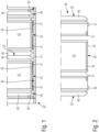
- Fig. 1 shows details of an exhaust gas aftertreatment device 40 not according to the invention.
- the exhaust gas aftertreatment device 40 has a receiving housing 41 and, in the example shown, a plurality of exhaust gas aftertreatment units 42 arranged in the receiving housing 41.
- a plurality of exhaust gas aftertreatment units 42 arranged in the receiving housing 41.
- two exhaust aftertreatment units 42 connected in series are shown, both of which are arranged in the receiving housing 41.
- the receiving housing 41 is in Fig. 1, 2 tubular in design.
- a flow direction through the receiving housing 41 or the exhaust aftertreatment units 42 arranged in the receiving housing 41 extends in the axial direction thereof. If the tubular receiving housing 41 and the exhaust aftertreatment units 42 arranged in the receiving housing 41 are circular in cross-section, the radial direction of the receiving housing 41 or the exhaust aftertreatment units 42 arranged in the receiving housing 41 extends perpendicular to the flow direction thereof.
- the cross sections of the receiving housing 41 and the exhaust aftertreatment units 42 can also be rectangular, square, oval, or the like.
- Each exhaust gas aftertreatment unit 42 has a honeycomb body 43 serving as a catalyst and/or particulate filter, as well as a honeycomb body support 44 surrounding the honeycomb body 43 on the outside and leaving the honeycomb body 43 free at the end faces thereof.
- the honeycomb body support 44 is also referred to as a canning.
- a fiber mat 45 is arranged between the honeycomb body 43 and the honeycomb support 44 of the exhaust aftertreatment units 42 shown there. The fiber mat 45 also leaves the end faces of the respective honeycomb body 43, which define an inlet side and an outlet side for the exhaust gas, exposed.
- the respective exhaust gas aftertreatment unit 43 is pre-tensioned in the receiving housing 41 via pre-tensioning elements.
- the respective exhaust gas aftertreatment unit 42 is positioned in the receiving housing 41 in a prestressed manner both via first prestressing elements 46 acting in the flow direction of the exhaust gas aftertreatment unit 42 and via second prestressing elements 47 acting perpendicular to the flow direction of the respective exhaust gas aftertreatment unit 42.
- the prestressing elements 46, 47 effect a spring-elastic prestress of the respective exhaust gas aftertreatment unit. 42 in the receiving housing 41 in the flow direction and perpendicular to the flow direction.
- the first prestressing elements 46 acting in the flow direction or in the axial direction of the respective exhaust gas aftertreatment unit 42 and the second prestressing elements 47 acting perpendicular to the flow direction or in the radial direction of the respective exhaust gas aftertreatment unit 42 are formed by separate prestressing assemblies 48.
- Each separate prestressing assembly 48 has a first prestressing element 46 acting in the flow direction of the respective exhaust gas aftertreatment unit 42 and a plurality of second prestressing elements 47 acting perpendicular to the flow direction of the respective exhaust gas aftertreatment unit 42.
- the separate preload assemblies 48 are in Fig. 1, 2 at opposite axial ends of the respective exhaust gas aftertreatment unit 42, namely on the honeycomb body support 44 of the respective exhaust gas aftertreatment unit 42, again leaving free the end faces of the respective honeycomb body 43, which serve as the inlet side and the outlet side of the respective honeycomb body 43 and thus of the respective exhaust gas aftertreatment unit 42 for the exhaust gas to be cleaned.
- the receiving housing 41 has a circular cross-section as viewed in the flow direction
- the exhaust aftertreatment units 42 and the separate preload assemblies 48 also have a circular cross-section.
- a plurality of second preload elements 47 which then serve to preload in the radial direction, are distributed around the circumference of the preload elements 48.
- the cross-sectional contour of the receiving housing 41 and the exhaust aftertreatment units 42 can also be rectangular, square, oval or the like.
- the first prestressing elements 46 acting in the flow direction of the respective exhaust gas aftertreatment unit 42 are designed as bellows-like prestressing elements.
- the second prestressing elements 47 which act perpendicular to the flow direction of the respective exhaust aftertreatment unit 42, are designed as pawl-like projections that are bent radially outward from the respective prestressing assembly 48. These second prestressing elements 47, preferably designed as pawl-like projections, are supported on an inner wall 49 of the receiving housing 41.
- the first prestressing elements 46 which act in the flow direction of the respective exhaust gas aftertreatment unit 42 and are preferably designed as bellows, are supported on an adjacent first prestressing element 46 of the adjacent exhaust gas aftertreatment unit 42 when a further exhaust gas aftertreatment unit 42 is connected to an exhaust gas aftertreatment unit 42. Otherwise, these first prestressing elements 46, which are designed like bellows, are supported on a radially inwardly extending projection 50 of the receiving housing 41.
- Fig. 2 can be removed, not only the outwardly projecting second pre-tensioning elements 47 are formed on the separate pre-tensioning assemblies 48, but also radially inwardly projecting third pre-tensioning elements 51. These radially inwardly projecting third pre-tensioning elements 51 serve to pre-tension the exhaust gas after-treatment unit 42 in the separate pre-tensioning assemblies 48. These radially inwardly projecting Preloading elements 51 are therefore supported elastically on the honeycomb support 44 of the respective exhaust gas aftertreatment unit 42.
- Sealing surfaces 52 on the first prestressing elements 46 acting in the flow direction run perpendicular to the flow direction of the respective exhaust gas aftertreatment unit 42. This is advantageous in order to avoid manufacturing tolerances in the area of the exhaust gas aftertreatment units 42 impairing the sealing effect between adjacent first prestressing elements 46 of adjacent exhaust gas aftertreatment units 42.
- Fig. 3 shows a partial cross-section through a further exhaust gas aftertreatment device 53 not according to the invention, which, with regard to its basic structure, is similar to the exhaust gas aftertreatment device 40 of the Fig. 1 Therefore, the same reference numbers are used for the same components and the following descriptions are made with reference to Fig. 3 details have been discussed which distinguish the exhaust gas aftertreatment device 53 of the Fig. 3 from the exhaust aftertreatment unit 40 of the Fig. 1 While in Fig. 1 the first biasing elements 46 and the second biasing elements 47 are both provided by separate biasing assemblies 48, are in Fig. 3 Both the first preload elements 46 and the second preload elements 47 are designed as an integral component of the honeycomb support 44 and thus of the canning. Although this reduces the number of individual assemblies, the preload elements 46, 47 cannot be reused when an exhaust aftertreatment unit 42 is replaced.
- Fig. 4 which is a detail of the Fig. 3 in the region of the adjacent first prestressing elements 46 of the adjacent exhaust gas aftertreatment units 42, it can be seen that the sealing surfaces 52 of the first prestressing elements 46 run perpendicular to the flow direction of the exhaust gas aftertreatment units 42.
- Fig. 5 a variation for the detail of the Fig. 4 , in which the sealing surfaces 52 of the adjacent first prestressing elements 46 of adjacent exhaust gas aftertreatment units 42 do not run perpendicular to the flow direction of the respective exhaust gas aftertreatment units 42, but rather are inclined with respect to the radial direction, which runs perpendicular to the flow direction.
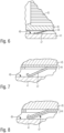
- Fig. 6 to 11 show details and possible designs of the second prestressing elements 47.
- the second prestressing element 47 shown there is again an integral part of the honeycomb support 44 or the canning, wherein both the honeycomb support 44 and the second prestressing element 47, which is designed as a latch-like projection, are each single-walled.
- Fig. 7 a configuration in which the honeycomb support 44 is multi-walled, namely double-walled, and the second prestressing element 47, which is designed as a latch-like projection, is single-walled.
- Fig. 8 which shows a further modification, both the honeycomb support 44 and the second prestressing element 47 shown are each multi-walled.
- the variants shown have the variant of the Fig. 7 the advantage that the fiber mat 45 is supported over its entire axial extent by the honeycomb receiving body 44 and, moreover, the second prestressing element 47 can be easily formed.
- Figs. 6, 7 and 8 refer to second prestressing elements 47, which are designed as an integral part of the honeycomb carrier 44, it should be noted that the variants of the Figs. 6, 7 and 8 also in the exhaust aftertreatment device 40 of the Fig. 1 can be used.
- the single-wall or multi-wall design does not refer to the honeycomb support 44, but rather to the separate prestressing assemblies 46, which provide the prestressing elements 46 and 47.
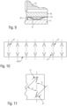
- Fig. 9 shows a modification of the Fig. 6 , in which the second prestressing element 47 shown there is single-walled and designed in the shape of a bridge. This is again an integral part of the honeycomb carrier 44. Also in Fig. 9 The multi-walled nature of the Figs. 7 and 8 can also be used in Fig. 1, 2 a second prestressing element 47 may be designed in bridge form.
- Fig. 10 shows a development of either a separate prestressing assembly 48 or a honeycomb carrier 44 in the region of second prestressing elements 47.
- the second pre-tensioning elements 47 are shown, which are projected radially outwards and, in the installed state, come into contact with the inner surface 49 of the receiving housing 41.
- these second pre-tensioning elements 47 are preferably blade-like projections, wherein these pawl-like projections enclose an angle ⁇ or an angle ⁇ with the flow direction of the respective exhaust gas aftertreatment unit 42.
- the second pre-tensioning elements 47 enclose the angle ⁇ and in the area of the outlet-side end, the second pre-tensioning elements 47 enclose the angle ⁇ with the flow direction of the respective exhaust gas aftertreatment unit 42, wherein the pawl-like projections according to Fig. 10 preferably opposite or offset by 180°. Both angles ⁇ and ⁇ can be the same or different.
- a particularly preferred embodiment is one in which both the angle ⁇ and the angle ⁇ are each 90°.
- the second prestressing elements 47 also advantageously define insertion ramps for the exhaust gas aftertreatment units 42 into the receiving housing 41.
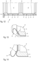
- Fig. 12 shows a further example of an exhaust gas aftertreatment device 54 not according to the invention. Also for Fig. 12
- the same reference numbers are used as in Fig. 1 used.
- the second clamping elements 47 which in turn are designed as latch-like projections and are attached to the wall 49 of the housing 41, are an integral part of the honeycomb support 44 and thus of the canning.
- Fig. 12 the Fig. 3 .
- the first preloading elements 46 acting in the flow direction of the exhaust gas aftertreatment units 42 are in Fig. 12 as in Fig. 1 again designed as separate assemblies, but in contrast to the Fig. 1 a separate first prestressing element 46 is not attached to both axial ends of a respective exhaust gas aftertreatment unit 42, but only to one axial end thereof.
- Fig. 13 shows a detail of the Fig. 6 in the area of two adjacent exhaust aftertreatment units 42.
- the sealing surface 52 between the Fig. 13 shown first prestressing element 46 and an adjacent section of the honeycomb carrier 44 of the adjacent exhaust aftertreatment unit 42 is inclined relative to the radial direction, which runs perpendicular to the flow direction.
- Fig. 14 which is a modification of the detail of the Fig. 13 shows such an inclined position of the sealing surface 52, which, however, in contrast to Fig. 13 is inclined towards the adjacent exhaust aftertreatment unit 42 and not, as in Fig. 13 shown, is tilted away from it.
- Figs. 15 and 16 show further examples of exhaust aftertreatment devices 55 and 56.
- the exhaust aftertreatment units 55 and 56 of the Figs. 15 and 16 basically correspond to the exhaust aftertreatment unit 53 of the Fig. 3 , also in Figs. 15 and 16 Accordingly, the first prestressing elements 46 and the second prestressing elements 47 are designed as integral components of the honeycomb body supports 44 and thus of the respective canning.
- Figs. 15 and 16 differ from that of the Fig. 3 in that the first pre-tensioning elements 46 acting in the flow direction of the respective exhaust gas aftertreatment unit 42 are not designed in the manner of a bellows but rather are formed by a corresponding wall thickness of the honeycomb carrier 44.
- Figs. 15 and 16 differ from each other in that Fig. 16 Adjacent exhaust aftertreatment units 42 do not seal directly against each other in the region of the first prestressing elements 46, but rather against a radially inwardly projecting projection 50 of the receiving housing 41.
- Fig. 17 shows an embodiment of an exhaust gas aftertreatment system 57 according to the invention, which comprises two exhaust gas aftertreatment devices 53 according to Fig. 3
- Each of the two exhaust gas aftertreatment devices 53 has a receiving housing 41 and two exhaust gas aftertreatment units 42 positioned in the receiving housing 41.
- the two exhaust gas aftertreatment devices 53 are connected in series. Exhaust gas, which the exhaust gas aftertreatment system 57 of the Fig. 17 flows through, therefore flows through all exhaust aftertreatment units 42.
- the exhaust aftertreatment system 57 of the Fig. 17 is single-flow.
- a housing 58 is connected between the two exhaust aftertreatment devices 53, which serves, for example, to accommodate sensors such as temperature sensors or pressure sensors. Additionally, the housing 58 can accommodate, for example, a device for introducing a reducing agent into the exhaust gas stream. The housing 58 can also accommodate a soot blower.
- Covers 59 are attached to the opposite ends of the two exhaust gas aftertreatment devices 53, whereby the covers 59 of the exhaust gas aftertreatment system 57 can be connected to exhaust pipes (not shown).
- Figs. 18 and 19 show details of the connection of the receiving housing 41 of one of the Fig. 17 shown exhaust aftertreatment devices 53 with one of the covers 59. With the cover 59 removed (see Fig. 18 ), the corresponding end of the corresponding exhaust gas aftertreatment unit 42 protrudes from the receiving housing 41 with a defined preload stroke VH in the flow direction.
- the prestressing elements 46 of the exhaust gas aftertreatment units 42 arranged in the receiving housing 41 which act in the flow direction, are compressed in order to bring a flange 60 of the cover 59 into contact with a flange 61 of the receiving housing 41 and then to connect the cover 59 and the receiving housing 41 to one another, for example by screwing.
- Fig. 20 shows a cross section through a second exhaust gas aftertreatment system 62, which has only a single exhaust gas aftertreatment device 53, with the covers 59 directly adjoining both sides thereof.
- an intermediate disk 63 is used between the flange 61 of the receiving housing 41 and the flange 60 of the cover 59 to connect the cover 59 to the receiving housing 41 while compressing the first preload elements 46.
- the preload force in the flow direction can be adjusted via the intermediate disk 53.
- Figs. 21, 22 and 23 show details of a third exhaust aftertreatment system 64 with an exhaust aftertreatment device 54 according to Fig. 12 .
- the remaining details are correct Figs. 21, 22 and 23 with the Fig. 20 and with regard to the connection of the cover 59 to the receiving housing 41 with the details of the Figs. 18 and 19 so that the same reference numbers are used for the same assemblies and reference can be made to the above explanations.
- Fig. 17 to 23 also the exhaust aftertreatment devices 40 of the Fig. 1, 2 can be installed in an exhaust aftertreatment system, as well as the exhaust aftertreatment devices 55, 56 of the Figs. 15 and 16 .
- FIG. 17 to 23 details of single-flow exhaust aftertreatment systems 57, 62, 64 show, show Figs. 24, 25 and Figs. 26, 27 and Figs. 28, 29 as well as Fig. 30
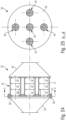
- Figs. 24 and 25 show a multi-flow exhaust aftertreatment system 65, which comprises a total of five parallel-connected exhaust aftertreatment devices 40 according to Fig. 1 includes, but with the difference that Figs. 24 and 25 in the respective housing three exhaust gas aftertreatment units 42 are connected in series and not, as in Fig. 1, 2 only two exhaust aftertreatment units 42.
- FIGs. 24 and 25 A common cover 59 is connected to the respective ends of the five parallel-connected exhaust aftertreatment devices 40.
- a clamping cover 69 is used which is common to all housings 41 of all parallel connected exhaust aftertreatment devices 40 and which also performs the function of the intermediate disc 63 of the Fig. 20 takes over.
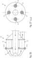
- FIGs. 28 and 29 an exhaust aftertreatment system 67, in which between the left cover 59 and the receiving housings 41 the parallel switched exhaust aftertreatment devices 40, an individual clamping cover 69 is used for each exhaust aftertreatment device 40.
- the inflow side and the outflow side are arranged at opposite ends of the respective exhaust gas aftertreatment system 65, 67.
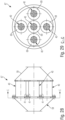
- Figs. 26 and 27 an exhaust aftertreatment system 66, in which the inflow side and outflow side of the exhaust aftertreatment system 26 are formed at the same end or the same side of the exhaust aftertreatment system 66.
- FIGs. 26 and 27 Four exhaust aftertreatment devices 40 are connected in parallel, namely between the covers 59. While in Figs. 24 and 25 one of the covers 59 forms an inlet side and the opposite cover 59 forms an outlet side of the respective exhaust gas aftertreatment system, are in Figs. 26 and 27 Inlet side and outlet side on the right cover 59 of the Fig. 6 At the opposite cover 59, a flow reversal for the exhaust gas takes place. Such a flow reversal for the exhaust gas is already known from the DE 10 2016 205 327 A1 known. In Fig. 26 Arrows illustrate the exhaust gas flow through the exhaust aftertreatment system 66 of the Figs. 26 and 27 .
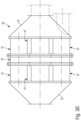
- Fig. 30 shows an exhaust gas aftertreatment system 68 in which two exhaust gas aftertreatment devices 14 are arranged in series one behind the other and several such series circuits are arranged parallel to one another between two covers 59.
- a housing 58 for accommodating a sensor system or for accommodating soot blowers or for accommodating introducing devices for reducing agents can be arranged.
- the flow of the exhaust gas can be either as in Figs. 24, 25 or as in Figs. 26, 27 be executed.
- the series-connected exhaust gas aftertreatment units 42 can be identical or different.
- the two left-hand exhaust aftertreatment units 42 are designed as particulate filters, and the two right-hand exhaust aftertreatment units 42 are designed as SCR catalysts or NOx storage catalysts. It is also possible to leave a position of an exhaust aftertreatment unit 42 free and simply arrange a placeholder there, which cannot perform any exhaust aftertreatment function.
- the prestressing forces for the prestressing elements 46, 47 can be adjusted, in particular, by selecting the material and/or the wall thickness and/or the geometry and/or the number of walls of the prestressing elements 46, 47. As explained above, the prestressing elements 46, 47 can be single-walled or multi-walled.
- the number of bellows or corrugations in the bellows-like prestressing elements 46 can be varied.
- the number of bellows or corrugations in the pawl-like prestressing elements 47 can be varied.
- An exhaust aftertreatment system can be expanded as needed from the above-described components of the housing 41, exhaust aftertreatment units 42, housing 58, and cover 59 in a modular system.
- Housing 41 and exhaust aftertreatment units 42 can be designed with coarse tolerances.
- the preloading elements 26, 27 compensate for such tolerances.
- the preloading elements 26, 27 also provide vibration damping and reduce vibrations in the exhaust system.
Landscapes
- Engineering & Computer Science (AREA)
- Chemical & Material Sciences (AREA)
- Chemical Kinetics & Catalysis (AREA)
- Combustion & Propulsion (AREA)
- Mechanical Engineering (AREA)
- General Engineering & Computer Science (AREA)
- Health & Medical Sciences (AREA)
- Toxicology (AREA)
- Exhaust Gas After Treatment (AREA)
- Processes For Solid Components From Exhaust (AREA)
- Exhaust Gas Treatment By Means Of Catalyst (AREA)
- Catalysts (AREA)
Claims (10)
- Système de post-traitement des gaz d'échappement (57) d'un moteur à combustion interne,comportant un dispositif de post-traitement des gaz d'échappement (53),comportant un boîtier de réception (41),comportant au moins une unité de post-traitement des gaz d'échappement (42) disposée dans le boîtier de réception (41), qui présente un corps en nid d'abeille (43) servant de catalyseur et/ou de filtre à particules et un support de corps en nid d'abeille (44) entourant le corps en nid d'abeille (43) et laissant le corps en nid d'abeille (43) libre au niveau de ses faces d'extrémitéla au moins une unité de post-traitement des gaz d'échappement (42) est renfermée de manière précontrainte dans le boîtier de réception (41) via des premiers éléments de précontrainte (46) agissant dans la direction d'écoulement de l'unité de post-traitement des gaz d'échappement (42) respective et via des deuxièmes éléments de précontrainte (47) agissant perpendiculairement à la direction d'écoulement de l'unité de post-traitement des gaz d'échappement (42) respective,comportant des couvercles (59) pour raccorder le système de post-traitement des gaz d'échappement (57) aux tuyaux d'échappement,comportant plusieurs dispositifs de post-traitement des gaz d'échappement connectés en série (53),caractérisé en ce queentre deux dispositifs de post-traitement des gaz d'échappement (53) un boîtier (58) est connecté, qui sert au moins à renfermer des capteurs, comme par exemple des capteurs de température ou des capteurs de pression.
- Système de post-traitement des gaz d'échappement (57) selon la revendication 1, caractérisé en ce que le boîtier (58) connecté entre deux dispositifs de post-traitement des gaz d'échappement (53) sert en outre à recevoir un dispositif de pour introduire un agent réducteur dans le flux de gaz d'échappement et/ou un souffleur de suie.
- Système de post-traitement des gaz d'échappement (57) selon la revendication 1 ou 2, caractérisé en ce que les premiers éléments de précontrainte (46) agissant dans la direction d'écoulement de l'unité de post-traitement des gaz d'échappement (42) respective et les deuxièmes éléments de précontrainte (47) agissant perpendiculairement à la direction d'écoulement de l'unité de post-traitement des gaz d'échappement (42) respective sont formés par des ensembles de précontrainte séparés (48),chaque ensemble de précontrainte séparé (48) présentant un premier élément de précontrainte (46) agissant dans la direction d'écoulement de l'unité de post-traitement des gaz d'échappement respective (42) et plusieurs deuxièmes éléments de précontrainte (47) agissant perpendiculairement à la direction d'écoulement de l'unité de post-traitement des gaz d'échappement respective (42),les ensembles de précontrainte séparés (48) sur au moins une des extrémités axiales opposées de l'unité de post-traitement des gaz d'échappement (42) respective sont enfichées sur celle-ci, à savoir sur le support de corps en nid d'abeille (44) de l'unité de post-traitement des gaz d'échappement (42) respective.
- Système de post-traitement des gaz d'échappement (57) selon la revendication 3, caractérisé en ce que les ensembles de précontrainte séparés (48) sont à paroi simple ou à parois multiples.
- Système de post-traitement des gaz d'échappement (57) selon la revendication 1, caractérisé en ce que les premiers éléments de précontrainte (46) agissant dans la direction d'écoulement de l'unité de post-traitement des gaz d'échappement (42) respective et/ou les deuxièmes éléments de précontrainte (47) agissant perpendiculairement à la direction d'écoulement de l'unité de post-traitement des gaz d'échappement (42) respective sont conçus comme un composant intégral du support de corps en nid d'abeille (44) de l'unité de post-traitement des gaz d'échappement (42) respective.
- Système de post-traitement des gaz d'échappement (57) selon la revendication 5, caractérisé en ce que le support en nid d'abeille (44) de l'unité de post-traitement des gaz d'échappement (42) respective est à paroi simple ou à parois multiples.
- Système de post-traitement des gaz d'échappement (57) selon une des revendications 1 à 6, caractérisé en ce que les premiers éléments de précontrainte (46) agissant dans la direction d'écoulement de l'unité de post-traitement des gaz d'échappement respective (42) sont conçus comme des éléments de précontrainte de type soufflet.
- Système de post-traitement des gaz d'échappement (57) selon une des revendications 1 à 7, caractérisé en ce que les deuxièmes éléments de précontrainte (47) agissant perpendiculairement à la direction d'écoulement de l'unité de post-traitement des gaz d'échappement (42) respective sont conçus sous forme de protubérances en forme de cliquet.
- Système de post-traitement des gaz d'échappement (57) selon la revendication 8, caractérisé en ce que les protubérances en forme de cliquet sont à paroi simple ou à parois multiples.
- Système de post-traitement des gaz d'échappement (57) selon une des revendications 1 à 9, caractérisé en ce que des surfaces d'étanchéité (52) sur les premiers éléments de précontrainte (46) agissant dans la direction d'écoulement de l'unité de post-traitement des gaz d'échappement respective (42) sont alignées perpendiculairement à la direction d'écoulement de l'unité de post-traitement des gaz d'échappement respective (42).
Applications Claiming Priority (1)
| Application Number | Priority Date | Filing Date | Title |
|---|---|---|---|
| DE102021125550.3A DE102021125550B4 (de) | 2021-10-01 | 2021-10-01 | Abgasnachbehandlungsvorrichtung und Abgasnachbehandlungssystem einer Brennkraftmaschine |
Publications (2)
| Publication Number | Publication Date |
|---|---|
| EP4159986A1 EP4159986A1 (fr) | 2023-04-05 |
| EP4159986B1 true EP4159986B1 (fr) | 2025-06-11 |
Family
ID=83508424
Family Applications (1)
| Application Number | Title | Priority Date | Filing Date |
|---|---|---|---|
| EP22198984.1A Active EP4159986B1 (fr) | 2021-10-01 | 2022-09-30 | Dispositif de post-traitement des gaz d'échappement et système de post-traitement des gaz d'échappement d'un moteur à combustion interne |
Country Status (6)
| Country | Link |
|---|---|
| EP (1) | EP4159986B1 (fr) |
| JP (1) | JP2023053910A (fr) |
| KR (1) | KR20230047903A (fr) |
| CN (1) | CN115929441A (fr) |
| DE (1) | DE102021125550B4 (fr) |
| FI (1) | FI4159986T3 (fr) |
Families Citing this family (1)
| Publication number | Priority date | Publication date | Assignee | Title |
|---|---|---|---|---|
| CN119801702B (zh) * | 2025-01-03 | 2025-07-25 | 亿达天地环保技术股份有限公司 | 一种组合式蜂窝载体结构 |
Family Cites Families (9)
| Publication number | Priority date | Publication date | Assignee | Title |
|---|---|---|---|---|
| DE2236592A1 (de) | 1972-07-26 | 1974-02-07 | Kali Chemie Ag | Gehaeuse mit federnder einspannvorrichtung fuer keramische monolithische katalysatorkoerper |
| DE2364425A1 (de) | 1973-12-22 | 1975-07-10 | Boysen Friedrich Kg | Katalysator, insbesondere fuer auspuffund entgiftungsanlagen |
| DE3406721A1 (de) * | 1984-02-24 | 1985-09-12 | LEISTRITZ Maschinenfabrik GmbH, 8500 Nürnberg | Katalytische abgasentgiftungseinrichtung |
| DE3512580A1 (de) * | 1985-04-06 | 1986-10-16 | Üründül, Celâl, 6800 Mannheim | Fixierung eines katalysatorkoerpers in einer patronenhuelse zur elastischen halterung des katalysatorkoerpers in einem gehaeuse |
| US20050002836A1 (en) * | 2001-04-13 | 2005-01-06 | Hardesty Jeffrey B. | Gas treatment device, and methods of making and using the same |
| EP1797295A1 (fr) * | 2004-09-08 | 2007-06-20 | Donaldson Company, Inc. | Joint pour une composante de systeme d'echappement des moteurs |
| DE102015218503B4 (de) | 2015-09-25 | 2025-09-04 | Purem GmbH | Abgasnachbehandlungseinrichtung und Kartusche |
| DE102016205327A1 (de) | 2016-03-31 | 2017-10-05 | Man Diesel & Turbo Se | Abgasnachbehandlungssystem und Brennkraftmaschine |
| GB201704520D0 (en) * | 2017-03-22 | 2017-05-03 | Teconnex Ltd | Clamping apparatus and method of use thereof |
-
2021
- 2021-10-01 DE DE102021125550.3A patent/DE102021125550B4/de active Active
-
2022
- 2022-09-22 JP JP2022151807A patent/JP2023053910A/ja active Pending
- 2022-09-28 KR KR1020220123260A patent/KR20230047903A/ko active Pending
- 2022-09-30 EP EP22198984.1A patent/EP4159986B1/fr active Active
- 2022-09-30 FI FIEP22198984.1T patent/FI4159986T3/fi active
- 2022-09-30 CN CN202211205637.5A patent/CN115929441A/zh active Pending
Also Published As
| Publication number | Publication date |
|---|---|
| CN115929441A (zh) | 2023-04-07 |
| DE102021125550B4 (de) | 2024-05-16 |
| EP4159986A1 (fr) | 2023-04-05 |
| KR20230047903A (ko) | 2023-04-10 |
| JP2023053910A (ja) | 2023-04-13 |
| DE102021125550A1 (de) | 2023-04-06 |
| FI4159986T3 (fi) | 2025-09-11 |
Similar Documents
| Publication | Publication Date | Title |
|---|---|---|
| EP3231498B1 (fr) | Système de filtre | |
| DE112012000930B4 (de) | Abgasreinigungsvorrichtung | |
| EP2654922B1 (fr) | Élément de filtre à air | |
| EP3463616A1 (fr) | Élément filtrant d'un dispositif de filtration, boîtier de filtre et dispositif de filtration | |
| EP4048426B1 (fr) | Dispositif de traitement pour traiter des fluides, en particulier des fluides liquides, et tête de raccordement pour un dispositif de traitement | |
| DE112016004899T5 (de) | Filter mit axialer Dichtung mit variablem Querschnitt | |
| EP4159986B1 (fr) | Dispositif de post-traitement des gaz d'échappement et système de post-traitement des gaz d'échappement d'un moteur à combustion interne | |
| DE102017005356A1 (de) | Abgasnachbehandlungsvorrichtung einer Brennkraftmaschine eines Kraftfahrzeugs | |
| EP4048424A1 (fr) | Dispositif de traitement pour traiter des fluides, en particulier des fluides liquides, et unité de traitement et tête de raccordement pour un dispositif de traitement | |
| EP2461887B1 (fr) | Dispositif de filtration et utilisation d'un élément filtre enroulé | |
| EP2616649B1 (fr) | Unité de traitement de gaz d'échappement, en particulier pour une conduite de recyclage de gaz d'échappement | |
| DE69708754T2 (de) | Brennkraftmaschine mit einer Reinigungsvorrichtung für die Durchblasgase des Kurbelgehäuses | |
| WO2025108671A1 (fr) | Élément filtrant, en particulier pour filtration de gaz | |
| EP2194251B1 (fr) | Fixation autoporteuse pour corps de support de catalyseur | |
| WO2015075061A1 (fr) | Cartouche filtrante destinée à un dispositif filtrant | |
| DE10296178B4 (de) | Flexibles Leitungselement | |
| DE20313032U1 (de) | Sintermetallpartikelfilter | |
| EP1686303B1 (fr) | Raccord démontable pour éléments profilés avec anneau de centrage | |
| EP4053384B1 (fr) | Dispositif de traitement ultérieur des gaz d'échappement pourvu de substrats multiples de purification des gaz d'échappement | |
| DE102022204100A1 (de) | Abgaskühler für eine Abgasrückführeinrichtung | |
| DE102005055074A1 (de) | Filtereinrichtung, insbesondere für ein Abgassystem einer Brennkraftmaschine | |
| DE102023107299A1 (de) | Filtervorrichtung für gasförmige Medien, Filterelement, Verwendung eines Filterelementes, Verfahren zum Zusammenbau einer Filtervorrichtung | |
| DE102023107300A1 (de) | Filterelement für gasförmige Medien, Filtervorrichtung, Verwendung eines Filterelementes und Verfahren zum Zusammenbau einer Filtervorrichtung | |
| DE102023107293A1 (de) | Filtervorrichtung für gasförmiges Medium, Filterelement, Verwendung eines Filterelements und Verfahren zum Zusammenbau einer Filtervorrichtung | |
| DE102022119709A1 (de) | Sekundärelement und filtersystem |
Legal Events
| Date | Code | Title | Description |
|---|---|---|---|
| PUAI | Public reference made under article 153(3) epc to a published international application that has entered the european phase |
Free format text: ORIGINAL CODE: 0009012 |
|
| STAA | Information on the status of an ep patent application or granted ep patent |
Free format text: STATUS: THE APPLICATION HAS BEEN PUBLISHED |
|
| STAA | Information on the status of an ep patent application or granted ep patent |
Free format text: STATUS: REQUEST FOR EXAMINATION WAS MADE |
|
| AK | Designated contracting states |
Kind code of ref document: A1 Designated state(s): AL AT BE BG CH CY CZ DE DK EE ES FI FR GB GR HR HU IE IS IT LI LT LU LV MC MK MT NL NO PL PT RO RS SE SI SK SM TR |
|
| 17P | Request for examination filed |
Effective date: 20230323 |
|
| RBV | Designated contracting states (corrected) |
Designated state(s): AL AT BE BG CH CY CZ DE DK EE ES FI FR GB GR HR HU IE IS IT LI LT LU LV MC MK MT NL NO PL PT RO RS SE SI SK SM TR |
|
| STAA | Information on the status of an ep patent application or granted ep patent |
Free format text: STATUS: EXAMINATION IS IN PROGRESS |
|
| 17Q | First examination report despatched |
Effective date: 20240419 |
|
| GRAP | Despatch of communication of intention to grant a patent |
Free format text: ORIGINAL CODE: EPIDOSNIGR1 |
|
| STAA | Information on the status of an ep patent application or granted ep patent |
Free format text: STATUS: GRANT OF PATENT IS INTENDED |
|
| INTG | Intention to grant announced |
Effective date: 20250204 |
|
| GRAS | Grant fee paid |
Free format text: ORIGINAL CODE: EPIDOSNIGR3 |
|
| GRAA | (expected) grant |
Free format text: ORIGINAL CODE: 0009210 |
|
| STAA | Information on the status of an ep patent application or granted ep patent |
Free format text: STATUS: THE PATENT HAS BEEN GRANTED |
|
| AK | Designated contracting states |
Kind code of ref document: B1 Designated state(s): AL AT BE BG CH CY CZ DE DK EE ES FI FR GB GR HR HU IE IS IT LI LT LU LV MC MK MT NL NO PL PT RO RS SE SI SK SM TR |
|
| REG | Reference to a national code |
Ref country code: GB Ref legal event code: FG4D Free format text: NOT ENGLISH |
|
| REG | Reference to a national code |
Ref country code: CH Ref legal event code: EP |
|
| REG | Reference to a national code |
Ref country code: IE Ref legal event code: FG4D Free format text: LANGUAGE OF EP DOCUMENT: GERMAN |
|
| REG | Reference to a national code |
Ref country code: DE Ref legal event code: R096 Ref document number: 502022004226 Country of ref document: DE |
|
| RAP4 | Party data changed (patent owner data changed or rights of a patent transferred) |
Owner name: EVERLLENCE SE |
|
| REG | Reference to a national code |
Ref country code: NL Ref legal event code: FP |
|
| REG | Reference to a national code |
Ref country code: FI Ref legal event code: FGE |
|
| REG | Reference to a national code |
Ref country code: SE Ref legal event code: TRGR |
|
| REG | Reference to a national code |
Ref country code: CH Ref legal event code: U11 Free format text: ST27 STATUS EVENT CODE: U-0-0-U10-U11 (AS PROVIDED BY THE NATIONAL OFFICE) Effective date: 20251001 |
|
| PG25 | Lapsed in a contracting state [announced via postgrant information from national office to epo] |
Ref country code: ES Free format text: LAPSE BECAUSE OF FAILURE TO SUBMIT A TRANSLATION OF THE DESCRIPTION OR TO PAY THE FEE WITHIN THE PRESCRIBED TIME-LIMIT Effective date: 20250611 |
|
| PGFP | Annual fee paid to national office [announced via postgrant information from national office to epo] |
Ref country code: FI Payment date: 20250926 Year of fee payment: 4 |
|
| REG | Reference to a national code |
Ref country code: LT Ref legal event code: MG9D |
|
| PG25 | Lapsed in a contracting state [announced via postgrant information from national office to epo] |
Ref country code: GR Free format text: LAPSE BECAUSE OF FAILURE TO SUBMIT A TRANSLATION OF THE DESCRIPTION OR TO PAY THE FEE WITHIN THE PRESCRIBED TIME-LIMIT Effective date: 20250912 |
|
| PGFP | Annual fee paid to national office [announced via postgrant information from national office to epo] |
Ref country code: NO Payment date: 20250923 Year of fee payment: 4 |
|
| PGFP | Annual fee paid to national office [announced via postgrant information from national office to epo] |
Ref country code: NL Payment date: 20250918 Year of fee payment: 4 |
|
| PG25 | Lapsed in a contracting state [announced via postgrant information from national office to epo] |
Ref country code: BG Free format text: LAPSE BECAUSE OF FAILURE TO SUBMIT A TRANSLATION OF THE DESCRIPTION OR TO PAY THE FEE WITHIN THE PRESCRIBED TIME-LIMIT Effective date: 20250611 |
|
| PG25 | Lapsed in a contracting state [announced via postgrant information from national office to epo] |
Ref country code: HR Free format text: LAPSE BECAUSE OF FAILURE TO SUBMIT A TRANSLATION OF THE DESCRIPTION OR TO PAY THE FEE WITHIN THE PRESCRIBED TIME-LIMIT Effective date: 20250611 |
|
| PGFP | Annual fee paid to national office [announced via postgrant information from national office to epo] |
Ref country code: FR Payment date: 20250922 Year of fee payment: 4 |
|
| PGFP | Annual fee paid to national office [announced via postgrant information from national office to epo] |
Ref country code: SE Payment date: 20250918 Year of fee payment: 4 |
|
| PG25 | Lapsed in a contracting state [announced via postgrant information from national office to epo] |
Ref country code: RS Free format text: LAPSE BECAUSE OF FAILURE TO SUBMIT A TRANSLATION OF THE DESCRIPTION OR TO PAY THE FEE WITHIN THE PRESCRIBED TIME-LIMIT Effective date: 20250911 |
|
| PG25 | Lapsed in a contracting state [announced via postgrant information from national office to epo] |
Ref country code: LV Free format text: LAPSE BECAUSE OF FAILURE TO SUBMIT A TRANSLATION OF THE DESCRIPTION OR TO PAY THE FEE WITHIN THE PRESCRIBED TIME-LIMIT Effective date: 20250611 |
|
| PG25 | Lapsed in a contracting state [announced via postgrant information from national office to epo] |
Ref country code: PT Free format text: LAPSE BECAUSE OF FAILURE TO SUBMIT A TRANSLATION OF THE DESCRIPTION OR TO PAY THE FEE WITHIN THE PRESCRIBED TIME-LIMIT Effective date: 20251013 |