EP4159986B1 - Abgasnachbehandlungsvorrichtung und abgasnachbehandlungssystem einer brennkraftmaschine - Google Patents
Abgasnachbehandlungsvorrichtung und abgasnachbehandlungssystem einer brennkraftmaschine Download PDFInfo
- Publication number
- EP4159986B1 EP4159986B1 EP22198984.1A EP22198984A EP4159986B1 EP 4159986 B1 EP4159986 B1 EP 4159986B1 EP 22198984 A EP22198984 A EP 22198984A EP 4159986 B1 EP4159986 B1 EP 4159986B1
- Authority
- EP
- European Patent Office
- Prior art keywords
- exhaust gas
- flow direction
- treatment unit
- preload
- treatment
- Prior art date
- Legal status (The legal status is an assumption and is not a legal conclusion. Google has not performed a legal analysis and makes no representation as to the accuracy of the status listed.)
- Active
Links
Images


Classifications
-
- F—MECHANICAL ENGINEERING; LIGHTING; HEATING; WEAPONS; BLASTING
- F01—MACHINES OR ENGINES IN GENERAL; ENGINE PLANTS IN GENERAL; STEAM ENGINES
- F01N—GAS-FLOW SILENCERS OR EXHAUST APPARATUS FOR MACHINES OR ENGINES IN GENERAL; GAS-FLOW SILENCERS OR EXHAUST APPARATUS FOR INTERNAL-COMBUSTION ENGINES
- F01N3/00—Exhaust or silencing apparatus having means for purifying, rendering innocuous, or otherwise treating exhaust
- F01N3/08—Exhaust or silencing apparatus having means for purifying, rendering innocuous, or otherwise treating exhaust for rendering innocuous
- F01N3/10—Exhaust or silencing apparatus having means for purifying, rendering innocuous, or otherwise treating exhaust for rendering innocuous by thermal or catalytic conversion of noxious components of exhaust
- F01N3/24—Exhaust or silencing apparatus having means for purifying, rendering innocuous, or otherwise treating exhaust for rendering innocuous by thermal or catalytic conversion of noxious components of exhaust characterised by constructional aspects of converting apparatus
- F01N3/28—Construction of catalytic reactors
- F01N3/2839—Arrangements for mounting catalyst support in housing, e.g. with means for compensating thermal expansion or vibration
- F01N3/2842—Arrangements for mounting catalyst support in housing, e.g. with means for compensating thermal expansion or vibration specially adapted for monolithic supports, e.g. of honeycomb type
-
- F—MECHANICAL ENGINEERING; LIGHTING; HEATING; WEAPONS; BLASTING
- F01—MACHINES OR ENGINES IN GENERAL; ENGINE PLANTS IN GENERAL; STEAM ENGINES
- F01N—GAS-FLOW SILENCERS OR EXHAUST APPARATUS FOR MACHINES OR ENGINES IN GENERAL; GAS-FLOW SILENCERS OR EXHAUST APPARATUS FOR INTERNAL-COMBUSTION ENGINES
- F01N13/00—Exhaust or silencing apparatus characterised by constructional features
- F01N13/18—Construction facilitating manufacture, assembly, or disassembly
- F01N13/1805—Fixing exhaust manifolds, exhaust pipes or pipe sections to each other, to engine or to vehicle body
- F01N13/1811—Fixing exhaust manifolds, exhaust pipes or pipe sections to each other, to engine or to vehicle body with means permitting relative movement, e.g. compensation of thermal expansion or vibration
- F01N13/1816—Fixing exhaust manifolds, exhaust pipes or pipe sections to each other, to engine or to vehicle body with means permitting relative movement, e.g. compensation of thermal expansion or vibration the pipe sections being joined together by flexible tubular elements only, e.g. using bellows or strip-wound pipes
-
- F—MECHANICAL ENGINEERING; LIGHTING; HEATING; WEAPONS; BLASTING
- F01—MACHINES OR ENGINES IN GENERAL; ENGINE PLANTS IN GENERAL; STEAM ENGINES
- F01N—GAS-FLOW SILENCERS OR EXHAUST APPARATUS FOR MACHINES OR ENGINES IN GENERAL; GAS-FLOW SILENCERS OR EXHAUST APPARATUS FOR INTERNAL-COMBUSTION ENGINES
- F01N3/00—Exhaust or silencing apparatus having means for purifying, rendering innocuous, or otherwise treating exhaust
- F01N3/02—Exhaust or silencing apparatus having means for purifying, rendering innocuous, or otherwise treating exhaust for cooling, or for removing solid constituents of, exhaust
- F01N3/021—Exhaust or silencing apparatus having means for purifying, rendering innocuous, or otherwise treating exhaust for cooling, or for removing solid constituents of, exhaust by means of filters
-
- F—MECHANICAL ENGINEERING; LIGHTING; HEATING; WEAPONS; BLASTING
- F01—MACHINES OR ENGINES IN GENERAL; ENGINE PLANTS IN GENERAL; STEAM ENGINES
- F01N—GAS-FLOW SILENCERS OR EXHAUST APPARATUS FOR MACHINES OR ENGINES IN GENERAL; GAS-FLOW SILENCERS OR EXHAUST APPARATUS FOR INTERNAL-COMBUSTION ENGINES
- F01N3/00—Exhaust or silencing apparatus having means for purifying, rendering innocuous, or otherwise treating exhaust
- F01N3/08—Exhaust or silencing apparatus having means for purifying, rendering innocuous, or otherwise treating exhaust for rendering innocuous
- F01N3/10—Exhaust or silencing apparatus having means for purifying, rendering innocuous, or otherwise treating exhaust for rendering innocuous by thermal or catalytic conversion of noxious components of exhaust
- F01N3/24—Exhaust or silencing apparatus having means for purifying, rendering innocuous, or otherwise treating exhaust for rendering innocuous by thermal or catalytic conversion of noxious components of exhaust characterised by constructional aspects of converting apparatus
- F01N3/28—Construction of catalytic reactors
- F01N3/2839—Arrangements for mounting catalyst support in housing, e.g. with means for compensating thermal expansion or vibration
- F01N3/2853—Arrangements for mounting catalyst support in housing, e.g. with means for compensating thermal expansion or vibration using mats or gaskets between catalyst body and housing
- F01N3/2867—Arrangements for mounting catalyst support in housing, e.g. with means for compensating thermal expansion or vibration using mats or gaskets between catalyst body and housing the mats or gaskets being placed at the front or end face of catalyst body
-
- F—MECHANICAL ENGINEERING; LIGHTING; HEATING; WEAPONS; BLASTING
- F01—MACHINES OR ENGINES IN GENERAL; ENGINE PLANTS IN GENERAL; STEAM ENGINES
- F01N—GAS-FLOW SILENCERS OR EXHAUST APPARATUS FOR MACHINES OR ENGINES IN GENERAL; GAS-FLOW SILENCERS OR EXHAUST APPARATUS FOR INTERNAL-COMBUSTION ENGINES
- F01N3/00—Exhaust or silencing apparatus having means for purifying, rendering innocuous, or otherwise treating exhaust
- F01N3/08—Exhaust or silencing apparatus having means for purifying, rendering innocuous, or otherwise treating exhaust for rendering innocuous
- F01N3/10—Exhaust or silencing apparatus having means for purifying, rendering innocuous, or otherwise treating exhaust for rendering innocuous by thermal or catalytic conversion of noxious components of exhaust
- F01N3/24—Exhaust or silencing apparatus having means for purifying, rendering innocuous, or otherwise treating exhaust for rendering innocuous by thermal or catalytic conversion of noxious components of exhaust characterised by constructional aspects of converting apparatus
- F01N3/28—Construction of catalytic reactors
- F01N3/2839—Arrangements for mounting catalyst support in housing, e.g. with means for compensating thermal expansion or vibration
- F01N3/2875—Arrangements for mounting catalyst support in housing, e.g. with means for compensating thermal expansion or vibration by using elastic means, e.g. spring leaves, for retaining catalyst body in the housing
-
- F—MECHANICAL ENGINEERING; LIGHTING; HEATING; WEAPONS; BLASTING
- F01—MACHINES OR ENGINES IN GENERAL; ENGINE PLANTS IN GENERAL; STEAM ENGINES
- F01N—GAS-FLOW SILENCERS OR EXHAUST APPARATUS FOR MACHINES OR ENGINES IN GENERAL; GAS-FLOW SILENCERS OR EXHAUST APPARATUS FOR INTERNAL-COMBUSTION ENGINES
- F01N13/00—Exhaust or silencing apparatus characterised by constructional features
- F01N13/18—Construction facilitating manufacture, assembly, or disassembly
- F01N13/1872—Construction facilitating manufacture, assembly, or disassembly the assembly using stamp-formed parts or otherwise deformed sheet-metal
-
- F—MECHANICAL ENGINEERING; LIGHTING; HEATING; WEAPONS; BLASTING
- F01—MACHINES OR ENGINES IN GENERAL; ENGINE PLANTS IN GENERAL; STEAM ENGINES
- F01N—GAS-FLOW SILENCERS OR EXHAUST APPARATUS FOR MACHINES OR ENGINES IN GENERAL; GAS-FLOW SILENCERS OR EXHAUST APPARATUS FOR INTERNAL-COMBUSTION ENGINES
- F01N2330/00—Structure of catalyst support or particle filter
- F01N2330/06—Ceramic, e.g. monoliths
-
- F—MECHANICAL ENGINEERING; LIGHTING; HEATING; WEAPONS; BLASTING
- F01—MACHINES OR ENGINES IN GENERAL; ENGINE PLANTS IN GENERAL; STEAM ENGINES
- F01N—GAS-FLOW SILENCERS OR EXHAUST APPARATUS FOR MACHINES OR ENGINES IN GENERAL; GAS-FLOW SILENCERS OR EXHAUST APPARATUS FOR INTERNAL-COMBUSTION ENGINES
- F01N2350/00—Arrangements for fitting catalyst support or particle filter element in the housing
- F01N2350/02—Fitting ceramic monoliths in a metallic housing
- F01N2350/04—Fitting ceramic monoliths in a metallic housing with means compensating thermal expansion
-
- F—MECHANICAL ENGINEERING; LIGHTING; HEATING; WEAPONS; BLASTING
- F01—MACHINES OR ENGINES IN GENERAL; ENGINE PLANTS IN GENERAL; STEAM ENGINES
- F01N—GAS-FLOW SILENCERS OR EXHAUST APPARATUS FOR MACHINES OR ENGINES IN GENERAL; GAS-FLOW SILENCERS OR EXHAUST APPARATUS FOR INTERNAL-COMBUSTION ENGINES
- F01N2450/00—Methods or apparatus for fitting, inserting or repairing different elements
- F01N2450/18—Methods or apparatus for fitting, inserting or repairing different elements by using quick-active type locking mechanisms, e.g. clips
-
- F—MECHANICAL ENGINEERING; LIGHTING; HEATING; WEAPONS; BLASTING
- F01—MACHINES OR ENGINES IN GENERAL; ENGINE PLANTS IN GENERAL; STEAM ENGINES
- F01N—GAS-FLOW SILENCERS OR EXHAUST APPARATUS FOR MACHINES OR ENGINES IN GENERAL; GAS-FLOW SILENCERS OR EXHAUST APPARATUS FOR INTERNAL-COMBUSTION ENGINES
- F01N2450/00—Methods or apparatus for fitting, inserting or repairing different elements
- F01N2450/30—Removable or rechangeable blocks or cartridges, e.g. for filters
-
- F—MECHANICAL ENGINEERING; LIGHTING; HEATING; WEAPONS; BLASTING
- F01—MACHINES OR ENGINES IN GENERAL; ENGINE PLANTS IN GENERAL; STEAM ENGINES
- F01N—GAS-FLOW SILENCERS OR EXHAUST APPARATUS FOR MACHINES OR ENGINES IN GENERAL; GAS-FLOW SILENCERS OR EXHAUST APPARATUS FOR INTERNAL-COMBUSTION ENGINES
- F01N2470/00—Structure or shape of exhaust gas passages, pipes or tubes
- F01N2470/12—Tubes being corrugated
-
- F—MECHANICAL ENGINEERING; LIGHTING; HEATING; WEAPONS; BLASTING
- F01—MACHINES OR ENGINES IN GENERAL; ENGINE PLANTS IN GENERAL; STEAM ENGINES
- F01N—GAS-FLOW SILENCERS OR EXHAUST APPARATUS FOR MACHINES OR ENGINES IN GENERAL; GAS-FLOW SILENCERS OR EXHAUST APPARATUS FOR INTERNAL-COMBUSTION ENGINES
- F01N2590/00—Exhaust or silencing apparatus adapted to particular use, e.g. for military applications, airplanes, submarines
- F01N2590/02—Exhaust or silencing apparatus adapted to particular use, e.g. for military applications, airplanes, submarines for marine vessels or naval applications
-
- F—MECHANICAL ENGINEERING; LIGHTING; HEATING; WEAPONS; BLASTING
- F01—MACHINES OR ENGINES IN GENERAL; ENGINE PLANTS IN GENERAL; STEAM ENGINES
- F01N—GAS-FLOW SILENCERS OR EXHAUST APPARATUS FOR MACHINES OR ENGINES IN GENERAL; GAS-FLOW SILENCERS OR EXHAUST APPARATUS FOR INTERNAL-COMBUSTION ENGINES
- F01N2590/00—Exhaust or silencing apparatus adapted to particular use, e.g. for military applications, airplanes, submarines
- F01N2590/08—Exhaust or silencing apparatus adapted to particular use, e.g. for military applications, airplanes, submarines for heavy duty applications, e.g. trucks, buses, tractors, locomotives
-
- F—MECHANICAL ENGINEERING; LIGHTING; HEATING; WEAPONS; BLASTING
- F01—MACHINES OR ENGINES IN GENERAL; ENGINE PLANTS IN GENERAL; STEAM ENGINES
- F01N—GAS-FLOW SILENCERS OR EXHAUST APPARATUS FOR MACHINES OR ENGINES IN GENERAL; GAS-FLOW SILENCERS OR EXHAUST APPARATUS FOR INTERNAL-COMBUSTION ENGINES
- F01N2590/00—Exhaust or silencing apparatus adapted to particular use, e.g. for military applications, airplanes, submarines
- F01N2590/10—Exhaust or silencing apparatus adapted to particular use, e.g. for military applications, airplanes, submarines for stationary applications
-
- F—MECHANICAL ENGINEERING; LIGHTING; HEATING; WEAPONS; BLASTING
- F01—MACHINES OR ENGINES IN GENERAL; ENGINE PLANTS IN GENERAL; STEAM ENGINES
- F01N—GAS-FLOW SILENCERS OR EXHAUST APPARATUS FOR MACHINES OR ENGINES IN GENERAL; GAS-FLOW SILENCERS OR EXHAUST APPARATUS FOR INTERNAL-COMBUSTION ENGINES
- F01N3/00—Exhaust or silencing apparatus having means for purifying, rendering innocuous, or otherwise treating exhaust
- F01N3/02—Exhaust or silencing apparatus having means for purifying, rendering innocuous, or otherwise treating exhaust for cooling, or for removing solid constituents of, exhaust
- F01N3/021—Exhaust or silencing apparatus having means for purifying, rendering innocuous, or otherwise treating exhaust for cooling, or for removing solid constituents of, exhaust by means of filters
- F01N3/0211—Arrangements for mounting filtering elements in housing, e.g. with means for compensating thermal expansion or vibration
-
- F—MECHANICAL ENGINEERING; LIGHTING; HEATING; WEAPONS; BLASTING
- F01—MACHINES OR ENGINES IN GENERAL; ENGINE PLANTS IN GENERAL; STEAM ENGINES
- F01N—GAS-FLOW SILENCERS OR EXHAUST APPARATUS FOR MACHINES OR ENGINES IN GENERAL; GAS-FLOW SILENCERS OR EXHAUST APPARATUS FOR INTERNAL-COMBUSTION ENGINES
- F01N3/00—Exhaust or silencing apparatus having means for purifying, rendering innocuous, or otherwise treating exhaust
- F01N3/08—Exhaust or silencing apparatus having means for purifying, rendering innocuous, or otherwise treating exhaust for rendering innocuous
- F01N3/10—Exhaust or silencing apparatus having means for purifying, rendering innocuous, or otherwise treating exhaust for rendering innocuous by thermal or catalytic conversion of noxious components of exhaust
- F01N3/24—Exhaust or silencing apparatus having means for purifying, rendering innocuous, or otherwise treating exhaust for rendering innocuous by thermal or catalytic conversion of noxious components of exhaust characterised by constructional aspects of converting apparatus
- F01N3/28—Construction of catalytic reactors
- F01N3/2839—Arrangements for mounting catalyst support in housing, e.g. with means for compensating thermal expansion or vibration
- F01N3/2853—Arrangements for mounting catalyst support in housing, e.g. with means for compensating thermal expansion or vibration using mats or gaskets between catalyst body and housing
-
- Y—GENERAL TAGGING OF NEW TECHNOLOGICAL DEVELOPMENTS; GENERAL TAGGING OF CROSS-SECTIONAL TECHNOLOGIES SPANNING OVER SEVERAL SECTIONS OF THE IPC; TECHNICAL SUBJECTS COVERED BY FORMER USPC CROSS-REFERENCE ART COLLECTIONS [XRACs] AND DIGESTS
- Y02—TECHNOLOGIES OR APPLICATIONS FOR MITIGATION OR ADAPTATION AGAINST CLIMATE CHANGE
- Y02T—CLIMATE CHANGE MITIGATION TECHNOLOGIES RELATED TO TRANSPORTATION
- Y02T10/00—Road transport of goods or passengers
- Y02T10/10—Internal combustion engine [ICE] based vehicles
- Y02T10/12—Improving ICE efficiencies
Definitions
- the invention relates to an exhaust gas aftertreatment system of an internal combustion engine according to the preamble of claim 1.
- the present invention relates to the field of so-called large internal combustion engines, whose cylinders have piston diameters of at least 140 mm, in particular of at least 175 mm.
- large internal combustion engines include, for example, marine engines.
- Such large internal combustion engines can be designed as diesel engines, gas engines, or dual-fuel engines. In dual-fuel engines, a liquid fuel, in particular a diesel fuel, can be burned in a first operating state, and a gaseous fuel, in particular natural gas, can be burned in a second operating state.
- Exhaust gas aftertreatment is also playing an increasingly important role in the field of large combustion engines.
- the exhaust gas aftertreatment system disclosed therein has a reactor chamber, with an SCR catalyst arranged in the reactor chamber. It is known that such an SCR catalyst has several exhaust gas aftertreatment units connected in parallel, through which exhaust gas flows, wherein each exhaust gas aftertreatment unit has a honeycomb body that is held by a honeycomb body carrier and is arranged in a receiving housing via the honeycomb body carrier.
- the honeycomb body carrier is also referred to as a canning, which surrounds the respective honeycomb body on the outside, leaving its end faces free.
- EP 3 147 472 A1 discloses an exhaust aftertreatment system of an internal combustion engine according to the preamble of claim 1.
- the invention is based on the object of creating a novel exhaust gas aftertreatment system for an internal combustion engine.
- the preloading elements acting in the flow direction and perpendicular to the flow direction of the respective exhaust aftertreatment unit ensure that the exhaust gas is guided through the at least one honeycomb body of the at least one exhaust aftertreatment unit and does not flow past the honeycomb body via gaps between the honeycomb body support of the respective honeycomb body and the receiving housing. This can be achieved with minimal effort using the first preloading elements acting in the flow direction of the respective exhaust aftertreatment unit and the second preloading elements acting perpendicular to the flow direction of the respective exhaust aftertreatment unit.
- the first prestressing elements acting in the flow direction of the respective exhaust gas aftertreatment unit and the second prestressing elements acting perpendicular to the flow direction of the respective exhaust gas aftertreatment unit are formed by separate prestressing assemblies, wherein each separate prestressing assembly has a first prestressing element acting in the flow direction of the respective exhaust gas aftertreatment unit and a plurality of second prestressing elements acting perpendicular to the flow direction of the respective exhaust gas aftertreatment unit, and wherein the separate prestressing assemblies are plugged onto the respective exhaust gas aftertreatment unit at at least one of opposite axial ends of the same, namely onto the honeycomb body carrier of the respective exhaust gas aftertreatment unit.
- the prestressing elements are formed by separate prestressing assemblies that are plugged onto the respective exhaust gas aftertreatment unit, the prestressing assemblies can be reused, in particular if an exhaust gas aftertreatment unit has to be replaced, for example as a result of a blocked honeycomb body.
- the first prestressing elements acting in the flow direction of the respective exhaust gas aftertreatment unit are designed as bellows-like prestressing elements.
- the prestressing of the respective exhaust gas aftertreatment unit in the flow direction of the respective exhaust gas aftertreatment unit can be provided simply and advantageously via bellows-like prestressing elements.
- the second prestressing elements acting perpendicular to the flow direction of the respective exhaust gas aftertreatment unit are designed as latch-like projections.
- the prestressing of the respective exhaust gas aftertreatment unit perpendicular to the flow direction of the respective exhaust gas aftertreatment unit can be provided simply and reliably via latch-like projections.
- the pawl-like projections form an angle of 90° with the flow direction.
- the respective exhaust gas aftertreatment unit can be arranged particularly advantageously in the receiving housing together with the preloading elements.
- sealing surfaces on the first preloading elements acting in the flow direction of the respective exhaust aftertreatment unit are aligned perpendicular to the flow direction of the respective exhaust aftertreatment unit. This is particularly advantageous when multiple exhaust aftertreatment units are arranged one behind the other in a series connection in a receiving housing. In this case, a manufacturing tolerance in the area of the exhaust aftertreatment unit ensures that the sealing effect on the sealing surfaces is not impaired.
- the invention relates to an exhaust aftertreatment system for an internal combustion engine, in particular a large internal combustion engine.
- a large internal combustion engine is, in particular, a marine engine, which can be configured as a diesel engine, a gas engine, or a dual-fuel engine.
- a large internal combustion engine has cylinders with a piston diameter of at least 140 mm, in particular of at least 175 mm.
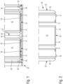
- Fig. 1 shows details of an exhaust gas aftertreatment device 40 not according to the invention.
- the exhaust gas aftertreatment device 40 has a receiving housing 41 and, in the example shown, a plurality of exhaust gas aftertreatment units 42 arranged in the receiving housing 41.
- a plurality of exhaust gas aftertreatment units 42 arranged in the receiving housing 41.
- two exhaust aftertreatment units 42 connected in series are shown, both of which are arranged in the receiving housing 41.
- the receiving housing 41 is in Fig. 1, 2 tubular in design.
- a flow direction through the receiving housing 41 or the exhaust aftertreatment units 42 arranged in the receiving housing 41 extends in the axial direction thereof. If the tubular receiving housing 41 and the exhaust aftertreatment units 42 arranged in the receiving housing 41 are circular in cross-section, the radial direction of the receiving housing 41 or the exhaust aftertreatment units 42 arranged in the receiving housing 41 extends perpendicular to the flow direction thereof.
- the cross sections of the receiving housing 41 and the exhaust aftertreatment units 42 can also be rectangular, square, oval, or the like.
- Each exhaust gas aftertreatment unit 42 has a honeycomb body 43 serving as a catalyst and/or particulate filter, as well as a honeycomb body support 44 surrounding the honeycomb body 43 on the outside and leaving the honeycomb body 43 free at the end faces thereof.
- the honeycomb body support 44 is also referred to as a canning.
- a fiber mat 45 is arranged between the honeycomb body 43 and the honeycomb support 44 of the exhaust aftertreatment units 42 shown there. The fiber mat 45 also leaves the end faces of the respective honeycomb body 43, which define an inlet side and an outlet side for the exhaust gas, exposed.
- the respective exhaust gas aftertreatment unit 43 is pre-tensioned in the receiving housing 41 via pre-tensioning elements.
- the respective exhaust gas aftertreatment unit 42 is positioned in the receiving housing 41 in a prestressed manner both via first prestressing elements 46 acting in the flow direction of the exhaust gas aftertreatment unit 42 and via second prestressing elements 47 acting perpendicular to the flow direction of the respective exhaust gas aftertreatment unit 42.
- the prestressing elements 46, 47 effect a spring-elastic prestress of the respective exhaust gas aftertreatment unit. 42 in the receiving housing 41 in the flow direction and perpendicular to the flow direction.
- the first prestressing elements 46 acting in the flow direction or in the axial direction of the respective exhaust gas aftertreatment unit 42 and the second prestressing elements 47 acting perpendicular to the flow direction or in the radial direction of the respective exhaust gas aftertreatment unit 42 are formed by separate prestressing assemblies 48.
- Each separate prestressing assembly 48 has a first prestressing element 46 acting in the flow direction of the respective exhaust gas aftertreatment unit 42 and a plurality of second prestressing elements 47 acting perpendicular to the flow direction of the respective exhaust gas aftertreatment unit 42.
- the separate preload assemblies 48 are in Fig. 1, 2 at opposite axial ends of the respective exhaust gas aftertreatment unit 42, namely on the honeycomb body support 44 of the respective exhaust gas aftertreatment unit 42, again leaving free the end faces of the respective honeycomb body 43, which serve as the inlet side and the outlet side of the respective honeycomb body 43 and thus of the respective exhaust gas aftertreatment unit 42 for the exhaust gas to be cleaned.
- the receiving housing 41 has a circular cross-section as viewed in the flow direction
- the exhaust aftertreatment units 42 and the separate preload assemblies 48 also have a circular cross-section.
- a plurality of second preload elements 47 which then serve to preload in the radial direction, are distributed around the circumference of the preload elements 48.
- the cross-sectional contour of the receiving housing 41 and the exhaust aftertreatment units 42 can also be rectangular, square, oval or the like.
- the first prestressing elements 46 acting in the flow direction of the respective exhaust gas aftertreatment unit 42 are designed as bellows-like prestressing elements.
- the second prestressing elements 47 which act perpendicular to the flow direction of the respective exhaust aftertreatment unit 42, are designed as pawl-like projections that are bent radially outward from the respective prestressing assembly 48. These second prestressing elements 47, preferably designed as pawl-like projections, are supported on an inner wall 49 of the receiving housing 41.
- the first prestressing elements 46 which act in the flow direction of the respective exhaust gas aftertreatment unit 42 and are preferably designed as bellows, are supported on an adjacent first prestressing element 46 of the adjacent exhaust gas aftertreatment unit 42 when a further exhaust gas aftertreatment unit 42 is connected to an exhaust gas aftertreatment unit 42. Otherwise, these first prestressing elements 46, which are designed like bellows, are supported on a radially inwardly extending projection 50 of the receiving housing 41.
- Fig. 2 can be removed, not only the outwardly projecting second pre-tensioning elements 47 are formed on the separate pre-tensioning assemblies 48, but also radially inwardly projecting third pre-tensioning elements 51. These radially inwardly projecting third pre-tensioning elements 51 serve to pre-tension the exhaust gas after-treatment unit 42 in the separate pre-tensioning assemblies 48. These radially inwardly projecting Preloading elements 51 are therefore supported elastically on the honeycomb support 44 of the respective exhaust gas aftertreatment unit 42.
- Sealing surfaces 52 on the first prestressing elements 46 acting in the flow direction run perpendicular to the flow direction of the respective exhaust gas aftertreatment unit 42. This is advantageous in order to avoid manufacturing tolerances in the area of the exhaust gas aftertreatment units 42 impairing the sealing effect between adjacent first prestressing elements 46 of adjacent exhaust gas aftertreatment units 42.
- Fig. 3 shows a partial cross-section through a further exhaust gas aftertreatment device 53 not according to the invention, which, with regard to its basic structure, is similar to the exhaust gas aftertreatment device 40 of the Fig. 1 Therefore, the same reference numbers are used for the same components and the following descriptions are made with reference to Fig. 3 details have been discussed which distinguish the exhaust gas aftertreatment device 53 of the Fig. 3 from the exhaust aftertreatment unit 40 of the Fig. 1 While in Fig. 1 the first biasing elements 46 and the second biasing elements 47 are both provided by separate biasing assemblies 48, are in Fig. 3 Both the first preload elements 46 and the second preload elements 47 are designed as an integral component of the honeycomb support 44 and thus of the canning. Although this reduces the number of individual assemblies, the preload elements 46, 47 cannot be reused when an exhaust aftertreatment unit 42 is replaced.
- Fig. 4 which is a detail of the Fig. 3 in the region of the adjacent first prestressing elements 46 of the adjacent exhaust gas aftertreatment units 42, it can be seen that the sealing surfaces 52 of the first prestressing elements 46 run perpendicular to the flow direction of the exhaust gas aftertreatment units 42.
- Fig. 5 a variation for the detail of the Fig. 4 , in which the sealing surfaces 52 of the adjacent first prestressing elements 46 of adjacent exhaust gas aftertreatment units 42 do not run perpendicular to the flow direction of the respective exhaust gas aftertreatment units 42, but rather are inclined with respect to the radial direction, which runs perpendicular to the flow direction.
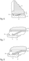
- Fig. 6 to 11 show details and possible designs of the second prestressing elements 47.
- the second prestressing element 47 shown there is again an integral part of the honeycomb support 44 or the canning, wherein both the honeycomb support 44 and the second prestressing element 47, which is designed as a latch-like projection, are each single-walled.
- Fig. 7 a configuration in which the honeycomb support 44 is multi-walled, namely double-walled, and the second prestressing element 47, which is designed as a latch-like projection, is single-walled.
- Fig. 8 which shows a further modification, both the honeycomb support 44 and the second prestressing element 47 shown are each multi-walled.
- the variants shown have the variant of the Fig. 7 the advantage that the fiber mat 45 is supported over its entire axial extent by the honeycomb receiving body 44 and, moreover, the second prestressing element 47 can be easily formed.
- Figs. 6, 7 and 8 refer to second prestressing elements 47, which are designed as an integral part of the honeycomb carrier 44, it should be noted that the variants of the Figs. 6, 7 and 8 also in the exhaust aftertreatment device 40 of the Fig. 1 can be used.
- the single-wall or multi-wall design does not refer to the honeycomb support 44, but rather to the separate prestressing assemblies 46, which provide the prestressing elements 46 and 47.
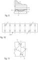
- Fig. 9 shows a modification of the Fig. 6 , in which the second prestressing element 47 shown there is single-walled and designed in the shape of a bridge. This is again an integral part of the honeycomb carrier 44. Also in Fig. 9 The multi-walled nature of the Figs. 7 and 8 can also be used in Fig. 1, 2 a second prestressing element 47 may be designed in bridge form.
- Fig. 10 shows a development of either a separate prestressing assembly 48 or a honeycomb carrier 44 in the region of second prestressing elements 47.
- the second pre-tensioning elements 47 are shown, which are projected radially outwards and, in the installed state, come into contact with the inner surface 49 of the receiving housing 41.
- these second pre-tensioning elements 47 are preferably blade-like projections, wherein these pawl-like projections enclose an angle ⁇ or an angle ⁇ with the flow direction of the respective exhaust gas aftertreatment unit 42.
- the second pre-tensioning elements 47 enclose the angle ⁇ and in the area of the outlet-side end, the second pre-tensioning elements 47 enclose the angle ⁇ with the flow direction of the respective exhaust gas aftertreatment unit 42, wherein the pawl-like projections according to Fig. 10 preferably opposite or offset by 180°. Both angles ⁇ and ⁇ can be the same or different.
- a particularly preferred embodiment is one in which both the angle ⁇ and the angle ⁇ are each 90°.
- the second prestressing elements 47 also advantageously define insertion ramps for the exhaust gas aftertreatment units 42 into the receiving housing 41.
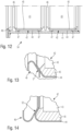
- Fig. 12 shows a further example of an exhaust gas aftertreatment device 54 not according to the invention. Also for Fig. 12
- the same reference numbers are used as in Fig. 1 used.
- the second clamping elements 47 which in turn are designed as latch-like projections and are attached to the wall 49 of the housing 41, are an integral part of the honeycomb support 44 and thus of the canning.
- Fig. 12 the Fig. 3 .
- the first preloading elements 46 acting in the flow direction of the exhaust gas aftertreatment units 42 are in Fig. 12 as in Fig. 1 again designed as separate assemblies, but in contrast to the Fig. 1 a separate first prestressing element 46 is not attached to both axial ends of a respective exhaust gas aftertreatment unit 42, but only to one axial end thereof.
- Fig. 13 shows a detail of the Fig. 6 in the area of two adjacent exhaust aftertreatment units 42.
- the sealing surface 52 between the Fig. 13 shown first prestressing element 46 and an adjacent section of the honeycomb carrier 44 of the adjacent exhaust aftertreatment unit 42 is inclined relative to the radial direction, which runs perpendicular to the flow direction.
- Fig. 14 which is a modification of the detail of the Fig. 13 shows such an inclined position of the sealing surface 52, which, however, in contrast to Fig. 13 is inclined towards the adjacent exhaust aftertreatment unit 42 and not, as in Fig. 13 shown, is tilted away from it.
- Figs. 15 and 16 show further examples of exhaust aftertreatment devices 55 and 56.
- the exhaust aftertreatment units 55 and 56 of the Figs. 15 and 16 basically correspond to the exhaust aftertreatment unit 53 of the Fig. 3 , also in Figs. 15 and 16 Accordingly, the first prestressing elements 46 and the second prestressing elements 47 are designed as integral components of the honeycomb body supports 44 and thus of the respective canning.
- Figs. 15 and 16 differ from that of the Fig. 3 in that the first pre-tensioning elements 46 acting in the flow direction of the respective exhaust gas aftertreatment unit 42 are not designed in the manner of a bellows but rather are formed by a corresponding wall thickness of the honeycomb carrier 44.
- Figs. 15 and 16 differ from each other in that Fig. 16 Adjacent exhaust aftertreatment units 42 do not seal directly against each other in the region of the first prestressing elements 46, but rather against a radially inwardly projecting projection 50 of the receiving housing 41.
- Fig. 17 shows an embodiment of an exhaust gas aftertreatment system 57 according to the invention, which comprises two exhaust gas aftertreatment devices 53 according to Fig. 3
- Each of the two exhaust gas aftertreatment devices 53 has a receiving housing 41 and two exhaust gas aftertreatment units 42 positioned in the receiving housing 41.
- the two exhaust gas aftertreatment devices 53 are connected in series. Exhaust gas, which the exhaust gas aftertreatment system 57 of the Fig. 17 flows through, therefore flows through all exhaust aftertreatment units 42.
- the exhaust aftertreatment system 57 of the Fig. 17 is single-flow.
- a housing 58 is connected between the two exhaust aftertreatment devices 53, which serves, for example, to accommodate sensors such as temperature sensors or pressure sensors. Additionally, the housing 58 can accommodate, for example, a device for introducing a reducing agent into the exhaust gas stream. The housing 58 can also accommodate a soot blower.
- Covers 59 are attached to the opposite ends of the two exhaust gas aftertreatment devices 53, whereby the covers 59 of the exhaust gas aftertreatment system 57 can be connected to exhaust pipes (not shown).
- Figs. 18 and 19 show details of the connection of the receiving housing 41 of one of the Fig. 17 shown exhaust aftertreatment devices 53 with one of the covers 59. With the cover 59 removed (see Fig. 18 ), the corresponding end of the corresponding exhaust gas aftertreatment unit 42 protrudes from the receiving housing 41 with a defined preload stroke VH in the flow direction.
- the prestressing elements 46 of the exhaust gas aftertreatment units 42 arranged in the receiving housing 41 which act in the flow direction, are compressed in order to bring a flange 60 of the cover 59 into contact with a flange 61 of the receiving housing 41 and then to connect the cover 59 and the receiving housing 41 to one another, for example by screwing.
- Fig. 20 shows a cross section through a second exhaust gas aftertreatment system 62, which has only a single exhaust gas aftertreatment device 53, with the covers 59 directly adjoining both sides thereof.
- an intermediate disk 63 is used between the flange 61 of the receiving housing 41 and the flange 60 of the cover 59 to connect the cover 59 to the receiving housing 41 while compressing the first preload elements 46.
- the preload force in the flow direction can be adjusted via the intermediate disk 53.
- Figs. 21, 22 and 23 show details of a third exhaust aftertreatment system 64 with an exhaust aftertreatment device 54 according to Fig. 12 .
- the remaining details are correct Figs. 21, 22 and 23 with the Fig. 20 and with regard to the connection of the cover 59 to the receiving housing 41 with the details of the Figs. 18 and 19 so that the same reference numbers are used for the same assemblies and reference can be made to the above explanations.
- Fig. 17 to 23 also the exhaust aftertreatment devices 40 of the Fig. 1, 2 can be installed in an exhaust aftertreatment system, as well as the exhaust aftertreatment devices 55, 56 of the Figs. 15 and 16 .
- FIG. 17 to 23 details of single-flow exhaust aftertreatment systems 57, 62, 64 show, show Figs. 24, 25 and Figs. 26, 27 and Figs. 28, 29 as well as Fig. 30
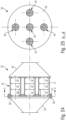
- Figs. 24 and 25 show a multi-flow exhaust aftertreatment system 65, which comprises a total of five parallel-connected exhaust aftertreatment devices 40 according to Fig. 1 includes, but with the difference that Figs. 24 and 25 in the respective housing three exhaust gas aftertreatment units 42 are connected in series and not, as in Fig. 1, 2 only two exhaust aftertreatment units 42.
- FIGs. 24 and 25 A common cover 59 is connected to the respective ends of the five parallel-connected exhaust aftertreatment devices 40.
- a clamping cover 69 is used which is common to all housings 41 of all parallel connected exhaust aftertreatment devices 40 and which also performs the function of the intermediate disc 63 of the Fig. 20 takes over.
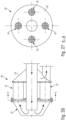
- FIGs. 28 and 29 an exhaust aftertreatment system 67, in which between the left cover 59 and the receiving housings 41 the parallel switched exhaust aftertreatment devices 40, an individual clamping cover 69 is used for each exhaust aftertreatment device 40.
- the inflow side and the outflow side are arranged at opposite ends of the respective exhaust gas aftertreatment system 65, 67.
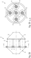
- Figs. 26 and 27 an exhaust aftertreatment system 66, in which the inflow side and outflow side of the exhaust aftertreatment system 26 are formed at the same end or the same side of the exhaust aftertreatment system 66.
- FIGs. 26 and 27 Four exhaust aftertreatment devices 40 are connected in parallel, namely between the covers 59. While in Figs. 24 and 25 one of the covers 59 forms an inlet side and the opposite cover 59 forms an outlet side of the respective exhaust gas aftertreatment system, are in Figs. 26 and 27 Inlet side and outlet side on the right cover 59 of the Fig. 6 At the opposite cover 59, a flow reversal for the exhaust gas takes place. Such a flow reversal for the exhaust gas is already known from the DE 10 2016 205 327 A1 known. In Fig. 26 Arrows illustrate the exhaust gas flow through the exhaust aftertreatment system 66 of the Figs. 26 and 27 .
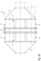
- Fig. 30 shows an exhaust gas aftertreatment system 68 in which two exhaust gas aftertreatment devices 14 are arranged in series one behind the other and several such series circuits are arranged parallel to one another between two covers 59.
- a housing 58 for accommodating a sensor system or for accommodating soot blowers or for accommodating introducing devices for reducing agents can be arranged.
- the flow of the exhaust gas can be either as in Figs. 24, 25 or as in Figs. 26, 27 be executed.
- the series-connected exhaust gas aftertreatment units 42 can be identical or different.
- the two left-hand exhaust aftertreatment units 42 are designed as particulate filters, and the two right-hand exhaust aftertreatment units 42 are designed as SCR catalysts or NOx storage catalysts. It is also possible to leave a position of an exhaust aftertreatment unit 42 free and simply arrange a placeholder there, which cannot perform any exhaust aftertreatment function.
- the prestressing forces for the prestressing elements 46, 47 can be adjusted, in particular, by selecting the material and/or the wall thickness and/or the geometry and/or the number of walls of the prestressing elements 46, 47. As explained above, the prestressing elements 46, 47 can be single-walled or multi-walled.
- the number of bellows or corrugations in the bellows-like prestressing elements 46 can be varied.
- the number of bellows or corrugations in the pawl-like prestressing elements 47 can be varied.
- An exhaust aftertreatment system can be expanded as needed from the above-described components of the housing 41, exhaust aftertreatment units 42, housing 58, and cover 59 in a modular system.
- Housing 41 and exhaust aftertreatment units 42 can be designed with coarse tolerances.
- the preloading elements 26, 27 compensate for such tolerances.
- the preloading elements 26, 27 also provide vibration damping and reduce vibrations in the exhaust system.
Landscapes
- Engineering & Computer Science (AREA)
- Chemical & Material Sciences (AREA)
- Chemical Kinetics & Catalysis (AREA)
- Combustion & Propulsion (AREA)
- Mechanical Engineering (AREA)
- General Engineering & Computer Science (AREA)
- Health & Medical Sciences (AREA)
- Toxicology (AREA)
- Exhaust Gas After Treatment (AREA)
- Processes For Solid Components From Exhaust (AREA)
- Exhaust Gas Treatment By Means Of Catalyst (AREA)
- Catalysts (AREA)
Description
- Die Erfindung betrifft ein Abgasnachbehandlungssystem einer Brennkraftmaschine nach dem Oberbegriff des Anspruchs 1.
- Die hier vorliegende Erfindung betrifft den Bereich sogenannter Großbrennkraftmaschinen, deren Zylinder Kolbendurchmesser von mindestens 140 mm, insbesondere von mindestens 175 mm, aufweisen. Bei solchen Großbrennkraftmaschinen handelt es sich zum Beispiel um Schiffsmotoren. Solche Großbrennkraftmaschinen können als Dieselmotoren, Gasmotoren oder Dual-Fuel-Motoren ausgeführt sein. In Dual-Fuel-Motoren kann in einem ersten Betriebszustand ein flüssiger Kraftstoff, insbesondere ein Dieselkraftstoff, und in einem zweiten Betriebszustand ein gasförmiger Kraftstoff, insbesondere Erdgas, verbrannt werden.
- Auch im Bereich der Großbrennkraftmaschinen kommt der Abgasnachbehandlung eine immer wichtigere Rolle zu. So ist aus der
DE 10 2016 205 327 A1 ein Abgasnachbehandlungssystem beschrieben, wie es bei Großbrennkraftmaschinen zum Einsatz kommen kann. Das dort offenbarte Abgasnachbehandlungssystem verfügt über einen Reaktorraum, wobei im Reaktorraum ein SCR-Katalysator angeordnet ist. Es ist es bekannt, dass ein solcher SCR-Katalysator mehrere von Abgas durchströmte, parallel geschaltete Abgasnachbehandlungseinheiten aufweist, wobei jede Abgasnachbehandlungseinheit einen Wabenkörper aufweist, der von einem Wabenkörperträger gehalten ist und über den Wabenkörperträger in einem Aufnahmegehäuse angeordnet ist. Der Wabenkörperträger wird auch als Canning bezeichnet, welcher den jeweiligen Wabenkörper unter Freilassen von Stirnseiten desselben außen umgibt. - Bislang bereitet das Anordnen der Abgasnachbehandlungseinheiten im Aufnahmegehäuse dahingehend Schwierigkeiten, dass nur mit großem Aufwand sichergestellt werden kann, dass das Abgas auch vollständig den Wabenkörper durchströmt und nicht über Spalte zwischen dem Wabenkörperträger und dem Aufnahmegehäuse am Wabenkörper vorbeiströmt.
-
EP 3 147 472 A1 offenbart ein Abgasnachbehandlungssystem einer Brennkraftmaschine nach dem Oberbegriff des Anspruchs 1. -
DE 22 36 592 A1 undDE 34 06 721 A1 offenbaren weiteren Stand der Technik. - Hiervon ausgehend liegt der Erfindung die Aufgabe zugrunde, ein neuartiges Abgasnachbehandlungssystem einer Brennkraftmaschine zu schaffen.
- Diese Aufgabe wird durch ein Abgasnachbehandlungssystemvorrichtung nach Anspruch 1 gelöst.
- Über die in Durchströmungsrichtung und senkrecht zur Durchströmungsrichtung der jeweiligen Abgasnachbehandlungseinheit wirkenden Vorspannelemente kann sichergestellt werden, dass das Abgas durch den mindestens einen Wabenkörper der mindestens einen Abgasnachbehandlungseinheit geleitet wird und nicht über Spalte zwischen dem Wabenkörperträger des jeweiligen Wabenkörpers und dem Aufnahmegehäuse am Wabenkörper vorbeiströmt. Über die in Durchströmungsrichtung der jeweiligen Abgasnachbehandlungseinheit wirkenden ersten Vorspannelemente und die senkrecht zur Durchströmungsrichtung der jeweiligen Abgasnachbehandlungseinheit wirkenden zweiten Vorspannelemente kann dies mit geringem Aufwand bewerkstelligt werden.
- Vorzugsweise sind die in Durchströmungsrichtung der jeweiligen Abgasnachbehandlungseinheit wirkenden ersten Vorspannelemente und die senkrecht zur Durchströmungsrichtung der jeweiligen Abgasnachbehandlungseinheit wirkenden zweiten Vorspannelemente von separaten Vorspannbaugruppen ausgebildet sind, wobei jede separate Vorspannbaugruppe ein in Durchströmungsrichtung der jeweiligen Abgasnachbehandlungseinheit wirkendes erstes Vorspannelement und mehrere senkrecht zur Durchströmungsrichtung der jeweiligen Abgasnachbehandlungseinheit wirkende zweiten Vorspannelemente aufweist, und wobei die separaten Vorspannbaugruppen an mindestens einem von sich gegenüberliegenden axialen Enden der jeweiligen Abgasnachbehandlungseinheit auf dieselbe aufgesteckt sind, nämlich auf den Wabenkörperträger der jeweiligen Abgasnachbehandlungseinheit. Dann, wenn die Vorspannelemente von separaten Vorspannbaugruppen ausgebildet sind, die auf die jeweilige Abgasnachbehandlungseinheit aufgesteckt sind, können die Vorspannbaugruppen wiederverwendet werden, insbesondere dann, wenn eine Abgasnachbehandlungseinheit, zum Beispiel infolge eines verblockten Wabenkörpers, ausgetauscht werden muss.
- Vorzugsweise sind die in Durchströmungsrichtung der jeweiligen Abgasnachbehandlungseinheit wirkenden ersten Vorspannelemente als faltenbalgartige Vorspannelemente ausgebildet. Über faltenbalgartige Vorspannelemente kann die Vorspannung der jeweiligen Abgasnachbehandlungseinheit in Durchströmungsrichtung der jeweiligen Abgasnachbehandlungseinheit einfach und vorteilhaft bereitgestellt werden.
- Vorzugsweise sind die senkrecht zur Durchströmungsrichtung der jeweiligen Abgasnachbehandlungseinheit wirkenden zweiten Vorspannelemente als klinkenartige Ausstellungen ausgebildet sind. Über klinkenartige Ausstellungen kann die Vorspannung der jeweiligen Abgasnachbehandlungseinheit senkrecht zur Durchströmungsrichtung der jeweiligen Abgasnachbehandlungseinheit einfach und zuverlässig bereitgestellt werden.
- Vorzugsweise schließen die klinkenartigen Ausstellungen mit der Durchströmungsrichtung einen Winkel von 90° ein. Dann, wenn die klinkenartigen Ausstellungen mit der Durchströmungsrichtung einen Winkel von 90° einschließen, lässt sich die jeweilige Abgasnachbehandlungseinheit zusammen mit den Vorspannelementen besonders vorteilhaft im Aufnahmegehäuse anordnen.
- Vorzugsweise sind Dichtflächen an den in Durchströmungsrichtung der jeweiligen Abgasnachbehandlungseinheit wirkenden ersten Vorspannelementen senkrecht zur Durchströmungsrichtung der jeweiligen Abgasnachbehandlungseinheit ausgerichtet. Dies insbesondere dann von Vorteil, wenn in einem Aufnahmegehäuse mehrere Abgasnachbehandlungseinheiten im Sinne einer Reihenschaltung hintereinander angeordnet sind. In diesem Fall sorgt dann eine Fertigungstoleranz im Bereich der Abgasnachbehandlungseinheit für keine Beeinträchtigung der Dichtwirkung an den Dichtflächen.
- Bevorzugte Weiterbildungen der Erfindung ergeben sich aus den Unteransprüchen und der nachfolgenden Beschreibung. Ausführungsbeispiele der Erfindung werden, ohne hierauf beschränkt zu sein, an Hand der Zeichnung näher erläutert. Dabei zeigt:
- Fig. 1
- einen Querschnitt durch ein Beispiel einer nicht erfindungsgemäßen Abgasnachbehandlungsvorrichtung einer Brennkraftmaschine,
- Fig. 2
- ein Detail der
Fig. 1 in Explosionsdarstellung, - Fig. 3
- einen Querschnitt durch ein Beispiel einer weiteren nicht erfindungsgemäßen Abgasnachbehandlungsvorrichtung einer Brennkraftmaschine,
- Fig. 4
- ein Detail der
Fig. 3 , - Fig. 5
- eine Alternative zum Detail der
Fig. 4 , - Fig. 6
- ein weiteres Detail der
Fig. 3 , - Fig. 7
- eine Alternative zum Detail der
Fig. 6 , - Fig. 8
- eine weitere Alternative zum Detail der
Fig. 6 , - Fig. 9
- eine weitere Alternative zum Detail der
Fig. 6 , - Fig. 10
- ein weiteres Detail der
Fig. 1 oder3 , - Fig. 11
- einen Ausschnitt aus einer Alternative zum Detail der
Fig. 10 ; - Fig. 12
- einen Querschnitt durch ein weiteres Beispiel einer nicht erfindungsgemäßen Abgasnachbehandlungsvorrichtung einer Brennkraftmaschine,
- Fig. 13
- ein Detail der
Fig. 12 , - Fig. 14
- eine Alternative zum Detail der
Fig. 13 , - Fig. 15
- einen Querschnitt durch ein weiteres Beispiel einer nicht erfindungsgemäßen Abgasnachbehandlungsvorrichtung einer Brennkraftmaschine,
- Fig. 16
- einen Querschnitt durch ein weiteres Beispiel einer nicht erfindungsgemäßen Abgasnachbehandlungsvorrichtung einer Brennkraftmaschine,
- Fig. 17
- einen Querschnitt durch ein Beispiel eines erfindungsgemäßen Abgasnachbehandlungssystems einer Brenn-kraftmaschine,
- Fig. 18
- ein Detail der
Fig. 17 in Explosionsdarstellung, - Fig. 19
- das Detail der
Fig. 18 im Zusammenbau, - Fig. 20
- einen Querschnitt durch ein Beispiel eines nicht erfindungsgemäßen Abgasnachbehandlungssystems einer Brenn-kraftmaschine,
- Fig. 21
- einen Querschnitt durch ein Beispiel eines nicht erfindungsgemäßen Abgasnachbehandlungssystems einer Brenn-kraftmaschine,
- Fig. 22
- ein Detail der
Fig. 21 , - Fig. 23
- ein Explosionsdarstellung der
Fig. 22 , - Fig. 24
- einen Querschnitt durch ein weiteres Beispiel eines nicht erfindungsgemäßen Abgasnachbehandlungssystems einer Brennkraftmaschine,
- Fig. 25
- den Querschnitt A-A der
Fig. 24 , - Fig. 26
- einen Querschnitt durch ein weiteres Beispiel eines nicht erfindungsgemäßen Abgasnachbehandlungssystems einer Brennkraftmaschine,
- Fig. 27
- den Querschnitt B-B der
Fig. 26 , - Fig. 28
- einen Querschnitt durch ein weiteres Beispiel eines nicht erfindungsgemäßen Abgasnachbehandlungssystems einer Brennkraftmaschine,
- Fig. 29
- den Querschnitt C-C der
Fig. 28 , - Fig. 30
- eine Seitenansicht eines weiteren Beispiels eines nicht erfindungsgemäßen Abgasnachbehandlungssystems einer Brennkraftmaschine.
- Die Erfindung betrifft ein Abgasnachbehandlungssystem einer Brennkraftmaschine, insbesondere einer Großbrennkraftmaschine. Bei einer Großbrennkraftmaschine handelt es sich insbesondere um einen Schiffsmotor, der als Dieselmotor, Gasmotor oder Dual-Fuel-Motor ausgeführt sein kann. Eine Großbrennkraftmaschine verfügt über Zylinder mit einem Kolbendurchmesser von mindestens 140 mm, insbesondere von mindestens 175 mm.
-
Fig. 1 zeigt Details einer nicht erfindungsgemäßen Abgasnachbehandlungsvorrichtung 40. Die Abgasnachbehandlungsvorrichtung 40 verfügt über ein Aufnahmegehäuse 41 sowie im gezeigten Beispiel über mehrere im Aufnahmegehäuse 41 angeordnete Abgasnachbehandlungseinheiten 42. InFig. 1 sind zwei in Reihe hintereinander geschaltete Abgasnachbehandlungseinheiten 42 gezeigt, die beide im Aufnahmegehäuse 41 angeordnet sind. - Das Aufnahmegehäuse 41 ist in
Fig. 1, 2 rohrartig ausgebildet. Eine Durchströmungsrichtung des Aufnahmegehäuses 41 bzw. der im Aufnahmegehäuse 41 angeordneten Abgasnachbehandlungseinheiten 42 erstreckt sich in Axialrichtung derselben. Dann, wenn das rohrartige Aufnahmegehäuse 41 und die im Aufnahmegehäuse 41 angeordneten Abgasnachbehandlungseinheiten 42 im Querschnitt kreisrund ausgebildet sind, erstreckt sich die Radialrichtung des Aufnahmegehäuses 41 bzw. der im Aufnahmegehäuse 41 angeordneten Abgasnachbehandlungseinheiten 42 senkrecht zur Durchströmungsrichtung derselben. Die Querschnitte von Aufnahmegehäuse 41 und Abgasnachbehandlungseinheiten 42 können auch rechteckig, quadratisch, oval oder dergleichen sein. - Jede Abgasnachbehandlungseinheit 42 verfügt über einen als Katalysator und/oder als Partikelfilter dienenden Wabenkörper 43 sowie über einen den Wabenkörper 43 außen umgebenden, an den Stirnseiten desselben den Wabenkörper 43 freilassenden Wabenkörperträger 44. Der Wabenkörperträger 44 wird auch als Canning bezeichnet. Gemäß
Fig. 1 und 2 ist zwischen dem Wabenkörper 43 und dem Wabenkörperträger 44 der dort gezeigten Abgasnachbehandlungseinheiten 42 eine Fasermatte 45 angeordnet. Auch die Fasermatte 45 lässt Stirnseiten des jeweiligen Wabenkörpers 43, die eine Eintrittsseite und eine Austrittsseite für das Abgas definieren, frei. - Die jeweilige Abgasnachbehandlungseinheit 43 ist über Vorspannelemente vorgespannt im Aufnahmegehäuse 41 aufgenommen.
- So ist die jeweilige Abgasnachbehandlungseinheit 42 sowohl über in Durchströmungsrichtung der Abgasnachbehandlungseinheit 42 wirkende erste Vorspannelemente 46 als auch über senkrechte zur Durchströmungsrichtung der jeweiligen Abgasnachbehandlungseinheit 42 wirkende zweite Vorspannelemente 47 vorgespannt im Aufnahmegehäuse 41 positioniert. Die Vorspannelemente 46, 47 bewirken eine federelastische Vorspannung der jeweiligen Abgasnachbehandlungseinheit 42 im Aufnahmegehäuse 41 in Durchströmungsrichtung sowie senkrecht zur Durchströmungsrichtung.
- In
Fig. 1 und 2 sind die in Durchströmungsrichtung bzw. in Axialrichtung der jeweiligen Abgasnachbehandlungseinheit 42 wirkenden ersten Vorspannelemente 46 und die senkrecht zur Durchströmungsrichtung bzw. in Radialrichtung der jeweiligen Abgasnachbehandlungseinheit 42 wirkenden zweiten Vorspannelemente 47 von separaten Vorspannbaugruppen 48 ausgebildet. - Diese separaten Vorspannbaugruppen 48 können insbesondere der Explosionsdarstellung der
Fig. 2 entnommen werden. Jede separate Vorspannbaugruppe 48 weist ein in Durchströmungsrichtung der jeweiligen Abgasnachbehandlungseinheit 42 wirkendes erstes Vorspannelement 46 und mehrere senkrecht zur Durchströmungsrichtung der jeweiligen Abgasnachbehandlungseinheit 42 wirkende zweite Vorspannelemente 47 auf. - Die separaten Vorspannbaugruppen 48 sind in
Fig. 1, 2 an sich gegenüberliegenden axialen Enden der jeweiligen Abgasnachbehandlungseinheit 42 auf dieselbe aufgesteckt, nämlich auf den Wabenkörperträger 44 der jeweiligen Abgasnachbehandlungseinheit 42, wiederum unter Freilassen der Stirnseiten des jeweiligen Wabenkörpers 43, welche die Eintrittsseite und die Austrittsseite des jeweiligen Wabenkörpers 43 und damit der jeweiligen Abgasnachbehandlungseinheit 42 für das zu reinigende Abgas dienen. - Dann, wenn das Aufnahmegehäuse 41 in Durchströmungsrichtung gesehen im Querschnitt kreisrund ausgebildet, sind auch die Abgasnachbehandlungseinheiten 42 und die separaten Vorspannbaugruppen 48 im Querschnitt kreisrund ausgebildet. In diesem Fall sind dann über den Umfang der Vorspannelemente 48 mehrere zweite Vorspannelemente 47, die dann der Vorspannung in Radialrichtung dienen, verteilt.
- Die Querschnittskontur von Aufnahmegehäuse 41 und Abgasnachbehandlungseinheiten 42 kann auch rechteckig, quadratisch, oval oder dergleichen sein.
- In
Fig. 1 und 2 sind die in Durchströmungsrichtung der jeweiligen Abgasnachbehandlungseinheit 42 wirkenden ersten Vorspannelemente 46 als faltenbalgartige Vorspannelemente ausgebildet. - Die senkrecht zur Durchströmungsrichtung der jeweiligen Abgasnachbehandlungseinheit 42 wirkenden zweiten Vorspannelemente 47 sind als klinkenartige Ausstellungen ausgebildet, die nach radial außen aus der jeweiligen Vorspannbaugruppe 48 herausgebogen sind. Diese, vorzugsweise als klinkenartige Ausstellungen ausgebildeten, zweiten Vorspannelemente 47 stützen sich auf einer Innenwand 49 des Aufnahmegehäuses 41 ab.
- Die in Durchströmungsrichtung der jeweiligen Abgasnachbehandlungseinheit 42 wirkenden, vorzugsweise als Faltenbalge ausgebildeten ersten Vorspannelemente 46 stützen sich dann, wenn sich an eine Abgasnachbehandlungseinheit 42 eine weitere Abgasnachbehandlungseinheit 42 anschließt, an einem angrenzenden ersten Vorspannelement 46 der angrenzenden Abgasnachbehandlungseinheit 42 ab. Anderenfalls stützen sich diese ersten Vorspannelemente 46, die faltenbalgartig ausgebildet sind, an einem sich nach radial innen erstreckenden Vorsprung 50 des Aufnahmegehäuses 41 ab.
- Wie
Fig. 2 entnommen werden kann, sind an den separaten Vorspannbaugruppen 48 nicht nur die nach außen ausgestellten zweiten Vorspannelemente 47 ausgebildet, sondern darüber hinaus auch nach radial innen ausgestellte dritte Vorspannelemente 51. Diese nach radial innen ausgestellten, dritten Vorspannelemente 51 dienen der vorspannenden Aufnahme der Abgasnachbehandlungseinheit 42 in den separaten Vorspannbaugruppen 48. Diese nach radial innen ausgestellten Vorspannelemente 51 stützen sich demnach auf dem Wabenkörperträger 44 der jeweiligen Abgasnachbehandlungseinheit 42 federelastisch ab. - Gemäß
Fig. 1 verlaufen Dichtflächen 52 an den in Durchströmungsrichtung wirkenden ersten Vorspannelementen 46 senkrecht zur Durchströmungsrichtung der jeweiligen Abgasnachbehandlungseinheit 42. Dies ist von Vorteil, um zu vermeiden, dass Fertigungstoleranzen im Bereich der Abgasnachbehandlungseinheiten 42 die Dichtwirkung zwischen aneinander angrenzenden ersten Vorspannelementen 46 aneinander angrenzender Abgasnachbehandlungseinheiten 42 beeinträchtigen. -
Fig. 3 zeigt einen ausschnittsweisen Querschnitt durch eine weitere nicht erfindungsgemäße Abgasnachbehandlungsvorrichtung 53, die hinsichtlich ihres grundsätzlichen Aufbaus der Abgasnachbehandlungsvorrichtung 40 derFig. 1 entspricht. Daher werden für gleiche Baugruppen gleiche Bezugsziffern verwendet und es wird nachfolgend unter Bezugnahme aufFig. 3 auf solche Details eingegangen, durch die sich die Abgasnachbehandlungsvorrichtung 53 derFig. 3 von der Abgasnachbehandlungseinheit 40 derFig. 1 unterscheidet. Während inFig. 1 die ersten Vorspannelemente 46 und die zweiten Vorspannelemente 47 beide von separaten Vorspannbaugruppen 48 bereitgestellt sind, sind inFig. 3 sowohl die ersten Vorspannelemente 46 als auch die zweiten Vorspannelemente 47 als integraler Bestandteil des Wabenkörperträgers 44 und damit des Canning ausgebildet. Damit reduziert sich zwar die Anzahl der einzelnen Baugruppen, bei Austausch einer Abgasnachbehandlungseinheit 42 können jedoch die Vorspannelemente 46, 47 nicht wiederverwendet werden. -
Fig. 4 , die ein Detail derFig. 3 im Bereich der aneinander angrenzenden ersten Vorspannelemente 46 der einander angrenzenden Abgasnachbehandlungseinheiten 42 zeigt, kann entnommen werden, dass die Dichtflächen 52 der ersten Vorspannelemente 46 senkrecht zu der Durchströmungsrichtung der Abgasnachbehandlungseinheiten 42 verlaufen. - Demgegenüber zeigt
Fig. 5 eine Abwandlung für das Detail derFig. 4 , bei welcher die Dichtflächen 52 der aneinander angrenzenden ersten Vorspannelemente 46 von aneinander angrenzenden Abgasnachbehandlungseinheiten 42 nicht senkrecht zur Durchströmungsrichtung der jeweiligen Abgasnachbehandlungseinheiten 42 verlaufen, sondern vielmehr gegenüber der Radialrichtung, die senkrecht zur Durchströmungsrichtung verläuft, schräg gestellt sind. -
Fig. 6 bis 11 zeigen Details und mögliche Ausführungen der zweiten Vorspannelemente 47. So ist inFig. 6 gezeigt, dass das dort gezeigte zweite Vorspannelement 47 wieder integraler Bestandteil des Wabenkörperträgers 44 bzw. des Canning ist, wobei sowohl der Wabenkörperträger 44 als auch das zweite Vorspannelement 47, welches als klinkenartige Ausstellung ausgebildet ist, jeweils einwandig ausgebildet sind. Demgegenüber zeigtFig. 7 eine Ausgestaltung, bei welcher der Wabenkörperträger 44 mehrwandig, nämlich zweiwandig, ausgebildet und das zweite Vorspannelement 47, welches als klinkenartige Ausstellung ausgebildet ist, einwandig ausgebildet ist. InFig. 8 , die eine weitere Abwandlung zeigt, sind sowohl der Wabenkörperträger 44 als auch das gezeigte zweite Vorspannelement 47 jeweils mehrwandig ausgebildet. Von den inFig. 6, 7 und 8 gezeigten Varianten verfügt die Variante derFig. 7 über den Vorteil, dass der Fasermatte 45 über seine gesamte axiale Erstreckung vom Wabenaufnahmekörper 44 gestützt ist und darüber hinaus einfach das zweite Vorspannelement 47 ausgebildet werden kann. - Obwohl sich
Fig. 6, 7 und 8 auf zweite Vorspannelemente 47 beziehen, die als integraler Bestandteil des Wabenkörperträgers 44 ausgebildet sind, sei darauf hingewiesen, dass die Varianten derFig. 6, 7 und 8 auch bei der Abgasnachbehandlungsvorrichtung 40 derFig. 1 zum Einsatz kommen können. Hier bezieht sich dann die Einwandigkeit oder Mehrwandigkeit nicht auf den Wabenkörperträger 44, sondern vielmehr auf die separaten Vorspannbaugruppen 46, welche die Vorspannelemente 46 und 47 bereitstellen. -
Fig. 9 zeigt eine Abwandlung derFig. 6 , in welcher das dort gezeigte zweite Vorspannelement 47 einwandig und in Brückenform ausgebildet ist. Dieses ist wieder integraler Bestandteil des Wabenkörperträgers 44. Auch inFig. 9 kann die Mehrwandigkeit derFig. 7 und 8 zum Einsatz kommen. Auch kann inFig. 1, 2 ein zweites Vorspannelement 47 in Brückenform ausgeführt sein. -
Fig. 10 zeigt eine Abwicklung entweder einer separaten Vorspannbaugruppe 48 oder eines Wabenkörperträgers 44 im Bereich von zweiten Vorspannelemente 47. InFig. 10 sind lediglich die zweiten Vorspannelemente 47 gezeigt, die nach radial außen ausgestellt sind und im verbauten Zustand an der Innenfläche 49 des Aufnahmegehäuses 41 zur Anlage kommen. Bei diesen zweiten Vorspannelementen 47 handelt es sich, wie bereits ausgeführt, vorzugsweise um klingenartige Ausstellungen, wobei diese klinkenartigen Ausstellungen mit der Durchströmungsrichtung der jeweiligen Abgasnachbehandlungseinheit 42 einen Winkel α bzw. einen Winkel β einschließen. Im Bereich des eintrittsseitigen Endes der jeweiligen Abgasnachbehandlungseinheit 42 schließen die zweiten Vorspannelemente 47 den α und im Bereich des austrittsseitigen Endes schließen die zweiten Vorspannelemente 47 den Winkel β mit der Durchströmungsrichtung der jeweiligen Abgasnachbehandlungseinheit 42 ein, wobei die klinkenartigen Ausstellungen gemäßFig. 10 vorzugsweise gegenläufig bzw. um 180° zueinander versetzt sind. Der Winkel α als auch der Winkel β können gleich groß aber auch unterschiedlich groß sein. - Besonders bevorzugt ist eine Ausführung, in welcher sowohl der Winkel α als auch der Winkel β jeweils 90° betragen. In diesem Fall definieren die zweiten Vorspannelemente 47 dann auch in vorteilhafter Weise Einführrampen für die Abgasnachbehandlungseinheiten 42 in das Aufnahmegehäuse 41.
-
Fig. 12 zeigt ein weiteres Beispiel einer nicht erfindungsgemäßen Abgasnachbehandlungsvorrichtung 54. Auch fürFig. 12 werden für gleiche Baugruppen gleiche Bezugsziffern wie inFig. 1 verwendet. InFig. 12 sind die zweiten Spannelemente 47, die wiederum als klinkenartige Ausstellungen ausgebildet sind und an der Wand 49 des Aufnahmegehäuses 41 zur Anlage kommen, integraler Bestandteil des Wabenkörperträgers 44 und damit des Canning. Insofern entsprichtFig. 12 derFig. 3 . Die ersten in Durchströmungsrichtung der Abgasnachbehandlungseinheiten 42 wirkenden ersten Vorspannelemente 46 sind jedoch inFig. 12 wie inFig. 1 wiederum als separate Baugruppen ausgeführt, wobei jedoch im Unterschied zurFig. 1 nicht an beiden axialen Enden einer jeweiligen Abgasnachbehandlungseinheit 42 ein separates erstes Vorspannelement 46 aufgesteckt ist, sondern lediglich an einem axialen Ende derselben. -
Fig. 13 zeigt ein Detail derFig. 6 im Bereich von zwei aneinander angrenzenden Abgasnachbehandlungseinheiten 42. Dabei ist gemäßFig. 13 die Dichtfläche 52 zwischen dem inFig. 13 gezeigten ersten Vorspannelement 46 und einem angrenzenden Abschnitt des Wabenkörperträgers 44 der angrenzenden Abgasnachbehandlungseinheit 42 gegenüber der Radialrichtung, die senkrecht zur Durchströmungsrichtung verläuft, schräg gestellt. AuchFig. 14 , die eine Abwandlung des Details derFig. 13 zeigt, zeigt eine derartige Schrägstellung der Dichtfläche 52, die jedoch im Unterschied zurFig. 13 in Richtung auf die angrenzende Abgasnachbehandlungseinheit 42 zugeneigt ist und nicht, wie inFig. 13 gezeigt, von derselben weggeneigt ist. -
Fig. 15 und 16 zeigen weitere Beispiele von Abgasnachbehandlungsvorrichtungen 55 und 56. Die Abgasnachbehandlungseinheiten 55 und 56 derFig. 15 und 16 entsprechen grundsätzlich der Abgasnachbehandlungseinheit 53 derFig. 3 , auch inFig. 15 und 16 sind demnach die ersten Vorspannelemente 46 und die zweiten Vorspannelemente 47 als integrale Bestandteile der Wabenkörperträger 44 und damit des jeweiligen Canning ausgebildet. - Die Beispiele der
Fig. 15 und 16 unterscheiden sich jedoch von dem derFig. 3 dadurch, dass die ersten, in Durchströmungsrichtung der jeweiligen Abgasnachbehandlungseinheit 42 wirksamen Vorspannelemente 46 nicht faltenbalgartig ausgebildet sind, sondern vielmehr durch eine entsprechende Wandstärke des Wabenkörperträgers 44 ausgebildet sind. - Die
Fig. 15 und 16 unterscheiden sich untereinander dadurch, dass inFig. 16 aneinander angrenzende Abgasnachbehandlungseinheiten 42 nicht unmittelbar gegeneinander im Bereich der ersten Vorspannelemente 46 abdichten, sondern vielmehr gegenüber einem nach radial innen vorstehenden Vorsprung 50 des Aufnahmegehäuses 41. -
Fig. 17 zeigt ein Ausführungsbeispiel eines erfindungsgemäßen Abgasnachbehandlungssystems 57, welches zwei Abgasnachbehandlungsvorrichtungen 53 gemäßFig. 3 umfasst. Jede der beiden Abgasnachbehandlungsvorrichtungen 53 verfügt über ein Aufnahmegehäuse 41 sowie zwei im Aufnahmegehäuse 41 positionierte Abgasnachbehandlungseinheiten 42. - Die beiden Abgasnachbehandlungsvorrichtungen 53 sind in Reihe hintereinandergeschaltet. Abgas, welches das Abgasnachbehandlungssystem 57 der
Fig. 17 durchströmt, strömt demnach durch alle Abgasnachbehandlungseinheiten 42. Das Abgasnachbehandlungssystem 57 derFig. 17 ist einflutig. - Gemäß
Fig. 17 ist zwischen die beiden Abgasnachbehandlungsvorrichtungen 53 ein Gehäuse 58 geschaltet, welches zum Beispiel der Aufnahme von Sensoren, wie zum Beispiel Temperatursensoren oder auch Drucksensoren, dient. Zusätzlich kann das Gehäuse 58 zum Beispiel eine Vorrichtung aufnehmen, um ein Reduktionsmittel in den Abgasstrom einzubringen. Auch kann das Gehäuse 58 einen Rußbläser aufnehmen. - An den voneinander abgewandten Enden der beiden Abgasnachbehandlungsvorrichtungen 53 schließen sich Deckel 59 an, wobei über die Deckel 59 des Abgasnachbehandlungssystems 57 an Abgasleitungen (nicht gezeigt) angeschlossen werden kann.
-
Fig. 18 und 19 zeigen Details der Verbindung des Aufnahmegehäuses 41 einer der inFig. 17 gezeigten Abgasnachbehandlungsvorrichtungen 53 mit einem der Deckel 59. Bei demontiertem Deckel 59 (sieheFig. 18 ) steht das entsprechende Ende der entsprechenden Abgasnachbehandlungseinheit 42 mit einem definierten Vorspannhub VH in Durchströmungsrichtung aus dem Aufnahmegehäuse 41 heraus. - Bei montiertem Deckel 59 (siehe
Fig. 19 ) werden die in Durchströmungsrichtung wirksamen Vorspannelemente 46 der im Aufnahmegehäuse 41 angeordneten Abgasnachbehandlungseinheiten 42 komprimiert, um einen Flansch 60 des Deckels 59 an einem Flansch 61 des Aufnahmegehäuses 41 zur Anlage zu bringen und dann Deckel 59 und Aufnahmegehäuse 41 zum Beispiel durch Verschrauben miteinander zu verbinden. -
Fig. 20 zeigt einen Querschnitt durch ein zweites Abgasnachbehandlungssystem 62, welches lediglich eine einzige Abgasnachbehandlungsvorrichtung 53 aufweist, wobei sich zu beiden Seiten derselben unmittelbar die Deckel 59 anschließen. - In
Fig. 20 kommt am linken Ende der Abgasnachbehandlungsvorrichtung 53 zwischen dem Flansch 61 des Aufnahmegehäuses 41 und dem Flansch 60 des Deckels 59 eine Zwischenscheibe 63 zum Einsatz, um den Deckel 59 an dem Aufnahmegehäuse 41 unter Komprimieren der ersten Vorspannelemente 46 zu verbinden. Über die Zwischenscheibe 53 kann die Vorspannkraft in Durchströmungsrichtung eingestellt werden. -
Fig. 21, 22 und 23 zeigen Details eines dritten Abgasnachbehandlungssystems 64 mit einer Abgasnachbehandlungsvorrichtung 54 gemäßFig. 12 . Hinsichtlich aller übrigen Details stimmt jedochFig. 21, 22 und 23 mit derFig. 20 und im Hinblick auf die Verbindung des Deckels 59 mit dem Aufnahmegehäuse 41 mit den Details derFig. 18 und 19 überein, sodass wiederum für gleiche Baugruppen gleiche Bezugsziffern verwendet werden und auf die obigen Ausführungen verwiesen werden kann. - Es sei darauf hingewiesen, dass in
Fig. 17 bis 23 auch die Abgasnachbehandlungsvorrichtungen 40 derFig. 1, 2 in einem Abgasnachbehandlungssystem verbaut werden können, ebenso die Abgasnachbehandlungsvorrichtungen 55, 56 derFig. 15 und 16 . - Während
Fig. 17 bis 23 jeweils Details einflutiger Abgasnachbehandlungssysteme 57, 62, 64 zeigen, zeigenFig. 24, 25 undFig. 26, 27 undFig. 28, 29 sowieFig. 30 jeweils unterschiedliche Ansichten mehrflutiger Abgasnachbehandlungssysteme 65, 66, 67 und 68.Fig. 24 und 25 zeigen ein mehrflutigen Abgasnachbehandlungssystems 65, welches insgesamt fünf parallel geschaltete Abgasnachbehandlungsvorrichtungen 40 gemäßFig. 1 umfasst, jedoch mit dem Unterschied, dass beiFig. 24 und 25 im jeweiligen Aufnahmegehäuse jeweils drei Abgasnachbehandlungseinheit 42 in Reihe hintereinandergeschaltet sind und nicht, wie inFig. 1, 2 lediglich zwei Abgasnachbehandlungseinheiten 42. - In
Fig. 24 und 25 schließt sich zu den jeweiligen Enden der fünf parallel geschalteten Abgasnachbehandlungsvorrichtungen 40 jeweils ein gemeinsamer Deckel 59 an. Dabei kommt InFig. 24 und 25 zwischen dem Flansch 60 des linken Deckels 59 und dem Flansch 61 der Aufnahmegehäuse 41 ein für alle Aufnahmegehäuse 41 aller parallel geschalteter Abgasnachbehandlungsvorrichtungen 40 gemeinsamer Spanndeckel 69 zum Einsatz, der auch die Funktion der Zwischenscheibe 63 derFig. 20 übernimmt. - Demgegenüber zeigen
Fig. 28 und 29 ein Abgasnachbehandlungssystem 67, bei welchem zwischen dem linken Deckel 59 und den Aufnahmegehäusen 41 der parallel geschalteten Abgasnachbehandlungsvorrichtungen 40 für jede Abgasnachbehandlungsvorrichtung 40 ein individueller Spanndeckel 69 zum Einsatz kommt. - Bei den Abgasnachbehandlungssystemen 65 und 67 der
Fig. 24, 25 bzw. derFig. 28, 29 sind die Einströmseite und die Ausströmseite an sich gegenüberliegenden Enden des jeweiligen Abgasnachbehandlungssystems 65, 67 angeordnet. Demgegenüber zeigenFig. 26 und 27 ein Abgasnachbehandlungssystem 66, bei welchem Einströmseite und Ausströmseite des Abgasnachbehandlungssystems 26 an demselben Ende bzw. derselben Seite des Abgasnachbehandlungssystems 66 ausgebildet sind. - In
Fig. 26 und 27 sind vier Abgasnachbehandlungsvorrichtungen 40 parallelgeschaltet, und zwar zwischen den Deckeln 59. Während inFig. 24 und 25 einer der Deckel 59 eine Eintrittsseite und der gegenüberliegende Deckel 59 eine Austrittsseite des jeweiligen Abgasnachbehandlungssystems bildet, sind inFig. 26 und 27 Eintrittsseite und Austrittsseite jeweils am rechten Deckel 59 derFig. 6 bereitgehalten. Am gegenüberliegenden Deckel 59 findet eine Strömungsumkehr für das Abgas statt. Eine solche Strömungsumkehr für das Abgas ist bereits aus derDE 10 2016 205 327 A1 bekannt. InFig. 26 verdeutlichen Pfeile die Abgasströmung durch das Abgasnachbehandlungssystems 66 derFig. 26 und 27 . -
Fig. 30 zeigt ein Abgasnachbehandlungssystem 68, bei welchem jeweils zwei Abgasnachbehandlungsvorrichtungen 14 in Reihe hintereinander und mehrere solcher Reihenschaltungen parallel zueinander zwischen zwei Deckeln 59 angeordnet sind. Dabei kann in Übereinstimmung zurFig. 17 zwischen zwei in Reihe geschalteten Abgasnachbehandlungsvorrichtungen 40 wiederum ein Gehäuse 58 zur Aufnahme einer Sensorik oder zur Aufnahme von Rußbläsern oder zur Aufnahme von Einbringeinrichtungen für Reduktionsmittel angeordnet sein. InFig. 30 kann die Strömungsführung des Abgases entweder wie inFig. 24, 25 oder wie inFig. 26, 27 ausgeführt sein. - Dann, wenn in einem Aufnahmegehäuse 41 mehrere Abgasnachbehandlungseinheiten 42 angeordnet sind, und/oder dann, wenn mehrere Abgasnachbehandlungsvorrichtungen in Reihe geschaltet sind, können die in Reihe geschalteten Abgasnachbehandlungseinheiten 42 identisch oder auch unterschiedlich ausgeführt sein. So ist es zum Beispiel möglich, dass im Ausführungsbeispiel der
Fig. 17 die beiden linken Abgasnachbehandlungseinheiten 42 als Partikelfilter und die beiden rechten Abgasnachbehandlungseinheiten 42 als SCR-Katalysatoren oder als NOx-Speicherkatalysatoren ausgeführt sind. Auch ist es möglich, eine Position einer Abgasnachbehandlungseinheit 42 freizulassen und dort lediglich einen Platzhalter anzuordnen, der kann keine Abgasnachbehandlungsfunktion übernimmt. - Die Vorspannkräfte für die Vorspannelemente 46, 47 können insbesondere durch Wahl des Werkstoffs und/oder durch die Wandstärke und/oder durch die Geometrie und/oder durch die Anzahl der Wandungen der Vorspannelemente 46, 47 eingestellt werden. Wie oben ausgeführt, können die Vorspannelemente 46, 47 einwandig oder mehrwandig ausgeführt sein.
- Bei den faltenbalgartigen Vorspannelementen 46 kann die Anzahl der Balge bzw. Wellen variiert werden. Bei den klinkenartigen Vorspannelementen 47 kann die Anzahl derselben variiert werden.
- Aus den oben beschriebenen Komponenten der Aufnahmegehäuse 41, Abgasnachbehandlungseinheiten 42, Gehäuse 58 und Deckel 59 kann im Sinne eines Baukastensystems ein Abgasnachbehandlungssystem nach Bedarf ausgebaut werden. Aufnahmegehäuse 41 und Abgasnachbehandlungseinheiten 42 können grobtoleriert ausgeführt sein. Die Vorspannelemente 26, 27 kompensieren solche Toleranzen. Die Vorspannelemente 26, 27 stellen ferner eine Schwingungsdämpfung bereit und reduzieren Vibrationen im Abgassystem.
-
- 40
- Abgasnachbehandlungsvorrichtung
- 41
- Aufnahmegehäuse
- 42
- Abgasnachbehandlungseinheit
- 43
- Wabenkörper
- 44
- Wabenkörperträger
- 45
- Fasermatte
- 46
- erstes Vorspannelement
- 47
- zweites Vorspannelement
- 48
- Vorspannbaugruppe
- 49
- Innenfläche
- 50
- Vorsprung
- 51
- drittes Vorspannelement
- 52
- Dichtfläche
- 53
- Abgasnachbehandlungsvorrichtung
- 54
- Abgasnachbehandlungsvorrichtung
- 55
- Abgasnachbehandlungsvorrichtung
- 56
- Abgasnachbehandlungsvorrichtung
- 57
- Abgasnachbehandlungssystem
- 58
- Gehäuse
- 59
- Deckel
- 60
- Flansch
- 61
- Flansch
- 62
- Abgasnachbehandlungssystem
- 63
- Zwischenscheibe
- 64
- Abgasnachbehandlungssystem
- 65
- Abgasnachbehandlungssystem
- 66
- Abgasnachbehandlungssystem
- 67
- Abgasnachbehandlungssystem
- 68
- Abgasnachbehandlungssystem
- 69
- Spanndeckel
Claims (10)
- Abgasnachbehandlungssystem (57) einer Brennkraftmaschine,mit einer Abgasnachbehandlungsvorrichtung (53)mit einem Aufnahmegehäuse (41),mit mindestens einer im Aufnahmegehäuse (41) angeordneten Abgasnachbehandlungseinheit (42), die einen als Katalysator und/oder als Partikelfilter dienenden Wabenkörper (43) und einen den Wabenkörper (43) umgebenden, an den Stirnseiten desselben den Wabenkörper (43) freilassenden Wabenkörperträger (44) aufweist,die mindestens eine Abgasnachbehandlungseinheit (42) über in Durchströmungsrichtung der jeweiligen Abgasnachbehandlungseinheit (42) wirkende erste Vorspannelemente (46) und über senkrecht zur Durchströmungsrichtung der jeweiligen Abgasnachbehandlungseinheit (42) wirkende zweite Vorspannelemente (47) in dem Aufnahmegehäuse (41) vorgespannt aufgenommen ist,mit Deckeln (59) zum Anschluss des Abgasnachbehandlungssystems (57) an Abgasleitungen,mit mehreren hintereinander in Reihe geschaltete Abgasnachbehandlungsvorrichtungen (53),dadurch gekennzeichnet, dasszwischen zwei Abgasnachbehandlungsvorrichtungen (53) ein Gehäuse (58) geschaltet ist, welches zumindest der Aufnahme von Sensoren, wie zum Beispiel Temperatursensoren oder auch Drucksensoren, dient.
- Abgasnachbehandlungssystem (57) nach Anspruch 1, dadurch gekennzeichnet, dass das zwischen zwei Abgasnachbehandlungsvorrichtungen (53) geschaltete Gehäuse (58) ferner der Aufnahme einer Vorrichtung, um ein Reduktionsmittel in den Abgasstrom einzubringen, und/oder eines Rußbläsers dient.
- Abgasnachbehandlungssystem (57) nach Anspruch 1 oder 2, dadurch gekennzeichnet, dassdie in Durchströmungsrichtung der jeweiligen Abgasnachbehandlungseinheit (42) wirkenden ersten Vorspannelemente (46) und die senkrecht zur Durchströmungsrichtung der jeweiligen Abgasnachbehandlungseinheit (42) wirkenden zweiten Vorspannelemente (47) von separaten Vorspannbaugruppen (48) ausgebildet sind,jede separate Vorspannbaugruppe (48) ein in Durchströmungsrichtung der jeweiligen Abgasnachbehandlungseinheit (42) wirkendes erstes Vorspannelement (46) und mehrere senkrecht zur Durchströmungsrichtung der jeweiligen Abgasnachbehandlungseinheit (42) wirkende zweiten Vorspannelemente (47) aufweist,die separaten Vorspannbaugruppen (48) an mindestens einem von sich gegenüberliegenden axialen Enden der jeweiligen Abgasnachbehandlungseinheit (42) auf dieselbe aufgesteckt sind, nämlich auf den Wabenkörperträger (44) der jeweiligen Abgasnachbehandlungseinheit (42).
- Abgasnachbehandlungssystem (57) nach Anspruch 3, dadurch gekennzeichnet, dass die separaten Vorspannbaugruppen (48) einwandig oder mehrwandig sind.
- Abgasnachbehandlungssystem (57) nach Anspruch 1, dadurch gekennzeichnet, dass die in Durchströmungsrichtung der jeweiligen Abgasnachbehandlungseinheit (42) wirkenden ersten Vorspannelemente (46) und/oder die senkrecht zur Durchströmungsrichtung der jeweiligen Abgasnachbehandlungseinheit (42) wirkenden zweiten Vorspannelemente (47) als integraler Bestandteil des Wabenkörperträgers (44) der jeweiligen Abgasnachbehandlungseinheit (42) ausgebildet sind.
- Abgasnachbehandlungssystem (57) nach Anspruch 5, dadurch gekennzeichnet, dass der Wabenkörperträger (44) der jeweiligen Abgasnachbehandlungseinheit (42) einwandig oder mehrwandig ist.
- Abgasnachbehandlungssystem (57) nach einem der Ansprüche 1 bis 6, dadurch gekennzeichnet, dass die in Durchströmungsrichtung der jeweiligen Abgasnachbehandlungseinheit (42) wirkenden ersten Vorspannelemente (46) als faltenbalgartige Vorspannelemente ausgebildet sind.
- Abgasnachbehandlungssystem (57) nach einem der Ansprüche 1 bis 7, dadurch gekennzeichnet, dass die senkrecht zur Durchströmungsrichtung der jeweiligen Abgasnachbehandlungseinheit (42) wirkenden zweiten Vorspannelemente (47) als klinkenartige Ausstellungen ausgebildet sind.
- Abgasnachbehandlungssystem (57) nach Anspruch 8, dadurch gekennzeichnet, dass die klinkenartigen Ausstellungen einwandig oder mehrwandig sind.
- Abgasnachbehandlungssystem (57) nach einem der Ansprüche 1 bis 9, dadurch gekennzeichnet, dass Dichtflächen (52) an den in Durchströmungsrichtung der jeweiligen Abgasnachbehandlungseinheit (42) wirkenden ersten Vorspannelementen (46) senkrecht zur Durchströmungsrichtung der jeweiligen Abgasnachbehandlungseinheit (42) ausgerichtet sind.
Applications Claiming Priority (1)
| Application Number | Priority Date | Filing Date | Title |
|---|---|---|---|
| DE102021125550.3A DE102021125550B4 (de) | 2021-10-01 | 2021-10-01 | Abgasnachbehandlungsvorrichtung und Abgasnachbehandlungssystem einer Brennkraftmaschine |
Publications (2)
| Publication Number | Publication Date |
|---|---|
| EP4159986A1 EP4159986A1 (de) | 2023-04-05 |
| EP4159986B1 true EP4159986B1 (de) | 2025-06-11 |
Family
ID=83508424
Family Applications (1)
| Application Number | Title | Priority Date | Filing Date |
|---|---|---|---|
| EP22198984.1A Active EP4159986B1 (de) | 2021-10-01 | 2022-09-30 | Abgasnachbehandlungsvorrichtung und abgasnachbehandlungssystem einer brennkraftmaschine |
Country Status (6)
| Country | Link |
|---|---|
| EP (1) | EP4159986B1 (de) |
| JP (1) | JP2023053910A (de) |
| KR (1) | KR20230047903A (de) |
| CN (1) | CN115929441A (de) |
| DE (1) | DE102021125550B4 (de) |
| FI (1) | FI4159986T3 (de) |
Families Citing this family (1)
| Publication number | Priority date | Publication date | Assignee | Title |
|---|---|---|---|---|
| CN119801702B (zh) * | 2025-01-03 | 2025-07-25 | 亿达天地环保技术股份有限公司 | 一种组合式蜂窝载体结构 |
Family Cites Families (9)
| Publication number | Priority date | Publication date | Assignee | Title |
|---|---|---|---|---|
| DE2236592A1 (de) | 1972-07-26 | 1974-02-07 | Kali Chemie Ag | Gehaeuse mit federnder einspannvorrichtung fuer keramische monolithische katalysatorkoerper |
| DE2364425A1 (de) | 1973-12-22 | 1975-07-10 | Boysen Friedrich Kg | Katalysator, insbesondere fuer auspuffund entgiftungsanlagen |
| DE3406721A1 (de) * | 1984-02-24 | 1985-09-12 | LEISTRITZ Maschinenfabrik GmbH, 8500 Nürnberg | Katalytische abgasentgiftungseinrichtung |
| DE3512580A1 (de) * | 1985-04-06 | 1986-10-16 | Üründül, Celâl, 6800 Mannheim | Fixierung eines katalysatorkoerpers in einer patronenhuelse zur elastischen halterung des katalysatorkoerpers in einem gehaeuse |
| US20050002836A1 (en) * | 2001-04-13 | 2005-01-06 | Hardesty Jeffrey B. | Gas treatment device, and methods of making and using the same |
| EP1797295A1 (de) * | 2004-09-08 | 2007-06-20 | Donaldson Company, Inc. | Verbindungsstück für eine komponente eines motorabgassystems |
| DE102015218503B4 (de) | 2015-09-25 | 2025-09-04 | Purem GmbH | Abgasnachbehandlungseinrichtung und Kartusche |
| DE102016205327A1 (de) | 2016-03-31 | 2017-10-05 | Man Diesel & Turbo Se | Abgasnachbehandlungssystem und Brennkraftmaschine |
| GB201704520D0 (en) * | 2017-03-22 | 2017-05-03 | Teconnex Ltd | Clamping apparatus and method of use thereof |
-
2021
- 2021-10-01 DE DE102021125550.3A patent/DE102021125550B4/de active Active
-
2022
- 2022-09-22 JP JP2022151807A patent/JP2023053910A/ja active Pending
- 2022-09-28 KR KR1020220123260A patent/KR20230047903A/ko active Pending
- 2022-09-30 EP EP22198984.1A patent/EP4159986B1/de active Active
- 2022-09-30 FI FIEP22198984.1T patent/FI4159986T3/fi active
- 2022-09-30 CN CN202211205637.5A patent/CN115929441A/zh active Pending
Also Published As
| Publication number | Publication date |
|---|---|
| FI4159986T3 (fi) | 2025-09-11 |
| KR20230047903A (ko) | 2023-04-10 |
| JP2023053910A (ja) | 2023-04-13 |
| EP4159986A1 (de) | 2023-04-05 |
| CN115929441A (zh) | 2023-04-07 |
| DE102021125550B4 (de) | 2024-05-16 |
| DE102021125550A1 (de) | 2023-04-06 |
Similar Documents
| Publication | Publication Date | Title |
|---|---|---|
| EP3231498B1 (de) | Filteranordnung | |
| DE112012000930B4 (de) | Abgasreinigungsvorrichtung | |
| EP2654922B1 (de) | Luftfilterelement | |
| EP3463616A1 (de) | Filterelement einer filtervorrichtung, filtergehäuse und filtervorrichtung | |
| EP4048426B1 (de) | Behandlungsvorrichtung zur behandlung von insbesondere flüssigen fluiden sowie anschlusskopf für eine behandlungsvorrichtung | |
| DE112016004899T5 (de) | Filter mit axialer Dichtung mit variablem Querschnitt | |
| EP4159986B1 (de) | Abgasnachbehandlungsvorrichtung und abgasnachbehandlungssystem einer brennkraftmaschine | |
| DE102017005356A1 (de) | Abgasnachbehandlungsvorrichtung einer Brennkraftmaschine eines Kraftfahrzeugs | |
| EP4048424A1 (de) | Behandlungsvorrichtung zur behandlung von insbesondere flüssigen fluiden sowie behandlungseinheit und anschlusskopf für eine behandlungsvorrichtung | |
| EP2461887B1 (de) | Filtereinrichtung und Verwendung eines Wickelfilterelements | |
| EP2616649B1 (de) | Abgasbehandlungseinheit, insbesondere für eine Abgasrückführleitung | |
| DE69708754T2 (de) | Brennkraftmaschine mit einer Reinigungsvorrichtung für die Durchblasgase des Kurbelgehäuses | |
| WO2025108671A1 (de) | Filterelement, insbesondere zur gasfiltration | |
| EP2194251B1 (de) | Selbsttragende Halterung für Katalysatorträgerkörper | |
| WO2015075061A1 (de) | Filtereinsatz für eine filtereinrichtung | |
| DE10296178B4 (de) | Flexibles Leitungselement | |
| DE20313032U1 (de) | Sintermetallpartikelfilter | |
| DE102022119709A1 (de) | Sekundärelement und filtersystem | |
| EP1686303B1 (de) | Lösbare Verbindung von Profilbauteilen mit Zentrierringen | |
| WO2008025600A1 (de) | Filtereinrichtung, insbesondere für ein abgassystem einer brennkraftmaschine | |
| EP4053384B1 (de) | Abgasnachbehandlungsvorrichtung mit gebündelten abgasreinigungssubstraten | |
| DE102022204100A1 (de) | Abgaskühler für eine Abgasrückführeinrichtung | |
| DE102005055074A1 (de) | Filtereinrichtung, insbesondere für ein Abgassystem einer Brennkraftmaschine | |
| DE102023107299A1 (de) | Filtervorrichtung für gasförmige Medien, Filterelement, Verwendung eines Filterelementes, Verfahren zum Zusammenbau einer Filtervorrichtung | |
| DE102023107300A1 (de) | Filterelement für gasförmige Medien, Filtervorrichtung, Verwendung eines Filterelementes und Verfahren zum Zusammenbau einer Filtervorrichtung |
Legal Events
| Date | Code | Title | Description |
|---|---|---|---|
| PUAI | Public reference made under article 153(3) epc to a published international application that has entered the european phase |
Free format text: ORIGINAL CODE: 0009012 |
|
| STAA | Information on the status of an ep patent application or granted ep patent |
Free format text: STATUS: THE APPLICATION HAS BEEN PUBLISHED |
|
| STAA | Information on the status of an ep patent application or granted ep patent |
Free format text: STATUS: REQUEST FOR EXAMINATION WAS MADE |
|
| AK | Designated contracting states |
Kind code of ref document: A1 Designated state(s): AL AT BE BG CH CY CZ DE DK EE ES FI FR GB GR HR HU IE IS IT LI LT LU LV MC MK MT NL NO PL PT RO RS SE SI SK SM TR |
|
| 17P | Request for examination filed |
Effective date: 20230323 |
|
| RBV | Designated contracting states (corrected) |
Designated state(s): AL AT BE BG CH CY CZ DE DK EE ES FI FR GB GR HR HU IE IS IT LI LT LU LV MC MK MT NL NO PL PT RO RS SE SI SK SM TR |
|
| STAA | Information on the status of an ep patent application or granted ep patent |
Free format text: STATUS: EXAMINATION IS IN PROGRESS |
|
| 17Q | First examination report despatched |
Effective date: 20240419 |
|
| GRAP | Despatch of communication of intention to grant a patent |
Free format text: ORIGINAL CODE: EPIDOSNIGR1 |
|
| STAA | Information on the status of an ep patent application or granted ep patent |
Free format text: STATUS: GRANT OF PATENT IS INTENDED |
|
| INTG | Intention to grant announced |
Effective date: 20250204 |
|
| GRAS | Grant fee paid |
Free format text: ORIGINAL CODE: EPIDOSNIGR3 |
|
| GRAA | (expected) grant |
Free format text: ORIGINAL CODE: 0009210 |
|
| STAA | Information on the status of an ep patent application or granted ep patent |
Free format text: STATUS: THE PATENT HAS BEEN GRANTED |
|
| AK | Designated contracting states |
Kind code of ref document: B1 Designated state(s): AL AT BE BG CH CY CZ DE DK EE ES FI FR GB GR HR HU IE IS IT LI LT LU LV MC MK MT NL NO PL PT RO RS SE SI SK SM TR |
|
| REG | Reference to a national code |
Ref country code: GB Ref legal event code: FG4D Free format text: NOT ENGLISH |
|
| REG | Reference to a national code |
Ref country code: CH Ref legal event code: EP |
|
| REG | Reference to a national code |
Ref country code: IE Ref legal event code: FG4D Free format text: LANGUAGE OF EP DOCUMENT: GERMAN |
|
| REG | Reference to a national code |
Ref country code: DE Ref legal event code: R096 Ref document number: 502022004226 Country of ref document: DE |
|
| RAP4 | Party data changed (patent owner data changed or rights of a patent transferred) |
Owner name: EVERLLENCE SE |
|
| REG | Reference to a national code |
Ref country code: NL Ref legal event code: FP |
|
| REG | Reference to a national code |
Ref country code: FI Ref legal event code: FGE |
|
| REG | Reference to a national code |
Ref country code: SE Ref legal event code: TRGR |
|
| REG | Reference to a national code |
Ref country code: CH Ref legal event code: U11 Free format text: ST27 STATUS EVENT CODE: U-0-0-U10-U11 (AS PROVIDED BY THE NATIONAL OFFICE) Effective date: 20251001 |
|
| PG25 | Lapsed in a contracting state [announced via postgrant information from national office to epo] |
Ref country code: ES Free format text: LAPSE BECAUSE OF FAILURE TO SUBMIT A TRANSLATION OF THE DESCRIPTION OR TO PAY THE FEE WITHIN THE PRESCRIBED TIME-LIMIT Effective date: 20250611 |
|
| PGFP | Annual fee paid to national office [announced via postgrant information from national office to epo] |
Ref country code: FI Payment date: 20250926 Year of fee payment: 4 |
|
| REG | Reference to a national code |
Ref country code: LT Ref legal event code: MG9D |
|
| PG25 | Lapsed in a contracting state [announced via postgrant information from national office to epo] |
Ref country code: GR Free format text: LAPSE BECAUSE OF FAILURE TO SUBMIT A TRANSLATION OF THE DESCRIPTION OR TO PAY THE FEE WITHIN THE PRESCRIBED TIME-LIMIT Effective date: 20250912 |
|
| PGFP | Annual fee paid to national office [announced via postgrant information from national office to epo] |
Ref country code: NO Payment date: 20250923 Year of fee payment: 4 |
|
| PGFP | Annual fee paid to national office [announced via postgrant information from national office to epo] |
Ref country code: NL Payment date: 20250918 Year of fee payment: 4 |
|
| PG25 | Lapsed in a contracting state [announced via postgrant information from national office to epo] |
Ref country code: BG Free format text: LAPSE BECAUSE OF FAILURE TO SUBMIT A TRANSLATION OF THE DESCRIPTION OR TO PAY THE FEE WITHIN THE PRESCRIBED TIME-LIMIT Effective date: 20250611 |
|
| PG25 | Lapsed in a contracting state [announced via postgrant information from national office to epo] |
Ref country code: HR Free format text: LAPSE BECAUSE OF FAILURE TO SUBMIT A TRANSLATION OF THE DESCRIPTION OR TO PAY THE FEE WITHIN THE PRESCRIBED TIME-LIMIT Effective date: 20250611 |
|
| PGFP | Annual fee paid to national office [announced via postgrant information from national office to epo] |
Ref country code: FR Payment date: 20250922 Year of fee payment: 4 |
|
| PGFP | Annual fee paid to national office [announced via postgrant information from national office to epo] |
Ref country code: SE Payment date: 20250918 Year of fee payment: 4 |
|
| PG25 | Lapsed in a contracting state [announced via postgrant information from national office to epo] |
Ref country code: RS Free format text: LAPSE BECAUSE OF FAILURE TO SUBMIT A TRANSLATION OF THE DESCRIPTION OR TO PAY THE FEE WITHIN THE PRESCRIBED TIME-LIMIT Effective date: 20250911 |
|
| PG25 | Lapsed in a contracting state [announced via postgrant information from national office to epo] |
Ref country code: LV Free format text: LAPSE BECAUSE OF FAILURE TO SUBMIT A TRANSLATION OF THE DESCRIPTION OR TO PAY THE FEE WITHIN THE PRESCRIBED TIME-LIMIT Effective date: 20250611 |
|
| PG25 | Lapsed in a contracting state [announced via postgrant information from national office to epo] |
Ref country code: PT Free format text: LAPSE BECAUSE OF FAILURE TO SUBMIT A TRANSLATION OF THE DESCRIPTION OR TO PAY THE FEE WITHIN THE PRESCRIBED TIME-LIMIT Effective date: 20251013 |
|
| PG25 | Lapsed in a contracting state [announced via postgrant information from national office to epo] |
Ref country code: IS Free format text: LAPSE BECAUSE OF FAILURE TO SUBMIT A TRANSLATION OF THE DESCRIPTION OR TO PAY THE FEE WITHIN THE PRESCRIBED TIME-LIMIT Effective date: 20251011 |
|
| PG25 | Lapsed in a contracting state [announced via postgrant information from national office to epo] |
Ref country code: SM Free format text: LAPSE BECAUSE OF FAILURE TO SUBMIT A TRANSLATION OF THE DESCRIPTION OR TO PAY THE FEE WITHIN THE PRESCRIBED TIME-LIMIT Effective date: 20250611 |
|
| PGFP | Annual fee paid to national office [announced via postgrant information from national office to epo] |
Ref country code: IT Payment date: 20250930 Year of fee payment: 4 |
|
| PGFP | Annual fee paid to national office [announced via postgrant information from national office to epo] |
Ref country code: CH Payment date: 20251001 Year of fee payment: 4 |
|
| PG25 | Lapsed in a contracting state [announced via postgrant information from national office to epo] |
Ref country code: CZ Free format text: LAPSE BECAUSE OF FAILURE TO SUBMIT A TRANSLATION OF THE DESCRIPTION OR TO PAY THE FEE WITHIN THE PRESCRIBED TIME-LIMIT Effective date: 20250611 |
|
| PG25 | Lapsed in a contracting state [announced via postgrant information from national office to epo] |
Ref country code: PL Free format text: LAPSE BECAUSE OF FAILURE TO SUBMIT A TRANSLATION OF THE DESCRIPTION OR TO PAY THE FEE WITHIN THE PRESCRIBED TIME-LIMIT Effective date: 20250611 |
|
| PG25 | Lapsed in a contracting state [announced via postgrant information from national office to epo] |
Ref country code: EE Free format text: LAPSE BECAUSE OF FAILURE TO SUBMIT A TRANSLATION OF THE DESCRIPTION OR TO PAY THE FEE WITHIN THE PRESCRIBED TIME-LIMIT Effective date: 20250611 |
|
| PG25 | Lapsed in a contracting state [announced via postgrant information from national office to epo] |
Ref country code: SK Free format text: LAPSE BECAUSE OF FAILURE TO SUBMIT A TRANSLATION OF THE DESCRIPTION OR TO PAY THE FEE WITHIN THE PRESCRIBED TIME-LIMIT Effective date: 20250611 |
|
| PG25 | Lapsed in a contracting state [announced via postgrant information from national office to epo] |
Ref country code: RO Free format text: LAPSE BECAUSE OF FAILURE TO SUBMIT A TRANSLATION OF THE DESCRIPTION OR TO PAY THE FEE WITHIN THE PRESCRIBED TIME-LIMIT Effective date: 20250611 |