EP4159650B1 - Verfahren zur veränderung der räumlichen anordnung von produkten - Google Patents
Verfahren zur veränderung der räumlichen anordnung von produkten Download PDFInfo
- Publication number
- EP4159650B1 EP4159650B1 EP21199932.1A EP21199932A EP4159650B1 EP 4159650 B1 EP4159650 B1 EP 4159650B1 EP 21199932 A EP21199932 A EP 21199932A EP 4159650 B1 EP4159650 B1 EP 4159650B1
- Authority
- EP
- European Patent Office
- Prior art keywords
- conveyor
- products
- product
- speed
- offset
- Prior art date
- Legal status (The legal status is an assumption and is not a legal conclusion. Google has not performed a legal analysis and makes no representation as to the accuracy of the status listed.)
- Active
Links
Images

Classifications
-
- B—PERFORMING OPERATIONS; TRANSPORTING
- B65—CONVEYING; PACKING; STORING; HANDLING THIN OR FILAMENTARY MATERIAL
- B65G—TRANSPORT OR STORAGE DEVICES, e.g. CONVEYORS FOR LOADING OR TIPPING, SHOP CONVEYOR SYSTEMS OR PNEUMATIC TUBE CONVEYORS
- B65G47/00—Article or material-handling devices associated with conveyors; Methods employing such devices
- B65G47/22—Devices influencing the relative position or the attitude of articles during transit by conveyors
- B65G47/26—Devices influencing the relative position or the attitude of articles during transit by conveyors arranging the articles, e.g. varying spacing between individual articles
- B65G47/30—Devices influencing the relative position or the attitude of articles during transit by conveyors arranging the articles, e.g. varying spacing between individual articles during transit by a series of conveyors
- B65G47/31—Devices influencing the relative position or the attitude of articles during transit by conveyors arranging the articles, e.g. varying spacing between individual articles during transit by a series of conveyors by varying the relative speeds of the conveyors forming the series
-
- B—PERFORMING OPERATIONS; TRANSPORTING
- B65—CONVEYING; PACKING; STORING; HANDLING THIN OR FILAMENTARY MATERIAL
- B65G—TRANSPORT OR STORAGE DEVICES, e.g. CONVEYORS FOR LOADING OR TIPPING, SHOP CONVEYOR SYSTEMS OR PNEUMATIC TUBE CONVEYORS
- B65G47/00—Article or material-handling devices associated with conveyors; Methods employing such devices
- B65G47/02—Devices for feeding articles or materials to conveyors
- B65G47/04—Devices for feeding articles or materials to conveyors for feeding articles
- B65G47/12—Devices for feeding articles or materials to conveyors for feeding articles from disorderly-arranged article piles or from loose assemblages of articles
- B65G47/14—Devices for feeding articles or materials to conveyors for feeding articles from disorderly-arranged article piles or from loose assemblages of articles arranging or orientating the articles by mechanical or pneumatic means during feeding
- B65G47/1492—Devices for feeding articles or materials to conveyors for feeding articles from disorderly-arranged article piles or from loose assemblages of articles arranging or orientating the articles by mechanical or pneumatic means during feeding the articles being fed from a feeding conveyor
-
- B—PERFORMING OPERATIONS; TRANSPORTING
- B65—CONVEYING; PACKING; STORING; HANDLING THIN OR FILAMENTARY MATERIAL
- B65G—TRANSPORT OR STORAGE DEVICES, e.g. CONVEYORS FOR LOADING OR TIPPING, SHOP CONVEYOR SYSTEMS OR PNEUMATIC TUBE CONVEYORS
- B65G47/00—Article or material-handling devices associated with conveyors; Methods employing such devices
- B65G47/52—Devices for transferring articles or materials between conveyors i.e. discharging or feeding devices
- B65G47/68—Devices for transferring articles or materials between conveyors i.e. discharging or feeding devices adapted to receive articles arriving in one layer from one conveyor lane and to transfer them in individual layers to more than one conveyor lane or to one broader conveyor lane, or vice versa, e.g. combining the flows of articles conveyed by more than one conveyor
-
- B—PERFORMING OPERATIONS; TRANSPORTING
- B65—CONVEYING; PACKING; STORING; HANDLING THIN OR FILAMENTARY MATERIAL
- B65G—TRANSPORT OR STORAGE DEVICES, e.g. CONVEYORS FOR LOADING OR TIPPING, SHOP CONVEYOR SYSTEMS OR PNEUMATIC TUBE CONVEYORS
- B65G21/00—Supporting or protective framework or housings for endless load-carriers or traction elements of belt or chain conveyors
- B65G21/10—Supporting or protective framework or housings for endless load-carriers or traction elements of belt or chain conveyors movable, or having interchangeable or relatively movable parts; Devices for moving framework or parts thereof
- B65G21/12—Supporting or protective framework or housings for endless load-carriers or traction elements of belt or chain conveyors movable, or having interchangeable or relatively movable parts; Devices for moving framework or parts thereof to allow adjustment of position of load-carrier or traction element as a whole
-
- B—PERFORMING OPERATIONS; TRANSPORTING
- B65—CONVEYING; PACKING; STORING; HANDLING THIN OR FILAMENTARY MATERIAL
- B65G—TRANSPORT OR STORAGE DEVICES, e.g. CONVEYORS FOR LOADING OR TIPPING, SHOP CONVEYOR SYSTEMS OR PNEUMATIC TUBE CONVEYORS
- B65G2811/00—Indexing codes relating to common features for more than one conveyor kind or type
- B65G2811/09—Driving means for the conveyors
- B65G2811/095—Speed variation control means
Definitions
- the present invention relates to the handling and sorting of products intended to be packaged in sale units.
- Packaging of products into shipping units comes with a variety of technical problems which have been mostly solved by the prior art especially as far as automatic packaging of the same products into shipping units is concerned.
- One of the key problems associated with packaging products into custom-sized sale units is the inherent difficulty in handling random-sized input initial batches of products from the handling containers, i.e. product batches that are variable in number and size and also feature randomly stacked or overlapped products. Storage of the products into large handling containers cannot be dispensed with, as the totally random (as it is a custom one) size of the sale units does not allow any sort of pre-sorting of products to be packaged whatsoever. Unfortunately, these operational constraints are inherently incompatible with automated sorting and/or packaging in that a random amount of randomly arranged products is simply out of handling for automated machines.
- US6253904B1 discloses a method according to the preamble of claim 1.
- the object of the present invention is to solve the above mentioned technical problems. Specifically, it is an object of the invention to provide a method which allows automated packaging of products into custom sized shipping units.
- a method is provided that achieves variation of the spatial arrangement of products, particularly for the purpose of automated packaging of the products into custom-sized sale units.
- the variation in the arrangement of the products achieved by the method of the invention allows the further processing of randomly sized and randomly arranged batches of products taken out of handling containers, as the variation of the spatial arrangement essentially results in the deconstruction of the initial - random featured - batch of products into a flow of individually spaced and easy to handle products.
- Embodiments of the method of the invention may be carried out by means of facilities illustrated in the figures herein, it being understood that the facilities shown herein are intended purely as illustrative examples.
- the term "facility” designates as a whole a machine or a complex of cooperating machines or devices, for instance conveyors, picking robots, imaging/vision systems, etc.
- a method for varying the spatial arrangement of products comprises:
- conveyor speed is meant to designate the traveling speed of mobile elements (e.g. a belt, a tread, chain links, etc) of the conveyor, particularly at the section that carries the products P.
- conveyor direction is meant to designate the feeding direction set by the conveyor motion to the products carried by the very conveyor.
- conveyor height is meant to designate the ground height of the mobile surfaces of the conveyor that carry he products P. “ground” is intended do designate a common reference (zero) value from which the height is calculated.
- the method of the invention - and the set up of the facility accordingly - essentially achieves a "spreading" of products P in the initial product batches by relying on offsets in relevant parameters of the conveyors including, as noted, conveyor speed, conveyor direction, and conveyor height. If a batch of products P were to negotiate a plurality of conveyors with uniform such parameters, the changes from the initial arrangement or configuration would be very little, if at all, thus essentially - so to say - shifting the technical handling problem from the product in put to the product output.
- any such offset has a deconstructive effect in respect of a stack or a pile of randomly arranged products P: as the stack or pile (or whatever arrangement of products) travels along a first conveyor of the plurality, the conveyor speed, conveyor direction, or conveyor height offset (possibly in combination with each other) progressively subject each product in the stack or pile P to a change in motion or attitude features thereof as it meets the offset.
- Products P that can be processed by the method of the invention include preferably sanitary products such as sanitary napkins, but the method is in principle extendable to any product susceptible of being sold in packaged sale units (especially custom sized units).
- the transition of the products P to a second, subsequent, conveyor with a higher conveyor speed accelerates each product individually as soon as the leading section thereof engages the second conveyor to an extent that produces a grip force sufficient for the second conveyor to draw the product P away from the remainder of the pack and accelerate it to the second conveyor speed.
- the delay in the grip-and-acceleration sequence experienced by the remaining products P results in a spreading or spacing of the products P.
- the products P are gripped and accelerated at different moments in time based on their position and arrangement on the first conveyor, and accordingly the moment at which they meet the (conveyor speed) offset and the difference in the individual starts of acceleration leads to a time-staggered breakaway of each product from the rest of the pack.
- the products P are gripped and deviated at different moments in time based on their position and arrangement on the first conveyor, and accordingly the moment at which they meet the (conveyor direction) offset and the difference in the individual starts of deviation leads to a time-staggered breakaway of each product P from the rest of the pack.
- At least one of the conveyor speed, the conveyor direction, and a conveyor height of each conveyor of the plurality is offset from, respectively, the conveyor speed, the conveyor direction, and the conveyor height of the subsequent conveyor in the plurality, whereby upon each conveyor change an offset is met by the products P traveling from the product in put to the product output.
- the conveyor height of each conveyor of the plurality is offset from the conveyor height of the subsequent conveyor in the plurality. This may occur in combination with other offsets at each conveyor transition, for instance - while the conveyor height offset occurs at each conveyor transition, some of (or all of) the conveyor height offsets may be combined with a conveyor speed offset (preferably, see for example figures 2 to 4D ), and/or with a conveyor direction offset.
- the conveyor speed of each conveyor of the plurality is offset from the conveyor speed of the subsequent conveyor in the plurality. This may occur in combination with other offsets at each conveyor transition, for instance - while the conveyor speed offset occurs at each conveyor transition, some of (or all of) the conveyor speed offsets may be combined with a conveyor direction offset (preferably, see for example figure 1 ), and/or with a conveyor height offset.
- the conveyor speed offset may be variable in time (this applies regardless of the embodiment considered).
- the conveyor direction of each conveyor of the plurality is offset from the conveyor direction of the subsequent conveyor in the plurality. This may occur in combination with other offsets at each conveyor transition, for instance - while the conveyor direction offset occurs at each conveyor transition, some of (or all of) the conveyor direction offsets may be combined with a conveyor speed offset (preferably, see for example figure 1 ), and/or with a conveyor height offset.
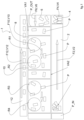
- reference number 1 designates as a whole a facility that carries out first embodiments of the method which is not according to the invention.
- the facility 1 comprises a first conveyor 2, a second conveyor 4 subsequent to the first conveyor, and a third conveyor 6 subsequent to the second conveyor 4.
- the second conveyor 4 has a conveyor direction F4 offset from a conveyor direction F2 of the first conveyor 2 (preferably directions F2 and F4 lie at a right angle)
- the third conveyor 6 has a conveyor direction F6 offset from the conveyor direction F4 of the second conveyor 4 (preferably directions F4 and F6 lie at a right angle, whereby direction F6 is parallel to direction F2 to define a U-shaped combined conveyor path).
- the second conveyor 4 has a conveyor speed V4 higher than a conveyor speed V2 of the first conveyor 2 and the third conveyor 6 has a conveyor speed V6 higher than the conveyor speed V4 of the second conveyor 4.
- a combination of conveyor speed and conveyor direction offset are combined at each conveyor transition.
- no conveyor height offsets are envisaged in the facility 1.
- the product input P_IN is located upstream of the conveyor 2 (reference is made to the conveyor direction F2) and the product output P_OUT is located downstream of the conveyor 6 (reference is made to the conveyor direction F6).
- the facility 1 may advantageously comprise a product sorting apparatus.
- the product sorting apparatus comprises a product sorting area 8 located downstream of the product output P_OUT and configured to receive the spaced products output by the conveyor 6.
- the sorting area 8 may advantageously itself be provided by a sorting conveyor 10 moving in a conveyor direction F10 that prosecutes the conveyor direction F6 (i.e. is aligned thereto), and preferably having no conveyor speed offset with respect to the conveyor 6.
- the function of the sorting conveyor 10 is essentialy that of transferring the products from the product output P_OUT to the product sorting area 8.
- One or more picking robots R1, R2, R3, R4 are provided at the sorting area, preferably in an overhead position. Overhead picking robots are per se known and will not be described in detail.
- the picking robots R1-R4 are assisted by means of at least one vision system positioned at the sorting conveyor 10 and operating at one or more vision areas VA1, VA2 along the sorting conveyor 10 in the direction F10).
- Each vision system is configured for identifying the products P at the sorting conveyor 10 and guiding the one or more picking robots R1-R4 to locations of the identified products.
- Each picking robot R1-R4 is so configured for picking products from the product sorting area 8 and releasing batches of picked products P onto a discharge conveyor 12, the batches of picked products being variable in size according to the size of the sale unit.
- the sorting conveyor 10 gives out to a recirculation chute or conveyor 14, which recirculates non-picked or non identified products P to the product input P_IN.
- the facility 1 When in operation, the facility 1 is supplied with a large initial batch of products P which are manually withdrawn from large handling containers by operators and dropped altogether at the product input P_IN.
- the number of products P in the initial batch is largely variable depending on the withdrawal by the operators, and randomly arranged.
- the products P When dropped at the product input P_IN, the products P immediately fall onto the first conveyor 2 and begin traveling towards the product output P_OUT in the conveyor direction F2.
- the combination of conveyor speed offset and conveyor direction offset F2 to F4 deconstructs the original arrangement of products P on the conveyor 2 to a new arrangement having a higher spread.
- the products P are sequentially separated based on the foregoing description regarding the conveyor speed offset (grip-and-acceleration sequence) and the conveyor direction (grip-and-deviation) offset.
- a second spread of the products P occurs at the conveyor transition between the second conveyor 4 and the third conveyor 6, with a new conveyor direction offset (F4 to F6) and a new conveyor speed offset.
- the products P are sequentially (further) separated based on the foregoing description regarding the conveyor speed offset (grip-and-acceleration sequence) and the conveyor direction (grip-and-deviation) offset. Accordingly, the products P are delivered to the product output P_OUT by the conveyor 6 as spread and spaced items, ready to enter the product sorting area 8.
- the initial arrangement of the products P at the product in put P_IN featured a random distribution of stacked, piled, and altogether densely packed products P: such an arrangement makes it impossible for the products P to be handled automatically, as robotic handling/picking devices (such as the picking robots R1-R4) would simply be unable to correctly locate a product to be picked due to the picking area being simply too crowded. In such circumstances, not even vision systems are capable of assisting the picking/handling devices to locate products due to the very arrangement thereof.
- the products P delivered to the product output P_OUT and on to the sorting area 8 are sufficiently spaced and spread to allow identification hereof by the vision system(s) and picking by the robots R1-R4, which are accordingly enabled to pick individual products P from the product sorting areas 8 (particularly from the sorting conveyor 10) and releasing batches of picked products P onto the discharge conveyor 12, wherein the batches of products assembled (released) onto the conveyor 12 are differently sized based on the size of the associated sale unit.
- Non-picked or non-identified products P are dimply recirculated to the product input P_IN by the recirculation chute or conveyor 14.
- the facility 1 can operate even without a conveyor speed offset between subsequent conveyors.
- the sole conveyor direction offset may be enough to achieve the desired product spreading and spacing.
- the addition of a conveyor speed offset increases the product spread, or - equivalently - allows the processing of larger initial batches of products P while meeting spread and spacing requirements.
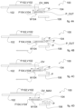
- reference number 100 designates as a whole a facility for carrying out a method according to the invention.
- the facility 100 is illustrated only as far as the conveyors implementing the method are concerned. Further co-operating devices or units are not shown, but it shall be understood that the provision of a product sorting area downstream of the product output P_OUT is of course possible.
- the plurality of subsequent conveyors comprises a first conveyor 102 and a second conveyor 106 subsequent to the first conveyor 102, wherein the second conveyor 104 has a conveyor height H104 that is lower than a conveyor height H102 of the first conveyor 102, and no conveyor direction offset with respect to the first conveyor 102. Accordingly, thereis a height offset O104 between the conveyor 104 and the conveyor 102. Heights H104 and H102 (as well as H106 for the conveyor 106) are measured from the ground or common reference G.
- the conveyors 102, 104 each have a conveyor direction F102, F104 aligned with one another.
- the product output P_OUT is located at the conveyor 106 downstream of the second conveyor 104 at a lower height H106 as compared to the height H104, so there is another height offset even at the product output P_OUT, which is provided as a transfer conveyor 106.
- Preferred embodiments feature a curved path transfer conveyor to accommodate a turn towards - for instance - a product sorting area without making the facility too long in the process direction.
- the conveyor 102 is operated at a conveyor speed V102
- the conveyor 104 is operated at a conveyor speed V104, which is variable according to the description that follows.
- the second conveyor 104 is also movable relative to the first conveyor 102 in the conveyor direction F104 (back and forth, speed W104) so as to provide a variation in an overlap OV between the first conveyor 102 and the second conveyor 104.
- the absolute speed of the products P moving over the conveyor 104 is a combination of speeds V104 and W104, of course subject to the orientation thereof, wherein V104 is the conveyor speed meant as the speed at which the mobile section(s) of the conveyor (e.g. a chain. A belt, etc.) move relative to the fixed section(s) thereof - hence the speed at which the products P move along through the conveyor 104, while W104 is a translational speed of the conveyor 104 as a whole, i.e.
- a product moving along the conveyor at a speed V104 relative to the fixed section(s) thereof may further be subject to a further speed component W104 owing to the translation of the conveyor as a whole with respect to an outer reference system, whereby the absolute speed of the products P on the conveyor 104 with respect to the outer reference system is a combination of speeds V104 and W104 (taking into account the orientation thereof, of course).
- the conveyor 104 is movable relative to the conveyor 102 from a condition of minimum overlap OV_MIN illustrated in figure 4A , and a condition of maximum overlap illustrated in figure 4D .
- the method according to the invention comprises:
- the latter step encourages the products P off the second conveyor 104 and onto the conveyor 106 and promotes a further spreading and spacing of the products P. It is a combination of a conveyor speed offset (the conveyor speed of the first conveyor 102 is constant, while the conveyor speed of the conveyor 104 is time-variable from zero to a predetermined conveyor speed and back when the conveyor 104 shuttles back to the minimum overlap position).
- the conveyor 104 is shuttled back to the condition of minimum overlap OV_MIN of figure 4A and the cycle restarts upon reception of a new scrambled flow of products P.
- a shuttling conveyor 104 allows construction of a more compact facility in the conveyor direction(s): as visible in figures 4A to 4D , the conveyor 106 can be arranged just downstream of the conveyor 102, as if it were to directly received by the conveyor 106.
- the conveyor 104 hovers above the conveyor 106 just as long as required to receive the products P from the conveyor 102, then starts moving away from the conveyor 106 and at the same time relays the products P to the conveyor 106 itself, which is gradually uncovered by the retraction motion of the conveyor 104 and made available for the products P to land onto.
- the products P that are delivered to the product output P_OUT are spread and spaced as compared to the initial arrangement at the product input. Similarly to the facility 1, this allows further processing of the products P at a product sorting area 8 identical - and identically operating - to that described in respect of the facility 1.
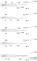
- the discharge conveyor 12 may be integrated in a discharge facility 200 ( figures 5-9 ) which is configured to process different formats of the product P while also facilitating relaying of the assembled product batches to a further processing facility or stage.
- the discharge facility 200 comprises the discharge conveyor 12 provided with a plurality of vanes or pins 202 configured for individually receiving products P released by the picking robots R1-R4 (or equivalent handling units). Both the conveyor 12 and the pins or vanes 202 are arranged between a pair of slide plates 204, 206, with the conveyor 102 essentially lying flush with the slide plates 204, 206 so that only the pins or vanes 202 stick out of the slide plates 204, 206.
- the conveyor 12 operates according to a conveyor direction F12 and a conveyor speed V12, while the slide plates 204, 206 are fixed in position.
- the slide plates 204, 206 extend over the end of the conveyor 12 to define a channel or track C200.
- the track or channel C200 may advantageously serve as a mating interface for a takeaway conveyor 300 having a conveyor direction F300 identical (prosecuting) the direction F12, and a conveyor speed V300 which is preferably identical to the speed V12.
- the takeaway conveyor 300 receives the products P at the end of the conveyor 12 and for the length of the channel or track C200 is still assisted by the slide plates 204, 206 as far as supporting products P1, P2 having different sizes. References P1, P2 are indistinctly applied in figure 9 essentially to convey that the relay to the take away conveyor 300 can be done regardless of the product size.
Landscapes
- Engineering & Computer Science (AREA)
- Mechanical Engineering (AREA)
- Attitude Control For Articles On Conveyors (AREA)
Claims (5)
- Verfahren zur Veränderung der räumlichen Anordnung von Produkten, umfassend:- Bereitstellen einer Vielzahl von nachfolgenden Förderern (2, 4, 6; 102, 104), die sich zwischen einem Produkteingang (P_IN) und einem Produktausgang (P_OUT) erstrecken,- Betreiben jedes Förderers (2, 4, 6; 102, 104) entsprechend einer jeweiligen Fördergeschwindigkeit (V2, V4, V6; V102, V104) und einer jeweiligen Förderrichtung (F2, F4, F6; F102, F104),- Eingeben einer Produkt-, (P), -charge in die Vielzahl nachfolgender Förderer (2, 4, 6; 102, 104), wobei die Produktcharge vom Produkteingang (P_IN) zum Produktausgang (P_OUT) gelangt und von jedem Förderer (2, 4, 102) der Vielzahl sequentiell an einen nachfolgenden Förderer der Vielzahl (4, 6; 104) weitergeleitet wird,wobei mindestens eine der Fördergeschwindigkeit (V2, V4, V6; V102, V104), der Förderrichtung (F2, F4, F6; F102, F104) und einer Förderhöhe (H102, H104) eines Förderers der Vielzahl jeweils von der Fördergeschwindigkeit (V2, V4, V6; V102, V104), der Förderrichtung (F2, F4, F6; F102, F104) und der Förderhöhe (H102, H104) des nachfolgenden Förderers in der Vielzahl versetzt ist,wobei die Vielzahl nachfolgender Förderer (102, 104) einen ersten Förderer (102) und einen zweiten Förderer (104) umfasst, der sich an den ersten Förderer (102) anschließt, wobei der zweite Förderer (104) eine geringere Förderhöhe (H104) als der erste Förderer (H102) und keinen Förderrichtungsversatz in Bezug auf den ersten Förderer (102) aufweist,wobei der zweite Förderer (104) relativ zum ersten Förderer (102) in der Förderrichtung (W104, F104) beweglich ist, um eine Variation einer Überlappung (OV, OV_MIN, OV_MAX) zwischen dem ersten Förderer (102) und dem zweiten Förderer (104) bereitzustellen, und wobei das Verfahren weiter umfasst:- Betreiben des ersten Förderers (102) mit einer ersten Fördergeschwindigkeit (V102), um Produkte (P) vom Produkteingang (P_IN) auf den zweiten Förderer (104) zu übertragen,- Positionieren des zweiten Förderers (104) bei einer minimalen Überlappung (OV_MIN) mit dem ersten Förderer (102) und Betreiben des zweiten Förderers (104) bei keiner Fördergeschwindigkeit,- Aufnehmen der Produkte (P) auf den zweiten Förderer (104),- Bewegen (W104) des zweiten Förderers (104) relativ zum ersten Förderer (102) vom Zustand minimaler Überlappung (OV_MIN) in einen Zustand maximaler Überlappung (OV_MAX),dadurch gekennzeichnet, dass das Verfahren weiter umfasst:- Betreiben des zweiten Förderers (104) mit einer Fördergeschwindigkeit (V104), wobei die Fördergeschwindigkeit (V104) des zweiten Förderers (104) höher ist als die Fördergeschwindigkeit (V102) des ersten Förderers (102), um die Produkte zum Produktausgang (P_OUT) zu übertragen, während der zweite Förderer (104) relativ zum ersten Förderer (102) vom Zustand minimaler Überlappung (OV_MIN) in einen Zustand maximaler Überlappung (OV_MAX) bewegt (W104) wird, undwobei der Produktausgang (P_OUT) eine geringere Förderhöhe (H106) aufweist als der zweite Förderer (104), und wobei der Produktausgang (P_OUT) durch einen Transferförderer (106) bereitgestellt wird.
- Verfahren nach Anspruch 1, wobei die Fördergeschwindigkeit (V2, V4; V102) jedes Förderers der Vielzahl von der Fördergeschwindigkeit des nachfolgenden Förderers in der Vielzahl (V4, V6; V104) versetzt ist.
- Verfahren nach Anspruch 2, wobei der Versatz der Fördergeschwindigkeit (V104) zeitlich variabel ist.
- Verfahren nach einem der vorstehenden Ansprüche, weiter umfassend:- Übertragen der Produkte (P) vom Produktausgang (P_OUT) zu einem Produktsortierbereich (8, 10)- Kommissionieren von Produkten (P) aus dem Produktsortierbereich (8, 10) und Freigeben von Chargen kommissionierter Produkte (P) auf einen Abladeförderer (12).
- Verfahren nach Anspruch 4, wobei der Produktsortierbereich (8) einen Sortierförderer (10) umfasst, und wobei das Kommissionieren von Produkten (P) aus dem Produktsortierbereich (8) umfasst:- Bereitstellen eines oder mehrerer Kommissionierroboter (R1, R2, R3, R4), vorzugsweise hängende Kommissionierroboter,- Unterstützen des einen oder der mehreren Kommissionierroboter (R1, R2, R3, R4) mittels mindestens eines Sichtsystems (VA1, VA2), das am Sortierförderer (10) positioniert ist, wobei das Sichtsystem zum Identifizieren der Produkte (P) im Produktsortierbereich (8) und zum Führen des einen oder der mehreren Kommissionierroboter (R1, R2, R3, R4) zu Standorten identifizierter Produkte (P) im Sortierbereich (8) konfiguriert ist, und- Rückführen nicht kommissionierter Produkte (P) zum Produkteingang (P_IN).
Priority Applications (2)
| Application Number | Priority Date | Filing Date | Title |
|---|---|---|---|
| EP21199932.1A EP4159650B1 (de) | 2021-09-29 | 2021-09-29 | Verfahren zur veränderung der räumlichen anordnung von produkten |
| US17/954,503 US12116216B2 (en) | 2021-09-29 | 2022-09-28 | Method for varying the spatial arrangement of products |
Applications Claiming Priority (1)
| Application Number | Priority Date | Filing Date | Title |
|---|---|---|---|
| EP21199932.1A EP4159650B1 (de) | 2021-09-29 | 2021-09-29 | Verfahren zur veränderung der räumlichen anordnung von produkten |
Publications (3)
| Publication Number | Publication Date |
|---|---|
| EP4159650A1 EP4159650A1 (de) | 2023-04-05 |
| EP4159650B1 true EP4159650B1 (de) | 2025-06-04 |
| EP4159650C0 EP4159650C0 (de) | 2025-06-04 |
Family
ID=78179194
Family Applications (1)
| Application Number | Title | Priority Date | Filing Date |
|---|---|---|---|
| EP21199932.1A Active EP4159650B1 (de) | 2021-09-29 | 2021-09-29 | Verfahren zur veränderung der räumlichen anordnung von produkten |
Country Status (2)
| Country | Link |
|---|---|
| US (1) | US12116216B2 (de) |
| EP (1) | EP4159650B1 (de) |
Family Cites Families (19)
| Publication number | Priority date | Publication date | Assignee | Title |
|---|---|---|---|---|
| US3259225A (en) * | 1960-02-16 | 1966-07-05 | Henry C Lehde | Marshalling apparatus |
| US3224553A (en) * | 1963-02-27 | 1965-12-21 | Milford A Campbell | Vibratory work feeding and orienting unit |
| DE2804585A1 (de) * | 1978-02-03 | 1979-08-09 | Schenck Ag Carl | Einrichtung zur vergleichmaessigung von schuettgut |
| FR2651756B1 (fr) * | 1989-09-13 | 1995-03-31 | Inst Tech Agricole Lin | Procede et dispositif de regularisation et de reglage de l'alimentation d'une unite de transformation industrielle. |
| BR9402010A (pt) * | 1993-06-25 | 1995-01-17 | Sig Schweiz Industrieges | Dispositivo para separar, transportar e agrupar objetos achatados |
| IT1301696B1 (it) * | 1998-06-12 | 2000-07-07 | Cml Handling Technology S P A | Metodo ed apparecchiatura per il caricamento automatico di piu'oggetti ordinati, sulla stessa unita' di una macchina smistatrice |
| DE29921672U1 (de) * | 1999-12-09 | 2001-04-19 | G.B. Boucherie N.V., Izegem | Vereinzelungssystem |
| US6755606B2 (en) * | 2001-09-17 | 2004-06-29 | Siemens Aktiengesellschaft | Jogging apparatus |
| FR2936787B1 (fr) * | 2008-10-03 | 2015-02-27 | Sidel Participations | Procede de preparation de lots de produits, bouteilles ou autres, et installation pour sa mise en oeuvre |
| EP2586712B2 (de) * | 2011-10-31 | 2018-02-14 | Veltru AG | Verfahren und Vorrichtung zum Einlegen von Produkten in Behälter in einer Roboterstrasse |
| US9630784B2 (en) * | 2015-05-15 | 2017-04-25 | Laitram, L.L.C. | Transfer-roller destacker |
| DE102016111110A1 (de) * | 2016-06-17 | 2017-12-21 | Deutsche Post Ag | Ansteuerung von Fördermitteln |
| US10061308B2 (en) * | 2016-09-16 | 2018-08-28 | Siemens Industry, Inc. | Parcel delayering systems and methods for automatic parcel processing based on accurate de-layering |
| US10315859B1 (en) * | 2017-03-20 | 2019-06-11 | Amazon Technologies, Inc. | Automatic singulation of items |
| US11186444B2 (en) * | 2017-10-27 | 2021-11-30 | Ronchi Mario S.P.A. | Apparatus for unscrambling randomly arranged containers |
| JP2019209276A (ja) * | 2018-06-06 | 2019-12-12 | 日本協同企画株式会社 | 廃材選別方法及び廃材選別装置 |
| US10961060B1 (en) * | 2018-12-13 | 2021-03-30 | Amazon Technologies, Inc. | Automated singulation system |
| MX2022010067A (es) * | 2020-02-24 | 2022-08-25 | Mat Handling Systems Inc | Sistema de manejo de flujo de paquetes con transportador de represamiento. |
| EP3971116A1 (de) * | 2020-09-17 | 2022-03-23 | Caljan A/S | Systeme, vorrichtungen und verfahren für erweiterbare förderer |
-
2021
- 2021-09-29 EP EP21199932.1A patent/EP4159650B1/de active Active
-
2022
- 2022-09-28 US US17/954,503 patent/US12116216B2/en active Active
Also Published As
| Publication number | Publication date |
|---|---|
| US20230108013A1 (en) | 2023-04-06 |
| US12116216B2 (en) | 2024-10-15 |
| EP4159650C0 (de) | 2025-06-04 |
| EP4159650A1 (de) | 2023-04-05 |
Similar Documents
| Publication | Publication Date | Title |
|---|---|---|
| US6688839B1 (en) | Device for processing bottles | |
| US9487315B2 (en) | Machine for packaging articles into cartons | |
| US8899001B2 (en) | Process and machine for outer packaging of articles | |
| US4991708A (en) | Apparatus for forming groups of articles, particularly for automatic packaging lines | |
| US20150158611A1 (en) | Variable pitch packaging apparatus and methods | |
| US20110243707A1 (en) | Method and equipment for dispensing products for packaging same | |
| US8464501B2 (en) | Method and installation for grouping of stackable products of the cases and other type | |
| EP3318498B1 (de) | Verfahren und vorrichtung zum verpacken von objektgruppen | |
| US20140123606A1 (en) | Method and Device To Insert Individual Products Into Containers In An Automated Line | |
| US11530060B2 (en) | Handling apparatus and/or packaging apparatus and method used to package article groups in outer packaging | |
| CN109071124B (zh) | 用于处理依次运动的成件货物的方法和设备 | |
| US5560184A (en) | Means for and methods of loading and packaging variable numbers of products | |
| US12116217B2 (en) | Apparatus and method for sequencing loading units in a predetermined order | |
| EP4051458B1 (de) | Modulare vorrichtung und verfahren zum befüllen und verschliessen von gegenständen, anlage mit einer modularen vorrichtung | |
| CN113260585A (zh) | 用于对容器进行分组的装置 | |
| US4546594A (en) | Machine and method for loading cartons with irregularly shaped individual articles | |
| US20180222612A1 (en) | Food conveyor and packaging systems and methods | |
| US20160075459A1 (en) | Method and device for handling elongated articles | |
| EP4159650B1 (de) | Verfahren zur veränderung der räumlichen anordnung von produkten | |
| CN217172184U (zh) | 用于对容器进行缓冲的缓冲设备 | |
| GB1587715A (en) | Article handling apparatus | |
| EP0552981A1 (de) | Verpackungssystem des Typs-4/12 | |
| EP4172044B1 (de) | Verpackungsmaschine zum horizontalen und vertikalen verpacken von gegenständen in eine verpackungsschachtel | |
| US6397563B1 (en) | Method and device for packaging flat products | |
| US6557693B1 (en) | Conveyor section arrangement for containers being filled with items or bulk material at a filling station |
Legal Events
| Date | Code | Title | Description |
|---|---|---|---|
| PUAI | Public reference made under article 153(3) epc to a published international application that has entered the european phase |
Free format text: ORIGINAL CODE: 0009012 |
|
| STAA | Information on the status of an ep patent application or granted ep patent |
Free format text: STATUS: THE APPLICATION HAS BEEN PUBLISHED |
|
| AK | Designated contracting states |
Kind code of ref document: A1 Designated state(s): AL AT BE BG CH CY CZ DE DK EE ES FI FR GB GR HR HU IE IS IT LI LT LU LV MC MK MT NL NO PL PT RO RS SE SI SK SM TR |
|
| STAA | Information on the status of an ep patent application or granted ep patent |
Free format text: STATUS: REQUEST FOR EXAMINATION WAS MADE |
|
| 17P | Request for examination filed |
Effective date: 20231003 |
|
| RBV | Designated contracting states (corrected) |
Designated state(s): AL AT BE BG CH CY CZ DE DK EE ES FI FR GB GR HR HU IE IS IT LI LT LU LV MC MK MT NL NO PL PT RO RS SE SI SK SM TR |
|
| STAA | Information on the status of an ep patent application or granted ep patent |
Free format text: STATUS: EXAMINATION IS IN PROGRESS |
|
| 17Q | First examination report despatched |
Effective date: 20240506 |
|
| GRAP | Despatch of communication of intention to grant a patent |
Free format text: ORIGINAL CODE: EPIDOSNIGR1 |
|
| STAA | Information on the status of an ep patent application or granted ep patent |
Free format text: STATUS: GRANT OF PATENT IS INTENDED |
|
| INTG | Intention to grant announced |
Effective date: 20250221 |
|
| GRAS | Grant fee paid |
Free format text: ORIGINAL CODE: EPIDOSNIGR3 |
|
| GRAA | (expected) grant |
Free format text: ORIGINAL CODE: 0009210 |
|
| STAA | Information on the status of an ep patent application or granted ep patent |
Free format text: STATUS: THE PATENT HAS BEEN GRANTED |
|
| AK | Designated contracting states |
Kind code of ref document: B1 Designated state(s): AL AT BE BG CH CY CZ DE DK EE ES FI FR GB GR HR HU IE IS IT LI LT LU LV MC MK MT NL NO PL PT RO RS SE SI SK SM TR |
|
| REG | Reference to a national code |
Ref country code: GB Ref legal event code: FG4D |
|
| REG | Reference to a national code |
Ref country code: CH Ref legal event code: EP |
|
| REG | Reference to a national code |
Ref country code: DE Ref legal event code: R096 Ref document number: 602021031667 Country of ref document: DE |
|
| REG | Reference to a national code |
Ref country code: IE Ref legal event code: FG4D |
|
| U01 | Request for unitary effect filed |
Effective date: 20250702 |
|
| U07 | Unitary effect registered |
Designated state(s): AT BE BG DE DK EE FI FR IT LT LU LV MT NL PT RO SE SI Effective date: 20250708 |
|
| PG25 | Lapsed in a contracting state [announced via postgrant information from national office to epo] |
Ref country code: ES Free format text: LAPSE BECAUSE OF FAILURE TO SUBMIT A TRANSLATION OF THE DESCRIPTION OR TO PAY THE FEE WITHIN THE PRESCRIBED TIME-LIMIT Effective date: 20250604 |
|
| PG25 | Lapsed in a contracting state [announced via postgrant information from national office to epo] |
Ref country code: NO Free format text: LAPSE BECAUSE OF FAILURE TO SUBMIT A TRANSLATION OF THE DESCRIPTION OR TO PAY THE FEE WITHIN THE PRESCRIBED TIME-LIMIT Effective date: 20250904 Ref country code: GR Free format text: LAPSE BECAUSE OF FAILURE TO SUBMIT A TRANSLATION OF THE DESCRIPTION OR TO PAY THE FEE WITHIN THE PRESCRIBED TIME-LIMIT Effective date: 20250905 |
|
| PG25 | Lapsed in a contracting state [announced via postgrant information from national office to epo] |
Ref country code: PL Free format text: LAPSE BECAUSE OF FAILURE TO SUBMIT A TRANSLATION OF THE DESCRIPTION OR TO PAY THE FEE WITHIN THE PRESCRIBED TIME-LIMIT Effective date: 20250604 |
|
| PG25 | Lapsed in a contracting state [announced via postgrant information from national office to epo] |
Ref country code: HR Free format text: LAPSE BECAUSE OF FAILURE TO SUBMIT A TRANSLATION OF THE DESCRIPTION OR TO PAY THE FEE WITHIN THE PRESCRIBED TIME-LIMIT Effective date: 20250604 |
|
| PG25 | Lapsed in a contracting state [announced via postgrant information from national office to epo] |
Ref country code: RS Free format text: LAPSE BECAUSE OF FAILURE TO SUBMIT A TRANSLATION OF THE DESCRIPTION OR TO PAY THE FEE WITHIN THE PRESCRIBED TIME-LIMIT Effective date: 20250904 |
|
| U20 | Renewal fee for the european patent with unitary effect paid |
Year of fee payment: 5 Effective date: 20250929 |