EP4159564A1 - Procédé et dispositif de planification de paramètres de mouvement longitudinal de véhicule - Google Patents
Procédé et dispositif de planification de paramètres de mouvement longitudinal de véhicule Download PDFInfo
- Publication number
- EP4159564A1 EP4159564A1 EP21824973.8A EP21824973A EP4159564A1 EP 4159564 A1 EP4159564 A1 EP 4159564A1 EP 21824973 A EP21824973 A EP 21824973A EP 4159564 A1 EP4159564 A1 EP 4159564A1
- Authority
- EP
- European Patent Office
- Prior art keywords
- vehicle
- obstacle
- time
- occupy
- temporal
- Prior art date
- Legal status (The legal status is an assumption and is not a legal conclusion. Google has not performed a legal analysis and makes no representation as to the accuracy of the status listed.)
- Pending
Links
- 238000000034 method Methods 0.000 title claims abstract description 80
- 230000007774 longterm Effects 0.000 claims description 84
- 230000015654 memory Effects 0.000 claims description 38
- 238000012545 processing Methods 0.000 claims description 26
- 230000008859 change Effects 0.000 claims description 18
- 238000001514 detection method Methods 0.000 claims description 10
- 238000004590 computer program Methods 0.000 claims description 7
- 238000004364 calculation method Methods 0.000 abstract description 21
- 238000004891 communication Methods 0.000 description 27
- 230000008569 process Effects 0.000 description 24
- 230000006870 function Effects 0.000 description 23
- 230000001133 acceleration Effects 0.000 description 16
- 230000006399 behavior Effects 0.000 description 15
- 238000010586 diagram Methods 0.000 description 14
- 238000005516 engineering process Methods 0.000 description 9
- 230000002093 peripheral effect Effects 0.000 description 8
- 230000000717 retained effect Effects 0.000 description 8
- 238000012795 verification Methods 0.000 description 7
- 238000013473 artificial intelligence Methods 0.000 description 6
- 241001465754 Metazoa Species 0.000 description 5
- 238000006073 displacement reaction Methods 0.000 description 5
- 230000005540 biological transmission Effects 0.000 description 4
- 230000003993 interaction Effects 0.000 description 4
- 230000009471 action Effects 0.000 description 3
- 238000004422 calculation algorithm Methods 0.000 description 3
- 230000008878 coupling Effects 0.000 description 3
- 238000010168 coupling process Methods 0.000 description 3
- 238000005859 coupling reaction Methods 0.000 description 3
- 239000000446 fuel Substances 0.000 description 3
- 238000007726 management method Methods 0.000 description 3
- ATUOYWHBWRKTHZ-UHFFFAOYSA-N Propane Chemical compound CCC ATUOYWHBWRKTHZ-UHFFFAOYSA-N 0.000 description 2
- 238000013528 artificial neural network Methods 0.000 description 2
- 238000002485 combustion reaction Methods 0.000 description 2
- 230000006835 compression Effects 0.000 description 2
- 238000007906 compression Methods 0.000 description 2
- 230000008094 contradictory effect Effects 0.000 description 2
- 238000013461 design Methods 0.000 description 2
- 238000005259 measurement Methods 0.000 description 2
- 238000010295 mobile communication Methods 0.000 description 2
- 230000003068 static effect Effects 0.000 description 2
- LFQSCWFLJHTTHZ-UHFFFAOYSA-N Ethanol Chemical compound CCO LFQSCWFLJHTTHZ-UHFFFAOYSA-N 0.000 description 1
- 101001093748 Homo sapiens Phosphatidylinositol N-acetylglucosaminyltransferase subunit P Proteins 0.000 description 1
- HBBGRARXTFLTSG-UHFFFAOYSA-N Lithium ion Chemical compound [Li+] HBBGRARXTFLTSG-UHFFFAOYSA-N 0.000 description 1
- 206010039203 Road traffic accident Diseases 0.000 description 1
- 239000002253 acid Substances 0.000 description 1
- 230000010267 cellular communication Effects 0.000 description 1
- 230000001413 cellular effect Effects 0.000 description 1
- 238000010276 construction Methods 0.000 description 1
- 238000000354 decomposition reaction Methods 0.000 description 1
- 229910001416 lithium ion Inorganic materials 0.000 description 1
- 238000013507 mapping Methods 0.000 description 1
- 238000012544 monitoring process Methods 0.000 description 1
- 238000003058 natural language processing Methods 0.000 description 1
- 230000003287 optical effect Effects 0.000 description 1
- 238000005457 optimization Methods 0.000 description 1
- 230000008447 perception Effects 0.000 description 1
- 239000003208 petroleum Substances 0.000 description 1
- 239000001294 propane Substances 0.000 description 1
- 238000000926 separation method Methods 0.000 description 1
- 239000000126 substance Substances 0.000 description 1
Images


Classifications
-
- B—PERFORMING OPERATIONS; TRANSPORTING
- B60—VEHICLES IN GENERAL
- B60W—CONJOINT CONTROL OF VEHICLE SUB-UNITS OF DIFFERENT TYPE OR DIFFERENT FUNCTION; CONTROL SYSTEMS SPECIALLY ADAPTED FOR HYBRID VEHICLES; ROAD VEHICLE DRIVE CONTROL SYSTEMS FOR PURPOSES NOT RELATED TO THE CONTROL OF A PARTICULAR SUB-UNIT
- B60W60/00—Drive control systems specially adapted for autonomous road vehicles
- B60W60/001—Planning or execution of driving tasks
-
- B—PERFORMING OPERATIONS; TRANSPORTING
- B60—VEHICLES IN GENERAL
- B60W—CONJOINT CONTROL OF VEHICLE SUB-UNITS OF DIFFERENT TYPE OR DIFFERENT FUNCTION; CONTROL SYSTEMS SPECIALLY ADAPTED FOR HYBRID VEHICLES; ROAD VEHICLE DRIVE CONTROL SYSTEMS FOR PURPOSES NOT RELATED TO THE CONTROL OF A PARTICULAR SUB-UNIT
- B60W30/00—Purposes of road vehicle drive control systems not related to the control of a particular sub-unit, e.g. of systems using conjoint control of vehicle sub-units
- B60W30/08—Active safety systems predicting or avoiding probable or impending collision or attempting to minimise its consequences
- B60W30/09—Taking automatic action to avoid collision, e.g. braking and steering
-
- B—PERFORMING OPERATIONS; TRANSPORTING
- B60—VEHICLES IN GENERAL
- B60W—CONJOINT CONTROL OF VEHICLE SUB-UNITS OF DIFFERENT TYPE OR DIFFERENT FUNCTION; CONTROL SYSTEMS SPECIALLY ADAPTED FOR HYBRID VEHICLES; ROAD VEHICLE DRIVE CONTROL SYSTEMS FOR PURPOSES NOT RELATED TO THE CONTROL OF A PARTICULAR SUB-UNIT
- B60W30/00—Purposes of road vehicle drive control systems not related to the control of a particular sub-unit, e.g. of systems using conjoint control of vehicle sub-units
- B60W30/08—Active safety systems predicting or avoiding probable or impending collision or attempting to minimise its consequences
- B60W30/095—Predicting travel path or likelihood of collision
- B60W30/0956—Predicting travel path or likelihood of collision the prediction being responsive to traffic or environmental parameters
-
- B—PERFORMING OPERATIONS; TRANSPORTING
- B60—VEHICLES IN GENERAL
- B60W—CONJOINT CONTROL OF VEHICLE SUB-UNITS OF DIFFERENT TYPE OR DIFFERENT FUNCTION; CONTROL SYSTEMS SPECIALLY ADAPTED FOR HYBRID VEHICLES; ROAD VEHICLE DRIVE CONTROL SYSTEMS FOR PURPOSES NOT RELATED TO THE CONTROL OF A PARTICULAR SUB-UNIT
- B60W30/00—Purposes of road vehicle drive control systems not related to the control of a particular sub-unit, e.g. of systems using conjoint control of vehicle sub-units
- B60W30/14—Adaptive cruise control
- B60W30/143—Speed control
-
- B—PERFORMING OPERATIONS; TRANSPORTING
- B60—VEHICLES IN GENERAL
- B60W—CONJOINT CONTROL OF VEHICLE SUB-UNITS OF DIFFERENT TYPE OR DIFFERENT FUNCTION; CONTROL SYSTEMS SPECIALLY ADAPTED FOR HYBRID VEHICLES; ROAD VEHICLE DRIVE CONTROL SYSTEMS FOR PURPOSES NOT RELATED TO THE CONTROL OF A PARTICULAR SUB-UNIT
- B60W60/00—Drive control systems specially adapted for autonomous road vehicles
- B60W60/001—Planning or execution of driving tasks
- B60W60/0011—Planning or execution of driving tasks involving control alternatives for a single driving scenario, e.g. planning several paths to avoid obstacles
-
- B—PERFORMING OPERATIONS; TRANSPORTING
- B60—VEHICLES IN GENERAL
- B60W—CONJOINT CONTROL OF VEHICLE SUB-UNITS OF DIFFERENT TYPE OR DIFFERENT FUNCTION; CONTROL SYSTEMS SPECIALLY ADAPTED FOR HYBRID VEHICLES; ROAD VEHICLE DRIVE CONTROL SYSTEMS FOR PURPOSES NOT RELATED TO THE CONTROL OF A PARTICULAR SUB-UNIT
- B60W60/00—Drive control systems specially adapted for autonomous road vehicles
- B60W60/001—Planning or execution of driving tasks
- B60W60/0027—Planning or execution of driving tasks using trajectory prediction for other traffic participants
- B60W60/00272—Planning or execution of driving tasks using trajectory prediction for other traffic participants relying on extrapolation of current movement
-
- B—PERFORMING OPERATIONS; TRANSPORTING
- B60—VEHICLES IN GENERAL
- B60W—CONJOINT CONTROL OF VEHICLE SUB-UNITS OF DIFFERENT TYPE OR DIFFERENT FUNCTION; CONTROL SYSTEMS SPECIALLY ADAPTED FOR HYBRID VEHICLES; ROAD VEHICLE DRIVE CONTROL SYSTEMS FOR PURPOSES NOT RELATED TO THE CONTROL OF A PARTICULAR SUB-UNIT
- B60W60/00—Drive control systems specially adapted for autonomous road vehicles
- B60W60/001—Planning or execution of driving tasks
- B60W60/0027—Planning or execution of driving tasks using trajectory prediction for other traffic participants
- B60W60/00276—Planning or execution of driving tasks using trajectory prediction for other traffic participants for two or more other traffic participants
-
- B—PERFORMING OPERATIONS; TRANSPORTING
- B60—VEHICLES IN GENERAL
- B60K—ARRANGEMENT OR MOUNTING OF PROPULSION UNITS OR OF TRANSMISSIONS IN VEHICLES; ARRANGEMENT OR MOUNTING OF PLURAL DIVERSE PRIME-MOVERS IN VEHICLES; AUXILIARY DRIVES FOR VEHICLES; INSTRUMENTATION OR DASHBOARDS FOR VEHICLES; ARRANGEMENTS IN CONNECTION WITH COOLING, AIR INTAKE, GAS EXHAUST OR FUEL SUPPLY OF PROPULSION UNITS IN VEHICLES
- B60K31/00—Vehicle fittings, acting on a single sub-unit only, for automatically controlling vehicle speed, i.e. preventing speed from exceeding an arbitrarily established velocity or maintaining speed at a particular velocity, as selected by the vehicle operator
- B60K31/0008—Vehicle fittings, acting on a single sub-unit only, for automatically controlling vehicle speed, i.e. preventing speed from exceeding an arbitrarily established velocity or maintaining speed at a particular velocity, as selected by the vehicle operator including means for detecting potential obstacles in vehicle path
- B60K2031/0016—Identification of obstacles; Selection of a target vehicle
-
- B—PERFORMING OPERATIONS; TRANSPORTING
- B60—VEHICLES IN GENERAL
- B60K—ARRANGEMENT OR MOUNTING OF PROPULSION UNITS OR OF TRANSMISSIONS IN VEHICLES; ARRANGEMENT OR MOUNTING OF PLURAL DIVERSE PRIME-MOVERS IN VEHICLES; AUXILIARY DRIVES FOR VEHICLES; INSTRUMENTATION OR DASHBOARDS FOR VEHICLES; ARRANGEMENTS IN CONNECTION WITH COOLING, AIR INTAKE, GAS EXHAUST OR FUEL SUPPLY OF PROPULSION UNITS IN VEHICLES
- B60K31/00—Vehicle fittings, acting on a single sub-unit only, for automatically controlling vehicle speed, i.e. preventing speed from exceeding an arbitrarily established velocity or maintaining speed at a particular velocity, as selected by the vehicle operator
- B60K31/0008—Vehicle fittings, acting on a single sub-unit only, for automatically controlling vehicle speed, i.e. preventing speed from exceeding an arbitrarily established velocity or maintaining speed at a particular velocity, as selected by the vehicle operator including means for detecting potential obstacles in vehicle path
- B60K2031/005—Selecting more than one target vehicle, e.g. using several preceding vehicles as target
-
- B—PERFORMING OPERATIONS; TRANSPORTING
- B60—VEHICLES IN GENERAL
- B60W—CONJOINT CONTROL OF VEHICLE SUB-UNITS OF DIFFERENT TYPE OR DIFFERENT FUNCTION; CONTROL SYSTEMS SPECIALLY ADAPTED FOR HYBRID VEHICLES; ROAD VEHICLE DRIVE CONTROL SYSTEMS FOR PURPOSES NOT RELATED TO THE CONTROL OF A PARTICULAR SUB-UNIT
- B60W2552/00—Input parameters relating to infrastructure
- B60W2552/50—Barriers
-
- B—PERFORMING OPERATIONS; TRANSPORTING
- B60—VEHICLES IN GENERAL
- B60W—CONJOINT CONTROL OF VEHICLE SUB-UNITS OF DIFFERENT TYPE OR DIFFERENT FUNCTION; CONTROL SYSTEMS SPECIALLY ADAPTED FOR HYBRID VEHICLES; ROAD VEHICLE DRIVE CONTROL SYSTEMS FOR PURPOSES NOT RELATED TO THE CONTROL OF A PARTICULAR SUB-UNIT
- B60W2554/00—Input parameters relating to objects
- B60W2554/40—Dynamic objects, e.g. animals, windblown objects
- B60W2554/404—Characteristics
- B60W2554/4041—Position
-
- B—PERFORMING OPERATIONS; TRANSPORTING
- B60—VEHICLES IN GENERAL
- B60W—CONJOINT CONTROL OF VEHICLE SUB-UNITS OF DIFFERENT TYPE OR DIFFERENT FUNCTION; CONTROL SYSTEMS SPECIALLY ADAPTED FOR HYBRID VEHICLES; ROAD VEHICLE DRIVE CONTROL SYSTEMS FOR PURPOSES NOT RELATED TO THE CONTROL OF A PARTICULAR SUB-UNIT
- B60W2554/00—Input parameters relating to objects
- B60W2554/40—Dynamic objects, e.g. animals, windblown objects
- B60W2554/404—Characteristics
- B60W2554/4042—Longitudinal speed
-
- B—PERFORMING OPERATIONS; TRANSPORTING
- B60—VEHICLES IN GENERAL
- B60W—CONJOINT CONTROL OF VEHICLE SUB-UNITS OF DIFFERENT TYPE OR DIFFERENT FUNCTION; CONTROL SYSTEMS SPECIALLY ADAPTED FOR HYBRID VEHICLES; ROAD VEHICLE DRIVE CONTROL SYSTEMS FOR PURPOSES NOT RELATED TO THE CONTROL OF A PARTICULAR SUB-UNIT
- B60W2554/00—Input parameters relating to objects
- B60W2554/40—Dynamic objects, e.g. animals, windblown objects
- B60W2554/404—Characteristics
- B60W2554/4045—Intention, e.g. lane change or imminent movement
-
- B—PERFORMING OPERATIONS; TRANSPORTING
- B60—VEHICLES IN GENERAL
- B60W—CONJOINT CONTROL OF VEHICLE SUB-UNITS OF DIFFERENT TYPE OR DIFFERENT FUNCTION; CONTROL SYSTEMS SPECIALLY ADAPTED FOR HYBRID VEHICLES; ROAD VEHICLE DRIVE CONTROL SYSTEMS FOR PURPOSES NOT RELATED TO THE CONTROL OF A PARTICULAR SUB-UNIT
- B60W2554/00—Input parameters relating to objects
- B60W2554/80—Spatial relation or speed relative to objects
- B60W2554/801—Lateral distance
-
- B—PERFORMING OPERATIONS; TRANSPORTING
- B60—VEHICLES IN GENERAL
- B60W—CONJOINT CONTROL OF VEHICLE SUB-UNITS OF DIFFERENT TYPE OR DIFFERENT FUNCTION; CONTROL SYSTEMS SPECIALLY ADAPTED FOR HYBRID VEHICLES; ROAD VEHICLE DRIVE CONTROL SYSTEMS FOR PURPOSES NOT RELATED TO THE CONTROL OF A PARTICULAR SUB-UNIT
- B60W2554/00—Input parameters relating to objects
- B60W2554/80—Spatial relation or speed relative to objects
- B60W2554/802—Longitudinal distance
Definitions
- This application relates to the automated driving field, and more specifically, to a method and an apparatus for planning a longitudinal motion parameter of a vehicle.
- Artificial intelligence is a theory, a method, a technology, and an application system for using a digital computer or a machine controlled by a digital computer to simulate, extend, and expand human intelligence, sense an environment, obtain knowledge, and use the knowledge to obtain an optimal result.
- artificial intelligence is a branch of computer science and attempts to understand essence of intelligence and produce a new intelligent machine capable of reacting in a manner similar to that of human intelligence.
- Artificial intelligence is to study design principles and implementation methods of various intelligent machines to make the machines have perception, inference, and decision-making functions.
- Studies in the artificial intelligence field include robots, natural language processing, computer vision, decision-making and inference, human-computer interaction, recommendations and searches, basic theories of AI, and the like.
- Automated driving is a mainstream application in the artificial intelligence field.
- An automated driving technology relies on collaboration of computer vision, a radar, a monitoring apparatus, a global positioning system, and the like, to enable a motor vehicle to implement automated driving without a proactive operation of a human.
- An automated driving vehicle uses various computing systems to help transport a passenger from one position to another position. Some automated driving vehicles may require some initial inputs or continuous inputs from an operator (for example, a pilot, a driver, or a passenger).
- the automated driving vehicle allows the operator to switch from a manual operation mode to an automated driving mode or a mode between the manual operation mode and the automated driving mode.
- a path planning and decision-making function is one of the most basic and critical functions.
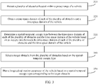
- the path planning and decision-making function is intended to adjust a travel policy of a vehicle in a timely and safe manner based on a dynamic change trend of an obstacle around the vehicle in a complex traffic environment. Performing proper planning and decision-making on a longitudinal motion parameter based on a result of predicting an obstacle around a vehicle is a key and difficult issue in a direction of an automated driving technology.
- a controller first obtains a current state of an automated driving vehicle at a current moment and spatial-temporal prediction data of all obstacles within a preset range. For each of all the obstacles, the controller determines a conflict time and space between each obstacle and the automated driving vehicle, and determines a planned travel trajectory of the automated driving vehicle based on the conflict time and space of each obstacle. Then the controller determines a target longitudinal motion parameter from a planned travel trajectory corresponding to each target object, and sends a control instruction to a control device of the automated vehicle based on the determined target longitudinal motion parameter.
- the controller needs to determine a standard longitudinal motion parameter of the automated driving vehicle based on the spatial-temporal prediction data of all the obstacles within the preset range, in other words, the controller needs to traverse the spatial-temporal prediction data of all the obstacles within the preset range, and calculate a target longitudinal motion parameter of the automated driving vehicle for each obstacle.
- a very large amount of calculation is required for calculating the longitudinal motion parameter.
- This application provides a method and an apparatus for planning a longitudinal motion parameter of a vehicle, to reduce an amount of calculation required for calculating a longitudinal motion parameter of a vehicle.
- a method for planning a longitudinal motion parameter of a vehicle including: detecting a plurality of obstacles located within a preset range of the vehicle; obtaining a time-space domain of each of the plurality of obstacles and a time-space domain of the vehicle, where the time-space domain of each obstacle is used to indicate a change of a position space of each obstacle with time, and the time-space domain of the vehicle is used to indicate a change of a position space occupied by the vehicle with time; determining a spatial-temporal occupy type between the time-space domain of each of the plurality of obstacles and the time-space domain of the vehicle based on an occupy time between the time-space domain of each of the plurality of obstacles and the time-space domain of the vehicle, where the occupy time is used to indicate a time period in which the position space of each of the plurality of obstacles occupies at least a part of a position of the vehicle; selecting a target obstacle from the plurality of obstacles based on the spatial-temporal occupy
- the spatial-temporal occupy type between the obstacle and the vehicle is determined; the target obstacle is selected from the plurality of obstacles based on the spatial-temporal occupy type; and the longitudinal motion parameter of the vehicle is planned based on the spatial-temporal occupy type corresponding to the target obstacle, thereby avoiding planning a longitudinal motion parameter of a vehicle based on each of a plurality of obstacles in a conventional technology, and helping reduce an amount of calculation required for planning the longitudinal parameter of the vehicle.
- a longitudinal direction may be understood as a direction that is the same as an axial direction of the vehicle. Therefore, the longitudinal motion parameter may be understood as a motion parameter in the axial direction of the vehicle.
- the spatial-temporal occupy type between the time-space domain of each of the plurality of obstacles and the time-space domain of the vehicle is a current long-term occupy type; if the time period corresponding to the occupy time is less than a second time period threshold, the spatial-temporal occupy type between the time-space domain of each of the plurality of obstacles and the time-space domain of the vehicle is a temporary occupy type; or if the occupy time is a period of time later than the collection moment, and the time period corresponding to the occupy time is greater than a third time period threshold, the spatial-temporal occupy type between the time-space domain of each of the plurality of obstacles and the time-space domain of the vehicle is a future long-term occupy type, where
- spatial-temporal occupy types are classified into the current long-term occupy type, the temporary occupy type, and the future long-term occupy type based on occupy times between time-space domains of obstacles and the time-space domain of the vehicle, so that the longitudinal motion parameter of the vehicle can be planned based on a time-space domain of an obstacle corresponding to each occupy type. This helps improve appropriateness of planning of the longitudinal motion parameter of the vehicle.
- a distance between the target obstacle and the vehicle is shorter than a distance between another obstacle and the vehicle, where the another obstacle is an obstacle other than the target obstacle in the plurality of obstacles; or a time to collision TTC between the target obstacle and the vehicle is shorter than a TTC between the another obstacle and the vehicle.
- an obstacle with a shortest distance from the vehicle or an obstacle with a shortest time to collision in the plurality of obstacles is used as a target obstacle corresponding to the temporary occupy type, to select an obstacle that has large impact on the longitudinal motion parameter of the vehicle from the temporary occupy type. This helps improve safety of planning of the longitudinal motion parameter of the vehicle.
- a longitudinal distance between the target obstacle and the vehicle is less than a longitudinal distance between another obstacle in the plurality of obstacles and the vehicle.
- the longitudinal direction may be understood as a direction that is the same as the axial direction of the vehicle. Therefore, the longitudinal distance may be understood as a distance between the obstacle and the vehicle in the axial direction of the vehicle.
- an obstacle with a shortest longitudinal distance from the vehicle in the plurality of obstacles is used as a target obstacle corresponding to the current long-term occupy type, to select an obstacle that has large impact on the longitudinal motion parameter of the vehicle from the current long-term occupy type. This helps improve safety of planning of the longitudinal motion parameter of the vehicle.
- a time to line TTL between the target obstacle and a lane in which the vehicle travels is shorter than a TTL between another obstacle and the lane, where the another obstacle is an obstacle other than the target obstacle in the plurality of obstacles.
- an obstacle with a shortest TTL from the lane in which the vehicle travels in the plurality of obstacles is used as a target obstacle corresponding to the future long-term occupy type, to select an obstacle that has large impact on the longitudinal motion parameter of the vehicle from the future long-term occupy type. This helps improve safety of planning of the longitudinal motion parameter of the vehicle.
- the planning a longitudinal motion parameter of the vehicle based on a spatial-temporal occupy type corresponding to the target obstacle includes: determining, based on the spatial-temporal occupy type corresponding to the target obstacle, a first constraint condition corresponding to the spatial-temporal occupy type of the target obstacle, where the first constraint condition is used to constrain the longitudinal motion parameter of the vehicle, to avoid collision between the target obstacle and the vehicle; obtaining a second constraint condition corresponding to another spatial-temporal occupy type, where the another spatial-temporal occupy type is a spatial-temporal occupy type other than the spatial-temporal occupy type in a plurality of spatial-temporal occupy types, and the second constraint condition is used to constrain the longitudinal motion parameter of the vehicle, to avoid collision between the vehicle and an obstacle corresponding to the another spatial-temporal occupy type; and planning the longitudinal motion parameter of the vehicle based on the first constraint condition and the second constraint condition.
- the first constraint corresponding to the spatial-temporal occupy type of the target obstacle and the second constraint corresponding to the another spatial-temporal occupy type are jointly used as a constraint condition for calculating the longitudinal motion parameter of the vehicle. This helps improve safety of planning of the longitudinal motion parameter of the vehicle.
- an apparatus for planning a longitudinal motion parameter of a vehicle including: a detection unit, configured to detect a plurality of obstacles located within a preset range of the vehicle; an obtaining unit, configured to obtain a time-space domain of each of the plurality of obstacles and a time-space domain of the vehicle, where the time-space domain of each obstacle is used to indicate a change of a position space of each obstacle with time, and the time-space domain of the vehicle is used to indicate a change of a position space occupied by the vehicle with time; and a processing unit, configured to determine a spatial-temporal occupy type between the time-space domain of each of the plurality of obstacles and the time-space domain of the vehicle based on an occupy time between the time-space domain of each of the plurality of obstacles and the time-space domain of the vehicle, where the occupy time is used to indicate a time period in which the position space of each of the plurality of obstacles occupies at least a part of a position of the vehicle, the processing unit
- the spatial-temporal occupy type between the obstacle and the vehicle is determined; the target obstacle is selected from the plurality of obstacles based on the spatial-temporal occupy type; and the longitudinal motion parameter of the vehicle is planned based on the spatial-temporal occupy type corresponding to the target obstacle, thereby avoiding planning a longitudinal motion parameter of a vehicle based on each of a plurality of obstacles in a conventional technology, and helping reduce an amount of calculation required for planning the longitudinal parameter of the vehicle.
- the spatial-temporal occupy type between the time-space domain of each of the plurality of obstacles and the time-space domain of the vehicle is a current long-term occupy type; if the time period corresponding to the occupy time is less than a second time period threshold, the spatial-temporal occupy type between the time-space domain of each of the plurality of obstacles and the time-space domain of the vehicle is a temporary occupy type; or if the occupy time is a period of time later than the collection moment, and the time period corresponding to the occupy time is greater than a third time period threshold, the spatial-temporal occupy type between the time-space domain of each of the plurality of obstacles and the time-space domain of the vehicle is a future long-term occupy type, where
- spatial-temporal occupy types are classified into the current long-term occupy type, the temporary occupy type, and the future long-term occupy type based on occupy times between time-space domains of obstacles and the time-space domain of the vehicle, so that the longitudinal motion parameter of the vehicle can be planned based on a time-space domain of an obstacle corresponding to each occupy type. This helps improve appropriateness of planning of the longitudinal motion parameter of the vehicle.
- a distance between the target obstacle and the vehicle is shorter than a distance between another obstacle and the vehicle, where the another obstacle is an obstacle other than the target obstacle in the plurality of obstacles; or a time to collision TTC between the target obstacle and the vehicle is shorter than a TTC between the another obstacle and the vehicle.
- an obstacle with a shortest distance from the vehicle or an obstacle with a shortest time to collision in the plurality of obstacles is used as a target obstacle corresponding to the temporary occupy type, to select an obstacle that has large impact on the longitudinal motion parameter of the vehicle from the temporary occupy type. This helps improve safety of planning of the longitudinal motion parameter of the vehicle.
- a longitudinal distance between the target obstacle and the vehicle is less than a longitudinal distance between another obstacle in the plurality of obstacles and the vehicle.
- an obstacle with a shortest longitudinal distance from the vehicle in the plurality of obstacles is used as a target obstacle corresponding to the current long-term occupy type, to select an obstacle that has large impact on the longitudinal motion parameter of the vehicle from the current long-term occupy type. This helps improve safety of planning of the longitudinal motion parameter of the vehicle.
- a time to line TTL between the target obstacle and a lane in which the vehicle travels is shorter than a TTL between another obstacle and the lane, where the another obstacle is an obstacle other than the target obstacle in the plurality of obstacles.
- an obstacle with a shortest TTL from the lane in which the vehicle travels in the plurality of obstacles is used as a target obstacle corresponding to the future long-term occupy type, to select an obstacle that has large impact on the longitudinal motion parameter of the vehicle from the future long-term occupy type. This helps improve safety of planning of the longitudinal motion parameter of the vehicle.
- the processing unit is further configured to: determine, based on the spatial-temporal occupy type corresponding to the target obstacle, a first constraint condition corresponding to the spatial-temporal occupy type of the target obstacle, where the first constraint condition is used to constrain the longitudinal motion parameter of the vehicle, to avoid collision between the target obstacle and the vehicle; obtain a second constraint condition corresponding to another spatial-temporal occupy type, where the another spatial-temporal occupy type is a spatial-temporal occupy type other than the spatial-temporal occupy type in a plurality of spatial-temporal occupy types, and the second constraint condition is used to constrain the longitudinal motion parameter of the vehicle, to avoid collision between the vehicle and an obstacle corresponding to the another spatial-temporal occupy type; and plan the longitudinal motion parameter of the vehicle based on the first constraint condition and the second constraint condition.
- the first constraint corresponding to the spatial-temporal occupy type of the target obstacle and the second constraint corresponding to the another spatial-temporal occupy type are jointly used as a constraint condition for calculating the longitudinal motion parameter of the vehicle. This helps improve safety of planning of the longitudinal motion parameter of the vehicle.
- a controller may be various devices with a control function, or may be a chip with a control function.
- the controller may include a detection unit, a processing unit, and an obtaining unit.
- the processing unit may be a processor, and the detection unit and the obtaining unit may be an input/output interface.
- the controller may further include a storage unit.
- the storage unit may be a memory, and the storage unit is configured to store instructions.
- the processing unit executes the instructions stored in the storage unit, so that the controller performs the method in the first aspect.
- the storage unit may be a storage unit (for example, a register or a cache) in the chip, or may be a storage unit (for example, a read-only memory or a random access memory) that is in the controller and that is located outside the chip.
- a computing device may be various devices with a computing function, or may be a chip with a computing function.
- the computing device may include a detection unit, a processing unit, and an obtaining unit.
- the processing unit may be a processor, and the detection unit and the obtaining unit may be an input/output interface.
- the computing device may further include a storage unit.
- the storage unit may be a memory, and the storage unit is configured to store instructions.
- the processing unit executes the instructions stored in the storage unit, so that the computing device performs the method in the first aspect.
- the storage unit may be a storage unit (for example, a register or a cache) in the chip, or may be a storage unit (for example, a read-only memory or a random access memory) that is in the computing device and that is located outside the chip.
- a computer program product includes computer program code.
- the computer program code When the computer program code is run on a computer, the computer is enabled to perform the methods in the foregoing aspects.
- the computer program code may be stored in a first storage medium, where the first storage medium may be packaged together with a processor, or the first storage medium and the processor may be packaged separately. This is not specifically limited in this application.
- a computer-readable medium stores program code.
- the computer program code When the computer program code is run on a computer, the computer is enabled to perform the methods in the foregoing aspects.
- FIG. 1 is a functional block diagram of a vehicle 100 according to an embodiment of this application.
- the vehicle 100 is configured to be in a fully or partially automated driving mode.
- the vehicle 100 may control the vehicle 100 in the automated driving mode, determine a current status of the vehicle and an ambient environment of the vehicle through a manual operation, determine possible behavior of at least one another vehicle in the ambient environment, determine a confidence level corresponding to a possibility of performing the possible behavior by the another vehicle, and control the vehicle 100 based on determined information.
- the vehicle 100 may be configured to operate without interacting with a person.
- the vehicle 100 may include various subsystems, for example, a travel system 102, a sensor system 104, a control system 106, one or more peripheral devices 108, a power supply 110, a computer system 112, and a user interface 116.
- the vehicle 100 may include more or fewer subsystems, and each subsystem may include a plurality of elements.
- the subsystems and the elements of the vehicle 100 may be all interconnected in a wired or wireless manner.
- the travel system 102 may include a component that provides power for motion of the vehicle 100.
- the travel system 102 may include an engine 118, an energy source 119, a transmission apparatus 120, and a wheel/tire 121.
- the engine 118 may be an internal combustion engine, an electric motor, an air compression engine, or a combination of other types of engines, for example, a hybrid engine including a gasoline engine and an electric motor, or a hybrid engine including an internal combustion engine and an air compression engine.
- the engine 118 converts the energy source 119 into mechanical energy.
- Examples of the energy source 119 include gasoline, diesel, other petroleum-based fuels, propane, other compressed gas-based fuels, anhydrous alcohol, a photovoltaic module, a battery, and other power sources.
- the energy source 119 may also provide energy for another system of the vehicle 100.
- the transmission apparatus 120 may transmit mechanical power from the engine 118 to the wheel 121.
- the transmission apparatus 120 may include a gearbox, a differential, and a drive shaft.
- the transmission apparatus 120 may further include another device, for example, a clutch.
- the drive shaft may include one or more shafts that may be coupled to one or more wheels 121.
- the sensor system 104 may include several sensors that sense information about an ambient environment of the vehicle 100.
- the sensor system 104 may include a positioning system 122 (the positioning system may be a global positioning system (global positioning system, GPS) system, a BeiDou system, or another positioning system), an inertial measurement unit (inertial measurement unit, IMU) 124, a radar 126, a laser rangefinder 128, and a camera 130.
- the sensor system 104 may further include a sensor that monitors an internal system of the vehicle 100 (for example, a vehicle-mounted air quality monitor, a fuel gauge, or an oil temperature gauge).
- Sensor data from one or more of these sensors may be used to detect an object and corresponding features (a position, a shape, a direction, a velocity, and the like) of the object.
- the detection and recognition are key functions for implementing a safe operation by the autonomous vehicle 100.
- the positioning system 122 may be configured to estimate a geographical position of the vehicle 100.
- the IMU 124 is configured to sense a position and direction change of the vehicle 100 based on an inertial acceleration.
- the IMU 124 may be a combination of an accelerometer and a gyroscope.
- the radar 126 may use a radio signal to sense an object in an ambient environment of the vehicle 100.
- the radar 126 may be further configured to sense a velocity and/or an advancing direction of the object.
- the laser rangefinder 128 may use laser light to sense an object in an environment in which the vehicle 100 is located.
- the laser rangefinder 128 may include one or more laser sources, a laser scanner, one or more detectors, and another system component.
- the camera 130 may be configured to capture a plurality of images of an ambient environment of the vehicle 100.
- the camera 130 may be a still camera or a video camera.
- the control system 106 controls operations of the vehicle 100 and components of the vehicle 100.
- the control system 106 may include various elements, including a steering system 132, a throttle 134, a braking unit 136, a computer vision system 140, a path control system 142, and an obstacle avoidance system 144.
- the steering system 132 may operate to adjust an advancing direction of the vehicle 100.
- the steering system 132 may be a steering wheel system.
- the throttle 134 is configured to control an operating speed of the engine 118, so as to control a velocity of the vehicle 100.
- the braking unit 136 is configured to control the vehicle 100 to decelerate.
- the braking unit 136 may slow down the wheel 121 through friction.
- the braking unit 136 may convert kinetic energy of the wheel 121 into a current.
- the braking unit 136 may reduce a rotational speed of the wheel 121 in another form, so as to control the velocity of the vehicle 100.
- the computer vision system 140 may operate to process and analyze an image captured by the camera 130, so as to recognize objects and/or features in the ambient environment of the vehicle 100.
- the objects and/or the features may include a traffic signal, a road boundary, and an obstacle.
- the computer vision system 140 may use an object recognition algorithm, a structure from motion (structure from motion, SFM) algorithm, video tracking, and other computer vision technologies.
- the computer vision system 140 may be configured to draw a map for an environment, track an object, estimate a velocity of an object, and the like.
- the path control system 142 is configured to determine a travel path for the vehicle 100. In some embodiments, the path control system 142 may determine the travel path for the vehicle 100 with reference to data from the sensor, the GPS 122, and one or more predetermined maps.
- the obstacle avoidance system 144 is configured to recognize, evaluate, and avoid or bypass, in another manner, a potential obstacle in the environment of the vehicle 100.
- control system 106 may additionally or alternatively include components other than those shown and described. Alternatively, some of the components shown above may be omitted.
- the vehicle 100 interacts with an external sensor, another vehicle, another computer system, or a user by using the peripheral device 108.
- the peripheral device 108 may include a wireless communication system 146, a vehicle-mounted computer 148, a microphone 150, and/or a speaker 152.
- the peripheral device 108 provides a means for a user of the vehicle 100 to interact with the user interface 116.
- the vehicle-mounted computer 148 may provide information for the user of the vehicle 100.
- the user interface 116 may further operate the vehicle-mounted computer 148 to receive a user input.
- the vehicle-mounted computer 148 may be operated by using a touchscreen.
- the peripheral device 108 may provide a means for the vehicle 100 to communicate with another device located in the vehicle.
- the microphone 150 may receive audio (for example, a voice command or another audio input) from the user of the vehicle 100.
- the speaker 152 may output audio to the user of the vehicle 100.
- the wireless communication system 146 may wirelessly communicate with one or more devices directly or by using a communication network.
- the wireless communication system 146 may use 3G cellular communication such as code division multiple access (code division multiple access, CDMA) or global system for mobile communications (Global System for Mobile Communications, GSM)/GPRS, 4th generation (4th generation, 4G) communication such as LTE, or 5th generation (5th Generation, 5G) communication.
- the wireless communication system 146 may communicate with a wireless local area network (wireless local area network, WLAN) by using Wi-Fi.
- the wireless communication system 146 may directly communicate with a device by using an infrared link, Bluetooth, or ZigBee (ZigBee).
- wireless protocols such as various vehicle communication systems, for example, the wireless communication system 146, may include one or more dedicated short range communications (dedicated short range communications, DSRC) devices, and these devices may include public and/or private data communication between vehicles and/or roadside stations.
- DSRC dedicated short range communications
- the power supply 110 may supply power to the components of the vehicle 100.
- the power supply 110 may be a rechargeable lithium-ion or lead-acid battery.
- One or more battery packs of such a battery may be configured as a power supply to supply power to the components of the vehicle 100.
- the power supply 110 and the energy source 119 may be implemented together.
- the power supply 110 and the energy source 119 are implemented together in some all-electric vehicles.
- the computer system 112 may include at least one processor 113.
- the processor 113 executes instructions 115 stored in a non-transitory computer-readable medium such as a data memory 114.
- the computer system 112 may be alternatively a plurality of computing devices that control individual components or subsystems of the vehicle 100 in a distributed manner.
- the processor 113 may be any conventional processor such as a commercially available central processing unit (central processing unit, CPU). Alternatively, the processor may be a dedicated device such as an application-specific integrated circuit (application-specific integrated circuit, ASIC) or another hardware-based processor.
- FIG. 1 functionally shows the processor, the memory, and other elements of the computer 110 in a same block, a person of ordinary skill in the art should understand that the processor, the computer, or the memory may actually include a plurality of processors, computers, or memories that may or may not be stored in a same physical housing.
- the memory may be a hard disk drive or another storage medium located in a housing different from that of the computer 110.
- a reference to the processor or the computer is understood as including a reference to a set of processors, computers, or memories that may or may not operate in parallel.
- some components such as a steering component and a deceleration component, each may have its own processor, and the processor performs only calculation related to a component-specific function.
- the processor may be located away from the vehicle and wirelessly communicate with the vehicle.
- some of the processes described herein are performed on a processor arranged in the vehicle, and others are performed by a remote processor, including performing a necessary step to perform single manipulation.
- the memory 114 may include instructions 115 (for example, program logic), and the instructions 115 may be executed by the processor 113 to perform various functions of the vehicle 100, including the functions described above.
- the memory 114 may also include additional instructions, including instructions to send data to, receive data from, interact with, and/or control one or more of the travel system 102, the sensor system 104, the control system 106, and the peripheral device 108.
- the memory 114 may further store data, for example, road map and path information; a position, a direction, a velocity, and other vehicle data of a vehicle; and other information.
- the information may be used by the vehicle 100 and the computer system 112 when the vehicle 100 operates in an autonomous mode, a semi-autonomous mode, and/or a manual mode.
- the processor 113 may further perform a solution for planning a longitudinal motion parameter of a vehicle in embodiments of this application, to help the vehicle plan the longitudinal motion parameter.
- a solution for planning a longitudinal motion parameter of a vehicle in embodiments of this application, to help the vehicle plan the longitudinal motion parameter.
- the user interface 116 is configured to provide information for or receive information from the user of the vehicle 100.
- the user interface 116 may include one or more input/output devices in a set of peripheral devices 108, for example, the wireless communication system 146, the vehicle-mounted computer 148, the microphone 150, and the speaker 152.
- the computer system 112 may control a function of the vehicle 100 based on inputs received from various subsystems (for example, the travel system 102, the sensor system 104, and the control system 106) and the user interface 116. For example, the computer system 112 may control, by using an input from the control system 106, the steering unit 132 to avoid obstacles detected by the sensor system 104 and the obstacle avoidance system 144. In some embodiments, the computer system 112 is operable to provide control over many aspects of the vehicle 100 and the subsystems of the vehicle 100.
- various subsystems for example, the travel system 102, the sensor system 104, and the control system 106
- the computer system 112 may control, by using an input from the control system 106, the steering unit 132 to avoid obstacles detected by the sensor system 104 and the obstacle avoidance system 144.
- the computer system 112 is operable to provide control over many aspects of the vehicle 100 and the subsystems of the vehicle 100.
- one or more of the foregoing components may be mounted in separation from or associated with the vehicle 100.
- the memory 114 may be partially or completely separated from the vehicle 100.
- the foregoing components may be communicatively coupled together in a wired and/or wireless manner.
- FIG. 1 should not be understood as a limitation on embodiments of the present invention.
- An automated driving vehicle traveling on a road may recognize an object in an ambient environment of the vehicle, to determine whether to adjust a current velocity.
- the object may be another vehicle, a traffic control device, or another type of object.
- each recognized object may be independently considered, and a velocity to which the automated driving vehicle needs to be adjusted may be determined based on a feature of the object, for example, a current velocity or an acceleration of the object, or a distance between the object and the vehicle.
- the automated driving vehicle 100 or computing devices associated with the automated driving vehicle 100 may predict behavior of a recognized object based on a feature of the recognized object and a condition (for example, traffic, rain, or ice on a road) of an ambient environment.
- a condition for example, traffic, rain, or ice on a road
- all recognized objects depend on behavior of each other. Therefore, all the recognized objects may be alternatively jointly considered to predict behavior of a single recognized object.
- the vehicle 100 can adjust the velocity of the vehicle 100 based on the predicted behavior of the recognized object.
- the automated driving vehicle can determine, based on the predicted behavior of the object, that the vehicle needs to be adjusted to a stable status (for example, an adjustment operation may include acceleration, deceleration, or stop).
- an adjustment operation may include acceleration, deceleration, or stop.
- another factor may also be considered to determine the velocity of the vehicle 100, for example, a lateral position of the vehicle 100 on a road on which the vehicle 100 travels, a curvature of the road, and proximity between a static object and a dynamic object.
- the computing device may further provide an instruction for modifying a steering angle of the vehicle 100, so that the automated driving vehicle follows a given trajectory and/or maintains a safe lateral distance and a safe longitudinal distance from an object (for example, a car in an adjacent lane of the road) near the automated driving vehicle.
- an object for example, a car in an adjacent lane of the road
- the vehicle 100 may be a car, a truck, a motorcycle, a bus, a boat, an airplane, a helicopter, a lawn mower, an entertainment vehicle, a playground vehicle, a construction device, a tram, a golf cart, a train, a handcart, or the like. This is not particularly limited in embodiments of the present invention.
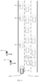
- FIG. 2 is a schematic diagram of an automated driving system to which an embodiment of this application is applicable.
- a computer system 101 includes: a processor 103, where the processor 103 is coupled to a system bus 105, the processor 103 may be one or more processors, and each processor may include one or more processor cores; a video adapter (video adapter) 107, where the video adapter may drive a display 109, and the display 109 is coupled to the system bus 105, the system bus 105 is coupled to an input/output (input/output, I/O) bus 113 through a bus bridge 111, an I/O interface 115 is coupled to the I/O bus, and the I/O interface 115 communicates with a plurality of I/O devices, for example, an input device 117 (for example, a keyboard, a mouse, or a touchscreen) and a media tray (media tray) 121 (for example, a CD-ROM or a multimedia interface); a transceiver 123 (which may transmit and/or
- the processor 103 may be any conventional processor, including a reduced instruction set computing (Reduced Instruction Set Computing, RISC) processor, a complex instruction set computer (Complex Instruction Set Computer, CISC) processor, or a combination thereof.
- the processor may be a dedicated apparatus such as an application-specific integrated circuit ASIC.
- the processor 103 may be a neural network processor or a combination of a neural network processor and the foregoing conventional processor.
- the computer system 101 may be located away from an automated driving vehicle and may wirelessly communicate with the automated driving vehicle 0.
- some processes described in this specification are performed by a processor disposed in the automated driving vehicle, and others are performed by a remote processor, including performing an action required for performing single manipulation.
- the computer 101 may communicate with a software deploying server 149 through a network interface 129.
- the network interface 129 is a hardware network interface, for example, a network interface card.
- a network 127 may be an external network, for example, Internet; or may be an internal network, for example, Ethernet or a virtual private network (Virtual Private Network, VPN).
- the network 127 may be alternatively a wireless network, for example, a Wi-Fi network or a cellular network.
- a hard disk drive interface is coupled to the system bus 105.
- a hardware drive interface is connected to a hard disk drive.
- a system memory 135 is coupled to the system bus 105. Data running in the system memory 135 may include an operating system 137 and an application program 143 of the computer 101.
- the operating system includes a shell (shell) 139 and a kernel (kernel) 141.
- the shell 139 is an interface between a user and the kernel of the operating system.
- the shell 139 is at an outermost layer of the operating system.
- the shell 139 manages interaction between the user and the operating system: waiting for a user input, interpreting the user input to the operating system, and processing various output results of the operating system.
- the kernel 141 includes parts of the operating system that are used to manage a memory, a file, a peripheral, and a system resource. Directly interacting with hardware, the kernel of the operating system usually runs processes, provides inter-process communication, and provides CPU time slice management, interruptions, memory management, I/O management, and the like.
- the application program 143 includes related programs for controlling automated driving of a vehicle, for example, a program for managing interaction between an automated driving vehicle and an obstacle on a road, a program for controlling a path or a velocity of an automated driving vehicle, and a program for controlling interaction between an automated driving vehicle and another automated driving vehicle on a road.
- the application program 143 also exists in a system of the software deploying server (deploying server) 149.
- the computer system 101 may download the application program 143 from the software deploying server (deploying server) 149.
- the application program may further include a corresponding application program used for a solution, provided in embodiments of this application, for planning a longitudinal motion parameter of a vehicle.
- a solution for planning a longitudinal motion parameter of a vehicle in embodiments of this application is specifically described below. For brevity, details are not described herein.
- a sensor 153 is associated with the computer system 101.
- the sensor 153 is configured to detect an ambient environment of the computer 101.
- the sensor 153 may detect an animal, a car, an obstacle, a crosswalk, and the like.
- the sensor may detect an ambient environment of an object such as the animal, the car, the obstacle, or the crosswalk, for example, an ambient environment of the animal, for example, another animal appearing around the animal, weather conditions, and brightness of the ambient environment.
- the sensor may be a camera, an infrared sensor, a chemical detector, a microphone, or the like.
- a controller in a process of planning a longitudinal motion parameter of a vehicle, first obtains a current state of an automated driving vehicle at a current moment and spatial-temporal prediction data of all obstacles within a preset range. For each of all the obstacles, the controller determines a conflict time and space between each obstacle and the automated driving vehicle, and determines a planned travel trajectory of the automated driving vehicle based on the conflict time and space of each obstacle. Then the controller determines a target longitudinal motion parameter from a planned travel trajectory corresponding to each target object, and sends a control instruction to a control device of the automated vehicle based on the determined target longitudinal motion parameter.
- the controller needs to determine a standard longitudinal motion parameter of the automated driving vehicle based on the spatial-temporal prediction data of all the obstacles within the preset range, in other words, the controller needs to traverse the spatial-temporal prediction data of all the obstacles within the preset range, and calculate a target longitudinal motion parameter of the automated driving vehicle for each obstacle.
- a very large amount of calculation is required for calculating the longitudinal motion parameter.
- embodiments of this application provide a new solution for planning a longitudinal velocity of a vehicle: determining, based on an occupy relationship between time-space domains of a plurality of obstacles within a preset range around a vehicle and a time-space domain of the vehicle, a spatial-temporal occupy type corresponding to each of the plurality of obstacles; selecting a target obstacle from the plurality of obstacles based on the spatial-temporal occupy type; and then planning a longitudinal velocity of the vehicle based on a spatial-temporal occupy type corresponding to the selected target obstacle and a motion state of the target obstacle.
- the controller no longer needs to traverse time-space domains of all of the plurality of obstacles to plan a longitudinal velocity of the vehicle, thereby helping reduce an amount of calculation required for calculating the longitudinal motion parameter.
- the "longitudinal” in the “longitudinal motion parameter" of the vehicle in this application may be understood as a direction that is the same as a travel direction of the vehicle.
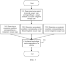
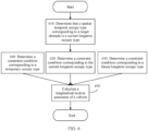
- FIG. 3 is a flowchart of a method for planning a longitudinal motion parameter of a vehicle according to an embodiment of this application.
- the method shown in FIG. 3 may be performed by a controller (for example, the control system 106 shown in FIG. 1 ).
- the method shown in FIG. 3 includes step 310 to step 350.
- 310 Detect a plurality of obstacles located within a preset range in which a vehicle is located.
- the obstacle may be understood as an object that causes a specific obstruction to a traveling process of the vehicle.
- the obstacle may be a passerby or another vehicle that crosses a lane in which the vehicle is located.
- the obstacle may be another vehicle located in front of the vehicle. This is not specifically limited in this embodiment of this application.
- the plurality of obstacles may be sensed by a vehicle-mounted sensor, where the sensor may be the camera 130 shown in FIG. 1 .
- a cloud may notify the vehicle of the plurality of obstacles within the preset range.
- the preset range may be specified by a manufacturer or set by a user. This is not specifically limited in this application.
- motion states of the plurality of obstacles may be further determined simultaneously, to subsequently determine a time-space domain of each of the plurality of obstacles.
- the motion states of the plurality of obstacles may be alternatively collected after the plurality of obstacles are determined for a period of time. This is not limited in this embodiment of this application.
- 320 Obtain a time-space domain of each of the plurality of obstacles and a time-space domain of the vehicle, where the time-space domain of each obstacle is used to indicate a change of a position space of each obstacle with time, and the time-space domain of the vehicle is used to indicate a change of a position space occupied by the vehicle with time.
- the time-space domain of each of the plurality of obstacles may be predicted based on a motion state of each of the plurality of obstacles.
- the motion state of each obstacle may include a current position, a current velocity, a current acceleration, a direction, a behavior intent, a motion trajectory within a preset time, and the like of each obstacle.
- the behavior intent may include a lane crossing intent, a lane cut-in intent, a lane forward-traveling intent, a lane bypassing intent, and the like.
- the time-space domain of each obstacle may be represented by using a pre-established coordinate system. Specifically, the time-space domain of each obstacle may be represented by using a coordinate position of each obstacle in the coordinate at different moments.
- the coordinate system may be a world coordinate system or a road coordinate system. This is not limited in this embodiment of this application.
- the world coordinate system is a coordinate system fixed relative to the ground.
- an origin of the world coordinate system may be defined at an initial position of a target object, and a positive direction of an x-axis of the world coordinate system is along a motion direction of the target object.
- the origin of the world coordinate system may be alternatively defined at a specific position on the ground, and the x-axis of the world coordinate system points north.
- a starting point of a road path may be used as an origin of the road coordinate system, a direction along the road is a positive direction of an S-axis, and a leftward direction perpendicular to the positive direction of the S-axis is a positive direction of an L-axis of the road coordinate system.
- the time-space domain of the vehicle may be predicted based on a motion state of the vehicle.
- the motion state of the vehicle may include a current position, a current velocity, a current acceleration, a direction, a behavior intent, a motion trajectory within a preset time, and the like of the vehicle.
- the time-space domain of the vehicle may be represented by using a pre-established coordinate system. Specifically, the time-space domain of the vehicle may be represented by using a coordinate position of the vehicle in the coordinate at different moments. It should be understood that the coordinate representing the time-space domain of the vehicle may be the same as the coordinate representing the obstacle. For a manner of establishing the coordinate system, refer to the foregoing descriptions. For brevity, details are not described herein again.
- 330 Determine a spatial-temporal occupy type between the time-space domain of each of the plurality of obstacles and the time-space domain of the vehicle based on an occupy time between the time-space domain of each of the plurality of obstacles and the time-space domain of the vehicle, where the occupy time is used to indicate a time period in which the position space of each of the plurality of obstacles occupies at least a part of a position of the vehicle.
- the spatial-temporal occupy type is one of a plurality of preset spatial-temporal occupy types, and the plurality of spatial-temporal occupy types include some or all of the following spatial-temporal occupy types: a current long-term occupy (current long-term occupy, CO) type, a temporary occupy (temporary occupy, TO) type, or a future long-term occupy (future long-term occupy, FO) type.
- a current long-term occupy current long-term occupy
- CO current long-term occupy
- TO temporary occupy
- FO future long-term occupy
- the spatial-temporal occupy type between the time-space domain of each of the plurality of obstacles and the time-space domain of the vehicle is the current long-term occupy type.
- the spatial-temporal occupy type between the time-space domain of each of the plurality of obstacles and the time-space domain of the vehicle is the temporary occupy type.
- the occupy time may be a period of time whose starting point is the collection moment, or may be a period of time later than the collection moment. This is not specifically limited in this embodiment of this application.
- the spatial-temporal occupy type between the time-space domain of each of the plurality of obstacles and the time-space domain of the vehicle is the future long-term occupy type.
- the first time period threshold is greater than or equal to the second time period threshold
- the third time period threshold is greater than or equal to the second time period threshold. That is, an occupy time corresponding to the current long-term occupy type is longer than an occupy time corresponding to the temporary occupy type, and an occupy time corresponding to the future long-term occupy type is longer than the occupy time corresponding to the temporary occupy type.
- the first time period threshold and the second time period threshold may be understood as a same time period threshold.
- the third time period threshold and the second time period threshold may be understood as a same time period threshold.
- the first time period threshold and the third time period threshold may be a same time period threshold, or may be different time period thresholds. This is not limited in this embodiment of this application.
- first time period threshold, the second time period threshold, and the third time period threshold may be set by the manufacturer.
- FIG. 4 For ease of understanding, the following describes a mapping relationship between different occupy times and spatial-temporal occupy types with reference to a driving scenario shown in FIG. 4 .
- Six obstacles namely, 420 to 470 shown in FIG. 4 are used as examples for description below.
- the obstacle 1, that is, the obstacle 420 is a vehicle traveling in a lane 2, and the obstacle 1 is ready to cut into the lane 1 in which the vehicle 410 is located from the lane 2, where a behavior intent of the obstacle 1, that is, the obstacle 420 is lane cut-in.
- the obstacle 2, that is, the obstacle 430 is a pedestrian ready to cross the lane 1, where a behavior intent of the obstacle 2, that is, the obstacle 430 is lane crossing.
- the obstacle 3, that is, the obstacle 440 is a pedestrian ready to cross the lane 1, where a behavior intent of the obstacle 3, that is, the obstacle 440 is lane crossing.
- the obstacles 4 to 6 450, 460, and 470 are vehicles traveling along the lane 1, where behavior intents of the obstacles 4 to 6 450, 460, and 470 are lane forward-traveling.
- the obstacle 1, that is, the obstacle 420 when a motion state of the obstacle 1, that is, the obstacle 420 is collected, the obstacle 1, that is, the obstacle 420 has not cut into the lane 1.
- a time-space domain of the obstacle 1, that is, the obstacle 420 based on the motion state of the obstacle 1, that is, the obstacle 420, it can be learned that a position space corresponding to a process from the obstacle 1, that is, the obstacle 420 starting to cut into the lane 1 to the obstacle 1, that is, the obstacle 420 having completely cut into the lane 1 and traveling along the lane 1 occupies a position space in which the vehicle 410 travels along the lane 1.
- a time period corresponding to a position space change from the obstacle 1, that is, the obstacle 420 starting to cut into the lane 1 to the obstacle 1, that is, the obstacle 420 having completely cut into the lane 1 is the occupy time in the foregoing descriptions.
- the time period corresponding to the occupy time is greater than the third time period threshold, and the occupy time is a period of time later than the collection moment.
- the obstacle 2 that is, the obstacle 430
- the obstacle 2 occupies the position space of the vehicle 410 when the obstacle 2, that is, the obstacle 430 moves from a boundary closest to the lane 1 (namely, a left boundary in FIG. 4 ) to a boundary farthest from the lane 1 (namely, a right boundary in FIG. 4 ). Therefore, a time period corresponding to a position space in which the obstacle 2, that is, the obstacle 430 moves from the boundary closest to the lane 1 (namely, the left boundary in FIG.
- the time period corresponding to the occupy time is less than the second time period threshold.
- the obstacle 3 that is, the obstacle 440
- the obstacle 3 occupies the position space of the vehicle 410 when the obstacle 3, that is, the obstacle 440 moves from a boundary closest to the lane 1 (namely, a left boundary in FIG. 4 ) to a boundary farthest from the lane 1 (namely, a right boundary in FIG. 4 ). Therefore, a time period corresponding to a position space in which the obstacle 3, that is, the obstacle 440 moves from the boundary closest to the lane 1 (namely, the left boundary in FIG.
- the time period corresponding to the occupy time is less than the second time period threshold.
- the obstacle 4, that is, the obstacle 450 when a motion state of the obstacle 4, that is, the obstacle 450 is collected, the obstacle 4, that is, the obstacle 450 is already traveling in the lane 1.
- the obstacle 4, that is, the obstacle 450 By predicting a time-space domain of the obstacle 4, that is, the obstacle 450 based on the motion state of the obstacle 4, that is, the obstacle 450, it can be learned that a position space corresponding to a process in which the obstacle 4, that is, the obstacle 450 travels along the lane 1 occupies the position space in which the vehicle 410 travels along the lane 1. Therefore, a time period corresponding to a position space change in which the obstacle 4, that is, the obstacle 450 travels along the lane 1 is the occupy time in the foregoing descriptions.
- a length of the time period corresponding to the occupy time is greater than the third time period threshold, and the occupy time is a period of time whose starting point is the collection moment.
- the obstacle 5, that is, the obstacle 460 when a motion state of the obstacle 5, that is, the obstacle 460 is collected, the obstacle 5, that is, the obstacle 460 is already traveling in the lane 1.
- the obstacle 5, that is, the obstacle 460 By predicting a time-space domain of the obstacle 5, that is, the obstacle 460 based on the motion state of the obstacle 5, that is, the obstacle 460, it can be learned that a position space corresponding to a process in which the obstacle 5, that is, the obstacle 460 travels along the lane 1 occupies the position space in which the vehicle 410 travels along the lane 1. Therefore, a time period corresponding to a position space change in which the obstacle 5, that is, the obstacle 460 travels along the lane 1 is the occupy time in the foregoing descriptions.
- a length of the time period corresponding to the occupy time is greater than the third time period threshold, and the occupy time is a period of time whose starting point is the collection moment.
- the obstacle 6, that is, the obstacle 470 when a motion state of the obstacle 6, that is, the obstacle 470 is collected, the obstacle 6, that is, the obstacle 470 is already traveling in the lane 1.
- the obstacle 6, that is, the obstacle 470 By predicting a time-space domain of the obstacle 6, that is, the obstacle 470 based on the motion state of the obstacle 6, that is, the obstacle 470, it can be learned that a position space corresponding to a process in which the obstacle 6, that is, the obstacle 470 travels along the lane 1 occupies the position space in which the vehicle 410 travels along the lane 1. Therefore, a time period corresponding to a position space change in which the obstacle 6, that is, the obstacle 470 travels along the lane 1 is the occupy time in the foregoing descriptions.
- a length of the time period corresponding to the occupy time is greater than the third time period threshold, and the occupy time is a period of time whose starting point is the collection moment.
- the target obstacle may be selected based on a longitudinal distance between an obstacle and the vehicle and/or a TTC between an obstacle and the vehicle.
- a distance between the target obstacle and the vehicle is shorter than a distance between another obstacle and the vehicle, where the another obstacle is an obstacle other than the target obstacle in the plurality of obstacles; and/or a TTC between the target obstacle and the vehicle is shorter than a TTC between the another obstacle and the vehicle.
- the target obstacle may be one or more of the plurality of obstacles. This is not limited in this embodiment of this application. Certainly, in the case of expecting to further select a quantity of target obstacles to reduce an amount of calculation required for path planning, an obstacle with a shortest distance from the vehicle may be selected from the plurality of obstacles as the target obstacle, and/or an obstacle with a shortest TTC from the vehicle may be selected from the plurality of obstacles as the target obstacle.
- the target obstacle may be selected based on a longitudinal distance between the vehicle and an obstacle belonging to the current long-term occupy type.
- a longitudinal distance between the target obstacle and the vehicle is less than a longitudinal distance between another obstacle in the plurality of obstacles and the vehicle, where the another obstacle is an obstacle other than the target obstacle in the plurality of obstacles.
- the longitudinal direction may be understood as a direction that is the same as an axial direction of the vehicle, a travel direction of the vehicle, or a heading direction of the vehicle.
- the target obstacle may be understood as one or more of the plurality of obstacles. This is not limited in this embodiment of this application. Certainly, in the case of expecting to further select a quantity of target obstacles to reduce an amount of calculation required for path planning, an obstacle with a shortest longitudinal distance from the vehicle may be selected from the plurality of obstacles as the target obstacle.
- a longitudinal distance between the obstacle 4, that is, the obstacle 450 and the vehicle 410 is less than a longitudinal distance between the obstacle 5 440 and the vehicle 410
- the longitudinal distance between the obstacle 4, that is, the obstacle 450 and the vehicle 410 is less than a longitudinal distance between the obstacle 6 450 and the vehicle 410. Therefore, the obstacle 4, that is, the obstacle 450 may be used as a target obstacle corresponding to the current long-term occupy type.
- a time to line (time to line, TTL) between an obstacle and the vehicle has large impact on the longitudinal velocity of the vehicle. Therefore, the target obstacle may be selected based on a TTL between an obstacle and the vehicle.
- a TTL between the target obstacle and the vehicle is shorter than a TTL between another obstacle and the vehicle, where the another obstacle is an obstacle other than the target obstacle in the plurality of obstacles.
- the target obstacle may be understood as one or more of the plurality of obstacles. This is not limited in this embodiment of this application. Certainly, in the case of expecting to further select a quantity of target obstacles to reduce an amount of calculation required for path planning, an obstacle with a shortest TTL from the vehicle may be selected from the plurality of obstacles as the target obstacle.
- the longitudinal motion parameter of the vehicle may include a position, in a coordinate system, to which the vehicle needs to travel at a specific moment, and an acceleration and a velocity that the vehicle needs to reach at a specific moment.
- the longitudinal motion parameter v speed goal of the vehicle indicates that a longitudinal displacement by which the vehicle needs to move in the coordinate system at a moment t is s, a velocity that the vehicle needs to reach at the moment t is v , and an acceleration is a .
- a longitudinal position of the target obstacle in the coordinate system within a planning time period being greater than a longitudinal position of the vehicle in the coordinate system may be set as a constraint condition.
- a longitudinal position of the target obstacle in the coordinate system within a planning time period being greater than a longitudinal position of the vehicle in the coordinate system may be used as a constraint condition, where a starting moment of a planning time is a moment at which the target obstacle starts to occupy the time-space domain of the vehicle within a second time period.
- a starting moment of a planning time is a moment at which the target obstacle starts to occupy the time-space domain of the vehicle within a second time period.
- that the target obstacle starts to occupy the time-space domain of the vehicle within the second time period may be understood as a cut-in moment at which the target obstacle cuts into a lane in which the vehicle travels.
- the obstacle j is an obstacle with a shortest TTL from the lane in which the vehicle travels in the plurality of obstacles, or the obstacle j is an obstacle with a shortest longitudinal distance from the vehicle in the coordinate system in the plurality of obstacles.
- Constraint condition 1 A longitudinal position of the vehicle in the coordinate system within a planning time period is less than a longitudinal position of an obstacle k in the coordinate system.
- Constraint condition 2 A longitudinal position of the vehicle in the coordinate system within a planning time period is greater than a longitudinal position of an obstacle k in the coordinate system, and the longitudinal position of the vehicle in the coordinate system is less than a longitudinal position of an obstacle l in the coordinate system.
- Constraint condition 3 A longitudinal position of the vehicle in the coordinate system within a planning time period is greater than a longitudinal position of an obstacle l in the coordinate system.
- the obstacle k is an obstacle with a shortest longitudinal distance from the vehicle in the coordinate system in the plurality of obstacles.
- the obstacle l is an obstacle with a shortest TTC from the vehicle in the plurality of obstacles.
- the foregoing describes methods for setting constraint conditions based on three different spatial-temporal occupy types.
- the following describes a method for planning a longitudinal motion parameter of a vehicle with reference to the constraint conditions described above.
- constraint conditions corresponding to the other two spatial-temporal occupy types may be combined to plan the longitudinal motion parameter of the vehicle.
- the foregoing method further includes: planning the longitudinal motion parameter of the vehicle based on the spatial-temporal occupy type corresponding to the target obstacle and a motion state of the target obstacle, including: determining, based on the spatial-temporal occupy type corresponding to the target obstacle and the motion state of the target obstacle, a first constraint condition corresponding to the spatial-temporal occupy type of the target obstacle, where the first constraint condition is used to constrain the longitudinal motion parameter of the vehicle, to avoid collision between the target obstacle and the vehicle; obtaining a second constraint condition corresponding to another spatial-temporal occupy type, where the another spatial-temporal occupy type is a spatial-temporal occupy type other than the spatial-temporal occupy type in a plurality of spatial-temporal occupy types, and the second constraint condition is used to constrain the longitudinal motion parameter of the vehicle, to avoid collision between the vehicle and an obstacle corresponding to the another spatial-temporal occupy type; and calculating the longitudinal motion parameter of the vehicle based on the first constraint condition and the second constraint condition.
- the spatial-temporal occupy type corresponding to the target obstacle may be one of the foregoing three spatial-temporal occupy types.
- the another spatial-temporal occupy type may be a spatial-temporal occupy type other than the spatial-temporal occupy type corresponding to the target obstacle in the three spatial-temporal occupy types.
- the another spatial-temporal occupy type may include the temporary occupy type and the current long-term occupy type.
- the another spatial-temporal occupy type may include the temporary occupy type.
- the following describes a method for calculating a longitudinal motion parameter of a vehicle by using an example in which the spatial-temporal occupy type corresponding to the target obstacle is the current long-term occupy type and the another spatial-temporal occupy type includes the future long-term occupy type and the temporary occupy type. It should be noted that, the following mainly describes a method for calculating a longitudinal motion parameter of a vehicle. For constraint conditions of various spatial-temporal occupy types included in the method, refer to the foregoing descriptions. For brevity, details are not described herein again.
- FIG. 5 is a schematic diagram of a method for calculating a longitudinal motion parameter of a vehicle according to an embodiment of this application.
- the method shown in FIG. 5 includes step 510 to step 550.
- FIG. 6 is a schematic diagram of a method for calculating a longitudinal motion parameter of a vehicle according to another embodiment of this application.
- the method shown in FIG. 6 includes step 610 to step 650.
- FIG. 7 is a schematic diagram of a method for calculating a longitudinal motion parameter of a vehicle according to another embodiment of this application.
- the method shown in FIG. 7 includes step 710 to step 750.
- a longitudinal motion parameter of the vehicle may be separately planned based on the constraint conditions corresponding to the foregoing three spatial-temporal occupy types. This is not limited in embodiments of this application.
- the longitudinal motion parameter of the vehicle may be further verified. Specifically, collision risk verification is performed on the longitudinal motion parameter of the vehicle that is calculated for the foregoing three spatial-temporal occupy types, to ensure safety of a finally output longitudinal motion parameter of the vehicle.
- the collision risk verification may be performing calculation and solution based on a displacement-time graph (ST graph).
- ST graph displacement-time graph
- all target obstacles are projected into the ST graph, and if collision occurs with none of all the target obstacles in a process of reaching a position corresponding to the longitudinal motion parameter from a current position of the vehicle, it can be considered that the position corresponding to the longitudinal motion parameter is safe.
- FIG. 8 is a flowchart of a method for planning a longitudinal motion parameter of a vehicle according to an embodiment of this application.
- the method shown in FIG. 8 includes step 810 to step 850.
- a current position of an object (a vehicle or an obstacle) corresponding to a motion state in a coordinate system is denoted as "Position”
- an x-axis in the coordinate system corresponds to a travel direction of the vehicle
- a y-axis in the coordinate system is perpendicular to the travel direction of the vehicle.
- a current velocity of the object may be denoted as “Velocity”
- a current acceleration of the object may be denoted as “Acceleration”
- a heading direction of the object may be denoted as "Heading”.
- Case 1 If a motion state of the obstacle includes intent information of the obstacle, the spatial-temporal occupy type corresponding to the obstacle may be directly determined based on the intent information of the obstacle.
- an intent of the obstacle may be defined as ⁇ lane crossing intent, lane cut-in intent, lane forward-traveling intent, lane bypassing intent ⁇ .
- the lane crossing intent and the lane bypassing intent may correspond to a temporary spatial-temporal occupy type.
- the lane cut-in intent may correspond to a future long-term spatial-temporal occupy type.
- the lane forward-traveling intent may correspond to a current long-term spatial-temporal occupy type.
- I object1 the lane cut-in intent, and the obstacle 1, that is, the obstacle 420 belongs to the future long-term spatial-temporal occupy type
- I object2 the lane crossing intent, and the obstacle 2, that is, the obstacle 430 belongs to the temporary occupy type
- I object3 the lane crossing intent, and the obstacle 3, that is, the obstacle 440 belongs to the temporary occupy type
- I object4 the lane forward-traveling intent, and the obstacle 4, that is, the obstacle 450 belongs to the current long-term occupy type
- I object5 the lane forward-traveling intent, and the obstacle 5, that is, the obstacle 460 belongs to the current long-term occupy type
- I object6 the lane forward-traveling intent, and obstacle 6, that is, the obstacle 470 belongs to the current long-term occupy type.
- Case 2 If a motion state of the obstacle includes trajectory prediction information but does not include behavior intent information, the spatial-temporal occupy type corresponding to each obstacle may be determined through spatial projection calculation in this case.
- a positive direction of an S-axis represents a direction in which the vehicle travels along a road
- a positive direction of an L-axis represents a direction perpendicular to the S-axis
- a t-axis represents time.
- S 0 , L 0 , and t 0 are coordinate origins of the S-axis, the L-axis, and the t-axis respectively.
- a road coordinate system is constructed by using the travel path of the vehicle 410 as a reference line, and it is learned that coordinates of the obstacle 4, that is, the obstacle 450 in the coordinate system are ( s object4_0 , l object4_0 ), coordinates of the obstacle 5 450 in the coordinate system are ( s 0bject5_0 , l object5_0 ), and coordinates of the obstacle 6, that is, the obstacle 470 in the coordinate system are ( s object6_0 , l object50 ).
- s object4_0 > s object5_0 > s object6_0 only the obstacle 4 and the obstacle 5 need to be considered for setting the constraint condition corresponding to the CO type, that is, a target obstacle corresponding to the CO type includes the obstacle 4 and the obstacle 5.
- the constraint condition corresponding to the current long-term occupy type is as follows: ⁇ s t ⁇ s object 4 , t ⁇ 0 T and s t > s object 5 , t ⁇ 0 T .
- the CO type there may be one or two target obstacles corresponding to the CO type. This is not specifically limited in this embodiment of this application. Certainly, if motion states of two target obstacles are considered, this helps improve safety of planning of a longitudinal motion parameter of the vehicle. For example, in a vehicle following scenario, only a front vehicle is considered, and a vehicle in front of the front vehicle is not considered. In this case, there may be a problem that a travel velocity of a current vehicle cannot be handled in a timely manner when the vehicle in front of the front vehicle has an emergency.
- the obstacle 1 is an obstacle with a shortest TTL time from a lane in which the vehicle is located in the plurality of obstacles. Therefore, the obstacle 1 may be used as a target obstacle corresponding to the future long-term occupy type.
- a road coordinate system is constructed by using the travel path of the vehicle 410 as a reference line, and it is learned that coordinates of the obstacle 1 in the coordinate system are (s object1_0 , l object1_0 ).
- the constraint condition corresponding to the future long-term occupy type is ⁇ s t ⁇ s object 1 , t ⁇ 0 T or s t > s object 1 , t ⁇ ttl object 1 T , where T indicates a planning time for a longitudinal motion parameter of the vehicle.
- the obstacle 2 is an obstacle with a shortest longitudinal distance from the vehicle in a road coordinate system
- the obstacle 3 is an obstacle with a shortest TTC from the vehicle in the plurality of obstacles. Therefore, the obstacle 2 and the obstacle 3 may be used as target obstacles corresponding to the temporary occupy type.
- a road coordinate system is constructed by using the travel path of the vehicle 410 as a reference line, and it is learned that coordinates of the obstacle 2 are ( s object2_0 , l object2_0 ), and coordinates of the obstacle 3 are ( s object3_0 , l object5_0 ).
- the constraint condition of the TO type is as follows: ⁇ s t ⁇ s object 2 , t ⁇ t object 2 _ in t object 2 _ out or s t > s object 3 , t ⁇ t object 3 _ in t object 3 _ out or s object 2 ⁇ s t ⁇ s object 3 , t ⁇ t object 2 _ in t object 3 _ out .
- a determining condition is s object 4 - t HWT ⁇ v object 4 ⁇ s object 5 - t HWT ⁇ v object 5 and t object 4 ⁇ t object 5 . If the determining condition is not met, a longitudinal motion parameter with the smallest s of the two longitudinal motion parameters is used; or if the condition is met, the two longitudinal motion parameters are retained.
- the retained longitudinal motion parameter meets the constraint condition corresponding to the FO type and the constraint condition corresponding to the TO type is determined through calculation. If the constraint condition corresponding to the FO type and the constraint condition corresponding to the TO type are met, the retained longitudinal motion parameter is used as a longitudinal motion parameter speedgoal co planned based on an obstacle of the CO type. If the constraint condition corresponding to the FO type and/or the constraint condition corresponding to the TO type is not met, one of the retained longitudinal motion parameter, a longitudinal motion parameter calculated based on an obstacle of the FO type, and a longitudinal motion parameter calculated based on the obstacle of the TO type, whichever has the smallest s, is used as an output.
- the target obstacle corresponding to the FO type is the obstacle 1.
- a longitudinal motion parameter corresponding to a point with the smallest s, of the conservative longitudinal motion parameter, the longitudinal motion parameter of the CO type, and the longitudinal motion parameter of the TO type is used as an output.
- the target obstacles corresponding to the TO type are the obstacle 2 and the obstacle 3.
- a determining condition is s object 2 - C ⁇ s object 3 - C and t object 2 _in ⁇ t object 3 _in . If the determining condition is not met, a longitudinal motion parameter with the smallest s of the two longitudinal motion parameters is used; or if the determining condition is met, the two longitudinal motion parameters are retained.
- Collision risk verification is performed on calculation results of the foregoing modules to ensure safety of a final output result.
- the collision risk verification may be performing calculation and solution based on an ST graph (displacement-time graph). All target obstacles are projected into the ST graph, and it is determined whether reaching positions of the planned longitudinal motion parameters from a position of the vehicle 410 without collision with any target obstacle is possible. As shown in FIG. 12 , provided that a longitudinal motion parameter falls within an interval enclosed by dashed lines, the longitudinal motion parameter is considered safe, and the verification succeeds.
- maxS(t) which is a boundary condition of S(t)
- an objective optimization function is constructed by using a cubic polynomial, but the cubic polynomial does not constitute a limitation.
- FIG. 13 is a schematic diagram of an apparatus for planning a longitudinal motion parameter of a vehicle according to an embodiment of this application.
- the apparatus 1300 shown in FIG. 13 includes a detection unit 1310, an obtaining unit 1320, and a processing unit 1320.
- the detection unit 1310 is configured to detect a plurality of obstacles located within a preset range of the vehicle.
- the obtaining unit 1320 is configured to obtain a time-space domain of each of the plurality of obstacles and a time-space domain of the vehicle, where the time-space domain of each obstacle is used to indicate a change of a position space of each obstacle with time, and the time-space domain of the vehicle is used to indicate a change of a position space occupied by the vehicle with time.
- the processing unit 1330 is configured to determine a spatial-temporal occupy type between the time-space domain of each of the plurality of obstacles and the time-space domain of the vehicle based on an occupy time between the time-space domain of each of the plurality of obstacles and the time-space domain of the vehicle, where the occupy time is used to indicate a time period in which the position space of each of the plurality of obstacles occupies at least a part of a position of the vehicle.
- the processing unit 1330 is further configured to select a target obstacle from the plurality of obstacles based on the spatial-temporal occupy type.
- the processing unit 1330 is further configured to plan a longitudinal motion parameter of the vehicle based on a spatial-temporal occupy type corresponding to the target obstacle.
- the spatial-temporal occupy type between the time-space domain of each of the plurality of obstacles and the time-space domain of the vehicle is the current long-term occupy type
- a distance between the target obstacle and the vehicle is shorter than a distance between another obstacle and the vehicle, where the another obstacle is an obstacle other than the target obstacle in the plurality of obstacles; or a time to collision TTC between the target obstacle and the vehicle is shorter than a TTC between the another obstacle and the vehicle.
- a longitudinal distance between the target obstacle and the vehicle is less than a longitudinal distance between another obstacle in the plurality of obstacles and the vehicle.
- a time to line TTL between the target obstacle and a lane in which the vehicle travels is shorter than a TTL between another obstacle and the lane, where the another obstacle is an obstacle other than the target obstacle in the plurality of obstacles.
- the processing unit 1330 is further configured to: determine, based on the spatial-temporal occupy type corresponding to the target obstacle, a first constraint condition corresponding to the spatial-temporal occupy type of the target obstacle, where the first constraint condition is used to constrain the longitudinal motion parameter of the vehicle, to avoid collision between the target obstacle and the vehicle; obtain a second constraint condition corresponding to another spatial-temporal occupy type, where the another spatial-temporal occupy type is a spatial-temporal occupy type other than the spatial-temporal occupy type in a plurality of spatial-temporal occupy types, and the second constraint condition is used to constrain the longitudinal motion parameter of the vehicle, to avoid collision between the vehicle and an obstacle corresponding to the another spatial-temporal occupy type; and plan the longitudinal motion parameter of the vehicle based on the first constraint condition and the second constraint condition.
- the detection unit 1310 and the obtaining unit 1320 may be a communication interface 1430
- the processing unit 1330 may be a processor 1420
- the controller may further include a memory 1410, as specifically shown in FIG. 14 .
- FIG. 14 is a schematic block diagram of a controller according to another embodiment of this application.
- the controller 1400 shown in FIG. 14 may include the memory 1410, the processor 1420, and the communication interface 1430.
- the memory 1410, the processor 1420, and the communication interface 1430 are connected through an internal connection path.
- the memory 1410 is configured to store instructions.
- the processor 1420 is configured to execute the instructions stored in the memory 1420, to control the input/output interface 1430 to send/receive at least some parameters of a second channel model.
- the memory 1410 may be coupled to the processor 1420 through an interface, or may be integrated with the processor 1420.
- the communication interface 1430 uses a transceiver apparatus, for example, but not limited to, a transceiver, to implement communication between the communication device 1400 and another device or a communication network.
- the communication interface 1430 may further include an input/output interface (input/output interface).
- the steps in the foregoing method may be implemented by using a hardware integrated logical circuit in the processor 1420 or instructions in a form of software.
- the method disclosed with reference to embodiments of this application may be directly performed by a hardware processor, or may be performed by using a combination of hardware in the processor and a software module.
- the software module may be located in a mature storage medium in the art, such as a random access memory, a flash memory, a read-only memory, a programmable read-only memory, an electrically erasable programmable memory, or a register.
- the storage medium is located in the memory 1410, and the processor 1420 reads information in the memory 1410 and completes the steps in the foregoing methods in combination with hardware of the processor. To avoid repetition, details are not described herein again.
- the processor in embodiments of this application may be a central processing unit (central processing unit, CPU).
- the processor may be another general-purpose processor, a digital signal processor (digital signal processor, DSP), an application-specific integrated circuit (application-specific integrated circuit, ASIC), a field programmable gate array (field programmable gate array, FPGA) or another programmable logic device, a discrete gate or transistor logic device, a discrete hardware component, or the like.
- the general-purpose processor may be a microprocessor, or the processor may be any conventional processor or the like.
- the memory may include a read-only memory and a random access memory, and provide instructions and data to the processor.
- a part of the processor may further include a nonvolatile random access memory.
- the processor may further store information about a device type.
- sequence numbers of the foregoing processes do not mean execution sequences in embodiments of this application.
- the execution sequences of the processes should be determined based on functions and internal logic of the processes, and should not constitute any limitation on implementation processes of embodiments of this application.
- the disclosed system, apparatus, and method may be implemented in another manner.
- the described apparatus embodiment is merely an example.
- division into the units is merely logical function division and may be other division in actual implementation.
- a plurality of units or components may be combined or integrated into another system, or some features may be ignored or not performed.
- the displayed or discussed mutual couplings or direct couplings or communication connections may be implemented through some interfaces.
- the indirect couplings or communication connections between the apparatuses or units may be implemented in electrical, mechanical, or another form.
- the units described as separate parts may or may not be physically separate, and parts displayed as units may or may not be physical units, and may be located in one position, or may be distributed on a plurality of network units. Some or all of the units may be selected based on actual requirements to achieve the objectives of the solutions of embodiments.
- the functions When the functions are implemented in a form of a software functional unit and sold or used as an independent product, the functions may be stored in a computer-readable storage medium. Based on such an understanding, the technical solutions of this application essentially, or the part contributing to the conventional technology, or some of the technical solutions may be implemented in a form of a software product.
- the computer software product is stored in a storage medium, and includes several instructions for instructing a computer device (which may be a personal computer, a server, a network device, or the like) to perform all or some of the steps of the methods described in embodiments of this application.
- the foregoing storage medium includes any medium that can store program code, such as a USB flash drive, a removable hard disk, a read-only memory (read-only memory, ROM), a random access memory (random access memory, RAM), a magnetic disk, or an optical disc.
- program code such as a USB flash drive, a removable hard disk, a read-only memory (read-only memory, ROM), a random access memory (random access memory, RAM), a magnetic disk, or an optical disc.
Landscapes
- Engineering & Computer Science (AREA)
- Automation & Control Theory (AREA)
- Transportation (AREA)
- Mechanical Engineering (AREA)
- Human Computer Interaction (AREA)
- Traffic Control Systems (AREA)
- Control Of Driving Devices And Active Controlling Of Vehicle (AREA)
Applications Claiming Priority (2)
| Application Number | Priority Date | Filing Date | Title |
|---|---|---|---|
| CN202010545611.XA CN113799794B (zh) | 2020-06-16 | 2020-06-16 | 车辆纵向运动参数的规划方法和装置 |
| PCT/CN2021/090824 WO2021254000A1 (fr) | 2020-06-16 | 2021-04-29 | Procédé et dispositif de planification de paramètres de mouvement longitudinal de véhicule |
Publications (2)
| Publication Number | Publication Date |
|---|---|
| EP4159564A1 true EP4159564A1 (fr) | 2023-04-05 |
| EP4159564A4 EP4159564A4 (fr) | 2023-12-06 |
Family
ID=78944266
Family Applications (1)
| Application Number | Title | Priority Date | Filing Date |
|---|---|---|---|
| EP21824973.8A Pending EP4159564A4 (fr) | 2020-06-16 | 2021-04-29 | Procédé et dispositif de planification de paramètres de mouvement longitudinal de véhicule |
Country Status (3)
| Country | Link |
|---|---|
| EP (1) | EP4159564A4 (fr) |
| CN (1) | CN113799794B (fr) |
| WO (1) | WO2021254000A1 (fr) |
Families Citing this family (2)
| Publication number | Priority date | Publication date | Assignee | Title |
|---|---|---|---|---|
| CN114475587B (zh) * | 2022-01-30 | 2024-04-30 | 重庆长安汽车股份有限公司 | 引入目标行为及碰撞概率的风险评估算法 |
| CN115384552B (zh) * | 2022-09-29 | 2024-09-06 | 阿波罗智能技术(北京)有限公司 | 自动驾驶车辆的控制方法、装置和自动驾驶车辆 |
Family Cites Families (15)
| Publication number | Priority date | Publication date | Assignee | Title |
|---|---|---|---|---|
| JP4211794B2 (ja) * | 2006-02-28 | 2009-01-21 | トヨタ自動車株式会社 | 干渉評価方法、装置、およびプログラム |
| EP2950114B1 (fr) * | 2014-05-30 | 2020-03-04 | Honda Research Institute Europe GmbH | Procédé pour assister un conducteur lors de l'entraînement d'un véhicule, système d'assistance au conducteur, produit de programme logiciel informatique et véhicule |
| US10286913B2 (en) * | 2016-06-23 | 2019-05-14 | Honda Motor Co., Ltd. | System and method for merge assist using vehicular communication |
| KR101982298B1 (ko) * | 2016-11-24 | 2019-05-24 | 고려대학교 산학협력단 | 차량에서의 돌발적으로 출현한 이동 객체를 탐지하는 방법 및 장치 |
| JP6558393B2 (ja) * | 2017-04-06 | 2019-08-14 | トヨタ自動車株式会社 | 進路設定装置及び進路設定方法 |
| US10569772B2 (en) * | 2017-04-12 | 2020-02-25 | Hrl Laboratories, Llc | Cognitive behavior prediction system for autonomous systems |
| US10710579B2 (en) * | 2017-06-01 | 2020-07-14 | Waymo Llc | Collision prediction system |
| JP6524144B2 (ja) * | 2017-06-02 | 2019-06-05 | 本田技研工業株式会社 | 車両制御システム及び方法、並びに走行支援サーバ |
| US10579063B2 (en) * | 2017-07-21 | 2020-03-03 | Uatc, Llc | Machine learning for predicting locations of objects perceived by autonomous vehicles |
| JP2019038314A (ja) * | 2017-08-23 | 2019-03-14 | トヨタ自動車株式会社 | 車両運転支援装置 |
| CN110352153B (zh) * | 2018-02-02 | 2024-07-19 | 辉达公司 | 自主车辆中用于障碍物躲避的安全程序分析 |
| CN108875998A (zh) * | 2018-04-20 | 2018-11-23 | 北京智行者科技有限公司 | 一种自动驾驶车辆规划方法和系统 |
| TWI674984B (zh) * | 2018-11-15 | 2019-10-21 | 財團法人車輛研究測試中心 | 自動駕駛車輛之行駛軌跡規劃系統及方法 |
| KR20200075915A (ko) * | 2018-12-07 | 2020-06-29 | 현대자동차주식회사 | 차량의 주행 제어 장치 및 그 방법 |
| CN110356394B (zh) * | 2019-07-31 | 2020-09-08 | 重庆长安汽车股份有限公司 | 一种车辆主动避让障碍物的方法、装置及汽车 |
-
2020
- 2020-06-16 CN CN202010545611.XA patent/CN113799794B/zh active Active
-
2021
- 2021-04-29 EP EP21824973.8A patent/EP4159564A4/fr active Pending
- 2021-04-29 WO PCT/CN2021/090824 patent/WO2021254000A1/fr unknown
Also Published As
| Publication number | Publication date |
|---|---|
| WO2021254000A1 (fr) | 2021-12-23 |
| CN113799794B (zh) | 2023-05-09 |
| CN113799794A (zh) | 2021-12-17 |
| EP4159564A4 (fr) | 2023-12-06 |
Similar Documents
| Publication | Publication Date | Title |
|---|---|---|
| US12061088B2 (en) | Obstacle avoidance method and apparatus | |
| EP4067821A1 (fr) | Procédé et appareil de planification de trajet pour véhicule | |
| US20220379920A1 (en) | Trajectory planning method and apparatus | |
| JP7540641B2 (ja) | 自動運転方法、関連装置及びコンピュータ読み取り可能記憶媒体 | |
| CN110379193B (zh) | 自动驾驶车辆的行为规划方法及行为规划装置 | |
| WO2021196879A1 (fr) | Procédé et dispositif de reconnaissance du comportement de conduite d'un véhicule | |
| CN113968216B (zh) | 一种车辆碰撞检测方法、装置及计算机可读存储介质 | |
| WO2021000800A1 (fr) | Procédé de raisonnement pour la région roulable d'une route, et dispositif | |
| CN113160547B (zh) | 一种自动驾驶方法及相关设备 | |
| US20230048680A1 (en) | Method and apparatus for passing through barrier gate crossbar by vehicle | |
| WO2022062825A1 (fr) | Procédé, dispositif de commande de véhicule et véhicule | |
| US20230211809A1 (en) | Autonomous driving method and apparatus | |
| EP4159564A1 (fr) | Procédé et dispositif de planification de paramètres de mouvement longitudinal de véhicule | |
| EP4202759A1 (fr) | Procédé de détection de ligne de voie de circulation, dispositif associé et support de stockage lisible par ordinateur | |
| EP4246492A1 (fr) | Procédé et dispositif de commande | |
| EP4428643A1 (fr) | Procédé et dispositif de contrainte de trajet | |
| CN117944671A (zh) | 一种目标行为预测方法、智能设备及车辆 | |
| EP4130921A1 (fr) | Procédé d'optimisation de la régulation et de la commande de prise de décision, procédé de commande de déplacement de véhicule et dispositifs associés | |
| EP4194299A1 (fr) | Procédé et appareil pour planification de trajectoire de changement de file | |
| WO2023015510A1 (fr) | Procédé d'évitement de collision et appareil de commande | |
| EP4167126A1 (fr) | Procédé d'inférence de voie et procédé et appareil d'entraînement de modèle d'inférence de voie | |
| WO2022061725A1 (fr) | Procédé et appareil d'observation d'élément de circulation | |
| WO2021097823A1 (fr) | Procédé et dispositif destinés à être utilisés pour déterminer un espace pouvant être traversé par un véhicule |
Legal Events
| Date | Code | Title | Description |
|---|---|---|---|
| STAA | Information on the status of an ep patent application or granted ep patent |
Free format text: STATUS: THE INTERNATIONAL PUBLICATION HAS BEEN MADE |
|
| PUAI | Public reference made under article 153(3) epc to a published international application that has entered the european phase |
Free format text: ORIGINAL CODE: 0009012 |
|
| STAA | Information on the status of an ep patent application or granted ep patent |
Free format text: STATUS: REQUEST FOR EXAMINATION WAS MADE |
|
| 17P | Request for examination filed |
Effective date: 20221227 |
|
| AK | Designated contracting states |
Kind code of ref document: A1 Designated state(s): AL AT BE BG CH CY CZ DE DK EE ES FI FR GB GR HR HU IE IS IT LI LT LU LV MC MK MT NL NO PL PT RO RS SE SI SK SM TR |
|
| DAV | Request for validation of the european patent (deleted) | ||
| DAX | Request for extension of the european patent (deleted) | ||
| REG | Reference to a national code |
Ref country code: DE Ref legal event code: R079 Free format text: PREVIOUS MAIN CLASS: B60W0030090000 Ipc: B60W0030140000 |
|
| A4 | Supplementary search report drawn up and despatched |
Effective date: 20231108 |
|
| RIC1 | Information provided on ipc code assigned before grant |
Ipc: B60W 60/00 20200101ALI20231102BHEP Ipc: B60W 30/095 20120101ALI20231102BHEP Ipc: B60W 40/04 20060101ALI20231102BHEP Ipc: B60W 30/09 20120101ALI20231102BHEP Ipc: B60W 30/14 20060101AFI20231102BHEP |