EP4159118A1 - Cuff-less method for determining a user's blood pressure - Google Patents
Cuff-less method for determining a user's blood pressure Download PDFInfo
- Publication number
- EP4159118A1 EP4159118A1 EP22198522.9A EP22198522A EP4159118A1 EP 4159118 A1 EP4159118 A1 EP 4159118A1 EP 22198522 A EP22198522 A EP 22198522A EP 4159118 A1 EP4159118 A1 EP 4159118A1
- Authority
- EP
- European Patent Office
- Prior art keywords
- acoustic
- photodetector
- light source
- optical
- signal
- Prior art date
- Legal status (The legal status is an assumption and is not a legal conclusion. Google has not performed a legal analysis and makes no representation as to the accuracy of the status listed.)
- Pending
Links
- 230000036772 blood pressure Effects 0.000 title claims abstract description 18
- 238000000034 method Methods 0.000 title claims description 20
- 230000003287 optical effect Effects 0.000 claims abstract description 89
- 210000001367 artery Anatomy 0.000 claims description 61
- 238000005259 measurement Methods 0.000 claims description 37
- 230000002123 temporal effect Effects 0.000 claims description 29
- 230000004872 arterial blood pressure Effects 0.000 claims description 21
- 230000005855 radiation Effects 0.000 claims description 14
- 230000004913 activation Effects 0.000 claims description 10
- 238000002592 echocardiography Methods 0.000 claims description 9
- 230000015572 biosynthetic process Effects 0.000 claims description 6
- 230000003595 spectral effect Effects 0.000 claims description 6
- 230000008569 process Effects 0.000 claims description 4
- 230000001902 propagating effect Effects 0.000 claims description 4
- 238000001514 detection method Methods 0.000 claims description 3
- 230000006870 function Effects 0.000 description 16
- 238000012545 processing Methods 0.000 description 13
- 230000006835 compression Effects 0.000 description 8
- 238000007906 compression Methods 0.000 description 8
- 230000000694 effects Effects 0.000 description 8
- 210000001519 tissue Anatomy 0.000 description 8
- 210000004369 blood Anatomy 0.000 description 7
- 239000008280 blood Substances 0.000 description 7
- 230000000747 cardiac effect Effects 0.000 description 7
- 230000000737 periodic effect Effects 0.000 description 7
- 238000000926 separation method Methods 0.000 description 7
- 230000000875 corresponding effect Effects 0.000 description 5
- 238000009530 blood pressure measurement Methods 0.000 description 4
- 230000002596 correlated effect Effects 0.000 description 3
- 239000013307 optical fiber Substances 0.000 description 3
- 230000010355 oscillation Effects 0.000 description 3
- 230000000541 pulsatile effect Effects 0.000 description 3
- 239000000523 sample Substances 0.000 description 3
- 102000001554 Hemoglobins Human genes 0.000 description 2
- 108010054147 Hemoglobins Proteins 0.000 description 2
- 238000010521 absorption reaction Methods 0.000 description 2
- 230000005540 biological transmission Effects 0.000 description 2
- 238000012512 characterization method Methods 0.000 description 2
- 230000007423 decrease Effects 0.000 description 2
- 230000035487 diastolic blood pressure Effects 0.000 description 2
- 230000008034 disappearance Effects 0.000 description 2
- 210000003414 extremity Anatomy 0.000 description 2
- 210000003205 muscle Anatomy 0.000 description 2
- 230000000644 propagated effect Effects 0.000 description 2
- 238000004088 simulation Methods 0.000 description 2
- 230000035488 systolic blood pressure Effects 0.000 description 2
- 208000031104 Arterial Occlusive disease Diseases 0.000 description 1
- 208000031968 Cadaver Diseases 0.000 description 1
- 241000861223 Issus Species 0.000 description 1
- 241001080024 Telles Species 0.000 description 1
- 230000002159 abnormal effect Effects 0.000 description 1
- 230000003213 activating effect Effects 0.000 description 1
- 239000000853 adhesive Substances 0.000 description 1
- 230000001070 adhesive effect Effects 0.000 description 1
- 238000004458 analytical method Methods 0.000 description 1
- 208000021328 arterial occlusion Diseases 0.000 description 1
- 230000008901 benefit Effects 0.000 description 1
- 230000017531 blood circulation Effects 0.000 description 1
- 238000004364 calculation method Methods 0.000 description 1
- 210000001715 carotid artery Anatomy 0.000 description 1
- 230000008878 coupling Effects 0.000 description 1
- 238000010168 coupling process Methods 0.000 description 1
- 238000005859 coupling reaction Methods 0.000 description 1
- 238000013461 design Methods 0.000 description 1
- 238000011161 development Methods 0.000 description 1
- 230000018109 developmental process Effects 0.000 description 1
- 230000004882 diastolic arterial blood pressure Effects 0.000 description 1
- 230000031700 light absorption Effects 0.000 description 1
- 238000012544 monitoring process Methods 0.000 description 1
- 230000008447 perception Effects 0.000 description 1
- 230000010363 phase shift Effects 0.000 description 1
- 238000013186 photoplethysmography Methods 0.000 description 1
- 210000002321 radial artery Anatomy 0.000 description 1
- 238000007430 reference method Methods 0.000 description 1
- 230000004044 response Effects 0.000 description 1
- 238000005070 sampling Methods 0.000 description 1
- 210000003491 skin Anatomy 0.000 description 1
- 230000004873 systolic arterial blood pressure Effects 0.000 description 1
- 210000003462 vein Anatomy 0.000 description 1
- 210000000707 wrist Anatomy 0.000 description 1
Images


Classifications
-
- A—HUMAN NECESSITIES
- A61—MEDICAL OR VETERINARY SCIENCE; HYGIENE
- A61B—DIAGNOSIS; SURGERY; IDENTIFICATION
- A61B5/00—Measuring for diagnostic purposes; Identification of persons
- A61B5/02—Detecting, measuring or recording pulse, heart rate, blood pressure or blood flow; Combined pulse/heart-rate/blood pressure determination; Evaluating a cardiovascular condition not otherwise provided for, e.g. using combinations of techniques provided for in this group with electrocardiography or electroauscultation; Heart catheters for measuring blood pressure
- A61B5/021—Measuring pressure in heart or blood vessels
- A61B5/02108—Measuring pressure in heart or blood vessels from analysis of pulse wave characteristics
- A61B5/02125—Measuring pressure in heart or blood vessels from analysis of pulse wave characteristics of pulse wave propagation time
-
- A—HUMAN NECESSITIES
- A61—MEDICAL OR VETERINARY SCIENCE; HYGIENE
- A61B—DIAGNOSIS; SURGERY; IDENTIFICATION
- A61B5/00—Measuring for diagnostic purposes; Identification of persons
- A61B5/02—Detecting, measuring or recording pulse, heart rate, blood pressure or blood flow; Combined pulse/heart-rate/blood pressure determination; Evaluating a cardiovascular condition not otherwise provided for, e.g. using combinations of techniques provided for in this group with electrocardiography or electroauscultation; Heart catheters for measuring blood pressure
- A61B5/021—Measuring pressure in heart or blood vessels
- A61B5/02108—Measuring pressure in heart or blood vessels from analysis of pulse wave characteristics
- A61B5/02116—Measuring pressure in heart or blood vessels from analysis of pulse wave characteristics of pulse wave amplitude
-
- A—HUMAN NECESSITIES
- A61—MEDICAL OR VETERINARY SCIENCE; HYGIENE
- A61B—DIAGNOSIS; SURGERY; IDENTIFICATION
- A61B5/00—Measuring for diagnostic purposes; Identification of persons
- A61B5/02—Detecting, measuring or recording pulse, heart rate, blood pressure or blood flow; Combined pulse/heart-rate/blood pressure determination; Evaluating a cardiovascular condition not otherwise provided for, e.g. using combinations of techniques provided for in this group with electrocardiography or electroauscultation; Heart catheters for measuring blood pressure
- A61B5/024—Detecting, measuring or recording pulse rate or heart rate
- A61B5/02416—Detecting, measuring or recording pulse rate or heart rate using photoplethysmograph signals, e.g. generated by infrared radiation
- A61B5/02427—Details of sensor
- A61B5/02433—Details of sensor for infrared radiation
-
- A—HUMAN NECESSITIES
- A61—MEDICAL OR VETERINARY SCIENCE; HYGIENE
- A61B—DIAGNOSIS; SURGERY; IDENTIFICATION
- A61B5/00—Measuring for diagnostic purposes; Identification of persons
- A61B5/02—Detecting, measuring or recording pulse, heart rate, blood pressure or blood flow; Combined pulse/heart-rate/blood pressure determination; Evaluating a cardiovascular condition not otherwise provided for, e.g. using combinations of techniques provided for in this group with electrocardiography or electroauscultation; Heart catheters for measuring blood pressure
- A61B5/026—Measuring blood flow
- A61B5/0261—Measuring blood flow using optical means, e.g. infrared light
-
- A—HUMAN NECESSITIES
- A61—MEDICAL OR VETERINARY SCIENCE; HYGIENE
- A61B—DIAGNOSIS; SURGERY; IDENTIFICATION
- A61B5/00—Measuring for diagnostic purposes; Identification of persons
- A61B5/103—Detecting, measuring or recording devices for testing the shape, pattern, colour, size or movement of the body or parts thereof, for diagnostic purposes
- A61B5/107—Measuring physical dimensions, e.g. size of the entire body or parts thereof
- A61B5/1075—Measuring physical dimensions, e.g. size of the entire body or parts thereof for measuring dimensions by non-invasive methods, e.g. for determining thickness of tissue layer
-
- A—HUMAN NECESSITIES
- A61—MEDICAL OR VETERINARY SCIENCE; HYGIENE
- A61B—DIAGNOSIS; SURGERY; IDENTIFICATION
- A61B5/00—Measuring for diagnostic purposes; Identification of persons
- A61B5/68—Arrangements of detecting, measuring or recording means, e.g. sensors, in relation to patient
- A61B5/6801—Arrangements of detecting, measuring or recording means, e.g. sensors, in relation to patient specially adapted to be attached to or worn on the body surface
- A61B5/6802—Sensor mounted on worn items
- A61B5/681—Wristwatch-type devices
-
- A—HUMAN NECESSITIES
- A61—MEDICAL OR VETERINARY SCIENCE; HYGIENE
- A61B—DIAGNOSIS; SURGERY; IDENTIFICATION
- A61B8/00—Diagnosis using ultrasonic, sonic or infrasonic waves
- A61B8/04—Measuring blood pressure
-
- A—HUMAN NECESSITIES
- A61—MEDICAL OR VETERINARY SCIENCE; HYGIENE
- A61B—DIAGNOSIS; SURGERY; IDENTIFICATION
- A61B8/00—Diagnosis using ultrasonic, sonic or infrasonic waves
- A61B8/08—Detecting organic movements or changes, e.g. tumours, cysts, swellings
- A61B8/0891—Detecting organic movements or changes, e.g. tumours, cysts, swellings for diagnosis of blood vessels
-
- A—HUMAN NECESSITIES
- A61—MEDICAL OR VETERINARY SCIENCE; HYGIENE
- A61B—DIAGNOSIS; SURGERY; IDENTIFICATION
- A61B8/00—Diagnosis using ultrasonic, sonic or infrasonic waves
- A61B8/13—Tomography
- A61B8/15—Transmission-tomography
-
- A—HUMAN NECESSITIES
- A61—MEDICAL OR VETERINARY SCIENCE; HYGIENE
- A61B—DIAGNOSIS; SURGERY; IDENTIFICATION
- A61B8/00—Diagnosis using ultrasonic, sonic or infrasonic waves
- A61B8/42—Details of probe positioning or probe attachment to the patient
- A61B8/4209—Details of probe positioning or probe attachment to the patient by using holders, e.g. positioning frames
-
- A—HUMAN NECESSITIES
- A61—MEDICAL OR VETERINARY SCIENCE; HYGIENE
- A61B—DIAGNOSIS; SURGERY; IDENTIFICATION
- A61B8/00—Diagnosis using ultrasonic, sonic or infrasonic waves
- A61B8/44—Constructional features of the ultrasonic, sonic or infrasonic diagnostic device
- A61B8/4416—Constructional features of the ultrasonic, sonic or infrasonic diagnostic device related to combined acquisition of different diagnostic modalities, e.g. combination of ultrasound and X-ray acquisitions
-
- A—HUMAN NECESSITIES
- A61—MEDICAL OR VETERINARY SCIENCE; HYGIENE
- A61B—DIAGNOSIS; SURGERY; IDENTIFICATION
- A61B8/00—Diagnosis using ultrasonic, sonic or infrasonic waves
- A61B8/52—Devices using data or image processing specially adapted for diagnosis using ultrasonic, sonic or infrasonic waves
- A61B8/5215—Devices using data or image processing specially adapted for diagnosis using ultrasonic, sonic or infrasonic waves involving processing of medical diagnostic data
- A61B8/5223—Devices using data or image processing specially adapted for diagnosis using ultrasonic, sonic or infrasonic waves involving processing of medical diagnostic data for extracting a diagnostic or physiological parameter from medical diagnostic data
-
- A—HUMAN NECESSITIES
- A61—MEDICAL OR VETERINARY SCIENCE; HYGIENE
- A61B—DIAGNOSIS; SURGERY; IDENTIFICATION
- A61B8/00—Diagnosis using ultrasonic, sonic or infrasonic waves
- A61B8/52—Devices using data or image processing specially adapted for diagnosis using ultrasonic, sonic or infrasonic waves
- A61B8/5215—Devices using data or image processing specially adapted for diagnosis using ultrasonic, sonic or infrasonic waves involving processing of medical diagnostic data
- A61B8/5238—Devices using data or image processing specially adapted for diagnosis using ultrasonic, sonic or infrasonic waves involving processing of medical diagnostic data for combining image data of patient, e.g. merging several images from different acquisition modes into one image
- A61B8/5261—Devices using data or image processing specially adapted for diagnosis using ultrasonic, sonic or infrasonic waves involving processing of medical diagnostic data for combining image data of patient, e.g. merging several images from different acquisition modes into one image combining images from different diagnostic modalities, e.g. ultrasound and X-ray
-
- A—HUMAN NECESSITIES
- A61—MEDICAL OR VETERINARY SCIENCE; HYGIENE
- A61B—DIAGNOSIS; SURGERY; IDENTIFICATION
- A61B2560/00—Constructional details of operational features of apparatus; Accessories for medical measuring apparatus
- A61B2560/02—Operational features
- A61B2560/0223—Operational features of calibration, e.g. protocols for calibrating sensors
-
- A—HUMAN NECESSITIES
- A61—MEDICAL OR VETERINARY SCIENCE; HYGIENE
- A61B—DIAGNOSIS; SURGERY; IDENTIFICATION
- A61B2562/00—Details of sensors; Constructional details of sensor housings or probes; Accessories for sensors
- A61B2562/02—Details of sensors specially adapted for in-vivo measurements
- A61B2562/0204—Acoustic sensors
-
- A—HUMAN NECESSITIES
- A61—MEDICAL OR VETERINARY SCIENCE; HYGIENE
- A61B—DIAGNOSIS; SURGERY; IDENTIFICATION
- A61B2562/00—Details of sensors; Constructional details of sensor housings or probes; Accessories for sensors
- A61B2562/02—Details of sensors specially adapted for in-vivo measurements
- A61B2562/0233—Special features of optical sensors or probes classified in A61B5/00
- A61B2562/0242—Special features of optical sensors or probes classified in A61B5/00 for varying or adjusting the optical path length in the tissue
-
- A—HUMAN NECESSITIES
- A61—MEDICAL OR VETERINARY SCIENCE; HYGIENE
- A61B—DIAGNOSIS; SURGERY; IDENTIFICATION
- A61B2562/00—Details of sensors; Constructional details of sensor housings or probes; Accessories for sensors
- A61B2562/04—Arrangements of multiple sensors of the same type
- A61B2562/046—Arrangements of multiple sensors of the same type in a matrix array
-
- A—HUMAN NECESSITIES
- A61—MEDICAL OR VETERINARY SCIENCE; HYGIENE
- A61B—DIAGNOSIS; SURGERY; IDENTIFICATION
- A61B2562/00—Details of sensors; Constructional details of sensor housings or probes; Accessories for sensors
- A61B2562/06—Arrangements of multiple sensors of different types
- A61B2562/066—Arrangements of multiple sensors of different types in a matrix array
-
- A—HUMAN NECESSITIES
- A61—MEDICAL OR VETERINARY SCIENCE; HYGIENE
- A61B—DIAGNOSIS; SURGERY; IDENTIFICATION
- A61B5/00—Measuring for diagnostic purposes; Identification of persons
- A61B5/02—Detecting, measuring or recording pulse, heart rate, blood pressure or blood flow; Combined pulse/heart-rate/blood pressure determination; Evaluating a cardiovascular condition not otherwise provided for, e.g. using combinations of techniques provided for in this group with electrocardiography or electroauscultation; Heart catheters for measuring blood pressure
- A61B5/02007—Evaluating blood vessel condition, e.g. elasticity, compliance
Definitions
- the technical field is the characterization of blood pressure without compression.
- Most devices for characterizing arterial pressure use a pressure sensor coupled to a compression cuff placed on a limb, generally an arm.
- the characterization of blood pressure is carried out by measuring the pressure exerted by the cuff at one or more characteristic instants.
- the pressure sensor or the acoustic sensor are sensitive to heartbeats and their amplitude.
- the devices used by medical personnel consist of a cuff whose pressure is controlled and read by the doctor, generally combined with a stethoscope.
- a cuff When the cuff deflates, the appearance and disappearance of sounds, called Korotkoff sounds, are detected.
- the pressure applied by the cuff during the appearance and disappearance of sounds corresponds respectively to the systolic pressure and the diastolic pressure.
- a pressure sensor determines the air pressure in the cuff.
- the compression of the cuff is carried out in such a way as to obtain an arterial occlusion beforehand.
- pressure oscillations appear. The oscillations increase until they temporarily reach a maximum amplitude. At this moment the pressure in the cuff is considered equal to the mean arterial pressure. From the detected maximum amplitude, the systolic and diastolic arterial pressures are estimated based on empirical laws.
- a device comprising a cuff presupposes regular compression phases if it is desired to perform a continuous pressure measurement. This constitutes a source of discomfort, linked both to the perception of the compression and to the noise of the pump activating the compression of the cuff. In addition, repeated occlusion too frequently may present a risk.
- the optical modality makes it possible, according to the principles of PPG (infra-red photo-plethysmography), to estimate a pulse wave velocity (PWV) between two measurement points, distant from each other, along of the artery.
- Pulse wave velocity is usually referred to by the acronym PWV (Pulse Wave Velocity).
- PWV Pulse Wave Velocity
- the device described above assumes precise positioning on the skin of the user. Another difficulty is linked to the movements of the user, which can lead to a variation in the position of the sensors relative to the artery.
- the invention described below makes it possible to overcome these difficulties.
- the light source emits light in a spectral band between 500 nm and 1200 nm.
- Sub-step h2) may comprise an estimation of a time shift between the optical signals respectively formed by the first photodetector and the second photodetector.
- Steps a) to e) may constitute a device calibration phase, steps f) to h) being repeated between two successive calibrations.
- the acoustic selection criterion is a maximum signal-to-noise ratio, or a maximum intensity of a detected acoustic signal, the selection of the emitter and of the acoustic detector being carried out as a function of the acoustic signal, associated with the emitter pair acoustic/acoustic detector, whose signal-to-noise ratio is maximum or whose intensity is maximum.
- the optical selection criterion can be one of the selection criteria described in connection with the first object of the invention.
- the device 1 comprises a support 10, intended to be placed against the skin of a user, facing an artery A. This may for example be the carotid artery, as described in [1] or the radial artery for a wrist device.
- the support 10 is configured to be permanently placed in contact with the skin. It is preferably a flexible support, so as to match the contour of the skin.
- the support 10 can be adhesive or be connected to a means of holding against the skin, of the armband or elastic bracelet type.
- the support includes components allowing the implementation of acoustic or optical modalities as described in [1].
- the acoustic modality is implemented using acoustic transducers 11, distributed on the support.
- Each acoustic transducer is configured to emit and/or detect an ultrasonic acoustic wave, so as to determine a temporal evolution of the diameter D(t) of the artery A under the effect of cardiac activity.
- the acoustic transducers can be piezoelectric transducers or electromechanical sensors of the MEMS type.
- the acoustic transducers are connected to an acoustic processing unit 31.
- each acoustic transducer can function both as an acoustic transmitter or an acoustic detector.
- the device comprises an acoustic processing unit 31, configured to receive signals detected by at least one acoustic transducer 11, operating as an acoustic detector, so as to estimate, at different instants, the diameter of the artery D(t) .
- the acoustic modality is described in more detail in connection with the figures 2A to 2E .
- the optical modality is implemented using light sources 15 and photodetectors 18, distributed on the support 10, and distant from each other.
- Each light source is configured to emit light toward the user's skin when activated.
- Each photodetector is remote from a light source.
- Each photodetector is configured to detect light emanating from the user's skin following activation of at least one light source.
- Each photodetector can thus detect light emitted by a light source, and having propagated through the user's body, before emerging from the user's skin, facing the photodetector.
- the detected light undergoes periodic variations under the effect of the periodic variation of the blood volume in the probed tissues (artery, but also veins, capillaries,. ..), induced by cardiac activity.
- the optical modality is described in more detail in connection with the figures 3A and 3B .
- the optical modality assumes the taking into account of source-light-photodetector pairs, each pair associating a light source and a photodetector, remote from the light source.
- the distance between a light source and a photodetector of the same pair can be of the order of a few millimeters to a few cm.
- a photodetector (respectively a light source) can form different pairs with different light sources (respectively different photodetectors).
- the device comprises an acoustic selection unit 21, connected to each acoustic detector.
- the acoustic selection unit 21 is programmed to take into account an acoustic selection criterion and to select an acoustic transmitter and an acoustic detector from among the acoustic transducers.
- the transmitter and the acoustic detector selected are those for which, following the emission of an acoustic wave by the acoustic transmitter, the acoustic detector detects an acoustic signal considered to best satisfy the acoustic selection criterion.
- the acoustic selection criterion is for example a maximum signal-to-noise ratio.
- the acoustic detector selected by the acoustic selection unit is for example the one which generates, during a measurement period, the acoustic signal having the highest signal-to-noise ratio.
- an acoustic transducer has been shown, operating both as an acoustic transmitter and as an acoustic detector, selected by a dotted outline.
- the selected acoustic transducer is centered (or considered as such) with respect to the artery A.
- the signal resulting from the selected transducer is then transmitted to the acoustic processing unit 31 so as to determine the time evolution D(t) of the diameter of the artery.
- each selected light source-photodetector pair extends on either side of the artery, or along the artery.
- the measurement points P 1 and P 2 respectively formed by the two selected light source/photodetector pairs are spaced apart.
- the distance d(P 1 , P 2 ), along the artery, between the two measurement points, is preferably greater than 1 cm or 5 cm.
- the signals resulting from the photodetectors of each light source-photodetector pair selected are sent to the optical processing unit 32, so as to estimate the pulse wave velocity VOP.
- This distribution according to two groups makes it possible to guarantee a minimum separation distance d(P 1 , P 2 ) min between the first and second measurement points P 1 , P 2 respectively defined by each light source-photodetector pair selected.
- the distance d(P 1 ,P 2 ) between the measurement points P 1 and P 2 is assumed to be known by knowing the geometry of the device. She is represented on the figure 1 by a double dotted arrow.
- each transducer emits an incident acoustic wave, symbolized by the arrow F 1 .
- the latter propagates through the skin of the user, towards the artery A.
- Part of the incident acoustic wave is successively reflected by a proximal portion A p and a distal portion A d , diametrically opposed, of the wall of the artery A.
- the arrows F 2 and F 3 correspond respectively to the parts of the incident wave respectively reflected by the proximal A p and distal A d portions.
- the transducer (or another transducer) detects the waves successively reflected by the proximal A p and distal A d portions, the latter respectively forming a proximal echo E p and a distal echo E d .
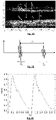
- There figure 2B schematizes the echoes.
- the ordinate axis corresponding to the amplitude of the detected wave and the abscissa axis corresponds to time.
- the time shift dt between the two echoes E p and E d makes it possible to estimate the diameter of the artery, knowing the speed of propagation of the acoustic wave.
- the measurements shown on the figure 2B schematize an acoustic signal sent by each transducer 11 to the selection unit 21.
- Fig. 2C represents a temporal evolution of the diameter D(t) of the artery (ordinate axis - units ⁇ m) as a function of time t (unit: second).
- the maximum diameter corresponds to the systole, while the minimum diameter corresponds to the diastole.
- the variation in diameter ⁇ D between systole and diastole is of the order of 0.6 mm.
- the position of the transducer 11 relative to the artery has an influence on the quality of the measurement of D(t). Simulations have shown that when the transducer is not centered with respect to the artery, the intensity of the reflected acoustic wave decreases. Taking into account the measurement noise, this increases the uncertainty in the determination of the time interval dt, and therefore of the time evolution D(t).
- D(t) There 2D figure shows a simulation configuration.
- An acoustic probe was simulated comprising a line of 25 transducers 11, each operating in emitter/detector mode, placed in contact with a skin S, of cylindrical shape, and of radius approximately 13 mm.
- the artery A has been modeled at the center of the cylinder modeling the skin S.
- the artery A is located at a depth comprised between 10 mm and 15 mm under the skin S, which corresponds to a usual artery depth.
- the intensity of the echoes produced by each transducer in response to an incident acoustic pulse was evaluated.
- the densities and velocities of acoustic propagation in the modeled media S, M and A are representative of those of blood, muscles and skin respectively.
- There figure 2E represents the evolution of the amplitude of the signal (axis of ordinates - arbitrary units) according to the transducer (axis of abscissas).
- the transducers 1, 13 and 25 correspond respectively to the extreme left, centered and extreme right positions of the probe. It is observed that a centered position of the acoustic transducer, with respect to the artery, makes it possible to obtain a maximum echo intensity. Thus, the position of the transducer has a significant influence on the quality of the measurement performed.
- the acoustic selection unit 21 allows selection of the transducer acoustic generating the echoes whose signal is maximum among the other transducers. This results in a precise estimation of the temporal evolution D(t) of the diameter D of the artery.
- the selection unit makes it possible to select a reference transducer, then to estimate a temporal phase shift between the various transducers with respect to the reference transducer.
- the figures 3A and 3B illustrate how the optical modality works.
- a light source 15 and a photodetector 18 have been shown forming a light source-photodetector pair.
- the light source 15 emits an incident light beam 16 propagating, through the skin, towards the artery A of the user.
- the direction of emission is generally perpendicular to the skin.
- the light beam is preferably emitted in a narrow emission spectral band, preferably ⁇ 50 nm, in a spectral range between 500 nm and 1200 nm, and preferably between 500 nm and 1000 nm. This spectral range corresponds to a significant absorption of light by hemoglobin.
- the spectral bands can be centered on the following wavelengths: 525 nm, 660 nm, 740 nm, 805 nm, 850 nm.
- Each light source can be an LED (light-emitting diode), or one end of an optical fiber, the other end of which is placed facing a light source.
- Each photodetector can be a photodiode, or a light end of an optical fiber, the other end of which is connected to a light sensor.
- each light source can be a laser diode, a VECSEL or the end of a light guide, for example an optical fiber.
- the photons of the incident light beam 16 penetrate the user's body. They propagate in the tissues between the skin and the artery A, the latter being located at a depth, under the skin, of the order of 10 mm. Part of the incident photons is backscattered in a direction parallel to the emission direction. The backscattered photons constitute backscattered radiation 17.
- the backscattered radiation 17 can be detected by the photodetector 18, placed facing the skin of the user.
- the distance d between the light source and the photodetector called the backscatter distance, is generally non-zero and is generally between 5 mm and a few cm.
- the photodetector 18 thus makes it possible to measure the intensity of the backscattered radiation according to the backscattering distance d.
- the dotted curved arrows represent optical paths of emitted photons by the light source 15 and detected by the photodetector 18.
- the photodetector is thus arranged to measure an intensity of a beam of light formed by backscattered photons.
- the intensity of the backscattered radiation depends on the variation in blood volume in the artery. The greater the quantity of blood, the greater the quantity of photons absorbed by the hemoglobin, and the more the intensity of the backscattered radiation decreases. With each heartbeat, the blood flow causes, in the probed tissues, a modulation of the absorption of the light propagating in the tissues. This results in a modulation of the intensity of the backscattered radiation detected by the photodetector 18 associated with the light source.
- the signal detected by the photodetector 18 comprises a continuous component, to which is added a pulsatile component, the latter varying according to cardiac activity.
- the intensity detected by the photodetector thus comprises a periodic component, the fundamental frequency of which corresponds to the heart rate.
- each signal corresponds to the opposite of the detected signal: thus, each SO 1 , SO 2 signal is representative of the periodic absorption of the tissues at the measurement points P 1 and P 2 .
- time lag can be estimated from the time difference ⁇ t between remarkable points of each curve, for example maxima or minima.
- the separation distance d(P 1, P 2 ) is greater than 5 mm. It is preferably less than 10 cm or 5 cm.
- the frequency of acquisition of the signals resulting from each photodetector can be between 100 Hz and 100 kHz, which allows an estimation of the pulse wave velocity with sufficient temporal resolution.
- the depth of the artery under the skin is not precisely known.
- the position of the artery, parallel to the support 10, is not known, or may vary according to the movements of the user.
- the backscatter distance must be sufficient to allow propagation of the detected photons through the artery or a volume of tissue impacted by the perturbation of blood volume induced by cardiac activity.
- the source and the photodetector of the same pair it is also preferable for the source and the photodetector of the same pair to be arranged either along the artery, or on either side of the artery, so that the measurement point, located between the source and the photodetector is located close to the artery.
- the optical selection unit 22 takes into account various detected signals as represented on the Figure 3B . These are optical signals representative of the intensity detected by the photodetectors of different light source-photodetector pairs.
- the signals detected include a so-called pulsatile component, which can be considered as periodic, due to the repetition of the cardiac cycles.
- the selection of the relevant source-photodetector pairs is carried out by taking into account an optical selection criterion and by determining two light source-photodetector pairs for which the optical selection criterion is satisfied.
- the optical selection criterion can be a temporal correlation. Indeed, the most relevant detected signals have a comparable temporal evolution, which corresponds to cardiac activity. Selecting detected signals with a high time correlation makes it easier to determine the time offset ⁇ t shown in Fig. Figure 3B .
- temporal correlation is meant a correlation to within a time lag which corresponds to the distance between the measurement points along the artery.
- optical selection criteria can be applied in addition to or replacing the correlation criterion.
- the pulsatile component of each detected signal describes an oscillation of a certain amplitude Amp.
- the acceptance criterion can be an amplitude greater than a certain threshold, or situated in a previously defined acceptance range.
- the optical selection criterion can be a correlation of the temporal evolution of each detected signal, during a period, with a predetermined shape. Two light source-photodetector pairs having the best correlation with a predetermined temporal shape are then selected.
- Another optical selection criterion may be a minimum distance between the source and the photodetector forming a light source-photodetector pair, so that the depth addressed is sufficient.
- optical selection criteria previously described can be combined.
- the optical processing unit 32 then estimates the pulse wave velocity from the optical signals generated by the photodetectors of the selected light source-photodetector pairs.
- the device comprises a calculation unit 35, configured to estimate an arterial pressure value from the temporal evolution of diameter D(t) resulting from the acoustic processing unit 31 and from the VOP resulting from the processing unit optical 32.
- the arterial pressure P(t) obtained by equation (3) describes a periodic function, each period corresponding to one heartbeat. During each period, the maximum pressure corresponds to the systolic blood pressure, the minimum pressure corresponds to the diastolic blood pressure. Mean arterial pressure is the average of the pressure over a period.
- the previously mentioned function f can be determined by calibration, in the presence of a reference measurement of the user's arterial pressure. It is then possible to establish a link between the values measured (D, VOP) at different instants with a reference arterial pressure measured by the reference method. The confrontation between the measured values and the measured reference pressure makes it possible to establish the calibration function.
- FIG 4 represents another example of a device suitable for implementing the invention. It has been indicated on the figure 4 , the main dimensions.
- the device allows the analysis of an artery A extending between the two extreme positions represented A sup and A inf represented on the figure 4 .
- the two groups G 1 and G 2 have been represented by a brace, in which the two light source-photodetector pairs are to be identified according to the position of the artery with respect to the support 10.
- the support 10 is divided into two elementary supports spaced from each other.
- the first elementary support comprises a first group G 1 of photodetectors and light source.
- a second elementary support includes a second group of photodetectors and light sources.
- the transducers can be fixed on one of the elementary supports or on the two elementary supports.
- the support 10 may not be monolithic and comprise different elementary supports.
- the acoustic or optical selection units, as well as the central unit, can form a single unit, implemented by a microprocessor. Alternatively, each of these units implements a microprocessor. According to one possibility, all or part of the selection units or of the central unit is remote, at a distance from the support 10.
- the device comprises a transmission unit so as to transmit the signals coming from the transducers and the photodetectors by wire connection or without thread.
- Step 100 arrangement of the support on the skin of a user, facing an artery.
- Step 110 emission of an acoustic wave by an acoustic emitter and detection of an acoustic wave reflected by an acoustic detector, step 110 being repeated for different acoustic emitters and/or different acoustic detectors.
- Each acoustic signal detected is capable of comprising echoes representative of the reflection, by the artery, of the acoustic wave emitted by the acoustic transmitter.
- Step 120 processing of the acoustic signals by the acoustic selection unit, so as to identify the relevant emitter/acoustic detector pair.
- the latter corresponds to the detector whose detected acoustic signal, following the emission of an acoustic wave by the acoustic emitter, most satisfies the previously mentioned acoustic selection criterion.
- Step 130 acquisition of optical signals by the different photodetectors of different light source-photodetector pairs.
- a light source can be activated sequentially and optical signals from various photodetectors considered to be sufficiently close to the source are acquired to detect usable backscattered radiation.
- the light sources are activated successively.
- Optical signals are then obtained for each light source/photodetector pair.
- Step 140 Processing of the optical signals resulting from each photodetector, during step 130 by the optical selection unit, so as to identify the two relevant light source-photodetector pairs.
- the latter correspond to the pairs whose signals, resulting from the photodetector, best satisfy the optical selection criterion.
- Steps 110 to 140 correspond to a calibration phase, on the basis of the calibration measurements acquired during steps 110 and 130.
- the acquisition of the calibration measurements can be carried out during a predefined calibration period, which can last a few minutes for example .
- Steps 150 to 170 correspond to the implementation of the device, following the calibration phase.
- Step 150 determination of the temporal evolution of the diameter D(t) of the artery, by implementing the acoustic modality.
- the acoustic processing unit 31 receives the acoustic signal resulting from the acoustic detector selected during step 120.
- Step 160 determination of the evolution of the pulse wave velocity VOP of the artery, by implementing the optical modality.
- the optical processing unit 32 receives the optical signals resulting from the respective photodetectors of the two light source-photodetector pairs selected during step 140.
- Steps 150 and 160 can be performed simultaneously or in any order.
- Step 170 estimation of the arterial pressure as a function of the diameter of the artery D(t) and of the PWV resulting from the steps 150 and 160, for example by using the expression (3) or another calibration function
- Steps 150 to 170 can be repeated at successive measurement instants, so as to perform a “continuous” blood pressure measurement, that is to say at sufficiently close instants.
- the calibration phase (steps 110 to 140) can be repeated periodically, so as to identify the most relevant acoustic transducers and light source/photodetector pairs.
- the calibration phase can also be carried out in the event of the occurrence of an arterial pressure measurement considered to be abnormal.
- the invention takes advantage of the fact that the device allows an arterial pressure to be estimated without resorting to compression of a member of the user. It is robust to positioning uncertainties of the support of the device on the skin of the user, as well as to possible movements of the user wearing the support.
Landscapes
- Health & Medical Sciences (AREA)
- Life Sciences & Earth Sciences (AREA)
- Engineering & Computer Science (AREA)
- Veterinary Medicine (AREA)
- Physics & Mathematics (AREA)
- Biophysics (AREA)
- Pathology (AREA)
- Public Health (AREA)
- Biomedical Technology (AREA)
- Heart & Thoracic Surgery (AREA)
- Medical Informatics (AREA)
- Molecular Biology (AREA)
- Surgery (AREA)
- Animal Behavior & Ethology (AREA)
- General Health & Medical Sciences (AREA)
- Cardiology (AREA)
- Nuclear Medicine, Radiotherapy & Molecular Imaging (AREA)
- Radiology & Medical Imaging (AREA)
- Physiology (AREA)
- Vascular Medicine (AREA)
- Computer Vision & Pattern Recognition (AREA)
- Hematology (AREA)
- Dentistry (AREA)
- Oral & Maxillofacial Surgery (AREA)
- Measuring Pulse, Heart Rate, Blood Pressure Or Blood Flow (AREA)
Abstract
Dispositif (1) pour estimer une pression artérielle d'un utilisateur, par une combinaison d'une modalité acoustique, mettant en œuvre des émetteurs et détecteurs acoustiques, et d'une modalité optique, mettant en œuvre des sources de lumière (15) et des photodétecteurs (18), formant des couples source-détecteur. Le dispositif comporte une unité de sélection acoustique (21), configurée pour déterminer le couple émetteur acoustique / détecteur acoustique pertinents, ainsi qu'une unité de sélection optique (22), configurée pour déterminer les couples source de lumière-photodétecteur pertinents. figure 1.Device (1) for estimating a user's blood pressure, by a combination of an acoustic modality, implementing acoustic emitters and detectors, and an optical modality, implementing light sources (15) and photodetectors (18), forming source-detector pairs. The device comprises an acoustic selection unit (21), configured to determine the relevant acoustic emitter/acoustic detector pair, as well as an optical selection unit (22), configured to determine the relevant light source-photodetector pairs. figure 1.
Description
Le domaine technique est la caractérisation de la pression artérielle sans compression.The technical field is the characterization of blood pressure without compression.
La plupart des dispositifs permettant de caractériser la pression artérielle utilisent un capteur de pression couplé à un brassard de compression disposé sur un membre, généralement un bras. La caractérisation de la pression artérielle est effectuée en mesurant la pression exercée par le brassard en un ou plusieurs instants caractéristiques. Le capteur de pression ou le capteur acoustique sont sensibles aux battements cardiaques et à leur amplitude.Most devices for characterizing arterial pressure use a pressure sensor coupled to a compression cuff placed on a limb, generally an arm. The characterization of blood pressure is carried out by measuring the pressure exerted by the cuff at one or more characteristic instants. The pressure sensor or the acoustic sensor are sensitive to heartbeats and their amplitude.
Les dispositifs utilisés par le personnel médical (méthode auscultatoire) sont composés d'un brassard dont la pression est contrôlée et lue par le médecin, associé généralement à un stéthoscope. Lorsque le brassard se dégonfle, on détecte l'apparition et la disparition de sons, appelés sons de Korotkoff. La pression appliquée par le brassard lors de l'apparition et la disparition des sons correspond respectivement à la pression systolique et à la pression diastolique.The devices used by medical personnel (auscultatory method) consist of a cuff whose pressure is controlled and read by the doctor, generally combined with a stethoscope. When the cuff deflates, the appearance and disappearance of sounds, called Korotkoff sounds, are detected. The pressure applied by the cuff during the appearance and disappearance of sounds corresponds respectively to the systolic pressure and the diastolic pressure.
Dans les tensiomètres grand public, un capteur de pression détermine la pression d'air dans le brassard. La compression du brassard est effectuée de manière à obtenir au préalable une occlusion artérielle. Lors de la déflation du brassard, des oscillations de pression apparaissent. Les oscillations augmentent jusqu'à atteindre, transitoirement, une amplitude maximale. A cet instant la pression dans le brassard est considérée égale à la pression artérielle moyenne. A partir de l'amplitude maximale détectée, les pressions artérielles systolique et diastolique sont estimées sur la base de lois empiriques.In consumer blood pressure monitors, a pressure sensor determines the air pressure in the cuff. The compression of the cuff is carried out in such a way as to obtain an arterial occlusion beforehand. During deflation of the cuff, pressure oscillations appear. The oscillations increase until they temporarily reach a maximum amplitude. At this moment the pressure in the cuff is considered equal to the mean arterial pressure. From the detected maximum amplitude, the systolic and diastolic arterial pressures are estimated based on empirical laws.
Cependant, le recours à un dispositif comportant un brassard suppose des phases de compression régulières si l'on souhaite effectuer une mesure de la pression en continu. Cela constitue une source d'inconfort, liée à la fois à la perception de la compression et au bruit de la pompe activant la compression du brassard. En outre, une occlusion répétée selon une fréquence trop importante peut présenter un risque.However, the use of a device comprising a cuff presupposes regular compression phases if it is desired to perform a continuous pressure measurement. This constitutes a source of discomfort, linked both to the perception of the compression and to the noise of the pump activating the compression of the cuff. In addition, repeated occlusion too frequently may present a risk.
Récemment, des développements ont été menés, de façon à pouvoir effectuer des mesures de la pression artérielle dites «cuffless » (sans brassard). La publication [1]
Les principes exposés dans la publication [1] peuvent être mis en œuvre pour concevoir un dispositif porté par un utilisateur, et permettant un suivi continu de la pression artérielle, en réduisant la gêne ressentie par l'utilisateur. Cependant les mesures effectuées dans les deux modalités peuvent être affectées par des incertitudes liées au positionnement des composants actifs (sources de lumière, capteurs acoustiques ou optiques), par rapport à l'artère. Ainsi, lorsque le dispositif est appliqué sur le corps d'un utilisateur, les capteurs doivent être correctement disposés précisément par rapport à l'artère de façon que la variation du diamètre et la vitesse d'onde de pouls soient correctement estimés.The principles set out in publication [1] can be implemented to design a device worn by a user, and allowing continuous monitoring of blood pressure, while reducing the discomfort felt by the user. However, the measurements performed in both modalities can be affected by uncertainties related to the positioning of the active components (light sources, acoustic or optical sensors), relative to the artery. Thus, when the device is applied to the body of a user, the sensors must be correctly positioned precisely with respect to the artery so that the variation in diameter and the pulse wave velocity are correctly estimated.
Aussi, le dispositif précédemment décrit suppose un positionnement précis sur la peau de l'utilisateur. Une autre difficulté est liée aux mouvements de l'utilisateur, qui peuvent entraîner une variation de la position des capteurs par rapport à l'artère. L'invention décrite ci-après permet de surmonter ces difficultés.Also, the device described above assumes precise positioning on the skin of the user. Another difficulty is linked to the movements of the user, which can lead to a variation in the position of the sensors relative to the artery. The invention described below makes it possible to overcome these difficulties.
Un premier objet de l'invention est un dispositif d'estimation d'une pression artérielle d'un utilisateur, le dispositif étant destiné à être porté par l'utilisateur, le dispositif comportant :
- un support, destiné à être appliqué contre la peau de l'utilisateur ;
- plusieurs sources de lumière, disposées sur le support, configurées pour émettre une lumière vers la peau de l'utilisateur lorsqu'elles sont activées ;
- plusieurs photodétecteurs, disposés sur le support, distants de chaque source de lumière, configurés pour détecter une lumière émanant de la peau de l'utilisateur suite à une activation d'au moins une source de lumière, chaque photodétecteur formant, avec ladite source de lumière, un couple source-photodétecteur ;
- plusieurs transducteurs acoustiques, comportant au moins :
- un émetteur acoustique, configuré pour émettre une onde acoustique à travers la peau ;
- et un détecteur acoustique, configuré pour détecter une onde acoustique réfléchie dans le corps de l'utilisateur, se propageant à travers la peau ;
- une unité de sélection acoustique, programmée pour :
- prendre en compte un critère de sélection acoustique ;
- sélectionner un émetteur acoustique et un détecteur acoustique parmi les transducteurs acoustique, la sélection étant effectuée en fonction d'un signal acoustique détecté par chaque détecteur acoustique suite à une émission d'une onde acoustique par au moins un émetteur acoustique;
- une unité de sélection optique, configurée pour :
- prendre en compte un critère de sélection optique ;
- sélectionner un premier couple source de lumière - photodétecteur, comportant une première source de lumière et un premier photodétecteur, choisis parmi les sources de lumière et les photodétecteurs, et un deuxième couple source de lumière - photodétecteur, comportant une deuxième source de lumière et un deuxième photodétecteur, choisis parmi les sources de lumière et les photodétecteurs, la sélection étant effectuée en fonction des signaux détectés par le premier photodétecteur et le deuxième photodétecteur suite à une activation de la première source de lumière et de la deuxième source de lumière ;
- une unité centrale, programmée pour estimer une pression artérielle, à partir :
- du signal détecté par un détecteur acoustique;
- des signaux détectés par le premier photodétecteur et le deuxième photodétecteur.
- a support, intended to be applied against the skin of the user;
- a plurality of light sources, disposed on the support, configured to emit light toward the user's skin when activated;
- several photodetectors, arranged on the support, remote from each light source, configured to detect light emanating from the skin of the user following a activation of at least one light source, each photodetector forming, with said light source, a source-photodetector couple;
- several acoustic transducers, comprising at least:
- an acoustic transmitter, configured to emit an acoustic wave through the skin;
- and an acoustic detector, configured to detect an acoustic wave reflected in the body of the user, propagating through the skin;
- an acoustic selection unit, programmed for:
- take into account an acoustic selection criterion;
- selecting an acoustic emitter and an acoustic detector among the acoustic transducers, the selection being made according to an acoustic signal detected by each acoustic detector following an emission of an acoustic wave by at least one acoustic emitter;
- an optical selection unit, configured for:
- taking into account an optical selection criterion;
- select a first light source - photodetector pair, comprising a first light source and a first photodetector, chosen from among the light sources and the photodetectors, and a second light source - photodetector couple, comprising a second light source and a second photodetector, chosen from among the light sources and the photodetectors, the selection being made according to the signals detected by the first photodetector and the second photodetector following an activation of the first light source and of the second light source;
- a central unit, programmed to estimate arterial pressure, from:
- the signal detected by an acoustic detector;
- signals detected by the first photodetector and the second photodetector.
L'unité centrale peut être programmée pour :
- estimer un diamètre artériel à partir du signal détecté par le détecteur acoustique sélectionné;
- estimer une vitesse d'onde de pouls, à partir des signaux détectés par le premier photodétecteur et le deuxième photodétecteur ;
- estimer la pression artérielle, en fonction du diamètre artériel et de l'onde de pouls estimés.
- estimating an arterial diameter from the signal detected by the selected acoustic detector;
- estimating a pulse wave velocity, from the signals detected by the first photodetector and the second photodetector;
- estimate blood pressure, based on estimated arterial diameter and pulse wave.
De préférence, la source de lumière émet une lumière dans une bande spectrale comprise entre 500 nm et 1200 nm.Preferably, the light source emits light in a spectral band between 500 nm and 1200 nm.
Le dispositif peut comporter :
- un premier groupe de sources de lumière et de photodétecteurs ;
- un deuxième groupe de sources de lumière et de photodétecteurs, distant du premier groupe de sources de lumière et de photodétecteurs.
- a first group of light sources and photodetectors;
- a second group of light sources and photodetectors, remote from the first group of light sources and photodetectors.
L'unité de sélection optique est alors configurée pour :
- sélectionner la première source de lumière et le premier photodétecteur parmi les sources de lumière et les photodétecteurs du premier groupe ;
- sélectionner la deuxième source de lumière et le deuxième photodétecteur parmi les sources de lumière et les photodétecteurs du deuxième groupe.
- selecting the first light source and the first photodetector from among the light sources and the photodetectors of the first group;
- selecting the second light source and the second photodetector from among the light sources and the photodetectors of the second group.
Selon une possibilité, le critère acoustique étant un rapport signal sur bruit, l'unité de sélection acoustique est configurée pour :
- estimer un rapport signal sur bruit de chaque signal détecté par d'un détecteur acoustique ;
- sélectionner le détecteur acoustique pour lequel le rapport signal sur bruit le plus élevé.
- estimer une intensité de chaque signal détecté par un détecteur acoustique ;
- sélectionner le détecteur acoustique dont l'intensité est la plus élevée.
- estimating a signal-to-noise ratio of each signal detected by an acoustic detector;
- select the acoustic detector for which the signal to noise ratio is the highest.
- estimating an intensity of each signal detected by an acoustic detector;
- select the acoustic detector with the highest intensity.
Selon une possibilité, le critère optique étant un critère de corrélation, l'unité de sélection optique est configurée pour :
- estimer une corrélation temporelle entre les signaux détectés en différents instants par des photodétecteurs de chaque couple source de lumière-photodétecteur;
- sélectionner la première source de lumière et le premier photodétecteur ainsi que la deuxième source de lumière et le deuxième photodétecteur en fonction de la corrélation temporelle estimée.
- estimating a temporal correlation between the signals detected at different instants by photodetectors of each light source-photodetector pair;
- selecting the first light source and the first photodetector and the second light source and the second photodetector according to the estimated temporal correlation.
Selon une possibilité, le critère optique est un critère d'amplitude, l'unité de sélection optique est configurée pour :
- estimer une amplitude d'une évolution temporelle de signaux détectés en plusieurs instants par des photodétecteurs de chaque couple source de lumière-photodétecteur;
- sélectionner la première source de lumière et le premier photodétecteur ainsi que la deuxième source de lumière et le deuxième photodétecteur en fonction de l'amplitude.
- estimating an amplitude of a temporal evolution of signals detected over several instants by photodetectors of each light source-photodetector pair;
- selecting the first light source and the first photodetector and the second light source and the second photodetector according to the amplitude.
Selon une possibilité, le critère optique est un critère de forme. L'unité de sélection optique est configurée pour :
- prendre en compte une forme temporelle prédéterminée ;
- déterminer une évolution temporelle des signaux détectés, en différents instants par les photodétecteurs de chaque couple source de lumière-photodétecteur;
- sélectionner la première source de lumière et le premier photodétecteur ainsi que la deuxième source de lumière et le deuxième photodétecteur en fonction d'une corrélation entre l'évolution temporelle des signaux détectés et la forme temporelle prédéterminée.
- a) disposition du support sur la peau d'un utilisateur, face à une artère;
- b) émission d'au moins une onde acoustique incidente par un émetteur acoustique et acquisition de signaux acoustiques par un détecteur acoustique, chaque signal acoustique détecté comportant des échos représentatifs de réflexions de l'onde acoustique incidente par l'artère, l'étape b) étant réalisée pour différents émetteurs acoustique et/ou différents détecteurs acoustiques, de telle sorte que chaque signal acoustique détecté est associé à un émetteur acoustique et à un détecteur acoustique ;
- c) à l'aide de l'unité de sélection acoustique :
- prise en compte d'un critère de sélection acoustique ;
- sélection d'un émetteur acoustique et d'un détecteur acoustique, en fonction d'une confrontation entre chaque signal acoustique détecté, lors de l'étape b), et le critère de sélection acoustique ;
- d) pour chaque source de lumière, émission d'une lumière incidente vers la peau de l'utilisateur et détection d'un rayonnement rétrodiffusé par au moins un photodétecteur, chaque photodétecteur générant un signal optique représentatif de l'intensité du rayonnement rétrodiffusé ;
- e) à l'aide de l'unité de sélection optique :
- prise en compte d'un critère de sélection optique ;
- sélection de deux couples source de lumière - photodétecteur, chaque couple comportant une source de lumière et un photodétecteur, en fonction d'une confrontation entre chaque signal optique issu de chaque photodétecteur et du critère de sélection optique ;
- f) émission d'une onde acoustique incidente par le transducteur acoustique sélectionné lors de c), et formation d'un signal acoustique représentatif d'échos suite à des réflexions de l'onde acoustique incidente par l'artère ;
- g) activation des sources de lumière de chaque couple source de lumière-photodétecteur sélectionné lors de e) et formation, par chaque photodétecteur de chaque couple, d'un signal optique représentatif de l'intensité du rayonnement rétrodiffusé par l'artère ;
- h) en fonction du signal acoustique, et des signaux optiques formés par chaque photodétecteur en différents instants, estimation de la pression artérielle de l'utilisateur.
- h1) en fonction du signal acoustique formé, estimation du diamètre de l'artère;
- h2) en fonction des signaux optiques formés, en différents instants, par chaque photodétecteur sélectionné, estimation d'une vitesse d'onde de pouls ;
- h3) à partir du diamètre de l'artère résultant de la sous-étape h1) et de la vitesse d'onde de pouls résultant de la sous-étape h2), estimation d'une pression artérielle de l'utilisateur.
- take into account a predetermined temporal shape;
- determining a temporal evolution of the signals detected, at different times by the photodetectors of each light source-photodetector pair;
- selecting the first light source and the first photodetector as well as the second light source and the second photodetector according to a correlation between the time evolution of the detected signals and the predetermined time shape.
- a) arrangement of the support on the skin of a user, facing an artery;
- b) emission of at least one incident acoustic wave by an acoustic transmitter and acquisition of acoustic signals by an acoustic detector, each detected acoustic signal comprising echoes representative of reflections of the incident acoustic wave by the artery, step b ) being made for different acoustic emitters and/or different acoustic detectors, such that each detected acoustic signal is associated with an acoustic emitter and an acoustic detector;
- c) using the acoustic selection unit:
- consideration of an acoustic selection criterion;
- selection of an acoustic transmitter and of an acoustic detector, as a function of a comparison between each acoustic signal detected, during step b), and the acoustic selection criterion;
- d) for each light source, emission of incident light towards the skin of the user and detection of backscattered radiation by at least one photodetector, each photodetector generating an optical signal representative of the intensity of the backscattered radiation;
- e) using the optical selection unit:
- consideration of an optical selection criterion;
- selection of two light source/photodetector pairs, each pair comprising a light source and a photodetector, as a function of a comparison between each optical signal coming from each photodetector and the optical selection criterion;
- f) emission of an incident acoustic wave by the acoustic transducer selected during c), and formation of an acoustic signal representative of echoes following reflections of the incident acoustic wave by the artery;
- g) activation of the light sources of each light source-photodetector pair selected in e) and formation, by each photodetector of each pair, of an optical signal representative of the intensity of the radiation backscattered by the artery;
- h) as a function of the acoustic signal, and of the optical signals formed by each photodetector at different instants, estimation of the blood pressure of the user.
- h1) as a function of the acoustic signal formed, estimation of the diameter of the artery;
- h2) as a function of the optical signals formed, at different instants, by each selected photodetector, estimation of a pulse wave velocity;
- h3) from the diameter of the artery resulting from sub-step h1) and the pulse wave velocity resulting from sub-step h2), estimation of a user's blood pressure.
La sous-étape h2) peut comporter une estimation d'un décalage temporel entre les signaux optiques respectivement formés par le premier photodétecteur et le deuxième photodétecteur. Les étapes a) à e) peuvent constituent une phase de calibration du dispositif, les étapes f) à h) étant réitérées entre deux calibrations successives.Sub-step h2) may comprise an estimation of a time shift between the optical signals respectively formed by the first photodetector and the second photodetector. Steps a) to e) may constitute a device calibration phase, steps f) to h) being repeated between two successive calibrations.
Selon une possibilité, le dispositif comporte :
- un premier groupe de sources de lumière et de photodétecteurs ;
- un deuxième groupe de sources de lumière et de photodétecteurs, distant du premier groupe de sources de lumière et de photodétecteurs.
- a first group of light sources and photodetectors;
- a second group of light sources and photodetectors, remote from the first group of light sources and photodetectors.
Le procédé peut alors comporter :
- une sélection d'un premier couple source de lumière/photodétecteur dans le premier groupe;
- une sélection d'un deuxième couple source de lumière/photodétecteur dans le deuxième groupe.
- a selection of a first light source/photodetector pair from the first group;
- a selection of a second light source/photodetector pair from the second group.
Selon un mode de réalisation, le procédé comporte :
- une prise en compte d'une plage de validité de la pression artérielle ;
- lorsque la pression artérielle résultant de l'étape h) est située en dehors de la plage de validité, renouvellement de la phase de calibration.
- taking into account a range of validity of the arterial pressure;
- when the arterial pressure resulting from step h) is situated outside the range of validity, renewal of the calibration phase.
Selon une possibilité, le critère de sélection acoustique est un rapport signal sur bruit maximal, ou une intensité maximale d'un signal acoustique détecté, la sélection de l'émetteur et du détecteur acoustique étant effectuée en fonction du signal acoustique, associé au couple émetteur acoustique/détecteur acoustique, dont le rapport signal sur bruit est maximal ou dont l'intensité est maximale.According to one possibility, the acoustic selection criterion is a maximum signal-to-noise ratio, or a maximum intensity of a detected acoustic signal, the selection of the emitter and of the acoustic detector being carried out as a function of the acoustic signal, associated with the emitter pair acoustic/acoustic detector, whose signal-to-noise ratio is maximum or whose intensity is maximum.
Le critère de sélection optique peut comporter un critère de corrélation temporelle, à un décalage temporel près, de telle sorte que la sélection de chaque couple source-détecteur comporte :
- une estimation d'une corrélation temporelle entre les signaux détectés en différents instants par les photodétecteurs de chaque couple source de lumière-photodétecteur;
- une détermination des couples source de lumière-photodétecteur pour lesquels le signal résultant du photodétecteur présente la corrélation temporelle la plus élevée.
- an estimation of a temporal correlation between the signals detected at different instants by the photodetectors of each light source-photodetector pair;
- a determination of the light source-photodetector pairs for which the signal resulting from the photodetector exhibits the highest temporal correlation.
Le critère de sélection optique peut être un des critères de sélection décrits en lien avec le premier objet de l'invention.The optical selection criterion can be one of the selection criteria described in connection with the first object of the invention.
Le procédé peut être tel que :
- le premier couple source de lumière - photodétecteur définit un premier point de mesure;
- le deuxième couple source de lumière - photodétecteur définit un deuxième point de mesure;
- le premier point de mesure et le deuxième point de mesure sont distants l'un de l'autre.
- the first light source-photodetector pair defines a first measurement point;
- the second light source/photodetector pair defines a second measurement point;
- the first measurement point and the second measurement point are distant from each other.
-
La
figure 1 est un exemple de dispositif selon l'invention.Therefigure 1 is an example of a device according to the invention. -
Les
figures 2A à 2E illustrent une mise en œuvre de la modalité acoustique du dispositif.THEfigures 2A to 2E illustrate an implementation of the acoustic modality of the device. -
Les
figures 3A et 3B illustrent une mise en œuvre de la modalité optique du dispositif.THEfigures 3A and 3B illustrate an implementation of the optical modality of the device. -
La
figure 4 est un autre exemple de dispositif selon l'invention.Therefigure 4 is another example of a device according to the invention. -
La
figure 5 schématise les principales étapes de mise en œuvre d'un procédé de détermination d'une pression artérielle d'un utilisateur à l'aide d'un dispositif tel que décrit en lien avec lafigure 1 ou lafigure 4 .Therefigure 5 schematizes the main implementation steps of a method for determining a user's blood pressure using a device as described in connection with thefigure 1 or thefigure 4 .
La
Le support comporte des composants permettant une mise en œuvre de modalités acoustiques ou optiques telles que décrites dans [1].The support includes components allowing the implementation of acoustic or optical modalities as described in [1].
La modalité acoustique est mise en œuvre à l'aide de transducteurs acoustiques 11, répartis sur le support. Chaque transducteur acoustique est configuré pour émettre et/ou détecter une onde acoustique ultrasonore, de façon à déterminer une évolution temporelle du diamètre D(t) de l'artère A sous l'effet de l'activité cardiaque. Les transducteurs acoustiques peuvent être des transducteurs piézoélectriques ou des capteurs électromécaniques de type MEMS. Les transducteurs acoustiques sont reliés à une unité de traitement acoustique 31. De préférence, mais sans que cela ne soit nécessaire, chaque transducteur acoustique peut à la fois fonctionner en tant qu'émetteur acoustique ou détecteur acoustique.The acoustic modality is implemented using
Le dispositif comporte une unité de traitement acoustique 31, configurée pour recevoir des signaux détectés par au moins un transducteur acoustique 11, fonctionnant en tant que détecteur acoustique, de façon à estimer, en différents instants, le diamètre de l'artère D(t). La modalité acoustique est décrite plus en détail en lien avec les
La modalité optique est mise en œuvre à l'aide de sources de lumière 15 et de photodétecteurs 18, répartis sur le support 10, et distants les uns des autres. Chaque source de lumière est configurée pour émettre une lumière vers la peau de l'utilisateur lorsqu'elle a été activée. Chaque photodétecteur est distant d'une source de lumière. Chaque photodétecteur est configuré pour détecter une lumière émanant de la peau de l'utilisateur suite à une activation d'au moins une source de lumière. Chaque photodétecteur peut ainsi détecter une lumière émise par une source de lumière, et s'étant propagée à travers le corps de l'utilisateur, avant de ressortir de la peau de l'utilisateur, face au photodétecteur. Lorsque les photons détectés par un photodétecteur se sont propagés entre la peau et l'artère, la lumière détectée subit des variations périodiques sous l'effet de la variation périodique du volume sanguin dans les tissus sondés (artère, mais aussi veines, capillaires,...), induite par l'activité cardiaque. La modalité optique est décrite plus en détail en lien avec les
D'une façon générale, la modalité optique suppose la prise en compte de couples source- de lumière -photodétecteur, chaque couple associant une source de lumière et un photodétecteur, distant de la source de lumière. La distance entre une source de lumière et un photodétecteur d'un même couple peut être de l'ordre de quelques millimètres à quelques cm. Un photodétecteur (respectivement une source de lumière) peut former différents couples avec différentes sources de lumière (respectivement différents photodétecteurs).In general, the optical modality assumes the taking into account of source-light-photodetector pairs, each pair associating a light source and a photodetector, remote from the light source. The distance between a light source and a photodetector of the same pair can be of the order of a few millimeters to a few cm. A photodetector (respectively a light source) can form different pairs with different light sources (respectively different photodetectors).
Les photodétecteurs sont reliés à une unité de traitement optique 32. L'unité de traitement optique 32 est configurée pour recevoir des signaux détectés par au moins un photodétecteur 18, de façon à estimer, en différents instants, le délai mis par la perturbation du volume sanguin dans les tissus induite par l'activité cardiaque pour se propager entre deux points de mesure P1, P2 distants d'une distance de séparation Δ, le long d'un segment artériel. Chaque point de mesure est située entre une source de lumière et un photodétecteur. La vitesse d'onde de pouls VOP est estimée à partir d'un ratio entre :
- un décalage temporel Δt entre les signaux respectivement détectés
par chaque photodétecteur 18 ; - la distance de séparation d(P1, P2) entre les deux points de mesure P1 et P2.
- a time lag Δt between the signals respectively detected by each
photodetector 18; - the separation distance d(P 1 , P 2 ) between the two measurement points P 1 and P 2 .
Le support 10 est disposé sur la peau de l'utilisateur, face à l'artère analysée A. Cependant, la position de l'artère par rapport au support 10 n'est pas connue avec précision, en particulier lorsque l'utilisateur est susceptible de bouger. Un aspect important de l'invention est de pouvoir sélectionner :
- un émetteur et un détecteur acoustiques pertinents, c'est-à-dire correctement positionnés par rapport à l'artère A, de façon à obtenir une estimation correcte de la variation temporelle du diamètre de l'artère ;
- deux couples source de lumière-photodétecteur pertinents, chaque couple comportant une source de lumière 15
et un photodétecteur 18, chaque couple étant positionné de façon à déterminer une variation du volume sanguin aux deux points de mesure P1 et P2. La comparaison des signaux issus de chaque photodétecteur permet une estimation de la vitesse de l'onde de pouls.
- a relevant acoustic transmitter and detector, that is to say correctly positioned with respect to the artery A, so as to obtain a correct estimate of the temporal variation of the diameter of the artery;
- two relevant light source-photodetector pairs, each pair comprising a
light source 15 and aphotodetector 18, each pair being positioned so as to determine a variation in the blood volume at the two measurement points P 1 and P 2 . The comparison of the signals coming from each photodetector allows an estimation of the speed of the pulse wave.
Le dispositif comporte une unité de sélection acoustique 21, reliée à chaque détecteur acoustique. L'unité de sélection acoustique 21 est programmée pour prendre en compte un critère de sélection acoustique et sélectionner un émetteur acoustique et un détecteur acoustique parmi les transducteurs acoustiques. L'émetteur et le détecteur acoustique sélectionnés sont ceux pour lesquels suite à l'émission d'une onde acoustique par l'émetteur acoustique, le détecteur acoustique détecte un signal acoustique considéré comme satisfaisant le plus au critère de sélection acoustique. Le critère de sélection acoustique est par exemple un rapport signal sur bruit maximal. Dans ce cas, le détecteur acoustique sélectionné par l'unité de sélection acoustique est par exemple celui qui génère, durant une période de mesure, le signal acoustique présentant le rapport signal sur bruit le plus élevé. Sur la
Le dispositif comporte une unité de sélection optique 22, reliée à chaque photodétecteur 18. L'unité de sélection optique 22 est programmée pour prendre en compte un critère de sélection optique et sélectionner deux signaux optiques résultant des photodétecteurs respectifs de deux couples source de lumière-photodétecteur. Les couples sélectionnés sont ceux pour lesquels les photodétecteurs génèrent un signal optique considéré comme satisfaisant le plus au critère de sélection optique. Le critère de sélection optique est par exemple une corrélation entre les signaux respectivement générés par le photodétecteur de chaque couple. Dans ce cas, les couples source de lumière-photodétecteur sélectionnés par l'unité de sélection optique 22 sont ceux générant des signaux optiques temporellement corrélés, au décalage temporel près. Par temporellement corrélé, on entend que les évolutions, en fonction du temps, des signaux respectivement aux deux points de mesure, sont corrélées. Le décalage temporel dépend de la distance entre les points de mesure respectivement définis par chaque couple source de lumière - photodétecteur. Sur la
- une double flèche matérialisant une première distance, dite de rétrodiffusion, d1 entre la source et le photodétecteur du premier couple source de lumière-photodétecteur sélectionné ;
- une double flèche matérialisant une deuxième distance de rétrodiffusion d2 entre la source et le photodétecteur du deuxième couple source de lumière-photodétecteur sélectionné.
- a double arrow materializing a first distance, called backscatter distance, d 1 between the source and the photodetector of the first selected light source-photodetector pair;
- a double arrow materializing a second backscattering distance d 2 between the source and the photodetector of the second light source-photodetector pair selected.
De préférence, chaque couple source de lumière-photodétecteur sélectionné s'étend de part et d'autre de l'artère, ou le long de l'artère.Preferably, each selected light source-photodetector pair extends on either side of the artery, or along the artery.
Les points de mesure P1 et P2 respectivement formés par les deux couples source de lumière - photodétecteur sélectionnés sont espacés l'un de l'autre. La distance d(P1, P2), le long de l'artère, entre les deux points de mesure, est de préférence supérieure à 1 cm ou à 5 cm.The measurement points P 1 and P 2 respectively formed by the two selected light source/photodetector pairs are spaced apart. The distance d(P 1 , P 2 ), along the artery, between the two measurement points, is preferably greater than 1 cm or 5 cm.
Les signaux résultant des photodétecteurs de chaque couple source de lumière-photodétecteur sélectionné sont adressés à l'unité de traitement optique 32, de façon à estimer la vitesse d'onde de pouls VOP.The signals resulting from the photodetectors of each light source-photodetector pair selected are sent to the
De préférence, les sources de lumière 15 et les photodétecteurs 18 sont répartis sur le support 10 en formant un premier groupe G1 et un deuxième groupe G2. L'unité de sélection optique 22 est programmée pour sélectionner :
- un premier couple source de lumière-photodétecteur parmi les sources de lumière 15 et photodétecteurs 18 du premier groupe G1;
- un deuxième couple source de lumière-photodétecteur parmi les sources de lumière 15 et photodétecteurs 18 du deuxième groupe G2.
- a first light source-photodetector pair from among the
light sources 15 andphotodetectors 18 of the first group G1; - a second light source-photodetector pair from among the
light sources 15 andphotodetectors 18 of the second group G 2 .
Cette répartition selon deux groupes permet de garantir une distance de séparation minimale d(P1, P2)min entre les premier et deuxième points de mesure P1, P2 respectivement définis par chaque couple source de lumière-photodétecteur sélectionné. La distance d(P1,P2) entre les points de mesure P1 et P2 est supposée connue par la connaissance de la géométrie du dispositif. Elle est représentée sur la
Les
Les mesures schématisées sur la
La position du transducteur 11 par rapport à l'artère a une influence sur la qualité de la mesure de D(t). Des simulations ont montré que lorsque le transducteur n'est pas centré par rapport à l'artère, l'intensité de l'onde acoustique réfléchie diminue. Compte tenu du bruit de mesure, cela augmente l'incertitude dans la détermination de l'intervalle temporel dt, et donc de l'évolution temporelle D(t). La
Selon une possibilité, plusieurs transducteurs, déphasés les uns des autres, sont utilisés simultanément. L'unité de sélection permet de sélectionner un transducteur de référence, puis d'estimer un déphasage temporel entre les différents transducteurs par rapport au transducteur de référence.According to one possibility, several transducers, out of phase with each other, are used simultaneously. The selection unit makes it possible to select a reference transducer, then to estimate a temporal phase shift between the various transducers with respect to the reference transducer.
Les
Chaque source de lumière peut être une LED (diode électroluminescente), ou une extrémité d'une fibre optique, dont l'autre extrémité est disposée face à une source lumineuse. Chaque photodétecteur peut être une photodiode, ou une extrémité lumineuse d'une fibre optique, dont l'autre extrémité est reliée à un capteur de lumière. De façon alternative, chaque source de lumière peut être une diode laser, un VECSEL ou l'extrémité d'un guide de lumière, par exemple une fibre optique.Each light source can be an LED (light-emitting diode), or one end of an optical fiber, the other end of which is placed facing a light source. Each photodetector can be a photodiode, or a light end of an optical fiber, the other end of which is connected to a light sensor. Alternatively, each light source can be a laser diode, a VECSEL or the end of a light guide, for example an optical fiber.
Les photons du faisceau lumineux incident 16 pénètrent dans le corps de l'utilisateur. Ils se propagent dans les tissus entre la peau et l'artère A, cette dernière étant située à une profondeur, sous la peau, de l'ordre de 10 mm. Une partie des photons incidents est rétrodiffusée selon une direction parallèle à la direction d'émission. Les photons rétrodiffusés constituent un rayonnement rétrodiffusé 17. Le rayonnement rétrodiffusé 17 peut être détecté par le photodétecteur 18, placé en regard de la peau de l'utilisateur. La distance d entre la source de lumière et le photodétecteur, dite distance de rétrodiffusion, est généralement non nulle et est généralement comprise entre 5 mm et quelques cm . Le photodétecteur 18 permet ainsi de mesurer l'intensité du rayonnement rétrodiffusé selon la distance de rétrodiffusion d. Sur la
Plus la distance de rétrodiffusion est élevée, plus les photons constituant le rayonnement rétrodiffusé 17 pénètrent les tissus de l'utilisateur selon une profondeur élevée. L'intensité du rayonnement rétrodiffusé dépend de la variation de volume sanguin dans l'artère. Plus la quantité de sang est importante, plus la quantité de photons absorbés par l'hémoglobine est importante, et plus l'intensité du rayonnement rétrodiffusé diminue. A chaque battement cardiaque, l'afflux sanguin entraîne, dans les tissus sondés, une modulation de l'absorption de la lumière se propageant dans les tissus. Il en résulte une modulation de l'intensité du rayonnement rétrodiffusé détecté par le photodétecteur 18 associé à la source de lumière.The greater the backscatter distance, the greater the depth of the photons constituting the backscattered
Le signal détecté par le photodétecteur 18 comporte une composante continue, à laquelle s'ajoute une composante pulsatile, cette dernière variant en fonction de l'activité cardiaque. L'intensité détectée par le photodétecteur comporte ainsi une composante périodique, dont la fréquence fondamentale correspond à la fréquence cardiaque.The signal detected by the
Comme représenté sur la ![]()
![]()
La
- un premier signal optique SO1 résultant du photodétecteur du premier couple source de lumière-photodétecteur ;
- un deuxième signal optique SO2 résultant du photodétecteur du deuxième couple source de lumière-photodétecteur.
- a first optical signal SO 1 resulting from the photodetector of the first light source-photodetector pair;
- a second optical signal SO 2 resulting from the photodetector of the second light source-photodetector pair.
Sur la
De préférence la distance de séparation d(P1, P2) est supérieure à 5 mm . Elle est de préférence inférieure à 10 cm ou 5 cm.Preferably, the separation distance d(P 1, P 2 ) is greater than 5 mm. It is preferably less than 10 cm or 5 cm.
La fréquence d'acquisition des signaux résultant de chaque photodétecteur peut être comprise entre 100 Hz et 100 kHz, ce qui permet une estimation de la vitesse d'onde de pouls avec une résolution temporelle suffisante.The frequency of acquisition of the signals resulting from each photodetector can be between 100 Hz and 100 kHz, which allows an estimation of the pulse wave velocity with sufficient temporal resolution.
Cependant, la profondeur de l'artère sous la peau n'est pas connue avec précision. De même, la position de l'artère, parallèlement au support 10, n'est pas connue, ou peut varier en fonction des mouvements de l'utilisateur. Ainsi, il est difficile de déterminer a priori les couples sourcephotodétecteurs les plus pertinents pour estimer précisément la vitesse d'onde de pouls. On comprend, de la
L'unité de sélection optique 22 prend en compte différents signaux détectés tels que représentés sur la
Le critère de sélection optique peut être une corrélation temporelle. En effet, les signaux détectés les plus pertinents ont une évolution temporelle comparable, qui correspond à l'activité cardiaque. Le fait de sélectionner des signaux détectés ayant une corrélation temporelle élevée facilite la détermination du décalage temporel Δt illustré sur la
D'autres critères de sélection optique peuvent être appliqués en compléments ou en remplacement du critère de corrélation. Au cours de chaque période, la composante pulsatile de chaque signal détecté décrit une oscillation d'une certaine amplitude Amp. Le critère d'acceptation peut être une amplitude supérieure à un certain seuil, ou située dans une plage d'acceptation préalablement définie.Other optical selection criteria can be applied in addition to or replacing the correlation criterion. During each period, the pulsatile component of each detected signal describes an oscillation of a certain amplitude Amp. The acceptance criterion can be an amplitude greater than a certain threshold, or situated in a previously defined acceptance range.
Le critère de sélection optique peut être une corrélation de l'évolution temporelle de chaque signal détecté, au cours d'une période, avec une forme prédéterminée. On sélectionne alors deux couples source de lumière-photodétecteur présentant la meilleure corrélation avec une forme temporelle prédéterminée.The optical selection criterion can be a correlation of the temporal evolution of each detected signal, during a period, with a predetermined shape. Two light source-photodetector pairs having the best correlation with a predetermined temporal shape are then selected.
Un autre critère de sélection optique peut être une distance minimale entre la source et le photodétecteur formant un couple de source de lumière-photodétecteur, de façon que la profondeur adressée soit suffisante.Another optical selection criterion may be a minimum distance between the source and the photodetector forming a light source-photodetector pair, so that the depth addressed is sufficient.
Les critères de sélection optiques précédemment décrits peuvent être combinés.The optical selection criteria previously described can be combined.
L'unité de traitement optique 32 estime ensuite la vitesse d'onde de pouls à partir signaux optiques générés par les photodétecteurs des couples sources de lumière-photo détecteurs sélectionnés.The
Le dispositif comporte une unité de calcul 35, configurée pour estimer une valeur de pression artérielle à partir de l'évolution temporelle de diamètre D(t) résultant de l'unité de traitement acoustique 31 et de la VOP résultant de l'unité de traitement optique 32. La pression artérielle P est telle que ![]()
![]()
Par exemple, la fonction f peut être telle que : ![]()
- P(t) est la pression artérielle à un instant t
- D 0 est un diamètre de référence, par exemple le diamètre en fin de diastole
- P 0 est une pression de référence correspondant à D = D0.
- P ( t ) is the blood pressure at time t
- D 0 is a reference diameter, for example the diameter at the end of diastole
- P 0 is a reference pressure corresponding to D = D 0 .
La pression artérielle P(t) obtenue par l'équation (3) décrit une fonction périodique, chaque période correspondant à un battement cardiaque. Durant chaque période, la pression maximale correspond à la pression artérielle systolique, la pression minimale correspond à la pression artérielle diastolique. La pression artérielle moyenne est la moyenne de la pression sur une période.The arterial pressure P(t) obtained by equation (3) describes a periodic function, each period corresponding to one heartbeat. During each period, the maximum pressure corresponds to the systolic blood pressure, the minimum pressure corresponds to the diastolic blood pressure. Mean arterial pressure is the average of the pressure over a period.
La fonction f précédemment évoquée peut être déterminée par une calibration, en présence d'une mesure de référence de la pression artérielle de l'utilisateur. On peut alors établir un lien entre les valeurs mesurées (D, VOP) en différents instants avec une pression artérielle de référence mesurée par la méthode de référence. La confrontation entre les valeurs mesurées et la pression de référence mesurée permet d'établir la fonction de calibration.The previously mentioned function f can be determined by calibration, in the presence of a reference measurement of the user's arterial pressure. It is then possible to establish a link between the values measured (D, VOP) at different instants with a reference arterial pressure measured by the reference method. The confrontation between the measured values and the measured reference pressure makes it possible to establish the calibration function.
La
Selon une variante, le support 10 est divisé en deux supports élémentaires distants l'un de l'autre. Le premier support élémentaire comporte un premier groupe G1 de photodétecteurs et de source de lumière. Un deuxième support élémentaire comporte un deuxième groupe de photodétecteurs et de sources de lumière. les transducteurs peuvent être fixés sur un des supports élémentaires ou sur les deux supports élémentaires. Ainsi, le support 10 peut ne pas être monolithique et comporter différents supports élémentaires.According to a variant, the
Les unités de sélection acoustique ou optique, ainsi que l'unité centrale, peuvent former une même unité, mise en œuvre par un microprocesseur. De façon alternative, chacune de ces unités met en œuvre un microprocesseur. Selon une possibilité, tout ou partie des unités de sélection ou de l'unité centrale est déportée, à distance du support 10. Le dispositif comporte une unité de transmission de façon à transmettre les signaux issus des transducteurs et des photodétecteurs par liaison filaire ou sans fil.The acoustic or optical selection units, as well as the central unit, can form a single unit, implemented by a microprocessor. Alternatively, each of these units implements a microprocessor. According to one possibility, all or part of the selection units or of the central unit is remote, at a distance from the
La
Etape 100 : disposition du support sur la peau d'un utilisateur, face à une artère.Step 100: arrangement of the support on the skin of a user, facing an artery.
Etape 110 : émission d'une onde acoustique par un émetteur acoustique et détection d'une onde acoustique réfléchie par un détecteur acoustique, l'étape 110 étant répétée pour différents émetteurs acoustiques et/ou différents détecteurs acoustiques. Chaque signal acoustique détecté est susceptible de comporter des échos représentatifs de la réflexion, par l'artère, de l'onde acoustique émise par l'émetteur acoustique.Step 110: emission of an acoustic wave by an acoustic emitter and detection of an acoustic wave reflected by an acoustic detector, step 110 being repeated for different acoustic emitters and/or different acoustic detectors. Each acoustic signal detected is capable of comprising echoes representative of the reflection, by the artery, of the acoustic wave emitted by the acoustic transmitter.
Etape 120 : traitement des signaux acoustiques par l'unité de sélection acoustique, de façon à identifier le couple émetteur / détecteur acoustique pertinent. Ce dernier correspond au détecteur dont le signal acoustique détecté, suite à l'émission d'une onde acoustique par l'émetteur acoustique, satisfait le plus au critère de sélection acoustique précédemment évoqué.Step 120: processing of the acoustic signals by the acoustic selection unit, so as to identify the relevant emitter/acoustic detector pair. The latter corresponds to the detector whose detected acoustic signal, following the emission of an acoustic wave by the acoustic emitter, most satisfies the previously mentioned acoustic selection criterion.
Etape 130 : acquisition de signaux optiques par les différents photodétecteurs de différents couples source de lumière-photodétecteur. Lors de cette étape, on peut activer séquentiellement une source de lumière et on acquiert des signaux optiques issus de différents photodétecteurs considérés comme suffisamment proches de la source pour détecter un rayonnement rétrodiffusé exploitable. Les sources de lumière sont activées successivement. On obtient ensuite des signaux optiques pour chaque couple source de lumière - photodétecteur.Step 130: acquisition of optical signals by the different photodetectors of different light source-photodetector pairs. During this step, a light source can be activated sequentially and optical signals from various photodetectors considered to be sufficiently close to the source are acquired to detect usable backscattered radiation. The light sources are activated successively. Optical signals are then obtained for each light source/photodetector pair.
Etape 140 : Traitement des signaux optiques résultant de chaque photodétecteur, lors de l'étape 130 par l'unité de sélection optique, de façon à identifier les deux couples source de lumière-photodétecteur pertinents. Ces derniers correspondent aux couples dont les signaux, résultant du photodétecteur, satisfont le plus au critère de sélection optique.Step 140: Processing of the optical signals resulting from each photodetector, during
Les étapes 110 à 140 correspondent à une phase de calibration, sur la base des mesures de calibration acquises lors des étapes 110 et 130. L'acquisition des mesures de calibration peut être effectuées durant une période de calibration prédéfinie, pouvant durer quelques minutes par exemple.
Les étapes 150 à 170 correspondent à la mise en œuvre du dispositif, suite à la phase de calibration.
Etape 150 : détermination de l'évolution temporelle du diamètre D(t) de l'artère, en mettant en œuvre la modalité acoustique. Au cours de cette étape, l'unité de traitement acoustique 31 reçoit le signal acoustique résultant du détecteur acoustique sélectionné lors de l'étape 120.Step 150: determination of the temporal evolution of the diameter D(t) of the artery, by implementing the acoustic modality. During this step, the
Etape 160 : détermination de l'évolution la vitesse d'onde de pouls VOP de l'artère, en mettant en œuvre la modalité optique. Au cours de cette étape, l'unité de traitement optique 32 reçoit les signaux optiques résultant des photodétecteurs respectifs des deux couples source de lumière-photodétecteur sélectionnés lors de l'étape 140.Step 160: determination of the evolution of the pulse wave velocity VOP of the artery, by implementing the optical modality. During this step, the
Les étapes 150 et 160 peuvent être effectués simultanément ou dans un ordre quelconque.
Etape 170 : estimation de la pression artérielle en fonction du diamètre de l'artère D(t) et de la VOP résultant des étapes 150 et 160, par exemple en utilisant l'expression (3) ou une autre fonction de calibrationStep 170: estimation of the arterial pressure as a function of the diameter of the artery D(t) and of the PWV resulting from the
Les étapes 150 à 170 peuvent être réitérées à des instants de mesure successifs, de façon à effectuer une mesure de la pression artérielle « en continu », c'est-à-dire à des instants suffisamment rapprochés. La phase de calibration (étapes 110 à 140) peut être réitérée périodiquement, de façon à identifier les transducteurs acoustiques et couples source de lumière/photodétecteur les plus pertinents. La phase de calibration peut également être effectuée en cas de survenue d'une mesure de pression artérielle considérée comme anormale.
L'invention tire profit du fait que le dispositif permet l'estimation d'une pression artérielle sans recours à une compression d'un membre de l'utilisateur. Elle est robuste à des incertitudes de positionnement du support du dispositif sur la peau de l'utilisateur, ainsi qu'à des éventuels mouvements de l'utilisateur portant le support.The invention takes advantage of the fact that the device allows an arterial pressure to be estimated without resorting to compression of a member of the user. It is robust to positioning uncertainties of the support of the device on the skin of the user, as well as to possible movements of the user wearing the support.
Claims (17)
Applications Claiming Priority (1)
| Application Number | Priority Date | Filing Date | Title |
|---|---|---|---|
| FR2110386A FR3127385A1 (en) | 2021-09-30 | 2021-09-30 | Cuffless method of determining a user's blood pressure |
Publications (1)
| Publication Number | Publication Date |
|---|---|
| EP4159118A1 true EP4159118A1 (en) | 2023-04-05 |
Family
ID=79019046
Family Applications (1)
| Application Number | Title | Priority Date | Filing Date |
|---|---|---|---|
| EP22198522.9A Pending EP4159118A1 (en) | 2021-09-30 | 2022-09-28 | Cuff-less method for determining a user's blood pressure |
Country Status (3)
| Country | Link |
|---|---|
| US (1) | US20230095227A1 (en) |
| EP (1) | EP4159118A1 (en) |
| FR (1) | FR3127385A1 (en) |
Citations (2)
| Publication number | Priority date | Publication date | Assignee | Title |
|---|---|---|---|---|
| US20100081912A1 (en) * | 2008-09-30 | 2010-04-01 | Nellcor Puritan Bennett Llc | Ultrasound-Optical Doppler Hemometer and Technique for Using the Same |
| US20180078155A1 (en) * | 2016-09-16 | 2018-03-22 | Qualcomm Incorporated | Multi-model blood pressure estimation |
-
2021
- 2021-09-30 FR FR2110386A patent/FR3127385A1/en active Pending
-
2022
- 2022-09-28 EP EP22198522.9A patent/EP4159118A1/en active Pending
- 2022-09-30 US US17/937,055 patent/US20230095227A1/en active Pending
Patent Citations (2)
| Publication number | Priority date | Publication date | Assignee | Title |
|---|---|---|---|---|
| US20100081912A1 (en) * | 2008-09-30 | 2010-04-01 | Nellcor Puritan Bennett Llc | Ultrasound-Optical Doppler Hemometer and Technique for Using the Same |
| US20180078155A1 (en) * | 2016-09-16 | 2018-03-22 | Qualcomm Incorporated | Multi-model blood pressure estimation |
Non-Patent Citations (2)
| Title |
|---|
| NABEEL M.: "Bi-modal arterial compliance probe for calibration-free cuffless blood pressure estimation", IEEE TRANSACTIONS ON BIOMEDICAL ENGINEERING, vol. 5, no. 11, November 2018 (2018-11-01) |
| NABEEL P M ET AL: "Bi-Modal Arterial Compliance Probe for Calibration-Free Cuffless Blood Pressure Estimation", IEEE TRANSACTIONS ON BIOMEDICAL ENGINEERING, IEEE, USA, vol. 65, no. 11, 1 November 2018 (2018-11-01), pages 2392 - 2404, XP011691969, ISSN: 0018-9294, [retrieved on 20181017], DOI: 10.1109/TBME.2018.2866332 * |
Also Published As
| Publication number | Publication date |
|---|---|
| FR3127385A1 (en) | 2023-03-31 |
| US20230095227A1 (en) | 2023-03-30 |
Similar Documents
| Publication | Publication Date | Title |
|---|---|---|
| EP3413803B1 (en) | Ultrasound devices for estimating blood pressure and other cardiovascular properties | |
| JP3910521B2 (en) | Blood pressure measurement device | |
| JP5884256B2 (en) | Blood pressure measuring device and blood pressure measuring method | |
| US7621876B2 (en) | Continuous, non-invasive technique for determining blood pressure using a transmission line model and transcutaneous ultrasound measurements | |
| US8388544B2 (en) | System and method for measuring blood viscosity | |
| JP2016214736A (en) | Blood pressure measurement device and blood pressure measurement method | |
| JP2006263128A (en) | Method and device for measuring vascular elasticity modulus | |
| JP2017127494A (en) | Blood vessel elasticity index value measuring device, blood pressure measuring device, and blood vessel elasticity index value measuring method | |
| US20220257154A1 (en) | Miniaturized noninvasive glucose sensor and continuous glucose monitoring system | |
| CN112890796B (en) | Pulse wave monitoring device and method based on optical fiber sensing | |
| EP4159118A1 (en) | Cuff-less method for determining a user's blood pressure | |
| Hast et al. | Arterial pulse shape measurement using self-mixing effect in a diode laser | |
| KR20190105421A (en) | apparatus and method for measuring blood presure based on PPG | |
| JP4680411B2 (en) | Arterial blood pressure measuring method and arterial blood pressure measuring device | |
| Hast | Self-mixing interferometry and its applications in noninvasive pulse detection | |
| EP4316363A1 (en) | Device and method for measuring blood pressure | |
| JP4320925B2 (en) | Pulse rate detector | |
| FR3118411A1 (en) | Method for estimating a heart rate or a respiratory rate | |
| EP4266995A1 (en) | Device and method for measuring blood pressure and a state of stress | |
| JP2011167347A (en) | Circulatory organ function measuring apparatus, circulatory organ function measuring method and program | |
| JP7067460B2 (en) | Component concentration measuring device | |
| Hast et al. | Arterial pulse shape measurement using self-mixing inteferometry | |
| EP0534217B1 (en) | Process for ultrasonic measurement of the position of at least one moving interface and means for application of the process | |
| JP2006136483A (en) | Blood pressure measuring apparatus and blood pressure judging method | |
| KR20190102135A (en) | Cardiovascular and Cerebrovascular Disease Risk Assessment System Using Adsorption Cup Type Blood Flow Measurement Sensor |
Legal Events
| Date | Code | Title | Description |
|---|---|---|---|
| PUAI | Public reference made under article 153(3) epc to a published international application that has entered the european phase |
Free format text: ORIGINAL CODE: 0009012 |
|
| STAA | Information on the status of an ep patent application or granted ep patent |
Free format text: STATUS: REQUEST FOR EXAMINATION WAS MADE |
|
| 17P | Request for examination filed |
Effective date: 20220928 |
|
| AK | Designated contracting states |
Kind code of ref document: A1 Designated state(s): AL AT BE BG CH CY CZ DE DK EE ES FI FR GB GR HR HU IE IS IT LI LT LU LV MC MK MT NL NO PL PT RO RS SE SI SK SM TR |