EP4159019A1 - Robotergartenwerkzeugsystem und verfahren für robotergartenwerkzeug - Google Patents
Robotergartenwerkzeugsystem und verfahren für robotergartenwerkzeug Download PDFInfo
- Publication number
- EP4159019A1 EP4159019A1 EP22194950.6A EP22194950A EP4159019A1 EP 4159019 A1 EP4159019 A1 EP 4159019A1 EP 22194950 A EP22194950 A EP 22194950A EP 4159019 A1 EP4159019 A1 EP 4159019A1
- Authority
- EP
- European Patent Office
- Prior art keywords
- robot
- gardening tool
- boundary
- signal
- detection apparatus
- Prior art date
- Legal status (The legal status is an assumption and is not a legal conclusion. Google has not performed a legal analysis and makes no representation as to the accuracy of the status listed.)
- Granted
Links
Images

Classifications
-
- A—HUMAN NECESSITIES
- A01—AGRICULTURE; FORESTRY; ANIMAL HUSBANDRY; HUNTING; TRAPPING; FISHING
- A01D—HARVESTING; MOWING
- A01D34/00—Mowers; Mowing apparatus of harvesters
- A01D34/006—Control or measuring arrangements
- A01D34/008—Control or measuring arrangements for automated or remotely controlled operation
-
- G—PHYSICS
- G05—CONTROLLING; REGULATING
- G05D—SYSTEMS FOR CONTROLLING OR REGULATING NON-ELECTRIC VARIABLES
- G05D1/00—Control of position, course, altitude or attitude of land, water, air or space vehicles, e.g. using automatic pilots
- G05D1/20—Control system inputs
- G05D1/24—Arrangements for determining position or orientation
- G05D1/247—Arrangements for determining position or orientation using signals provided by artificial sources external to the vehicle, e.g. navigation beacons
-
- A—HUMAN NECESSITIES
- A01—AGRICULTURE; FORESTRY; ANIMAL HUSBANDRY; HUNTING; TRAPPING; FISHING
- A01D—HARVESTING; MOWING
- A01D2101/00—Lawn-mowers
-
- G—PHYSICS
- G05—CONTROLLING; REGULATING
- G05D—SYSTEMS FOR CONTROLLING OR REGULATING NON-ELECTRIC VARIABLES
- G05D2107/00—Specific environments of the controlled vehicles
- G05D2107/20—Land use
- G05D2107/23—Gardens or lawns
Definitions
- the present invention relates to the field of gardening tools, in particular to a robot gardening tool system and a method for a robot gardening tool, and more specifically to a grass-cutting robot and a method for controlling same.
- Robot gardening tools are being used ever more widely.
- Robot gardening tools can work by themselves, e.g. cut grass, in a predetermined work area without the need for user intervention. This not only saves manpower but also allows the user to have more free time.
- robot gardening tools are likely to encounter problems in the course of working.
- the physical conditions in the work area might not be ideal, e.g. there might be narrow or restricted areas, or road conditions that the robot gardening tool struggles to overcome.
- These physical conditions will result in the robot gardening tool becoming jammed in the course of working, and thereby being unable to continue to complete the work.
- human intervention might be needed to disengage the tool from its jammed state, before letting it continue to work on its own.
- this requires human participation and prolongs the time needed to complete the work, so is undesirable.
- the present invention provides a robot gardening tool system and a method for a robot gardening tool.
- a robot gardening tool system comprises a robot gardening tool and a boundary module.
- the boundary module delimits a work area and/or a non-work area of the robot gardening tool, and the boundary module comprises at least one boundary element defining a periphery of the work area and/or the non-work area.
- the robot gardening tool comprises a boundary detection apparatus, a jamming detection apparatus and a control apparatus.
- the boundary detection apparatus is configured to detect the at least one boundary element; the jamming detection apparatus communicates with the boundary detection apparatus and is configured to judge whether the robot gardening tool is jammed based on a feedback signal S i of the boundary detection apparatus; and the control apparatus is configured to control the robot gardening tool to perform an extrication operation when the robot gardening tool is jammed.
- the boundary module comprises a signal generating unit, which generates an excitation signal and sends the excitation signal to the at least one boundary element
- the boundary element comprises a boundary line which generates a boundary signal upon receiving the excitation signal, the boundary signal for example being an electromagnetic field.
- At least one boundary comprises a physical boundary such as a fence, wall, etc.
- the boundary detection apparatus comprises a signal receiving module for sensing the boundary signal, and the boundary detection apparatus issues the feedback signal S i when the strength of the boundary signal sensed by the signal receiving module is greater than a strength threshold.
- the boundary detection apparatus comprises a collision sensor such as an accelerometer, and the boundary detection apparatus issues the feedback signal S i when the collision sensor senses that the robot gardening tool has collided with the at least one boundary.
- a collision sensor such as an accelerometer
- the jamming detection apparatus receives the feedback signal S i , records a time of occurrence t i of each feedback signal S i , and calculates a time interval ⁇ t i between two consecutive feedback signals S i and S i+1 , and the jamming detection apparatus is configured to judge whether the robot gardening tool is jammed based on the time interval ⁇ t i .
- the jamming detection apparatus determines that the robot gardening tool is jammed when the time interval ⁇ t i is less than a time threshold.
- the jamming detection apparatus determines that the robot gardening tool is jammed when n consecutive time intervals ⁇ t i , ⁇ t i+1 ... ⁇ t i+n-1 are all less than a time threshold, wherein n is for example selected from one of 2 - 10.
- the jamming detection apparatus determines that the robot gardening tool is jammed when m time intervals of n consecutive time intervals ⁇ t i , ⁇ t i+1 ... ⁇ t i+n-1 are all less than a time threshold, wherein n is for example selected from one of 2 - 10, m is for example selected from one of 2 - 9, and m ⁇ n.
- the robot gardening tool further comprises a trajectory recording apparatus, which records a trajectory of advance of the robot gardening tool, and the extrication operation comprises causing the robot gardening tool to retreat along the recorded trajectory of advance for a predetermined time or a predetermined distance, and preferably then turn aside through a predetermined angle.
- a trajectory recording apparatus which records a trajectory of advance of the robot gardening tool
- the extrication operation comprises causing the robot gardening tool to retreat along the recorded trajectory of advance for a predetermined time or a predetermined distance, and preferably then turn aside through a predetermined angle.
- the extrication operation comprises causing the robot gardening tool to advance along the at least one boundary element for a predetermined time or a predetermined distance, and then turn aside through a predetermined angle.
- the predetermined time is a random time
- the predetermined angle is a random angle.
- control apparatus is configured to issue an alert to a user when jamming of the robot gardening tool is detected again within a period of time after completion of the extrication operation.
- the robot gardening tool is a grass-cutting robot.
- a method for a robot gardening tool comprises: detecting at least one boundary element of a boundary module, the boundary module delimiting a work area and/or a non-work area of the robot gardening tool, and the at least one boundary element defining a periphery of the work area and/or the non-work area; generating a feedback signal S i based on the detection; and judging whether the robot gardening tool is jammed based on the feedback signal S i .
- the method further comprises: controlling the robot gardening tool to perform an extrication operation when the robot gardening tool is jammed.
- the method further comprises: generating an excitation signal and sending the excitation signal to the at least one boundary element, wherein the boundary element comprises a boundary line which generates a boundary signal upon receiving the excitation signal, the boundary signal for example being an electromagnetic field.
- the method further comprises at least one of the following: generating the feedback signal S i when the strength of a boundary signal is greater than a strength threshold; and generating the feedback signal S i when the robot gardening tool collides with at least one boundary.
- the method further comprises: recording a time of occurrence t i of each feedback signal S i ; calculating a time interval ⁇ t i between two consecutive feedback signals S i and S i+1 ; and judging whether the robot gardening tool is jammed based on the time interval ⁇ t i .
- the method further comprises: determining that the robot gardening tool is jammed when the time interval ⁇ t i is less than a time threshold.
- the method further comprises: determining that the robot gardening tool is jammed when n consecutive time intervals ⁇ t i , ⁇ t i+1 ... ⁇ t i+n-1 are all less than a time threshold, wherein n is selected from one of 2 - 10.
- the method further comprises: determining that the robot gardening tool is jammed when m time intervals of n consecutive time intervals ⁇ t i , ⁇ t i+1 ... ⁇ t i+n-1 are all less than a time threshold, wherein n is selected from one of 2 - 10, m is selected from one of 2 - 9, and m ⁇ n.
- the method further comprises: recording a trajectory of advance of the robot gardening tool; and causing the robot gardening tool to retreat along the recorded trajectory of advance for a predetermined time or a predetermined distance, and preferably then turn aside through a predetermined angle, wherein preferably, the predetermined time is a random time, and the predetermined angle is a random angle.
- the method further comprises: issuing an alert to a user when jamming of the robot gardening tool is detected again within a period of time after completion of the extrication operation.
- the robot gardening tool system and method for a robot gardening tool according to one or more embodiments of the present invention have a number of technical advantages.
- the robot gardening tool according to one or more embodiments of the present invention can conveniently detect whether jamming has occurred, and if jamming has occurred, can effectively extricate itself from the jammed state.
- the robot gardening tool according to one or more embodiments of the present invention can avoid misjudgements concerning a jammed state, and can perform more effective operations on work areas where jamming is likely.
- the method for a robot gardening tool according to one or more embodiments of the present invention has a simple, unique and effective design, and is suitable for detecting jamming in various areas where jamming is likely in work areas.
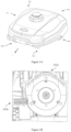
- Figs. 1A - 1C show schematic drawings of a robot gardening tool 100 according to embodiments of the present invention.
- the robot gardening tool 100 may be a gardening tool that is capable of moving physically and performing an operation on a garden in a specific area on its own, without the need for manual intervention.
- the robot gardening tool 100 is for example a grass-cutting robot capable of trimming a lawn.
- the robot gardening tool 100 comprises a housing 101 and at least one operating tool (e.g. a grass-cutting tool) 103a, 103b disposed on the housing 101.
- the robot gardening tool 100 has a first end or front end 100a, a second end or rear end 100b, and a longitudinal axis or axis L extending through the first end 100a and second end 100b.
- the robot gardening tool 100 comprises a travelling apparatus and a motive power apparatus.
- the travelling apparatus is configured to facilitate travel of the robot gardening tool 100 on a physical surface in a specific direction.
- the travelling apparatus comprises front rollers 102a, 102b disposed close to the first end 100a, and rear rollers 104a, 104b disposed close to the second end 100b.
- the motive power apparatus is configured to drive the travelling apparatus.
- the motive power apparatus may comprise a suitable motive power source.
- the motive power apparatus comprises motors 106a and 106b.
- the motive power apparatus may drive the travelling apparatus in a suitable way.
- the front rollers 102a, 102b are driven wheels or casters of a smaller size, while the rear rollers 104a, 104b are drive wheels of a larger size.
- the rear roller 104a is driven independently by the motor 106a; the rear roller 104b is driven independently by the motor 106b.
- the front rollers 102a, 102b are not driven directly by the motors 106a and 106b.
- the front rollers 102a, 102b are further attached to a frame or chassis of the robot gardening tool 100 in such a way as to be pivotable about corresponding pivot axes, wherein, when the robot gardening tool is operating on horizontal ground, the corresponding pivot axes are substantially perpendicular to the ground.
- the front rollers 102a, 102b can pivot freely about their corresponding pivot axes, such that the rolling direction of the rollers can follow the direction in which the robot gardening tool 100 is advancing.
- the travelling apparatus and motive power apparatus may be designed in other suitable ways according to actual needs.
- the travelling apparatus may comprise less than four or more than four rollers, wherein one or more or all of the rollers may be driven directly by the motive power apparatus.
- advancing in a forward direction or forward progress when the robot gardening tool 100 is advancing in the direction of axis L shown in Fig. 1A , this can be referred to as advancing in a forward direction or forward progress; when the robot gardening tool is advancing in the direction opposite to the direction of axis L, this can be referred to as advancing in a backward direction or retreating.
- Fig. 2 shows a robot gardening tool and a work area thereof according to embodiments of the present invention.
- the robot gardening tool 200 may for example be the robot gardening tool 100 illustrated in Figs. 1A - 1C .
- a boundary 22 defines the work area 202; a part other than the work area 202 is a non-work area. It is desired that the robot gardening tool 200 work in the work area 202, e.g. trim a lawn therein.
- the boundary 22 is merely schematic. In reality, the contour of the boundary 22 may be more complex and irregular.
- a non-work area 203 defined by one or more secondary boundary 221 may be included in the work area 202 defined by one main boundary 22. In other words, the main boundary 22 and the secondary boundary 221 together define the work area 202 therebetween.
- the boundaries 22, 221 may be defined by one or more boundary element.
- the boundaries 22, 221 may be virtual boundaries.
- the boundary element comprises a boundary line capable of generating a boundary signal.
- the boundary line may be configured to be exposed at the ground surface, or buried at a certain depth underground, or have some parts exposed and other parts buried.
- the boundary line may carry an electric or magnetic signal, and generates an electromagnetic field around it, thereby being used to define the boundary.
- the boundary element comprises at least one beacon capable of generating a boundary signal, the at least one beacon generating an electric signal or magnetic signal to mark an area adjacent thereto as a non-work area for example.
- the boundary element comprises a virtual position signal marked in a virtual map; the virtual map may for example be drawn with the aid of a satellite or in another way, and the virtual position signal may be generated manually or by automatic recognition and loaded into the virtual map.
- Other forms of virtual boundary element are also possible, as long as they can define a work area and/or a non-work area.
- the boundaries 22, 211 may also be substantive boundaries, e.g. physical boundaries.
- the boundary element for example comprises a fence or wall. These physical boundary elements prevent the robot gardening tool 200 from passing. Other forms of substantive boundary element are also possible.
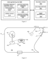
- Fig. 3 shows a modular block diagram of the robot gardening tool system according to embodiments of the present invention.
- the robot gardening tool system comprises a robot gardening tool 300 and a boundary module 360.
- the robot gardening tool 300 may for example be the robot gardening tool 100 illustrated in Figs. 1A - 1C or the robot gardening tool 200 illustrated in Fig. 2 .
- the boundary module 360 delimits a work area and/or a non-work area of the robot gardening tool 300.
- the boundary module 360 comprises at least one boundary element 362, the boundary element 362 defining a periphery or boundary of the work area and/or non-work area.
- the boundary may be a physical boundary (e.g. a fence, wall, etc.), or a virtual boundary, e.g. a boundary delimited by a boundary line or beacon or with the aid of a satellite apparatus.
- the boundary module 360 further comprises a signal generating unit 364, e.g. a signal generator.
- the signal generating unit 364 can generate an excitation signal and send the excitation signal to the boundary element 362.
- the boundary element comprises a boundary line.
- the signal generating unit generates a current as an excitation signal, and the current flows through the boundary line, generating an electromagnetic field as a boundary signal.
- the electromagnetic field signal is stronger along the boundary line and weaker far away from the boundary line.
- the robot gardening tool can determine how far away it is from the boundary of the work area. That is, the boundary line carrying the electromagnetic field signal delimits the periphery or boundary of the work area or non-work area of the robot gardening tool. Different boundary elements can generate different boundary signals, to distinguish between the work area and non-work area.
- the robot gardening tool 300 comprises a boundary detection apparatus 310, a jamming detection apparatus 320 and a control apparatus 340. These apparatuses may be provided separately or integrated in the same circuit module.
- the boundary detection apparatus 310 can detect the boundary element 362.
- the boundary is configured as a virtual boundary, e.g. a boundary line, a beacon, a boundary delimited with the aid of a satellite apparatus, etc.
- the boundary detection apparatus 310 may for example comprise a signal receiving module 312.
- the signal receiving module 312 for example comprises one or more sensor disposed on the frame or chassis of the robot gardening tool 300 or at another suitable position.
- the signal receiving module 312 is an electromagnetic signal sensor capable of sensing the boundary signal generated by the boundary module 360.
- a strength threshold e.g.
- the boundary detection apparatus 310 generates or issues a feedback signal S i .
- the signal receiving module 312 is a position sensor capable of detecting and judging a distance to the virtual boundary. When the distance is less than a distance threshold, the boundary detection apparatus 310 generates or issues a feedback signal S i .
- the sensing of the boundary by the signal receiving module 312 does not require the robot gardening tool 300 to necessarily come into physical contact with part of the boundary module 360 (e.g. the boundary element 362) or overlap the boundary physically, but of course, physical contact or overlap with part thereof is not ruled out.
- the boundary is configured as a physical boundary, e.g. a wall, fence, etc.
- the boundary detection apparatus 310 further comprises a collision sensor 314, e.g. an accelerometer.
- the collision sensor 314 senses that part of the robot gardening tool 300 (e.g. the front end) has collided with the boundary, the boundary detection apparatus 310 issues a feedback signal S i .
- the feedback signal S i generated or issued by the boundary detection apparatus 310 is a continuous signal, not a discrete signal.
- the continuous signal comprises a part that exceeds a threshold and a part that is lower than a threshold.
- the jamming detection apparatus communicates with the boundary detection apparatus 310.
- the inventors of the present invention first realized that it is possible to detect and judge whether the robot gardening tool 300 is jammed based on the pattern of the feedback signal S i generated by the boundary detection apparatus 310.
- This method of detection and judgement does not require additional sensors or equipment to be provided for the robot gardening tool 300; it only needs to rely on an existing electromagnetic signal sensor, position sensor or acceleration sensor.
- the present invention enables detection and judgement of whether the robot gardening tool 300 is jammed, in a low-cost and reliable way.
- the jamming detection apparatus 320 upon receiving each feedback signal S i , the jamming detection apparatus 320 records the time of occurrence t i of the feedback signal S i .
- the jamming detection apparatus 320 calculates the time interval ⁇ t i between two consecutive feedback signals S i and S i+1 , and judges whether the robot gardening tool 300 is jammed based on the time interval ⁇ t i .
- the jamming detection apparatus 320 does not record the absolute time of occurrence t i of the feedback signal S i , instead merely recording the relative time interval ⁇ t i between two consecutive feedback signals S i and S i+1 .
- the jamming detection apparatus 320 determines that the robot gardening tool 300 is jammed. In other embodiments, when n consecutive time intervals ⁇ t i , ⁇ t i+1 ... ⁇ t i+n-1 are all less than a time threshold, the jamming detection apparatus 320 determines that the robot gardening tool 300 is jammed. For example, n is selected from one of 2 - 10, e.g. 2, 3, 4, 5, 6, 7, 8, 9, 10. In other embodiments, when m time intervals of n consecutive time intervals ⁇ t i , ⁇ t i+1 ...
- n is selected from one of 2 - 10, e.g. 2, 3, 4, 5, 6, 7, 8, 9, 10, m is selected from one of 2 - 9, e.g. 2, 3, 4, 5, 6, 7, 8, 9, and m ⁇ n.
- the time threshold may for example be selectively set by the user or set in advance according to factors such as the speed of advance of the robot gardening tool 300, the size of the work area, etc. In some embodiments, the time threshold may be 5 - 120 seconds, 10 - 90 seconds, 20 - 60 seconds, 30 seconds, etc.
- the jamming detection apparatus 320 receives the continuous feedback signal S i , and records each time t i when the feedback signal S i exceeds a threshold. No further details are described here.
- the jamming detection apparatus 320 determines that the robot gardening tool 300 is jammed, it communicates with the control apparatus 340.
- the control apparatus 340 controls the robot gardening tool 300 to perform an extrication operation.
- the extrication operation may be one or more of predetermined operations, e.g. retreat, turning, or travelling along a specific route, etc.
- the robot gardening tool further comprises a trajectory recording apparatus 330.
- the trajectory recording apparatus 330 can record a trajectory of advance of the robot gardening tool 300.
- the trajectory of advance may for example be characterized as a motion trajectory obtained on the basis of satellite navigation, or as an operating state of the motive power apparatus within a period of time.
- the extrication operation for example comprises causing the robot gardening tool 300 to retreat along the recorded trajectory of advance for a predetermined time (e.g. 10 - 180 seconds, 30 - 150 seconds, 60 - 120 seconds, etc.) or a predetermined distance (e.g. 0.5 - 20 metres, 1 - 15 metres, 2 - 10 metres, 5 metres, etc.), and optionally, turn aside through a predetermined angle (e.g. 10 - 180 degrees, 20 - 150 degrees, 30 - 90 degrees, 60 degrees, etc.) before continuing to advance.
- the extrication operation comprises causing the robot gardening tool 300 to advance along at least one boundary element (e.g. boundary line) for a predetermined time (e.g.
- the predetermined time mentioned above may be a random time
- the predetermined distance mentioned above may be a random distance
- the predetermined angle mentioned above may be a random angle
- the control apparatus 340 further comprises an alarm apparatus, e.g. a sound alarm. If jamming of the robot gardening tool 300 is detected again within a period of time (e.g. 30 - 180 seconds, 60 - 120 seconds, etc.) after completion of the extrication operation, an alert is issued to the user, to alert the user to deal with the situation. This is advantageous in some cases. In general, once the robot gardening tool has extricated itself from the jam, if it becomes jammed again within a specific time, this might indicate that self-extrication is more difficult in the area in question, so assistance by manual intervention can be sought, e.g. a person can go and shift the robot gardening tool.
- a period of time e.g. 30 - 180 seconds, 60 - 120 seconds, etc.
- Fig. 4 shows a robot gardening tool in a work area, and detection of whether it is jammed in the work area, according to embodiments of the present invention.
- the robot gardening tool 400 may for example be the robot gardening tool 100 illustrated in Figs. 1A - 1C or the robot gardening tool 200 illustrated in Fig. 2 or the robot gardening tool 300 illustrated in Fig. 3 .
- the boundary module comprises a boundary line 42 and a signal generating unit 44.
- the signal generating unit 44 is for example a current generator that generates an excitation current (an example of an excitation signal).
- the boundary line 42 is for example a conductive wire carrying the excitation current; the conductive wire receives the excitation current and generates a boundary signal.
- the boundary line 42 delimits the boundary of a work area 402.
- the signal generating unit 44 is illustrated as being located on the boundary, this is not necessary. In some embodiments, the signal generating unit 44 may be located outside or inside the boundary, and then electrically connected to the boundary line 42.
- the boundary signal may be of a suitable type, for example being a signal having a specific frequency and a specific waveform (e.g. a sine wave, a cosine wave, a square wave, etc., or a superimposition of one or more waveforms).
- the boundary signal may be the alternating occurrence or superimposition of an emitted signal emitted by the signal generating unit 44 and an auxiliary signal.
- the boundary signal may also be a periodic or non-periodic signal appearing through the alternating occurrence of an emitted signal emitted by the signal generating unit 44 and a vacant signal.
- the boundary signal may also be a signal whose signal period and/or phase changes with time.
- the boundary signal may also be the alternating occurrence or superimposition of one or more different emitted signals.
- the robot gardening tool 400 may subject the boundary signal to processing, such as amplification, filtering or phase modulation.
- the boundary line 42 emits 4 slot square wave signals (1, 1, -1, 1), which are immediately followed by 279 empty slots.
- the robot gardening tool continuously detects the signal, capturing the signal once every 300 time slots, and filters the signal to detect whether where is a boundary signal and the strength and phase of the boundary signal.
- the boundary module may also comprise boundary elements delimiting the boundaries of these undesirable objects; in this embodiment, these boundary elements are illustrated as boundary lines 42a and 42b.
- the work area 402 also contains regions which are likely to cause jamming of the robot gardening tool 400, e.g. an area 405 between the tree 401 and the obstacle 403, a first corner area 407, and a second corner area 409, etc.
- FIG. 4 illustrates judgement and processing for jamming of the robot gardening tool 400 in the second corner area 409. As shown, it is illustrated that in response to the robot gardening tool 400 advancing to position p1 in direction a (indicated by an arrow, likewise hereinbelow), the boundary detection apparatus of the robot gardening tool 400 issues a feedback signal S 1 , and the jamming detection apparatus thereof receives the feedback signal S 1 and records the time t 1 .
- the triggering of the feedback signal S 1 may be due to the boundary signal (a magnetic field signal in this embodiment) sensed by the robot gardening tool being greater than a strength threshold (a predetermined magnetic field strength in this embodiment), or may be due to the robot gardening tool sensing that it has collided with or overlapped the boundary line 42.
- a strength threshold a predetermined magnetic field strength in this embodiment
- position p1 is illustrated as being located on the boundary delimited by the boundary line 42, this is not necessary; position p1 might be located at a certain distance from the boundary at the inner side thereof, as long as the boundary signal sensed by the robot gardening tool as this distance attains a certain value. This similarly applies to position p2 and position p3 which will be illustrated below.
- the robot gardening tool 400 may advance in direction b according to a set plan. For example, the robot gardening tool 400 may turn through a certain angle, or first retreat for a certain distance or time and then turn through a certain angle, and then advance in direction b.
- the boundary detection apparatus of the robot gardening tool 400 issues a feedback signal S 2
- the trigger conditions for feedback signal S 2 may be similar to those for feedback signal S 1 , or may be slightly different.
- the robot gardening tool 400 may advance in direction c according to a set plan.
- the boundary detection apparatus of the robot gardening tool 400 issues a feedback signal S 3
- the trigger conditions for feedback signal S 3 may be similar to those for feedback signal S 1 , or may be slightly different.
- the jamming detection apparatus of the robot gardening tool 400 determines that the robot gardening tool 400 is jammed, and the control apparatus thereof then instructs the robot gardening tool 400 to advance for a predetermined time or a predetermined distance along a predetermined route or direction (in this embodiment, in direction e which coincides with the boundary) to reach position p4, thereby extricating itself from the jammed state.
- the robot gardening tool 400 turns through a certain angle towards the work area 402 (this angle might be predetermined, e.g. 30 degrees, or may be randomly generated), and the continues to advance to perform normal work.
- the jamming detection apparatus of the robot gardening tool 400 determines that the robot gardening tool 400 is not jammed. At position p3, the robot gardening tool 400 will for example advance in direction d and continue to perform normal work.
- a time threshold e.g. 60 seconds
- the jamming detection apparatus of the robot gardening tool 400 determines that the robot gardening tool 400 is jammed, and then begins an extrication operation at position p2.
- Fig. 4 only illustrates the generation of trigger signals at three positions (position p1, position p2, position p3).
- trigger signals might be generated at more positions, e.g. 5 positions, 10 positions or 15 positions.
- the robot gardening tool might only be determined as being jammed when 5, 8 or even more consecutive time intervals are all less than a time threshold. This is advantageous in some cases. For example, misjudgements can be reduced.
- the robot gardening tool will then activate an extrication operation and leave the area where it is located, no longer performing an operation on the area where it is located, and may even introduce manual intervention which is actually not necessary. That is, setting multiple consecutive time intervals to all satisfy the determination condition of being less than a time threshold can encourage the robot gardening tool to work for as long a time as possible in an area where jamming is likely, and this is conducive to performing a better operation on such an area (e.g. removing more grass).
- the predetermined angle, predetermined time and predetermined distance mentioned in conjunction with Fig. 4 may be set in advance or randomly generated. In some cases, it is advantageous to use an angle, time and distance that are randomly generated. Taking as an example the advance of the robot gardening tool from position p3 to position p4 in direction e, due to the fact that the time or distance of advance is randomly generated, position p4 is thus random, and this is advantageous for the robot gardening tool advancing towards the work area from different positions on the boundary; consequently, the object of the operation (e.g. lawn) in the work area can undergo a more uniform operation. The robot gardening tool turning through a random angle at position p4 also promotes this beneficial result.
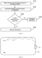
- Fig. 5 shows a method for a robot gardening tool in embodiments of the present invention.
- the method may for example be performed by the robot gardening tool 100 illustrated in Figs. 1A - 1C or the robot gardening tool 200 illustrated in Fig. 2 or the robot gardening tool 300 illustrated in Fig. 3 or the robot gardening tool 400 illustrated in Fig. 4 .
- a sensor of the robot gardening tool may detect an electromagnetic field generated by a boundary line carrying an electric signal, or detect a boundary signal created by a suitable signal source such as a beacon or satellite apparatus.
- a feedback signal S i is generated.
- the generation of the feedback signal S i is based on a predetermined trigger condition (e.g. a detected boundary signal reaching a certain threshold, or a collision or overlap occurring with a boundary element or boundary, etc.), and indicates that the robot gardening tool has already entered a predetermined boundary area.
- the predetermined boundary area may be where the distance to the boundary is less than a predetermined value, or overlap occurs (e.g. the front end of the robot gardening tool touches or overlaps the boundary).
- Fig. 6 shows a return route of a robot gardening tool according to embodiments of the present invention.
- a boundary line 62 defines a work area 602.
- the robot gardening tool 600 can work in the work area 602.
- Fig. 6 also shows a charging station 68; the charging station 68 may comprise a signal generating unit for generating a signal (not shown).
- the robot gardening tool 600 When the charge level of a battery of the robot gardening tool 600 is lower than a certain level, the robot gardening tool 600 needs to return to the charging station 68 to charge. In some embodiments, when it needs to charge, the robot gardening tool 600 will return to the charging station 68 along the boundary line 62 (a first return route).
- the robot gardening tool 600 when it needs to charge, the robot gardening tool 600 will return to the charging station 68 along a second return route different from the first return route.
- the second return route may comprise a route that deviates from the boundary line by a predetermined distance, or may be a curved route that deviates from the boundary line by a varying distance, or a combination thereof.
- the second return route may be a combination of the abovementioned routes having several different trajectories.
- the robot gardening tool 600 When each return operation takes place, the robot gardening tool 600 thereby or randomly selects one of the routes.
- the second return route may also be a random route. As an example, Fig. 6 shows one of the routes: second return route 66.
- the second return route it is advantageous to use the second return route. For example, this can avoid excessive destruction of or damage to the grass on this same route caused by the robot gardening tool returning along the boundary line every time. In ground surface environments with higher humidity, the destruction caused by the robot gardening tool along a fixed route might be significant.
- the second return route shown in Fig. 6 can avoid or mitigate such disadvantages.
- the second return route may be set in advance. In other embodiments, the second return route is randomly generated. The randomly generated second return route can further mitigate the destruction or damage caused to the work area.
Landscapes
- Life Sciences & Earth Sciences (AREA)
- Environmental Sciences (AREA)
- Engineering & Computer Science (AREA)
- Aviation & Aerospace Engineering (AREA)
- Radar, Positioning & Navigation (AREA)
- Remote Sensing (AREA)
- Physics & Mathematics (AREA)
- General Physics & Mathematics (AREA)
- Automation & Control Theory (AREA)
- Manipulator (AREA)
- Control Of Position, Course, Altitude, Or Attitude Of Moving Bodies (AREA)
Applications Claiming Priority (1)
| Application Number | Priority Date | Filing Date | Title |
|---|---|---|---|
| CN202111151237.6A CN115868303A (zh) | 2021-09-29 | 2021-09-29 | 机器人园林工具系统及用于机器人园林工具的方法 |
Publications (2)
| Publication Number | Publication Date |
|---|---|
| EP4159019A1 true EP4159019A1 (de) | 2023-04-05 |
| EP4159019B1 EP4159019B1 (de) | 2026-03-18 |
Family
ID=83271418
Family Applications (1)
| Application Number | Title | Priority Date | Filing Date |
|---|---|---|---|
| EP22194950.6A Active EP4159019B1 (de) | 2021-09-29 | 2022-09-09 | Robotergartenwerkzeugsystem und verfahren für robotergartenwerkzeug |
Country Status (5)
| Country | Link |
|---|---|
| US (1) | US20230101852A1 (de) |
| EP (1) | EP4159019B1 (de) |
| CN (1) | CN115868303A (de) |
| AU (1) | AU2022221523A1 (de) |
| CA (1) | CA3174800A1 (de) |
Citations (4)
| Publication number | Priority date | Publication date | Assignee | Title |
|---|---|---|---|---|
| EP2412221A2 (de) * | 2010-07-28 | 2012-02-01 | Deere & Company | Mähroboterrandsensorsystem und Mähroboter |
| US20160014955A1 (en) * | 2012-12-07 | 2016-01-21 | Viking Gmbh | Method for Controlling a Self-Propelled Lawnmower |
| WO2021115869A1 (en) * | 2019-12-12 | 2021-06-17 | Husqvarna Ab | Exit path determination for a robotic work tool |
| US20210263521A1 (en) * | 2018-11-15 | 2021-08-26 | Honda Motor Co., Ltd. | Autonomous work machine, method of controlling the same, and storage medium |
Family Cites Families (5)
| Publication number | Priority date | Publication date | Assignee | Title |
|---|---|---|---|---|
| US8838291B2 (en) * | 2010-07-07 | 2014-09-16 | Husqvarna Ab | Communication and safety device for boundary aided systems |
| US20120029752A1 (en) * | 2010-07-28 | 2012-02-02 | Johnson David A | Robotic Mower Stuck Detection System |
| CN110687903B (zh) * | 2018-06-19 | 2022-07-08 | 速感科技(北京)有限公司 | 可移动机器人受困判断方法、装置与运动控制方法、装置 |
| WO2020041985A1 (en) * | 2018-08-28 | 2020-03-05 | Tti (Macao Commercial Offshore) Limited | An autonomous lawn mower and a system for navigating thereof |
| CN111197987A (zh) * | 2020-02-26 | 2020-05-26 | 深圳市银星智能科技股份有限公司 | 一种困境识别方法、装置以及计算机存储介质 |
-
2021
- 2021-09-29 CN CN202111151237.6A patent/CN115868303A/zh active Pending
-
2022
- 2022-08-26 AU AU2022221523A patent/AU2022221523A1/en active Pending
- 2022-09-09 EP EP22194950.6A patent/EP4159019B1/de active Active
- 2022-09-16 CA CA3174800A patent/CA3174800A1/en active Pending
- 2022-09-20 US US17/948,683 patent/US20230101852A1/en active Pending
Patent Citations (4)
| Publication number | Priority date | Publication date | Assignee | Title |
|---|---|---|---|---|
| EP2412221A2 (de) * | 2010-07-28 | 2012-02-01 | Deere & Company | Mähroboterrandsensorsystem und Mähroboter |
| US20160014955A1 (en) * | 2012-12-07 | 2016-01-21 | Viking Gmbh | Method for Controlling a Self-Propelled Lawnmower |
| US20210263521A1 (en) * | 2018-11-15 | 2021-08-26 | Honda Motor Co., Ltd. | Autonomous work machine, method of controlling the same, and storage medium |
| WO2021115869A1 (en) * | 2019-12-12 | 2021-06-17 | Husqvarna Ab | Exit path determination for a robotic work tool |
Also Published As
| Publication number | Publication date |
|---|---|
| US20230101852A1 (en) | 2023-03-30 |
| CA3174800A1 (en) | 2023-03-29 |
| CN115868303A (zh) | 2023-03-31 |
| EP4159019B1 (de) | 2026-03-18 |
| AU2022221523A1 (en) | 2023-04-13 |
Similar Documents
| Publication | Publication Date | Title |
|---|---|---|
| EP2806325B1 (de) | Hausrobotersystem | |
| US5204814A (en) | Autonomous lawn mower | |
| EP3800979B1 (de) | Autonome bodenpflegemaschinen mit wegplanung für fallen- und hindernisvermeidung | |
| EP4179400B1 (de) | Autonome maschinennavigation unter verwendung von reflexionen von unterirdischen objekten | |
| CN104179116B (zh) | 具有位置指示器系统的铣刨机 | |
| US20200045880A1 (en) | System and method for controlling and monitoring operation of an autonomous robot | |
| EP1149333B1 (de) | Autonom verfahrbares gerät, insbesondere staubsauger | |
| EP2829937B1 (de) | Roboter-Arbeitsgerät für einen begrenzten Arbeitsbereich | |
| EP3798781B1 (de) | Automatischer mäher und steuerungsverfahren | |
| EP3876068B1 (de) | Automatisches arbeitssystem, automatische gehvorrichtung und lenkverfahren dafür | |
| CN107422723B (zh) | 覆盖机器人导航 | |
| GB2358843A (en) | An autonomous mobile apparatus for performing work within a pre-defined area | |
| CN112799399A (zh) | 自动割草机的路径规划方法、系统、设备及自动割草机 | |
| CN104981747A (zh) | 用于控制自行式割草机的方法 | |
| EP4159019A1 (de) | Robotergartenwerkzeugsystem und verfahren für robotergartenwerkzeug | |
| CN111949023B (zh) | 一种自行走设备的边界探测方法和自行走设备 | |
| JPS5911410A (ja) | 無人走行作業車 | |
| CN222838368U (zh) | 自主作业系统的标记设备 | |
| CN115328107A (zh) | 智能割草系统及智能割草设备 | |
| CN119847150A (zh) | 一种用于窄通道作业的自行走设备 | |
| CN119412017A (zh) | 一种钻机的防触电系统 | |
| WO2020228742A1 (zh) | 自动工作系统及其工作方法、自行走设备 | |
| JPH03150605A (ja) | 自動走行作業車の操向制御装置 |
Legal Events
| Date | Code | Title | Description |
|---|---|---|---|
| PUAI | Public reference made under article 153(3) epc to a published international application that has entered the european phase |
Free format text: ORIGINAL CODE: 0009012 |
|
| STAA | Information on the status of an ep patent application or granted ep patent |
Free format text: STATUS: THE APPLICATION HAS BEEN PUBLISHED |
|
| AK | Designated contracting states |
Kind code of ref document: A1 Designated state(s): AL AT BE BG CH CY CZ DE DK EE ES FI FR GB GR HR HU IE IS IT LI LT LU LV MC MK MT NL NO PL PT RO RS SE SI SK SM TR |
|
| STAA | Information on the status of an ep patent application or granted ep patent |
Free format text: STATUS: REQUEST FOR EXAMINATION WAS MADE |
|
| 17P | Request for examination filed |
Effective date: 20231005 |
|
| RBV | Designated contracting states (corrected) |
Designated state(s): AL AT BE BG CH CY CZ DE DK EE ES FI FR GB GR HR HU IE IS IT LI LT LU LV MC MK MT NL NO PL PT RO RS SE SI SK SM TR |
|
| STAA | Information on the status of an ep patent application or granted ep patent |
Free format text: STATUS: EXAMINATION IS IN PROGRESS |
|
| 17Q | First examination report despatched |
Effective date: 20250227 |
|
| GRAP | Despatch of communication of intention to grant a patent |
Free format text: ORIGINAL CODE: EPIDOSNIGR1 |
|
| STAA | Information on the status of an ep patent application or granted ep patent |
Free format text: STATUS: GRANT OF PATENT IS INTENDED |
|
| INTG | Intention to grant announced |
Effective date: 20251013 |
|
| GRAS | Grant fee paid |
Free format text: ORIGINAL CODE: EPIDOSNIGR3 |
|
| GRAA | (expected) grant |
Free format text: ORIGINAL CODE: 0009210 |
|
| STAA | Information on the status of an ep patent application or granted ep patent |
Free format text: STATUS: THE PATENT HAS BEEN GRANTED |
|
| AK | Designated contracting states |
Kind code of ref document: B1 Designated state(s): AL AT BE BG CH CY CZ DE DK EE ES FI FR GB GR HR HU IE IS IT LI LT LU LV MC MK MT NL NO PL PT RO RS SE SI SK SM TR |
|
| REG | Reference to a national code |
Ref country code: CH Ref legal event code: F10 Free format text: ST27 STATUS EVENT CODE: U-0-0-F10-F00 (AS PROVIDED BY THE NATIONAL OFFICE) Effective date: 20260318 Ref country code: GB Ref legal event code: FG4D |