EP4158727B1 - Phased array front-end devices - Google Patents
Phased array front-end devices Download PDFInfo
- Publication number
- EP4158727B1 EP4158727B1 EP21817204.7A EP21817204A EP4158727B1 EP 4158727 B1 EP4158727 B1 EP 4158727B1 EP 21817204 A EP21817204 A EP 21817204A EP 4158727 B1 EP4158727 B1 EP 4158727B1
- Authority
- EP
- European Patent Office
- Prior art keywords
- section
- planar component
- transmit
- receive
- waves
- Prior art date
- Legal status (The legal status is an assumption and is not a legal conclusion. Google has not performed a legal analysis and makes no representation as to the accuracy of the status listed.)
- Active
Links
Images








Classifications
-
- H—ELECTRICITY
- H01—ELECTRIC ELEMENTS
- H01Q—ANTENNAS, i.e. RADIO AERIALS
- H01Q21/00—Antenna arrays or systems
- H01Q21/06—Arrays of individually energised antenna units similarly polarised and spaced apart
- H01Q21/061—Two dimensional planar arrays
- H01Q21/064—Two dimensional planar arrays using horn or slot aerials
-
- G—PHYSICS
- G01—MEASURING; TESTING
- G01S—RADIO DIRECTION-FINDING; RADIO NAVIGATION; DETERMINING DISTANCE OR VELOCITY BY USE OF RADIO WAVES; LOCATING OR PRESENCE-DETECTING BY USE OF THE REFLECTION OR RERADIATION OF RADIO WAVES; ANALOGOUS ARRANGEMENTS USING OTHER WAVES
- G01S13/00—Systems using the reflection or reradiation of radio waves, e.g. radar systems; Analogous systems using reflection or reradiation of waves whose nature or wavelength is irrelevant or unspecified
- G01S13/003—Bistatic radar systems; Multistatic radar systems
-
- G—PHYSICS
- G01—MEASURING; TESTING
- G01S—RADIO DIRECTION-FINDING; RADIO NAVIGATION; DETERMINING DISTANCE OR VELOCITY BY USE OF RADIO WAVES; LOCATING OR PRESENCE-DETECTING BY USE OF THE REFLECTION OR RERADIATION OF RADIO WAVES; ANALOGOUS ARRANGEMENTS USING OTHER WAVES
- G01S13/00—Systems using the reflection or reradiation of radio waves, e.g. radar systems; Analogous systems using reflection or reradiation of waves whose nature or wavelength is irrelevant or unspecified
- G01S13/88—Radar or analogous systems specially adapted for specific applications
- G01S13/93—Radar or analogous systems specially adapted for specific applications for anti-collision purposes
- G01S13/931—Radar or analogous systems specially adapted for specific applications for anti-collision purposes of land vehicles
-
- G—PHYSICS
- G01—MEASURING; TESTING
- G01S—RADIO DIRECTION-FINDING; RADIO NAVIGATION; DETERMINING DISTANCE OR VELOCITY BY USE OF RADIO WAVES; LOCATING OR PRESENCE-DETECTING BY USE OF THE REFLECTION OR RERADIATION OF RADIO WAVES; ANALOGOUS ARRANGEMENTS USING OTHER WAVES
- G01S7/00—Details of systems according to groups G01S13/00, G01S15/00, G01S17/00
- G01S7/02—Details of systems according to groups G01S13/00, G01S15/00, G01S17/00 of systems according to group G01S13/00
- G01S7/024—Details of systems according to groups G01S13/00, G01S15/00, G01S17/00 of systems according to group G01S13/00 using polarisation effects
-
- G—PHYSICS
- G01—MEASURING; TESTING
- G01S—RADIO DIRECTION-FINDING; RADIO NAVIGATION; DETERMINING DISTANCE OR VELOCITY BY USE OF RADIO WAVES; LOCATING OR PRESENCE-DETECTING BY USE OF THE REFLECTION OR RERADIATION OF RADIO WAVES; ANALOGOUS ARRANGEMENTS USING OTHER WAVES
- G01S7/00—Details of systems according to groups G01S13/00, G01S15/00, G01S17/00
- G01S7/02—Details of systems according to groups G01S13/00, G01S15/00, G01S17/00 of systems according to group G01S13/00
- G01S7/03—Details of HF subsystems specially adapted therefor, e.g. common to transmitter and receiver
-
- H—ELECTRICITY
- H01—ELECTRIC ELEMENTS
- H01Q—ANTENNAS, i.e. RADIO AERIALS
- H01Q1/00—Details of, or arrangements associated with, antennas
- H01Q1/27—Adaptation for use in or on movable bodies
- H01Q1/32—Adaptation for use in or on road or rail vehicles
- H01Q1/3208—Adaptation for use in or on road or rail vehicles characterised by the application wherein the antenna is used
- H01Q1/3233—Adaptation for use in or on road or rail vehicles characterised by the application wherein the antenna is used particular used as part of a sensor or in a security system, e.g. for automotive radar, navigation systems
-
- H—ELECTRICITY
- H01—ELECTRIC ELEMENTS
- H01Q—ANTENNAS, i.e. RADIO AERIALS
- H01Q15/00—Devices for reflection, refraction, diffraction or polarisation of waves radiated from an antenna, e.g. quasi-optical devices
- H01Q15/02—Refracting or diffracting devices, e.g. lens, prism
- H01Q15/06—Refracting or diffracting devices, e.g. lens, prism comprising plurality of wave-guiding channels of different length
-
- H—ELECTRICITY
- H01—ELECTRIC ELEMENTS
- H01Q—ANTENNAS, i.e. RADIO AERIALS
- H01Q21/00—Antenna arrays or systems
- H01Q21/0006—Particular feeding systems
- H01Q21/0031—Parallel-plate fed arrays; Lens-fed arrays
-
- H—ELECTRICITY
- H01—ELECTRIC ELEMENTS
- H01Q—ANTENNAS, i.e. RADIO AERIALS
- H01Q21/00—Antenna arrays or systems
- H01Q21/24—Combinations of antenna units polarised in different directions for transmitting or receiving circularly and elliptically polarised waves or waves linearly polarised in any direction
-
- H—ELECTRICITY
- H01—ELECTRIC ELEMENTS
- H01Q—ANTENNAS, i.e. RADIO AERIALS
- H01Q21/00—Antenna arrays or systems
- H01Q21/24—Combinations of antenna units polarised in different directions for transmitting or receiving circularly and elliptically polarised waves or waves linearly polarised in any direction
- H01Q21/245—Combinations of antenna units polarised in different directions for transmitting or receiving circularly and elliptically polarised waves or waves linearly polarised in any direction provided with means for varying the polarisation
-
- H—ELECTRICITY
- H01—ELECTRIC ELEMENTS
- H01Q—ANTENNAS, i.e. RADIO AERIALS
- H01Q25/00—Antennas or antenna systems providing at least two radiating patterns
- H01Q25/007—Antennas or antenna systems providing at least two radiating patterns using two or more primary active elements in the focal region of a focusing device
- H01Q25/008—Antennas or antenna systems providing at least two radiating patterns using two or more primary active elements in the focal region of a focusing device lens fed multibeam arrays
-
- H—ELECTRICITY
- H01—ELECTRIC ELEMENTS
- H01Q—ANTENNAS, i.e. RADIO AERIALS
- H01Q3/00—Arrangements for changing or varying the orientation or the shape of the directional pattern of the waves radiated from an antenna or antenna system
- H01Q3/24—Arrangements for changing or varying the orientation or the shape of the directional pattern of the waves radiated from an antenna or antenna system varying the orientation by switching energy from one active radiating element to another, e.g. for beam switching
- H01Q3/245—Arrangements for changing or varying the orientation or the shape of the directional pattern of the waves radiated from an antenna or antenna system varying the orientation by switching energy from one active radiating element to another, e.g. for beam switching in the focal plane of a focussing device
-
- H—ELECTRICITY
- H01—ELECTRIC ELEMENTS
- H01Q—ANTENNAS, i.e. RADIO AERIALS
- H01Q3/00—Arrangements for changing or varying the orientation or the shape of the directional pattern of the waves radiated from an antenna or antenna system
- H01Q3/26—Arrangements for changing or varying the orientation or the shape of the directional pattern of the waves radiated from an antenna or antenna system varying the relative phase or relative amplitude of energisation between two or more active radiating elements; varying the distribution of energy across a radiating aperture
- H01Q3/2682—Time delay steered arrays
-
- H—ELECTRICITY
- H01—ELECTRIC ELEMENTS
- H01Q—ANTENNAS, i.e. RADIO AERIALS
- H01Q9/00—Electrically-short antennas having dimensions not more than twice the operating wavelength and consisting of conductive active radiating elements
- H01Q9/04—Resonant antennas
- H01Q9/0407—Substantially flat resonant element parallel to ground plane, e.g. patch antenna
-
- G—PHYSICS
- G01—MEASURING; TESTING
- G01S—RADIO DIRECTION-FINDING; RADIO NAVIGATION; DETERMINING DISTANCE OR VELOCITY BY USE OF RADIO WAVES; LOCATING OR PRESENCE-DETECTING BY USE OF THE REFLECTION OR RERADIATION OF RADIO WAVES; ANALOGOUS ARRANGEMENTS USING OTHER WAVES
- G01S13/00—Systems using the reflection or reradiation of radio waves, e.g. radar systems; Analogous systems using reflection or reradiation of waves whose nature or wavelength is irrelevant or unspecified
- G01S13/02—Systems using reflection of radio waves, e.g. primary radar systems; Analogous systems
- G01S2013/0236—Special technical features
- G01S2013/0245—Radar with phased array antenna
-
- G—PHYSICS
- G01—MEASURING; TESTING
- G01S—RADIO DIRECTION-FINDING; RADIO NAVIGATION; DETERMINING DISTANCE OR VELOCITY BY USE OF RADIO WAVES; LOCATING OR PRESENCE-DETECTING BY USE OF THE REFLECTION OR RERADIATION OF RADIO WAVES; ANALOGOUS ARRANGEMENTS USING OTHER WAVES
- G01S13/00—Systems using the reflection or reradiation of radio waves, e.g. radar systems; Analogous systems using reflection or reradiation of waves whose nature or wavelength is irrelevant or unspecified
- G01S13/02—Systems using reflection of radio waves, e.g. primary radar systems; Analogous systems
- G01S2013/0236—Special technical features
- G01S2013/0245—Radar with phased array antenna
- G01S2013/0254—Active array antenna
Definitions
- the present disclosure relates to apparatus and methods of detecting objects or obstacles and, more particularly, apparatus and methods of detecting objects or obstacles and recognizing with high accuracy the type of object that.
- a phased array radar system may be a radar system that manipulates the phase of one or more radio waves transmitted by a transmitting and receiving module and uses a pattern of constructive and destructive interference created by the radio waves transmitted with different phases to steer a beam of radio waves in a desired direction.
- US 2013/027240 describes a radar system that includes a transmitting assembly, a receiving assembly, a control unit and a signal processing unit.
- the transmitting assembly receives an input signal and transmits an incident radar signal.
- the transmitting assembly includes a Rotman lens having a lens cavity, a plurality of beam ports, a plurality of array ports and a patch antenna assembly.
- the lens cavity has a lens gap between 10 microns to 120 microns.
- the patch antenna assembly includes a plurality of antenna arrays operable to receive a plurality of time-delayed, in-phase signals from the Rotman lens and to transmit the incident radar signal towards a target.
- the receiving assembly receives a reflected radar signal and produces an output signal.
- the signal processing unit compares the input signal to the output signal and implements an algorithm determining the range, velocity and position of the target.
- a radar system that comprises a transmit front end device and a receive front end device is defined in claim 1.
- a front end device of a radar system comprises a planar component through which electromagnetic waves propagate.
- the planar component includes a first end, a second end, a cavity space, and a linear array of antennas.
- the second end located opposite the first end.
- the cavity space is bounded by beam ports along a first side of the cavity space and by array ports along a second side of the cavity space.
- the cavity space is in operative communication with the beam ports and with the array ports to form a Rotman lens.
- the cavity space is further bounded by radio frequency absorbers along a third side and a fourth side of the cavity space.
- the second side is located opposite the first side, and the fourth side is located opposite the third side.
- the array of antennas is located along the second end of the planar component. Each of the antennas is in operative communication with a corresponding one of the array ports.
- the radio frequency absorbers include triangular teeth having vertices, and the triangular teeth are configured such that lines connecting adjacent vertices are substantially normal to a curvature of a wavefront of the waves in the cavity space.
- a method for detecting an object is provided in claim 15.
- Range-finding systems use reflected waves to discern, for example, the presence, distance and/or velocity of objects.
- Radio Detection And Ranging (radar) and other rangefinding systems have been widely employed in applications, by way of non-limiting example, in autonomous vehicles such as self-driving cars, as well as in wireless communications modems of the type employed, such as in Massive-MIMO (multiple-in-multiple-out) networks, 5G wireless telecommunications, all by way of non-limiting example.
- Massive-MIMO multiple-in-multiple-out
- 5G wireless telecommunications all by way of non-limiting example.
- the radar system may include optimized RF front-end device(s) aiding in achieving higher resolution by improving azimuth resolution, elevation resolution, or any combination thereof.
- Azimuth resolution is the ability of a radar system to distinguish between objects at similar range but different bearings.
- Elevation resolution is the ability of a radar system to distinguish between objects at similar range but different elevation.
- Angular resolution characteristics of a radar are determined by the antenna beam-width represented by the -3 dB angle which is defined by the half-power (-3 dB) points.
- radar system or phased array system disclosed herein may have a -3 dB beam-width of 1.5 degree or less in both azimuth resolution and elevation resolution.
- the radar system can be configured to achieve finer azimuth resolution and elevation resolution by employing an RF front-end device having two linear antennas arrays arranged perpendicularly and a Rotman lens as a phase shifting network, as will be described below.
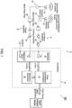
- FIG. 1 shows a schematic illustration of an example radar system 100 having the abovementioned functionalities.
- the radar system 100 may include a millimeter wave radar that emits a low power millimeter wave operating at 76-81 GHz (with a corresponding wavelength of about 4 mm).
- the radar system can also operate at other frequency range that is below 76 GHz or above 81 GHz.
- the radar system may comprise any one or more elements of a conventional radar system, a phased array radar system, an AESA (Active Electronically Scanned Array) radar system, a synthetic aperture radar (SAR) system, a MIMO (Multiple-Input Multiple-Output) radar system, and/or a phased-MIMO radar system.
- AESA Active Electronically Scanned Array
- SAR synthetic aperture radar
- MIMO Multiple-Input Multiple-Output
- a conventional radar system may be a radar system that uses radio waves transmitted by a transmitting antenna and received by a receiving antenna to detect objects.
- a phased array radar system may be a radar system that manipulates the phase of one or more radio waves transmitted by a transmitting and receiving module and uses a pattern of constructive and destructive interference created by the radio waves transmitted with different phases to steer a beam of radio waves in a desired direction.
- the radar system 100 may be provided on a movable object to sense an environment surrounding the movable object.
- the radar system may be installed on a stationary object.
- a movable object can be configured to move within any suitable environment, such as in air (e.g., a fixed-wing aircraft, a rotary-wing aircraft, or an aircraft having neither fixed wings nor rotary wings), in water (e.g., a ship or a submarine), on ground (e.g., a motor vehicle, such as a car, truck, bus, van, motorcycle, bicycle; a movable structure or frame such as a stick, fishing pole; or a train), under the ground (e.g., a subway), in space (e.g., a spaceplane, a satellite, or a probe), or any combination of these environments.
- the movable object can be a vehicle, such as a vehicle described elsewhere herein.
- the movable object can be carried by a living subject, or taken off from a living subject, such as a human or an animal.
- the movable object can be an autonomous vehicle which may be referred to as an autonomous car, driverless car, self-driving car, robotic car, or unmanned vehicle.
- an autonomous vehicle may refer to a vehicle configured to sense its environment and navigate or drive with little or no human input.
- an autonomous vehicle may be configured to drive to any suitable location and control or perform all safety-critical functions (e.g., driving, steering, braking, parking) for the entire trip, with the driver not expected to control the vehicle at any time.
- an autonomous vehicle may allow a driver to safely turn their attention away from driving tasks in particular environments (e.g., on freeways), or an autonomous vehicle may provide control of a vehicle in all but a few environments, requiring little or no input or attention from the driver.
- environments e.g., on freeways
- an autonomous vehicle may provide control of a vehicle in all but a few environments, requiring little or no input or attention from the driver.
- the radar systems may be integrated into a vehicle as part of an autonomous-vehicle driving system.
- a radar system may provide information about the surrounding environment to a driving system of an autonomous vehicle.
- An autonomous-vehicle driving system may include one or more computing systems that receive information from a radar system about the surrounding environment, analyze the received information, and provide control signals to the vehicle's driving systems (e.g., steering wheel, accelerator, brake, or turn signal).
- the radar system 100 that may be used on a vehicle to determine a spatial disposition or physical characteristic of one or more targets in a surrounding environment.
- the radar system may advantageously have a built-in predictive model for object recognition or highlevel decision making.
- the predictive model may determine one or more properties of a detected object (e.g., materials, volumetric composition, type, color, etc.) based on radar data.
- the predictive model may run on an external system such as the computing system of the vehicle.
- the radar system may be mounted to any side of the vehicle, or to one or more sides of the vehicle, e.g. a front side, rear side, lateral side, top side, or bottom side of the vehicle. In some cases, the radar system may be mounted between two adjacent sides of the vehicle. In some cases, the radar system may be mounted to the top of the vehicle. The system may be oriented to detect one or more targets in front of the vehicle, behind the vehicle, or to the lateral sides of the vehicle.
- a target may be any object external to the vehicle.
- a target may be a living being or an inanimate object.
- a target may be a pedestrian, an animal, a vehicle, a building, a sign post, a sidewalk, a sidewalk curb, a fence, a tree, or any object that may obstruct a vehicle travelling in any given direction.
- a target may be stationary, moving, or capable of movement.
- a target object may be located in the front, rear, or lateral side of the vehicle.
- a target object may be positioned at a range of about 1, 2, 3, 4, 5, 10, 15, 20, 25, 50, 75, or 100 meters from the vehicle.
- a target may be located on the ground, in the water, or in the air.
- a target object may be oriented in any direction relative to the vehicle.
- a target object may be orientated to face the vehicle or oriented to face away from the vehicle at an angle ranging from 0 to 360 degrees.
- a target may have a spatial disposition or characteristic that may be measured or detected.
- Spatial disposition information may include information about the position, velocity, acceleration, and other kinematic properties of the target relative to the terrestrial vehicle.
- a characteristic of a target may include information on the size, shape, orientation, volumetric composition, and material properties, such as reflectivity, material composition, of the target or at least a part of the target.
- a surrounding environment may be a location and/or setting in which the vehicle may operate.
- a surrounding environment may be an indoor or outdoor space.
- a surrounding environment may be an urban, suburban, or rural setting.
- a surrounding environment may be a high altitude or low altitude setting.
- a surrounding environment may include settings that provide poor visibility (night time, heavy precipitation, fog, particulates in the air).
- a surrounding environment may include targets that are on a travel path of a vehicle.
- a surrounding environment may include targets that are outside of a travel path of a vehicle.
- a surrounding environment may be an environment external to a vehicle.
- the radar system 100 may comprise a front end in which at least two phased array modules are arranged perpendicularly with each other and the received signals are processed by the correlator of the phased array module.
- the processed data (e.g., post correlated data) may further be processed by a signal analysis module 101 for object recognition, constructing point cloud image data and other analysis.
- a phased array module of the front end 10 may comprise a transmit logic 12, receive logic 14 and correlation logic 16 illustrated in FIG. 1 .
- the phased array module and SERDES may include those described in U.S. Pub. No. 2018/0059215 entitled "Beam-Forming Reconfigurable Correlator (Pulse Compression Receiver) Based on Multi-Gigabit Serial Transceivers (SERDES)".
- the transmit logic 12 may comprise componentry of the type known in the art for use with radar systems (and particularly, for example, in pulse compression radar systems) to transmit into the environment or otherwise a pulse based on an applied analog signal.
- this is shown as including a power amplifier 18, band pass filter 20 and transmit antenna 22, connected as shown or as otherwise known in the art.
- the receive logic 14 comprises componentry of the type known in the art for use with RADAR systems (and particularly, for example, in pulse compression RADAR systems) to receive from the environment (or otherwise) incoming analog signals that represent possible reflections of a transmitted pulse. In point of fact, those signals may often include (or solely constitute) noise.
- the receive logic includes receive antenna 24, band pass filter 26, low noise amplifier 28, and limiting amplifier 30, connected as shown or as otherwise known in the art.
- the correlation logic 16 correlates the incoming signals, as received and conditioned by the receive logic 14, with the pulse transmitted by the transmit logic 12 (or, more aptly, in the illustrated embodiment, with the patterns on which that pulse is based) in order to find when, if at all, there is a high correlation between them.
- Illustrated correlation logic comprises serializer/deserializer (SERDES) 32, correlator 34 and waveform generator 36, coupled as shown (e.g., by logic gates of an FPGA or otherwise) or as otherwise evident in view of the teachings hereof.
- SERDES serializer/deserializer
- FIG. 2 illustrates an embodiment of the invention of a front-end apparatus for a millimeter wave radar.
- a millimeter wave radar may emit a low power millimeter wave operating at 76-81 GHz (with a corresponding wavelength of about 4 mm).
- the radar system can also operate at other frequency range that is below 76 GHz or above 81 GHz.
- the radar system may comprise any one or more elements of a conventional radar system, a phased array radar system, an AESA (Active Electronically Scanned Array) radar system, a synthetic aperture radar (SAR) system, a MIMO (Multiple-Input Multiple-Output) radar system, and/or a phased-MIMO radar system.
- a conventional radar system may be a radar system that uses radio waves transmitted by a transmitting antenna and received by a receiving antenna to detect objects.
- the front-end apparatus may include phased array modules, i.e., a transmit module 40 and a receive module 42.
- Each phased array module may include a front end device and a phased array logic.
- the transmit module may include a transmit front end device 40a and a transmit logic 12 while the receive module may include a receive front end device 42b and a receive logic 14.
- Each of the transmit front end device 40a and the receive front end device 42b includes a planar component such that the transmit front end device 40a and the receive front end device 42b include a transmit planar component 41 and a receive planar component 43 respectively.
- FIG. 3 shows the transmit planar component 41 and the receive planar component 43 in isolation.
- each of the planar components 41, 43 may be operatively connected with the corresponding phased array logic 12 or 14 by including, for example, a slot 44 ( FIG. 3 ) to accommodate the corresponding phased array logic.
- the planar component 41/43 may be embodied in the form of a rectangular substrate or plate, as shown in FIG. 3 , and includes a first end 41a/43a and a second end 41b/43b that are located on opposite longitudinal ends of the rectangular substrate.
- the first end 41a/43a of the planar component 41/43 may be operatively connected to the phased array logic 12/14 at the slot 44, and the second end 41b/43b of the planar component 41/43 includes a linear array of antennas 22/24.
- the phased array logic 12/14 may connect to the planar component 41/43 at the slot 44 forming a right angle near the first end 41a/43a.
- the array of transmit antennas 22 and the array of receive antennas 24 are perpendicular to one another since the transmit planar component 41 and the receive planar component 43 are arranged to be perpendicular to one another ( FIGS. 2-4 ).
- the planar component 41/43 may formed from a split block assembly in that the planar component 41/43 is formed by assembling a plurality of blocks.
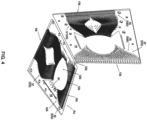
- the planar component 41/43 may be formed from half blocks 48/49 that substantially mirror one another along a plane that divides the planar component 41/43 in half thereby forming two symmetrical halves.
- FIG. 4 only shows one of the two half blocks 48/49.
- the inner surfaces of the blocks of the planar components 41/43 are formed with recesses or cavities that form the inner structure of the planar components 41/43 as will be described below.
- the recesses or cavities on the blocks 41a/43a may be formed by a variety of manufacturing methods known in the art (e.g., computer numerical control (CNC) machining, injection molding, or the like) capable to achieving desired fabrication tolerances.
- CNC computer numerical control
- some curved surfaces i.e., chamfers
- the planar component 41/43 may be made of metals (e.g., aluminum), metallic alloys, thermoplastics, other materials known in the art, or a combination thereof.
- the planar component 41/43 may be made of thermoplastics primarily, and be plated or coated with metals (e.g., gold) or metallic alloys to reduce weight.
- Phased array module 40/42 includes a phase shifting network in the RF front-end device, with the phase shifting network implemented using a Rotman lens 23 ( FIG. 4 ) which may be interposed between the phased array logic (the transmit logic 12 or the receive logic 14) and the array of multiple transmit antennas 22/24, as shown in FIG. 1 .
- the RF front-end device comprises a phase shifting network (implemented as the Rotman lens 23) and a linear antennas array.
- the transmit antennas 22 and/or the receive antennas 24 can be any suitable type of antennas.
- the antennas 22/24 may be a microstrip patch array, Vivaldi antennas, slot coupled patches, horns and others.
- the antennas 22/24 may be microstrip bipodal vivaldi antennas that are fed by the Rotman lens 23.
- the antennas array may be coupled to the array ports of the Rotman lens 23 on a one-to-one basis.
- the Rotman lens 23 includes a cavity space, and a perimeter of the cavity space may include a first side, a second side that is opposite the first side, a third side, and a fourth side that is opposite the third side.
- Input ports or beam ports 50a are located on the first side while output ports or array ports 50b are located on the second side of the cavity space.
- the Rotman lens 23 may be configured such that the beam ports 50a are near the first end 41a/43a of the planar component 41/43 while the array ports 50b are near the second end 41b/43b thereof.
- the electromagnetic waves will be emitted into the cavity space and will reach a corresponding one of array ports 50b.
- the shape of contour with the array ports 50b and the length of waveguides 52, which connect the ends 41a/41b/43a/43b of the planar component 41/43 and the ports 50a/50b, are determined so that, a progressive phase taper is created on the array antennas 22/24 and thus a beam is formed at a particular direction in the space.
- the Rotman lens 23 for the transmit front end device 40a has 63 beam ports and 72 array ports, while the Rotman lens 23 for the receive front end device 42b has 30 beam ports and 72 array ports.
- the front end 10 has an azimuth scanning angle of 50 degrees and an elevation scanning angle of 40 degrees. These values may vary depending on how the Rotman lens 23 is embodied.
- the front end 10 may include 72 transmit antennas and 72 receive antennas where the antennas 22, 24 are equidistantly spaced apart from one another.
- the Rotman lens 23 may serve as a robust and low-cost broadband phase shifting network for the disclosed RF front-end devices 40a/42b and structures.
- active circuitry may be integrated with the beam ports of the Rotman lens, and the lens itself may then be optimized to provide accurate phasing.
- some embodiments may include a Rotman lens 23 with enhanced focusing functionality to provide the phasing with low power loss.
- the third side and the fourth side of the Rotman lens 23 may include dummy ports or sidewall absorbers 50c, 50d, such as radio frequency absorbers, are formed to suppress reflections from the sides of the Rotman lens.
- the radio frequency absorbers may be made of wave absorbing materials such as Eccosorb ® MCS, LS26 or BSR.
- FIGS. 4 and 11 illustrate embodiments of the Rotman lens 23 with jagged sidewall absorbers 50c, 50d.
- Sidewall absorbers 50c, 50d having shapes shown in FIG. 11 may be effective at attenuating the wavefront of the incident pulses.
- the shape of the sidewall absorbers 50c, 50d may include a plurality of sharp triangular "teeth.” As shown in FIG. 14 , these triangular teeth 64 may be formed such that the imaginary lines 62 extending between adjacent vertices of the triangular teeth 64 pointing into the cavity space of the Rotman lens 23, may be oriented to be substantially normal to the curvature of the wavefront. Under such a configuration, a substantial amount of energy may be captured in-between the teeth 64 thereby allowing for an effective dissipation by the sidewall absorbers 50c, 50d, as observable in FIG. 14 .
- the properties of a sidewall absorber 50c/50d may be tested on a fixture 66 a simulated embodiment of which is illustrated in FIG. 12 .
- the properties of a sidewall absorber 50c/50d may be tested on the fixture 66 by feeding a signal into the fixture through its input waveguide port and measuring the reflection coefficient S11 on a Network Analyzer with waveguide millimeter-wave test heads, a simulated embodiment of which is illustrated in FIG. 12 .
- a Network Analyzer with waveguide millimeter-wave test heads a simulated embodiment of which is illustrated in FIG. 12 .
- the Rotman lens 23 can be implemented using waveguides, microstrip, stripline technologies or any combination of the above.
- the Rotman lens may be microstrip-based Rotman lens.
- the Rotman lens 23 may be a waveguide-based Rotman lens. In some cases, waveguides may be used in place of transmission lines.
- the planar component 41/43 further includes waveguides 52 between the first end 41a/43a and the beam ports 50a and between the array ports 50b and the second end 41b/43b.
- the waveguides 52 may be embodied as rectangular waveguides integrated into the planar component 41/43 such that the waveguides 52 form walls that guide the propagation of electromagnetic waves through the planar component 41/43 during transmission or reception of antenna signals from the first end 41a to the second end 41b or vice versa.
- Each of the waveguides 52 may provide a hollow space through which the electromagnetic waves propagate. While FIGS. 5-6 show only one half of the hollow space of the waveguides 52, the hollow space of the half blocks 48/49 may form an enclosed space that extends along the planar component 41/43 and may take on various geometries to affect the polarization of the waves at different locations of the front end device 40a/42b.
- the shape of the cross-section of the hollow space may be described based on a reference rectangular cross-section 54 with a given width in the width directions and a given height in the height directions.
- the waveguide 52 may include a section where the cross-section of the hollow space is as large as the reference rectangular cross-section 54 or smaller than the reference rectangular cross-section 54 as will be described below.
- Each of the waveguides 52 of the Rotman lens 23 may further include a polarization rotator 56 to control the polarization of the waves out of and into the phased array logics.
- FIGS. 5-6 show an example embodiment of the polarization rotator 56 integrated onto the waveguides 52.
- the polarization rotator 56 may include a first section 56a, an iris section 56b, and a second section 56c which are continuously arranged in a longitudinal direction of the planar component 41/43.
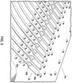
- FIG. 5 shows an inner side of a half block 48 of the transmit planar component 41 where the polarization rotator 56 is formed near the first end 41a.
- the polarization rotator 56 may be similarly formed near the first end 43a of the receive planar component 43.
- the waveguide 52 may include a first set of cuboid obstructions 58a that protrude into the hollow space in opposite height directions such that the height of the cross-section of the first section 56a is less than the given height of the reference rectangular cross-section 54 while the width of the cross-section of the first section 56a may be the same as the given width of the reference rectangular cross-section 54.
- Such height and width may be substantially constant throughout the first section 56a in the longitudinal directions.
- the waveguide 52 may include a diagonal set of cuboid obstructions 58b that protrude into the hollow space from diagonally opposite corners of the reference rectangular cross-section 54 such that an octagonal, cross-sectional area of the iris section 56b is obtained.
- This cross-sectional area of the iris section 56b may be substantially constant throughout the iris section 56b in the longitudinal directions.
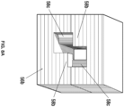
- FIG. 8A shows a cross-section across the iris section 56b of the polarization rotator 56 observed from the viewpoint of the first section 56a such that the second section 56c is visible behind the iris section 56b
- FIG. 8B shows a cross section across the iris section 56b of the polarization rotator 56 observed from the viewpoint of the second section 56c such that first section 56a is visible behind the iris section 56b.
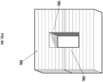
- the waveguide 52 may include a second set of cuboid obstructions 58c that protrude into the hollow space from opposite width directions such that the width of the cross-section of the second section 56c is less than the given width of the reference rectangular cross-section 54 while the height of the cross-section of the second section 56c may be the same as the given height of the reference rectangular cross-section 54 ( FIG. 9A ).
- Such height and width may be substantially constant throughout the second section 56c in the longitudinal directions.
- the iris section 56b can affect different parameters of the radar system.
- the height 60a of the cuboid obstructions 58b in the iris section 56b can be used to tune total effective bandwidth and can affect a balance between bandwidth and central band frequency.
- the length 60b of the cuboid obstructions 58b of the iris section 56b can be used to tune the effective band center.
- the gap 60c of the iris section 56b which is measured between a sidewall of the cuboid obstructions 58b and a sidewall of the second section 56c, can affect both the bandwidth and insertion loss of the polarization rotation.
- the entire length of the polarization rotator that is the combined length of the first section 56a, the iris section 56b, and the second section 56c may be less than 2 ⁇ where ⁇ is equal to a wavelength of the waves traveling through the front end.
- the aforementioned dimensions of the iris section 56b may affect the performance of the antenna which may be described in terms of S-parameters (where SNM represents the power transferred from Port M to Port N in a multi-port network), as shown in the graph of FIG. 13 .
- the dimensions of the iris section 56b may control the locations of a minima of S11 (minimum reflection) and a maxima of S21 (maximum transmission) as well as the beamwidth.
- S11 has a minima of about -31.019899 dB at 78.5 GHz while S21 has a maxima of about - 0.00099132481 dB.
- the process for tuning should be to pick nominal values for the three aforementioned parameters. Nominal values are based on the waveguide 52 selected and are typically 1 ⁇ 4 to 1 times the waveguide long dimension depending on the parameter. Once nominal values are chosen length for the iris section should be tuned to achieve the needed central frequency response. After central frequency response is achieved, the height of the cuboid obstruction 58b should be tuned to get the desired bandwidth and insertion loss. If bandwidth and insertion loss are not achieved, the gap of the iris section 56b can be changed to help insertion loss.
- the gap of the iris section should typically be 30-50% of the long dimension of the waveguide 52. Deviations from this lead to very narrow bandwidths or high insertion loss. Once the desired insertion loss and bandwidth are achieved a re-tune of the length of the iris section will shift the central frequency back to the desired position from the shift due to adjustments to parameters such as the height of the cuboid obstructions 58b and the gap 60c of the iris section 56.
- the waveguides 52 extending between the first end 41a/43a and the beam ports 50a of the Rotman lens 23 may form a first set of waveguides 52a in the transmit planar component 41 and the receive planar component 43.
- Each waveguide in the first set of waveguides 52a may further include one or more polarization rotator(s) 56.
- each waveguide in the first set of waveguides 52a in the transmit planar component 41 and the receive planar component 43 includes a first polarization rotator 56A where the first section 56a of the first polarization rotator 56 is located nearer the first end 41a than the second section 56c thereof.
- each waveguide 52 extending between the second end 41b/43b and the array ports 50b of the Rotman lens 23 in the transmit planar component 41 and in the receive planar component 43 may form a second set of waveguides 52b.
- Each waveguide 52 in the second set of waveguides 52b in the receive planar component 43 may further include one or more polarization rotator 56.
- each waveguide in the second set of waveguides 52b in the receive planar component 43 includes a second polarization rotator 56B which is positioned adjacent the array of antennas 22/24 and in which the first section 56a of the polarization rotators 56 is nearer the second end 43b than the second section 56c thereof.
- the electromagnetic waves propagating through the present apparatus may be in the Transverse Electric (TE) 10 mode.
- the polarization of the waves may be altered by the polarization rotators 56 located throughout the transmit front end device 40a and the receive front end device 42b.
- Waves originating from the transmit logic 12 are polarized to be perpendicular to the plane of the Rotman lens 23 ( FIG. 7B ) but undergo a 90-degree polarization rotation or twist to become polarized parallel to the plane of the Rotman lens ( FIG. 9B ) as the waves propagate through the first polarization rotators 56A of the first set of waveguides 52a of the transmit planar component 41.
- the waves move through the first polarization rotator 56A (i.e., the first section 56a, the iris section 56b and the second section 56c thereof), and the E-plane of the waves is polarized to be parallel to the plane of the Rotman lens 23 of the transmit planar component 41.
- the polarization of the waves may be unchanged by propagation through the rest of the transmit front end device 40a, including the Rotman lens 23, before being transmitted from the transmit antennas 22. If the transmit planar component 41 is oriented to be horizontal about the ground, the polarization of the waves would change from vertical to horizontal in the transmit front end device 40a.
- the linear array of receive antennas 24 is arranged perpendicularly relative to the linear array of transmit antennas 22.
- the receive antennas 24 of the receive front end device 42b may detect the waves that were horizontally polarized and were transmitted by the transmit front end device 40a. The detection of these waves may be improved by the fact that the receive front end device 42b includes two set of polarization rotators 56A, 56B. In other words, the waves arriving at the receive antennas 24 may undergo another 90-degree polarization rotation by the second polarization rotators 56B of the second set of waveguides 52b in the receive planar component 43.
- the waves move through the first section 56a, the iris section 56b and the second section 56c (from FIG. 7B to FIG. 9B ) of the second polarization rotator 56B and are polarized to become parallel the plane of the Rotman lens 23 of the receive planar component 43 (or vertical if the receive planar component 43 is positioned vertically about the ground surface).
- the polarization of these waves may undergo yet another 90-degree polarization rotation at the first polarization rotators 56A of the first set of waveguides 52a of the receive planar component 43.
- the waves move through the second section 56c, the iris section 56b, and the first section 56a (from FIG. 9B to FIG.
- the waves thus reach the receive logic 14 at the same polarization relative to the phased array logic at which the waves were transmitted from the transmit logic 12.
- the first set of waveguides 52a in the transmit planar component 41, the second set of waveguides 52b in the receive planar component 43, and the first set of waveguides 52a in the receive planar component 41 make up the three sets of waveguides 52 that include polarization rotators 56 in the present embodiment of the front end 10.
- the waves undergo three 90-degree polarization rotations or twists during propagation through the transmit front end device 40a and the receive front end device 42b.
- the number of sets of waveguides 52 including polarization rotators 56 may be a different odd number such as one or seven.
- each waveguide in the aforementioned sets of waveguides 52 includes a single polarization rotator 56, it is possible for one waveguide 52 to have more than one polarization rotator 56.
- each of the first set of waveguides 52a extending between the first end 41a and the beam ports 50a in the transmit planar component 41 may include two polarization rotators 56 (e.g., a first polarization rotator 56A and a second polarization rotator 56B in order of wave propagation)
- each of the second set of waveguides 52b extending between the array ports 50b and the second end 41b in the transmit planar component 41 may include one polarization rotator 56 (e.g., a first polarization rotator 56A)
- each the second set of waveguides 52b extending between the second end 43b and the array ports 50b in the receive planar component 43 may include two polarization rotators 56 (e.g., a second polarization rotator 56B and a first
- 90-degree polarization rotation or other expressions relating to rotating the polarization of the waves by “90-degree” or “90 degrees” are meant to include rotation by 270 degrees, 630 degrees, or the like in the opposite rotational direction or rotation by 450 degrees or the like in the same rotational direction as long as the finally reached position can be reached through a rotation by 90 degrees.
- the transmit module 40 and the receive module 42 may be configured in a bi-static manner.
- the bi-static configuration may refer to the working configuration where the receiving module 42 and the transmitting module 40 are separated or not co-located.
- the illustrated example shows that the vertically arranged receive module 42 is configured to be in a receiving mode while the horizontally arranged transmit module 40 is configured to be in a transmission mode.
- the bi-static Tx/Rx configuration of the two phased array modules may be fixed or switchable. In some cases, the vertical receive module 42 and horizontal transmit module 40 can be switched such that the vertical module is the transmitter and the horizontal module is the receiver.
- one or more parameters of the antenna arrays e.g., gain, directivity
- one or more configurations of the Rotman lens or RF absorbers corresponding to one (transmit/receive) front-end device may be different from those of the perpendicularly arranged (receive/transmit) front-end device.
- the front end 10 may feed an array of microstrip patch antennas using microstrip delay-line beamformer.
- the microstrip patch antennas may be fabricated using printed circuit board technologies.
- the patch antennas are resonant antennas fed by a true time delay microstrip beamformer without using a lens.
- An array of Vivaldi antennas may also be connected to the microstrip-based Rotman lens. This may advantageously provide a device with compact and smaller structure, improved accuracy and easy fabrication.
- the patch antennas may be selected (e.g., by selecting patch size and location) such that the patch array operates at the center frequency which is about 78.5 GHz.
- the patch array may comprise 32 patches. Those skilled in the art will appreciate that other number of patches that is smaller than or greater than 32 can be utilized.
Landscapes
- Engineering & Computer Science (AREA)
- Radar, Positioning & Navigation (AREA)
- Remote Sensing (AREA)
- Physics & Mathematics (AREA)
- Computer Networks & Wireless Communication (AREA)
- General Physics & Mathematics (AREA)
- Computer Security & Cryptography (AREA)
- Electromagnetism (AREA)
- Aerials With Secondary Devices (AREA)
- Variable-Direction Aerials And Aerial Arrays (AREA)
Description
- The present disclosure relates to apparatus and methods of detecting objects or obstacles and, more particularly, apparatus and methods of detecting objects or obstacles and recognizing with high accuracy the type of object that.
- A phased array radar system may be a radar system that manipulates the phase of one or more radio waves transmitted by a transmitting and receiving module and uses a pattern of constructive and destructive interference created by the radio waves transmitted with different phases to steer a beam of radio waves in a desired direction.
- In modem radar systems, in order to achieve superior resolution and range, it is desirable to maintain a broad bandwidth with minimal losses throughout the system. Moreover, the growing focus toward imaging radar systems is pushing the frequency range for phased array systems into the millimeter-wave range and beyond. However, achieving a constant progressive phase shift between adjacent antennas over a wide bandwidth is a significant challenge at millimeter-wave frequencies.
-
US 2013/027240 describes a radar system that includes a transmitting assembly, a receiving assembly, a control unit and a signal processing unit. The transmitting assembly receives an input signal and transmits an incident radar signal. The transmitting assembly includes a Rotman lens having a lens cavity, a plurality of beam ports, a plurality of array ports and a patch antenna assembly. The lens cavity has a lens gap between 10 microns to 120 microns. The patch antenna assembly includes a plurality of antenna arrays operable to receive a plurality of time-delayed, in-phase signals from the Rotman lens and to transmit the incident radar signal towards a target. The receiving assembly receives a reflected radar signal and produces an output signal. The signal processing unit compares the input signal to the output signal and implements an algorithm determining the range, velocity and position of the target. - A radar system that comprises a transmit front end device and a receive front end device is defined in
claim 1. - In an illustrative example, a front end device of a radar system comprises a planar component through which electromagnetic waves propagate. The planar component includes a first end, a second end, a cavity space, and a linear array of antennas. The second end located opposite the first end. The cavity space is bounded by beam ports along a first side of the cavity space and by array ports along a second side of the cavity space. The cavity space is in operative communication with the beam ports and with the array ports to form a Rotman lens. The cavity space is further bounded by radio frequency absorbers along a third side and a fourth side of the cavity space. The second side is located opposite the first side, and the fourth side is located opposite the third side. The array of antennas is located along the second end of the planar component. Each of the antennas is in operative communication with a corresponding one of the array ports. The radio frequency absorbers include triangular teeth having vertices, and the triangular teeth are configured such that lines connecting adjacent vertices are substantially normal to a curvature of a wavefront of the waves in the cavity space.
- A method for detecting an object is provided in
claim 15. - A more complete appreciation of the invention and many of the attendant advantages thereof will be readily obtained as the same becomes better understood by reference to the following detailed description when considered in connection with the accompanying drawings, wherein:
-
FIG. 1 shows a schematic representation of an example embodiment of a radar system in accordance with the present disclosure; -
FIG. 2 shows an embodiment of the invention of a front end including a transmit module and a receive module; -
FIG. 3 shows an embodiment of the invention of a transmit planar component and a receive planar component for front end devices of the front end; -
FIG. 4 shows an embodiment of the invention of a half block of the transmit planar component and a half block of the receive planar component where waveguides and a Rotman lens are formed thereon; -
FIG. 5 is a close-up view of an example embodiment of a polarization rotator on the half block of the transmit planar component; -
FIG. 6 is an isolated view of the example polarization rotator including a first section, an iris section and a second section; -
FIG. 7A is a cross-sectional view across the first section of the polarization rotator of a planar component; -
FIG. 7B is a schematic representation of polarization of waves in the first section of the polarization rotator; -
FIG. 8A is a cross-sectional view across the iris section of the polarization rotator of the planar component; -
FIG. 8B is a schematic representation of polarization of waves in the iris section of the polarization rotator; -
FIG. 9A is a cross-sectional view across the second section of the polarization rotator of a planar component; -
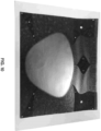
FIG. 9B is a schematic representation of polarization of waves in the second section of the polarization rotator; -
FIG. 10 shows an example embodiment of a front end where a Rotman lens and a transmission lines are formed with microstrips; -
FIG. 11 shows an example embodiment of a half block of a planar component for a front end device including a Rotman lens with sidewall absorbers; -
FIG. 12 shows a computer graphic illustration of an example embodiment of a fixture to test performance of a sidewall absorber; -
FIG. 13 is a graph showing the minimum reflection (S11) and the maximal transmission (S12) for the iris section for given dimensions of the iris section; and -
FIG. 14 is an illustration of reflections around example triangular teeth of sidewall absorbers of the Rotman lens. - Range-finding systems use reflected waves to discern, for example, the presence, distance and/or velocity of objects. Radio Detection And Ranging (radar) and other rangefinding systems have been widely employed in applications, by way of non-limiting example, in autonomous vehicles such as self-driving cars, as well as in wireless communications modems of the type employed, such as in Massive-MIMO (multiple-in-multiple-out) networks, 5G wireless telecommunications, all by way of non-limiting example.
- The radar system may include optimized RF front-end device(s) aiding in achieving higher resolution by improving azimuth resolution, elevation resolution, or any combination thereof. Azimuth resolution is the ability of a radar system to distinguish between objects at similar range but different bearings. Elevation resolution is the ability of a radar system to distinguish between objects at similar range but different elevation. Angular resolution characteristics of a radar are determined by the antenna beam-width represented by the -3 dB angle which is defined by the half-power (-3 dB) points. In some embodiments, radar system or phased array system disclosed herein may have a -3 dB beam-width of 1.5 degree or less in both azimuth resolution and elevation resolution. In particular, the radar system can be configured to achieve finer azimuth resolution and elevation resolution by employing an RF front-end device having two linear antennas arrays arranged perpendicularly and a Rotman lens as a phase shifting network, as will be described below.
-
FIG. 1 shows a schematic illustration of anexample radar system 100 having the abovementioned functionalities. Theradar system 100 may include a millimeter wave radar that emits a low power millimeter wave operating at 76-81 GHz (with a corresponding wavelength of about 4 mm). The radar system can also operate at other frequency range that is below 76 GHz or above 81 GHz. The radar system may comprise any one or more elements of a conventional radar system, a phased array radar system, an AESA (Active Electronically Scanned Array) radar system, a synthetic aperture radar (SAR) system, a MIMO (Multiple-Input Multiple-Output) radar system, and/or a phased-MIMO radar system. - A conventional radar system may be a radar system that uses radio waves transmitted by a transmitting antenna and received by a receiving antenna to detect objects. A phased array radar system may be a radar system that manipulates the phase of one or more radio waves transmitted by a transmitting and receiving module and uses a pattern of constructive and destructive interference created by the radio waves transmitted with different phases to steer a beam of radio waves in a desired direction.
- The
radar system 100 may be provided on a movable object to sense an environment surrounding the movable object. Alternatively, the radar system may be installed on a stationary object. - A movable object can be configured to move within any suitable environment, such as in air (e.g., a fixed-wing aircraft, a rotary-wing aircraft, or an aircraft having neither fixed wings nor rotary wings), in water (e.g., a ship or a submarine), on ground (e.g., a motor vehicle, such as a car, truck, bus, van, motorcycle, bicycle; a movable structure or frame such as a stick, fishing pole; or a train), under the ground (e.g., a subway), in space (e.g., a spaceplane, a satellite, or a probe), or any combination of these environments. The movable object can be a vehicle, such as a vehicle described elsewhere herein. In some embodiments, the movable object can be carried by a living subject, or taken off from a living subject, such as a human or an animal.
- In some cases, the movable object can be an autonomous vehicle which may be referred to as an autonomous car, driverless car, self-driving car, robotic car, or unmanned vehicle. In some cases, an autonomous vehicle may refer to a vehicle configured to sense its environment and navigate or drive with little or no human input. As an example, an autonomous vehicle may be configured to drive to any suitable location and control or perform all safety-critical functions (e.g., driving, steering, braking, parking) for the entire trip, with the driver not expected to control the vehicle at any time. As another example, an autonomous vehicle may allow a driver to safely turn their attention away from driving tasks in particular environments (e.g., on freeways), or an autonomous vehicle may provide control of a vehicle in all but a few environments, requiring little or no input or attention from the driver.
- In some instances, the radar systems may be integrated into a vehicle as part of an autonomous-vehicle driving system. For example, a radar system may provide information about the surrounding environment to a driving system of an autonomous vehicle. An autonomous-vehicle driving system may include one or more computing systems that receive information from a radar system about the surrounding environment, analyze the received information, and provide control signals to the vehicle's driving systems (e.g., steering wheel, accelerator, brake, or turn signal).
- The
radar system 100 that may be used on a vehicle to determine a spatial disposition or physical characteristic of one or more targets in a surrounding environment. The radar system may advantageously have a built-in predictive model for object recognition or highlevel decision making. For example, the predictive model may determine one or more properties of a detected object (e.g., materials, volumetric composition, type, color, etc.) based on radar data. Alternatively or additionally, the predictive model may run on an external system such as the computing system of the vehicle. - The radar system may be mounted to any side of the vehicle, or to one or more sides of the vehicle, e.g. a front side, rear side, lateral side, top side, or bottom side of the vehicle. In some cases, the radar system may be mounted between two adjacent sides of the vehicle. In some cases, the radar system may be mounted to the top of the vehicle. The system may be oriented to detect one or more targets in front of the vehicle, behind the vehicle, or to the lateral sides of the vehicle.
- A target may be any object external to the vehicle. A target may be a living being or an inanimate object. A target may be a pedestrian, an animal, a vehicle, a building, a sign post, a sidewalk, a sidewalk curb, a fence, a tree, or any object that may obstruct a vehicle travelling in any given direction. A target may be stationary, moving, or capable of movement.
- A target object may be located in the front, rear, or lateral side of the vehicle. A target object may be positioned at a range of about 1, 2, 3, 4, 5, 10, 15, 20, 25, 50, 75, or 100 meters from the vehicle. A target may be located on the ground, in the water, or in the air. A target object may be oriented in any direction relative to the vehicle. A target object may be orientated to face the vehicle or oriented to face away from the vehicle at an angle ranging from 0 to 360 degrees.
- A target may have a spatial disposition or characteristic that may be measured or detected. Spatial disposition information may include information about the position, velocity, acceleration, and other kinematic properties of the target relative to the terrestrial vehicle. A characteristic of a target may include information on the size, shape, orientation, volumetric composition, and material properties, such as reflectivity, material composition, of the target or at least a part of the target.
- A surrounding environment may be a location and/or setting in which the vehicle may operate. A surrounding environment may be an indoor or outdoor space. A surrounding environment may be an urban, suburban, or rural setting. A surrounding environment may be a high altitude or low altitude setting. A surrounding environment may include settings that provide poor visibility (night time, heavy precipitation, fog, particulates in the air). A surrounding environment may include targets that are on a travel path of a vehicle. A surrounding environment may include targets that are outside of a travel path of a vehicle. A surrounding environment may be an environment external to a vehicle.
- Referring to
FIG. 1 , in some embodiments, theradar system 100 may comprise a front end in which at least two phased array modules are arranged perpendicularly with each other and the received signals are processed by the correlator of the phased array module. The processed data (e.g., post correlated data) may further be processed by a signal analysis module 101 for object recognition, constructing point cloud image data and other analysis. In some embodiments, a phased array module of thefront end 10 may comprise a transmitlogic 12, receivelogic 14 andcorrelation logic 16 illustrated inFIG. 1 . The phased array module and SERDES may include those described inU.S. Pub. No. 2018/0059215 entitled "Beam-Forming Reconfigurable Correlator (Pulse Compression Receiver) Based on Multi-Gigabit Serial Transceivers (SERDES)". - For example, the transmit
logic 12 may comprise componentry of the type known in the art for use with radar systems (and particularly, for example, in pulse compression radar systems) to transmit into the environment or otherwise a pulse based on an applied analog signal. In the illustrated embodiment, this is shown as including apower amplifier 18,band pass filter 20 and transmitantenna 22, connected as shown or as otherwise known in the art. - The receive
logic 14 comprises componentry of the type known in the art for use with RADAR systems (and particularly, for example, in pulse compression RADAR systems) to receive from the environment (or otherwise) incoming analog signals that represent possible reflections of a transmitted pulse. In point of fact, those signals may often include (or solely constitute) noise. In the illustrated embodiment, the receive logic includes receiveantenna 24, band pass filter 26,low noise amplifier 28, and limitingamplifier 30, connected as shown or as otherwise known in the art. - The
correlation logic 16 correlates the incoming signals, as received and conditioned by the receivelogic 14, with the pulse transmitted by the transmit logic 12 (or, more aptly, in the illustrated embodiment, with the patterns on which that pulse is based) in order to find when, if at all, there is a high correlation between them. Illustrated correlation logic comprises serializer/deserializer (SERDES) 32,correlator 34 andwaveform generator 36, coupled as shown (e.g., by logic gates of an FPGA or otherwise) or as otherwise evident in view of the teachings hereof. -
FIG. 2 illustrates an embodiment of the invention of a front-end apparatus for a millimeter wave radar. A millimeter wave radar may emit a low power millimeter wave operating at 76-81 GHz (with a corresponding wavelength of about 4 mm). The radar system can also operate at other frequency range that is below 76 GHz or above 81 GHz. The radar system may comprise any one or more elements of a conventional radar system, a phased array radar system, an AESA (Active Electronically Scanned Array) radar system, a synthetic aperture radar (SAR) system, a MIMO (Multiple-Input Multiple-Output) radar system, and/or a phased-MIMO radar system. A conventional radar system may be a radar system that uses radio waves transmitted by a transmitting antenna and received by a receiving antenna to detect objects. - As shown in
FIG. 2 , the front-end apparatus may include phased array modules, i.e., a transmitmodule 40 and a receivemodule 42. Each phased array module may include a front end device and a phased array logic. Specifically, the transmit module may include a transmitfront end device 40a and a transmitlogic 12 while the receive module may include a receivefront end device 42b and a receivelogic 14. Each of the transmitfront end device 40a and the receivefront end device 42b includes a planar component such that the transmitfront end device 40a and the receivefront end device 42b include a transmitplanar component 41 and a receiveplanar component 43 respectively.FIG. 3 shows the transmitplanar component 41 and the receiveplanar component 43 in isolation. Moreover, each of theplanar components array logic FIG. 3 ) to accommodate the corresponding phased array logic. - The
planar component 41/43 may be embodied in the form of a rectangular substrate or plate, as shown inFIG. 3 , and includes afirst end 41a/43a and asecond end 41b/43b that are located on opposite longitudinal ends of the rectangular substrate. Thefirst end 41a/43a of theplanar component 41/43 may be operatively connected to the phasedarray logic 12/14 at theslot 44, and thesecond end 41b/43b of theplanar component 41/43 includes a linear array ofantennas 22/24. The phasedarray logic 12/14 may connect to theplanar component 41/43 at theslot 44 forming a right angle near thefirst end 41a/43a. The array of transmitantennas 22 and the array of receiveantennas 24 are perpendicular to one another since the transmitplanar component 41 and the receiveplanar component 43 are arranged to be perpendicular to one another (FIGS. 2-4 ). - The
planar component 41/43 may formed from a split block assembly in that theplanar component 41/43 is formed by assembling a plurality of blocks. For example, theplanar component 41/43 may be formed from half blocks 48/49 that substantially mirror one another along a plane that divides theplanar component 41/43 in half thereby forming two symmetrical halves.FIG. 4 only shows one of the twohalf blocks 48/49. - The inner surfaces of the blocks of the
planar components 41/43 are formed with recesses or cavities that form the inner structure of theplanar components 41/43 as will be described below. The recesses or cavities on theblocks 41a/43a may be formed by a variety of manufacturing methods known in the art (e.g., computer numerical control (CNC) machining, injection molding, or the like) capable to achieving desired fabrication tolerances. As shown inFIGS. 5-6 , some curved surfaces (i.e., chamfers) may remain on theplanar components 41/43 due to the non-zero diameter of the end bit of the CNC milling machine which may be 20 mils, for example. - The
planar component 41/43 may be made of metals (e.g., aluminum), metallic alloys, thermoplastics, other materials known in the art, or a combination thereof. For example, theplanar component 41/43 may be made of thermoplastics primarily, and be plated or coated with metals (e.g., gold) or metallic alloys to reduce weight. -
Phased array module 40/42 includes a phase shifting network in the RF front-end device, with the phase shifting network implemented using a Rotman lens 23 (FIG. 4 ) which may be interposed between the phased array logic (the transmitlogic 12 or the receive logic 14) and the array of multiple transmitantennas 22/24, as shown inFIG. 1 . The RF front-end device comprises a phase shifting network (implemented as the Rotman lens 23) and a linear antennas array. - The transmit
antennas 22 and/or the receiveantennas 24 can be any suitable type of antennas. For example, theantennas 22/24 may be a microstrip patch array, Vivaldi antennas, slot coupled patches, horns and others. In some embodiments, theantennas 22/24 may be microstrip bipodal vivaldi antennas that are fed by theRotman lens 23. For example, the antennas array may be coupled to the array ports of theRotman lens 23 on a one-to-one basis. - The
Rotman lens 23 includes a cavity space, and a perimeter of the cavity space may include a first side, a second side that is opposite the first side, a third side, and a fourth side that is opposite the third side. Input ports orbeam ports 50a are located on the first side while output ports orarray ports 50b are located on the second side of the cavity space. TheRotman lens 23 may be configured such that thebeam ports 50a are near thefirst end 41a/43a of theplanar component 41/43 while thearray ports 50b are near thesecond end 41b/43b thereof. - If one of the
beam ports 50a is excited, the electromagnetic waves will be emitted into the cavity space and will reach a corresponding one ofarray ports 50b. The shape of contour with thearray ports 50b and the length ofwaveguides 52, which connect theends 41a/41b/43a/43b of theplanar component 41/43 and theports 50a/50b, are determined so that, a progressive phase taper is created on thearray antennas 22/24 and thus a beam is formed at a particular direction in the space. - In the present embodiment, the
Rotman lens 23 for the transmitfront end device 40a has 63 beam ports and 72 array ports, while theRotman lens 23 for the receivefront end device 42b has 30 beam ports and 72 array ports. Moreover, thefront end 10 has an azimuth scanning angle of 50 degrees and an elevation scanning angle of 40 degrees. These values may vary depending on how theRotman lens 23 is embodied. Moreover, thefront end 10 may include 72 transmit antennas and 72 receive antennas where theantennas - The
Rotman lens 23 may serve as a robust and low-cost broadband phase shifting network for the disclosed RF front-end devices 40a/42b and structures. In these cases, active circuitry may be integrated with the beam ports of the Rotman lens, and the lens itself may then be optimized to provide accurate phasing. In accordance with another aspect of the disclosure, some embodiments may include aRotman lens 23 with enhanced focusing functionality to provide the phasing with low power loss. - The third side and the fourth side of the
Rotman lens 23 may include dummy ports orsidewall absorbers -
FIGS. 4 and11 illustrate embodiments of theRotman lens 23 withjagged sidewall absorbers Sidewall absorbers FIG. 11 may be effective at attenuating the wavefront of the incident pulses. The shape of thesidewall absorbers FIG. 14 , thesetriangular teeth 64 may be formed such that theimaginary lines 62 extending between adjacent vertices of thetriangular teeth 64 pointing into the cavity space of theRotman lens 23, may be oriented to be substantially normal to the curvature of the wavefront. Under such a configuration, a substantial amount of energy may be captured in-between theteeth 64 thereby allowing for an effective dissipation by thesidewall absorbers FIG. 14 . - The properties of a
sidewall absorber 50c/50d may be tested on a fixture 66 a simulated embodiment of which is illustrated inFIG. 12 . The properties of asidewall absorber 50c/50d may be tested on thefixture 66 by feeding a signal into the fixture through its input waveguide port and measuring the reflection coefficient S11 on a Network Analyzer with waveguide millimeter-wave test heads, a simulated embodiment of which is illustrated inFIG. 12 . Specifically, by emitting waves through theslot 68 towards thetriangular teeth 64 of asidewall absorber 50c/50d secured in a depression of thefixture 66 and measuring the amount of reflection from thetriangular teeth 64, it is possible to test the effectiveness of thesidewall absorber 50c/50d. - As shown in
FIG. 10 , theRotman lens 23 can be implemented using waveguides, microstrip, stripline technologies or any combination of the above. In some embodiments, the Rotman lens may be microstrip-based Rotman lens. In some embodiments, theRotman lens 23 may be a waveguide-based Rotman lens. In some cases, waveguides may be used in place of transmission lines. - In the embodiment of
FIGS. 4-9B , theplanar component 41/43 further includeswaveguides 52 between thefirst end 41a/43a and thebeam ports 50a and between thearray ports 50b and thesecond end 41b/43b. Thewaveguides 52 may be embodied as rectangular waveguides integrated into theplanar component 41/43 such that thewaveguides 52 form walls that guide the propagation of electromagnetic waves through theplanar component 41/43 during transmission or reception of antenna signals from thefirst end 41a to thesecond end 41b or vice versa. - Each of the
waveguides 52 may provide a hollow space through which the electromagnetic waves propagate. WhileFIGS. 5-6 show only one half of the hollow space of thewaveguides 52, the hollow space of the half blocks 48/49 may form an enclosed space that extends along theplanar component 41/43 and may take on various geometries to affect the polarization of the waves at different locations of thefront end device 40a/42b. - Specifically, the shape of the cross-section of the hollow space may be described based on a reference
rectangular cross-section 54 with a given width in the width directions and a given height in the height directions. Thewaveguide 52 may include a section where the cross-section of the hollow space is as large as the referencerectangular cross-section 54 or smaller than the referencerectangular cross-section 54 as will be described below. - Each of the
waveguides 52 of theRotman lens 23 may further include apolarization rotator 56 to control the polarization of the waves out of and into the phased array logics.FIGS. 5-6 show an example embodiment of thepolarization rotator 56 integrated onto thewaveguides 52. Thepolarization rotator 56 may include afirst section 56a, aniris section 56b, and asecond section 56c which are continuously arranged in a longitudinal direction of theplanar component 41/43. -
FIG. 5 shows an inner side of ahalf block 48 of the transmitplanar component 41 where thepolarization rotator 56 is formed near thefirst end 41a. Thepolarization rotator 56 may be similarly formed near thefirst end 43a of the receiveplanar component 43. In thefirst section 56a of the polarization rotator 56 (FIGS. 7A-7B ), thewaveguide 52 may include a first set ofcuboid obstructions 58a that protrude into the hollow space in opposite height directions such that the height of the cross-section of thefirst section 56a is less than the given height of the referencerectangular cross-section 54 while the width of the cross-section of thefirst section 56a may be the same as the given width of the referencerectangular cross-section 54. Such height and width may be substantially constant throughout thefirst section 56a in the longitudinal directions. - In the
iris section 56b of the polarization rotator 56 (FIGS. 8A-8B ), thewaveguide 52 may include a diagonal set ofcuboid obstructions 58b that protrude into the hollow space from diagonally opposite corners of the referencerectangular cross-section 54 such that an octagonal, cross-sectional area of theiris section 56b is obtained. This cross-sectional area of theiris section 56b may be substantially constant throughout theiris section 56b in the longitudinal directions. - It should be noted that
FIG. 8A shows a cross-section across theiris section 56b of thepolarization rotator 56 observed from the viewpoint of thefirst section 56a such that thesecond section 56c is visible behind theiris section 56b whileFIG. 8B shows a cross section across theiris section 56b of thepolarization rotator 56 observed from the viewpoint of thesecond section 56c such thatfirst section 56a is visible behind theiris section 56b. - In the
second section 56c of the polarization rotator 56 (FIGS. 9A-9B ), thewaveguide 52 may include a second set ofcuboid obstructions 58c that protrude into the hollow space from opposite width directions such that the width of the cross-section of thesecond section 56c is less than the given width of the referencerectangular cross-section 54 while the height of the cross-section of thesecond section 56c may be the same as the given height of the reference rectangular cross-section 54 (FIG. 9A ). Such height and width may be substantially constant throughout thesecond section 56c in the longitudinal directions. - Various dimensions of the
iris section 56b (FIG. 6 ) can affect different parameters of the radar system. Theheight 60a of thecuboid obstructions 58b in theiris section 56b can be used to tune total effective bandwidth and can affect a balance between bandwidth and central band frequency. Thelength 60b of thecuboid obstructions 58b of theiris section 56b can be used to tune the effective band center. Thegap 60c of theiris section 56b, which is measured between a sidewall of thecuboid obstructions 58b and a sidewall of thesecond section 56c, can affect both the bandwidth and insertion loss of the polarization rotation. In one example embodiment, theheight 60a of thecuboid obstructions 58b of theiris section 56b, thelength 60b of thecuboid obstructions 58b of theiris section 56b, and thegap 60c of the iris section - 56b may respectively be 0.017 in., 0.094 in., and 0.035 in. Moreover, the entire length of the polarization rotator that is the combined length of the
first section 56a, theiris section 56b, and thesecond section 56c may be less than 2λ where λ is equal to a wavelength of the waves traveling through the front end. - The aforementioned dimensions of the
iris section 56b may affect the performance of the antenna which may be described in terms of S-parameters (where SNM represents the power transferred from Port M to Port N in a multi-port network), as shown in the graph ofFIG. 13 . In one embodiment of theiris section 56, the dimensions of theiris section 56b may control the locations of a minima of S11 (minimum reflection) and a maxima of S21 (maximum transmission) as well as the beamwidth. In the example ofFIG. 13 , S11 has a minima of about -31.019899 dB at 78.5 GHz while S21 has a maxima of about - 0.00099132481 dB. - Due to the complex interaction of the tuning parameters, a systematic tuning approach to getting the needed bandwidth, central frequency and insertion loss are needed when designing the
polarization rotator 56. The process for tuning should be to pick nominal values for the three aforementioned parameters. Nominal values are based on thewaveguide 52 selected and are typically ¼ to 1 times the waveguide long dimension depending on the parameter. Once nominal values are chosen length for the iris section should be tuned to achieve the needed central frequency response. After central frequency response is achieved, the height of thecuboid obstruction 58b should be tuned to get the desired bandwidth and insertion loss. If bandwidth and insertion loss are not achieved, the gap of theiris section 56b can be changed to help insertion loss. The gap of the iris section should typically be 30-50% of the long dimension of thewaveguide 52. Deviations from this lead to very narrow bandwidths or high insertion loss. Once the desired insertion loss and bandwidth are achieved a re-tune of the length of the iris section will shift the central frequency back to the desired position from the shift due to adjustments to parameters such as the height of thecuboid obstructions 58b and thegap 60c of theiris section 56. - As shown in
FIG. 4 , thewaveguides 52 extending between thefirst end 41a/43a and thebeam ports 50a of theRotman lens 23 may form a first set ofwaveguides 52a in the transmitplanar component 41 and the receiveplanar component 43. Each waveguide in the first set ofwaveguides 52a may further include one or more polarization rotator(s) 56. In the present embodiment of thefront end 10, each waveguide in the first set ofwaveguides 52a in the transmitplanar component 41 and the receiveplanar component 43 includes afirst polarization rotator 56A where thefirst section 56a of thefirst polarization rotator 56 is located nearer thefirst end 41a than thesecond section 56c thereof. - As further shown in
FIG. 4 , thewaveguides 52 extending between thesecond end 41b/43b and thearray ports 50b of theRotman lens 23 in the transmitplanar component 41 and in the receiveplanar component 43 may form a second set ofwaveguides 52b. Eachwaveguide 52 in the second set ofwaveguides 52b in the receiveplanar component 43 may further include one ormore polarization rotator 56. In the present embodiment of thefront end 10, each waveguide in the second set ofwaveguides 52b in the receiveplanar component 43 includes asecond polarization rotator 56B which is positioned adjacent the array ofantennas 22/24 and in which thefirst section 56a of thepolarization rotators 56 is nearer thesecond end 43b than thesecond section 56c thereof. - The electromagnetic waves propagating through the present apparatus may be in the Transverse Electric (TE) 10 mode. The polarization of the waves may be altered by the
polarization rotators 56 located throughout the transmitfront end device 40a and the receivefront end device 42b. - Waves originating from the transmit
logic 12 are polarized to be perpendicular to the plane of the Rotman lens 23 (FIG. 7B ) but undergo a 90-degree polarization rotation or twist to become polarized parallel to the plane of the Rotman lens (FIG. 9B ) as the waves propagate through thefirst polarization rotators 56A of the first set ofwaveguides 52a of the transmitplanar component 41. Specifically, the waves move through thefirst polarization rotator 56A (i.e., thefirst section 56a, theiris section 56b and thesecond section 56c thereof), and the E-plane of the waves is polarized to be parallel to the plane of theRotman lens 23 of the transmitplanar component 41. Thereafter, the polarization of the waves may be unchanged by propagation through the rest of the transmitfront end device 40a, including theRotman lens 23, before being transmitted from the transmitantennas 22. If the transmitplanar component 41 is oriented to be horizontal about the ground, the polarization of the waves would change from vertical to horizontal in the transmitfront end device 40a. - As shown in
FIGS. 2-4 , the linear array of receiveantennas 24 is arranged perpendicularly relative to the linear array of transmitantennas 22. Despite this configuration, the receiveantennas 24 of the receivefront end device 42b may detect the waves that were horizontally polarized and were transmitted by the transmitfront end device 40a. The detection of these waves may be improved by the fact that the receivefront end device 42b includes two set ofpolarization rotators antennas 24 may undergo another 90-degree polarization rotation by thesecond polarization rotators 56B of the second set ofwaveguides 52b in the receiveplanar component 43. Specifically, the waves move through thefirst section 56a, theiris section 56b and thesecond section 56c (fromFIG. 7B to FIG. 9B ) of thesecond polarization rotator 56B and are polarized to become parallel the plane of theRotman lens 23 of the receive planar component 43 (or vertical if the receiveplanar component 43 is positioned vertically about the ground surface). After these detected waves propagate through the Rotman lens, the polarization of these waves may undergo yet another 90-degree polarization rotation at thefirst polarization rotators 56A of the first set ofwaveguides 52a of the receiveplanar component 43. Specifically, the waves move through thesecond section 56c, theiris section 56b, and thefirst section 56a (fromFIG. 9B to FIG. 7B ) of thefirst polarization rotators 56A and are polarized to become perpendicular to the plane of theRotman lens 23 of the receiveplanar component 43 12 (i.e., with a horizontal polarization about the ground surface if the receive front end device is perpendicular to the ground surface). The waves thus reach the receivelogic 14 at the same polarization relative to the phased array logic at which the waves were transmitted from the transmitlogic 12. - The first set of
waveguides 52a in the transmitplanar component 41, the second set ofwaveguides 52b in the receiveplanar component 43, and the first set ofwaveguides 52a in the receiveplanar component 41 make up the three sets ofwaveguides 52 that includepolarization rotators 56 in the present embodiment of thefront end 10. Thus, the waves undergo three 90-degree polarization rotations or twists during propagation through the transmitfront end device 40a and the receivefront end device 42b. - However, the number of sets of
waveguides 52 includingpolarization rotators 56 may be a different odd number such as one or seven. In an alternative embodiment of thefront end 10, there could bepolarization rotators 56 in the first set ofwaveguides 52 on the transmitplanar component 41 only and none on the receiveplanar component 43 such that the total number of sets of waveguides includingpolarization rotators 56 is one, for example. - Alternatively, while each waveguide in the aforementioned sets of
waveguides 52 includes asingle polarization rotator 56, it is possible for onewaveguide 52 to have more than onepolarization rotator 56. For example, each of the first set ofwaveguides 52a extending between thefirst end 41a and thebeam ports 50a in the transmitplanar component 41 may include two polarization rotators 56 (e.g., afirst polarization rotator 56A and asecond polarization rotator 56B in order of wave propagation), each of the second set ofwaveguides 52b extending between thearray ports 50b and thesecond end 41b in the transmitplanar component 41 may include one polarization rotator 56 (e.g., afirst polarization rotator 56A), each the second set ofwaveguides 52b extending between thesecond end 43b and thearray ports 50b in the receiveplanar component 43 may include two polarization rotators 56 (e.g., asecond polarization rotator 56B and afirst polarization rotator 56A in order of wave propagation), and each the first set ofwaveguides 52a extending between thebeam ports 50a and thefirst end 43a of the receiveplanar component 43 may include two polarization rotators 56 (e.g., asecond polarization rotator 56B and afirst polarization rotator 56A in order of wave propagation). In such an alternative arrangement of thepolarization rotators 56, there would be a total of seven 90-degree polarization rotations or twists during propagation through the transmitfront end device 40a and the receivefront end device 42b. - The expression "90-degree polarization rotation" or other expressions relating to rotating the polarization of the waves by "90-degree" or "90 degrees" are meant to include rotation by 270 degrees, 630 degrees, or the like in the opposite rotational direction or rotation by 450 degrees or the like in the same rotational direction as long as the finally reached position can be reached through a rotation by 90 degrees.
- In one example arrangement of the
front end 10, the transmitmodule 40 and the receivemodule 42 may be configured in a bi-static manner. The bi-static configuration may refer to the working configuration where the receivingmodule 42 and the transmittingmodule 40 are separated or not co-located. The illustrated example shows that the vertically arranged receivemodule 42 is configured to be in a receiving mode while the horizontally arranged transmitmodule 40 is configured to be in a transmission mode. The bi-static Tx/Rx configuration of the two phased array modules may be fixed or switchable. In some cases, the vertical receivemodule 42 and horizontal transmitmodule 40 can be switched such that the vertical module is the transmitter and the horizontal module is the receiver. - If the radar system is in the bi-static Tx/Rx configuration, one or more parameters of the antenna arrays (e.g., gain, directivity) for the receiving and transmitting may be different. Similarly, one or more configurations of the Rotman lens or RF absorbers corresponding to one (transmit/receive) front-end device may be different from those of the perpendicularly arranged (receive/transmit) front-end device.
- In alternative embodiment (
FIG. 10 ), thefront end 10 may feed an array of microstrip patch antennas using microstrip delay-line beamformer. The microstrip patch antennas may be fabricated using printed circuit board technologies. The patch antennas are resonant antennas fed by a true time delay microstrip beamformer without using a lens. An array of Vivaldi antennas may also be connected to the microstrip-based Rotman lens. This may advantageously provide a device with compact and smaller structure, improved accuracy and easy fabrication. In an example receiving module, the patch antennas may be selected (e.g., by selecting patch size and location) such that the patch array operates at the center frequency which is about 78.5 GHz. In some embodiments, the patch array may comprise 32 patches. Those skilled in the art will appreciate that other number of patches that is smaller than or greater than 32 can be utilized.
Claims (17)
- A front end (10) of a radar system comprising:a transmit front end device (40a) including a transmit planar component (41); anda receive front end device (42b) including a receive planar component (43), each of the transmit planar component and the receive planar component including:a first end (41a, 43a);a second end (41b, 43b) located opposite the first end, electromagnetic waves propagating in propagation directions between the first end and the second end; anda cavity space bounded by beam ports (50a) along a first side of the cavity space and by array ports (50b) along a second side of the cavity space, the cavity space being in operative communication with the beam ports (50a) and with the array ports (50b) to form a Rotman lens (23);characterized in that each of the transmit planar component and the receive planar component also includes
a linear array of antennas (22, 24) located along the second end of the planar component, each of the antennas being in operative communication with a corresponding one of the array ports,wherein the transmit planar component and receive planar component are arranged such that the linear array of antennas (22) of the transmit planar component and the linear array of antennas (24) of the receive planar component are perpendicular to one another. - The front end of claim 1, wherein each of the transmit planar component and the receive planar component further includes a first set of waveguides (52a) that extend between the first end of the planar component and the beam ports and a second set of waveguides (52b) that extend between the array ports and the second end of the planar component, each waveguide of the first set of waveguides and the second set of waveguides including a hollow space inside the waveguide and extending in a longitudinal direction from one end of the waveguide to an opposite end of the waveguide, the hollow space having a reference rectangular cross-section having a given width in width directions and a given height in height directions.
- The front end of claim 2, wherein each waveguide in the first set of waveguides of the transmit planar component includes a first polarization rotator, and each waveguide in the first set of waveguides of the receive planar component includes a first polarization rotator.
- The front end of claim 3, wherein each waveguide in the second set of waveguides of the receive planar component includes a second polarization rotator.
- The front end of claim 4, wherein a number of sets of waveguides with the polarization rotators in the front end is an odd number such that the waves undergo as many 90-degree polarization twists as the odd number during propagation through the transmit front end device and the receive front end device.
- The front end of claim 4, wherein the receive planar component includes two sets of waveguides with the polarization rotators and the transmit planar component includes one set of waveguides with the polarization rotators.
- The front end of claim 4, wherein each of the first polarization rotator (56) and the second polarization rotator (56) includes a first section (56a), an iris section (56b), and a second section (56c) in the longitudinal direction,
wherein the first section includes a first set of cuboid obstructions (58a) that protrude into the hollow space from opposite height directions such that the first section of the hollow space has a first rectangular cross-section with a first height and a first width, the first height is less than the given height, the first width is equal to the given width, and the first height and the first width are substantially constant throughout the first section in the longitudinal direction,wherein the iris section includes a diagonal set of cuboid obstructions (58b) that protrude into the hollow space from diagonally opposite comers of the reference rectangular cross-section such that a cross-sectional area of the iris section of the hollow space is octagonally shaped and is reduced relative to the reference rectangular cross-section, the cross-sectional area of the iris section is substantially constant in the longitudinal direction,wherein the second section includes a second set of cuboid obstructions (58c) that protrude into the hollow space from opposite width directions such that the second section of the hollow space has a second rectangular cross-section in which a second height and a second width, the second width is less than the given width, the second height is equal to the given height, and the second height and the second width are substantially constant throughout the second section in the longitudinal direction, andoptionally wherein waves are rotated by 90 degrees during propagation through the first polarization rotator or the second polarization rotator. - The front end of claim 7, wherein the first section, the iris section and the second section are arranged such that the first section is nearer the first end than the second section in the first polarization rotator, and wherein the first section, the iris section and the second section are arranged such that the first section is nearer the second end than the second section in the second polarization rotator.
- The front end of claim 7, wherein a gap (60c) between one of the cuboid obstructions of the iris section and one of the cuboid obstructions of the second section is 30%-50% of the given width of the reference rectangular cross-section.
- The front end of claim 7, wherein a length of each of the polarization rotator spanning the first section, the iris section, and the second section is less than 2A-, A. being equal to a wavelength of the waves traveling through the front end.
- The front end of claim 1, wherein the transmit front end device includes a transmit logic (12), the receive front end device includes a receive logic (14), and each of the transmit planar component and the receive planar component includes near the first end a slot (44) to operatively connect to a corresponding phased array logic.
- The front end of claim 1, wherein each of the transmit planar component and the receive planar component is formed from a first block (48, 49) and a second block (48, 49), each of the first block and the second block forms a symmetrical half of the hollow space, the first block and the second block are joined along a junction plane which splits a thickness of the planar component in half.
- The front end of claim 1, wherein:i) the waves propagate in a Transverse Electric "TE" 10 mode; orii) the antennas of the transmit front end device and the antennas of the receive front end device are in a bi-static configuration; oriii) the linear array of transmit antennas and the linear array of receive antennas are phased arrays of antennas.
- The front end of a radar system of claim 1, wherein the cavity space is further bounded by radio frequency absorbers (50c, 59d) along a third side and a fourth side of the cavity space, the second side located opposite the first side, the fourth side located opposite the third side,
wherein the radio frequency absorbers include triangular teeth (64) having vertices, and the triangular teeth are configured such that lines connecting adjacent vertices are substantially normal to a curvature of a wavefront of the waves in the cavity space. - A method for detecting an object using a radar system, the method comprising:arranging a transmit front end device (40a) of the radar system including a transmit planar component (41) and a receive front end device (42b) of the radar system including a receive planar component (43) such that a linear array of transmit antennas (22) of the transmit planar component and a linear array of receive antennas (24) of the receive planar component are perpendicular to one another;phase-shifting electromagnetic waves by propagating the waves through a first Rotman lens (23) arranged on the transmit planar component;transmitting the phase-shifted waves through the linear array of transmit antennas; receiving the transmitted waves reflected by the object through the linear array of receive antennas; andpropagating the received waves through a second Rotman lens (23) arranged on the receive planar component.
- The method of claim 15, further comprising:rotating a polarization of the waves to be parallel to a plane of the first Rotman lens (23) prior to the transmitting;rotating the polarization of the received waves to be parallel to a plane of the second Rotman lens; androtating the polarization of the received waves to be perpendicular to the plane of the second Rotman lens.
- The method of claim 15, wherein a change in the polarization of the waves by 90 degrees occurs an odd number of times between the transmitting and the receiving.
Applications Claiming Priority (8)
| Application Number | Priority Date | Filing Date | Title |
|---|---|---|---|
| US202063033023P | 2020-06-01 | 2020-06-01 | |
| US202063032999P | 2020-06-01 | 2020-06-01 | |
| US202063034937P | 2020-06-04 | 2020-06-04 | |
| US202063034675P | 2020-06-04 | 2020-06-04 | |
| US202063034769P | 2020-06-04 | 2020-06-04 | |
| US202063034729P | 2020-06-04 | 2020-06-04 | |
| US202063034751P | 2020-06-04 | 2020-06-04 | |
| PCT/US2021/034178 WO2021247309A1 (en) | 2020-06-01 | 2021-05-26 | Phased array front-end devices |
Publications (3)
| Publication Number | Publication Date |
|---|---|
| EP4158727A1 EP4158727A1 (en) | 2023-04-05 |
| EP4158727A4 EP4158727A4 (en) | 2023-11-29 |
| EP4158727B1 true EP4158727B1 (en) | 2025-02-12 |
Family
ID=78705578
Family Applications (1)
| Application Number | Title | Priority Date | Filing Date |
|---|---|---|---|
| EP21817204.7A Active EP4158727B1 (en) | 2020-06-01 | 2021-05-26 | Phased array front-end devices |
Country Status (3)
| Country | Link |
|---|---|
| US (5) | US11699861B2 (en) |
| EP (1) | EP4158727B1 (en) |
| WO (1) | WO2021247309A1 (en) |
Families Citing this family (7)
| Publication number | Priority date | Publication date | Assignee | Title |
|---|---|---|---|---|
| US11699861B2 (en) * | 2020-06-01 | 2023-07-11 | General Radar Corporation | Perpendicular Rotman phased array front end device |
| US12510627B2 (en) * | 2020-06-17 | 2025-12-30 | Google Llc | Distributed radar system |
| US12506274B2 (en) * | 2022-10-31 | 2025-12-23 | General Radar Corporation | Compact analog beamformers and microwave radar systems containing the same |
| DE102023102084A1 (en) * | 2023-01-27 | 2024-08-01 | Bea Sa | Imaging microwave radar sensor |
| US20260051932A1 (en) * | 2023-04-26 | 2026-02-19 | CesiumAstro, Inc. | Hybrid Digital Delay Beamforming Circuits and Methods |
| US12117517B1 (en) * | 2024-04-18 | 2024-10-15 | Greenerwave | Radar device |
| US12347935B1 (en) * | 2025-02-21 | 2025-07-01 | The Florida International University Board Of Trustees | Dual-band antenna array with stacked rotman lens feed for beamforming |
Family Cites Families (20)
| Publication number | Priority date | Publication date | Assignee | Title |
|---|---|---|---|---|
| US6031501A (en) * | 1997-03-19 | 2000-02-29 | Georgia Tech Research Corporation | Low cost compact electronically scanned millimeter wave lens and method |
| EP1032847B1 (en) * | 1997-11-21 | 2003-04-02 | Raytheon Company | Automotive forward looking sensor |
| US7538740B2 (en) | 2006-03-06 | 2009-05-26 | Alcatel-Lucent Usa Inc. | Multiple-element antenna array for communication network |
| US7728772B2 (en) * | 2006-06-09 | 2010-06-01 | The Regents Of The University Of Michigan | Phased array systems and phased array front-end devices |
| US7724197B1 (en) * | 2007-04-30 | 2010-05-25 | Planet Earth Communications, Llc | Waveguide beam forming lens with per-port power dividers |
| US8022861B2 (en) | 2008-04-04 | 2011-09-20 | Toyota Motor Engineering & Manufacturing North America, Inc. | Dual-band antenna array and RF front-end for mm-wave imager and radar |
| ITRM20080282A1 (en) * | 2008-05-29 | 2009-11-30 | Rf Microtech S R L | SCANNED FLAT ANTENNA. |
| US8248298B2 (en) * | 2008-10-31 | 2012-08-21 | First Rf Corporation | Orthogonal linear transmit receive array radar |
| IT1392314B1 (en) | 2008-12-18 | 2012-02-24 | Space Engineering Spa | ANTENNA A LENS DISCRETE ACTIVE APERIODIC FOR MULTI-DRAFT SATELLITE ROOFS |
| AU2010236234B2 (en) | 2009-04-17 | 2013-07-18 | Raytheon Company | Methods and apparatus for integration of distributed sensors and airport surveillance radar to mitigate blind spots |
| EP2542912A4 (en) | 2010-03-05 | 2014-06-25 | Univ Windsor | RADAR SYSTEM AND METHOD FOR MANUFACTURING THE SAME |
| DE102011083756A1 (en) * | 2011-09-29 | 2013-04-04 | Siemens Ag | Radar apparatus and method for generating a group characteristic of a radar |
| FR3005211B1 (en) * | 2013-04-26 | 2015-05-29 | Thales Sa | DISTRIBUTED POWER DEVICE FOR ANTENNA BEAM FORMATION |
| US9772401B2 (en) | 2014-03-17 | 2017-09-26 | Qualcomm Incorporated | Systems, methods, and apparatus for radar-based detection of objects in a predetermined space |
| DE112017000573B4 (en) | 2016-01-29 | 2024-01-18 | Nidec Corporation | Waveguide device and antenna device with the waveguide device |
| US10746849B2 (en) | 2016-04-08 | 2020-08-18 | General Radar Corp. | Beam-forming reconfigurable correlator (pulse compression receiver) based on multi-gigabit serial transceivers (SERDES) |
| US20180301808A1 (en) * | 2017-04-13 | 2018-10-18 | United States Of America As Represented By Secretary Of The Navy | Large Area Lightweight Electronically Scanned Array |
| US12015195B2 (en) * | 2019-04-30 | 2024-06-18 | Georgia Tech Research Corporation | High gain and large beamwidth Rotman-Lens-based and mm-wave energy harvester systems and associated methods |
| US20230141288A1 (en) | 2020-06-01 | 2023-05-11 | General Radar Corporation | Communication network base station with rotman lens |
| US11699861B2 (en) | 2020-06-01 | 2023-07-11 | General Radar Corporation | Perpendicular Rotman phased array front end device |
-
2020
- 2020-09-20 US US17/026,253 patent/US11699861B2/en active Active
- 2020-10-30 US US17/086,270 patent/US11742591B2/en active Active
-
2021
- 2021-05-26 EP EP21817204.7A patent/EP4158727B1/en active Active
- 2021-05-26 WO PCT/US2021/034178 patent/WO2021247309A1/en not_active Ceased
-
2023
- 2023-01-12 US US18/153,801 patent/US12362500B2/en active Active
- 2023-05-08 US US18/313,537 patent/US20230395993A1/en not_active Abandoned
-
2024
- 2024-11-22 US US18/956,188 patent/US12695213B2/en active Active
Also Published As
| Publication number | Publication date |
|---|---|
| US12362500B2 (en) | 2025-07-15 |
| WO2021247309A1 (en) | 2021-12-09 |
| US11742591B2 (en) | 2023-08-29 |
| EP4158727A1 (en) | 2023-04-05 |
| EP4158727A4 (en) | 2023-11-29 |
| US20230395993A1 (en) | 2023-12-07 |
| US20210373141A1 (en) | 2021-12-02 |
| US20250309562A1 (en) | 2025-10-02 |
| US11699861B2 (en) | 2023-07-11 |
| US12695213B2 (en) | 2026-07-28 |
| US20230170627A1 (en) | 2023-06-01 |
| US20210376486A1 (en) | 2021-12-02 |
Similar Documents
| Publication | Publication Date | Title |
|---|---|---|
| US12362500B2 (en) | Phased array Rotman lens front end devices | |
| US20230141288A1 (en) | Communication network base station with rotman lens | |
| US8248298B2 (en) | Orthogonal linear transmit receive array radar | |
| CN111480263B (en) | Antenna, radar system and method for adjusting polarization of antenna | |
| US20220393341A1 (en) | Two-dimensional radar for millimeter wave applications | |
| EP1471598A1 (en) | Automotive radar | |
| JP2023509575A (en) | Reflect array antenna with two-dimensional beam scanning | |
| US10884118B2 (en) | Radar systems for vehicles and methods for operating radar systems of vehicles | |
| US12506274B2 (en) | Compact analog beamformers and microwave radar systems containing the same | |
| AU2003276259B2 (en) | Common aperture antenna | |
| CN217561727U (en) | Radar and unmanned aerial vehicle | |
| EP4154353B1 (en) | Wave guide for an array antenna | |
| JP2009076986A (en) | Microstrip array antenna and phase monopulse radar device | |
| CN214151046U (en) | Millimeter wave intelligent network security monitoring signal system | |
| Knott et al. | SAR experiments using a conformal antenna array radar demonstrator | |
| Ji et al. | Application of DBF in 77GHz Automotive Millimeter-wave Radar | |
| JPS60119482A (en) | Radar equipment | |
| EP4274027B1 (en) | Waveguide with slot antennas and reflectors | |
| CN110988882B (en) | A 77GHz sparse array automobile anti-collision radar receiving antenna | |
| Nikishov et al. | Ultra-wide scanning topology of the MIMO antenna array for Imaging Radar | |
| JP2026083174A (en) | Antennas and antenna equipment | |
| JP2024088532A (en) | Electronic equipment and transmission/reception system | |
| JP2004150966A (en) | Array antenna |
Legal Events
| Date | Code | Title | Description |
|---|---|---|---|
| STAA | Information on the status of an ep patent application or granted ep patent |
Free format text: STATUS: THE INTERNATIONAL PUBLICATION HAS BEEN MADE |
|
| PUAI | Public reference made under article 153(3) epc to a published international application that has entered the european phase |
Free format text: ORIGINAL CODE: 0009012 |
|
| STAA | Information on the status of an ep patent application or granted ep patent |
Free format text: STATUS: REQUEST FOR EXAMINATION WAS MADE |
|
| 17P | Request for examination filed |
Effective date: 20221207 |
|
| AK | Designated contracting states |
Kind code of ref document: A1 Designated state(s): AL AT BE BG CH CY CZ DE DK EE ES FI FR GB GR HR HU IE IS IT LI LT LU LV MC MK MT NL NO PL PT RO RS SE SI SK SM TR |
|
| DAV | Request for validation of the european patent (deleted) | ||
| DAX | Request for extension of the european patent (deleted) | ||
| REG | Reference to a national code |
Ref country code: DE Ref legal event code: R079 Free format text: PREVIOUS MAIN CLASS: H01Q0003220000 Ipc: G01S0007020000 Ref country code: DE Ref legal event code: R079 Ref document number: 602021026097 Country of ref document: DE Free format text: PREVIOUS MAIN CLASS: H01Q0003220000 Ipc: G01S0007020000 |
|
| A4 | Supplementary search report drawn up and despatched |
Effective date: 20231026 |
|
| RIC1 | Information provided on ipc code assigned before grant |
Ipc: G01S 13/02 20060101ALI20231020BHEP Ipc: H01Q 3/26 20060101ALI20231020BHEP Ipc: G01S 13/00 20060101ALI20231020BHEP Ipc: H01Q 21/24 20060101ALI20231020BHEP Ipc: H01Q 1/32 20060101ALI20231020BHEP Ipc: G01S 13/931 20200101ALI20231020BHEP Ipc: G01S 7/03 20060101ALI20231020BHEP Ipc: G01S 7/02 20060101AFI20231020BHEP |
|
| GRAP | Despatch of communication of intention to grant a patent |
Free format text: ORIGINAL CODE: EPIDOSNIGR1 |
|
| STAA | Information on the status of an ep patent application or granted ep patent |
Free format text: STATUS: GRANT OF PATENT IS INTENDED |
|
| INTG | Intention to grant announced |
Effective date: 20240110 |
|
| GRAJ | Information related to disapproval of communication of intention to grant by the applicant or resumption of examination proceedings by the epo deleted |
Free format text: ORIGINAL CODE: EPIDOSDIGR1 |
|
| STAA | Information on the status of an ep patent application or granted ep patent |
Free format text: STATUS: REQUEST FOR EXAMINATION WAS MADE |
|
| GRAP | Despatch of communication of intention to grant a patent |
Free format text: ORIGINAL CODE: EPIDOSNIGR1 |
|
| STAA | Information on the status of an ep patent application or granted ep patent |
Free format text: STATUS: GRANT OF PATENT IS INTENDED |
|
| INTC | Intention to grant announced (deleted) | ||
| INTG | Intention to grant announced |
Effective date: 20240604 |
|
| GRAS | Grant fee paid |
Free format text: ORIGINAL CODE: EPIDOSNIGR3 |
|
| GRAA | (expected) grant |
Free format text: ORIGINAL CODE: 0009210 |
|
| STAA | Information on the status of an ep patent application or granted ep patent |
Free format text: STATUS: THE PATENT HAS BEEN GRANTED |
|
| AK | Designated contracting states |
Kind code of ref document: B1 Designated state(s): AL AT BE BG CH CY CZ DE DK EE ES FI FR GB GR HR HU IE IS IT LI LT LU LV MC MK MT NL NO PL PT RO RS SE SI SK SM TR |
|
| REG | Reference to a national code |
Ref country code: GB Ref legal event code: FG4D |
|
| REG | Reference to a national code |
Ref country code: CH Ref legal event code: EP |
|
| REG | Reference to a national code |
Ref country code: DE Ref legal event code: R096 Ref document number: 602021026097 Country of ref document: DE |
|
| REG | Reference to a national code |
Ref country code: IE Ref legal event code: FG4D |
|
| REG | Reference to a national code |
Ref country code: NL Ref legal event code: MP Effective date: 20250212 |
|
| PG25 | Lapsed in a contracting state [announced via postgrant information from national office to epo] |
Ref country code: RS Free format text: LAPSE BECAUSE OF FAILURE TO SUBMIT A TRANSLATION OF THE DESCRIPTION OR TO PAY THE FEE WITHIN THE PRESCRIBED TIME-LIMIT Effective date: 20250512 |
|
| PG25 | Lapsed in a contracting state [announced via postgrant information from national office to epo] |
Ref country code: FI Free format text: LAPSE BECAUSE OF FAILURE TO SUBMIT A TRANSLATION OF THE DESCRIPTION OR TO PAY THE FEE WITHIN THE PRESCRIBED TIME-LIMIT Effective date: 20250212 |
|
| PG25 | Lapsed in a contracting state [announced via postgrant information from national office to epo] |
Ref country code: PL Free format text: LAPSE BECAUSE OF FAILURE TO SUBMIT A TRANSLATION OF THE DESCRIPTION OR TO PAY THE FEE WITHIN THE PRESCRIBED TIME-LIMIT Effective date: 20250212 |
|
| PG25 | Lapsed in a contracting state [announced via postgrant information from national office to epo] |
Ref country code: ES Free format text: LAPSE BECAUSE OF FAILURE TO SUBMIT A TRANSLATION OF THE DESCRIPTION OR TO PAY THE FEE WITHIN THE PRESCRIBED TIME-LIMIT Effective date: 20250212 |
|
| REG | Reference to a national code |
Ref country code: LT Ref legal event code: MG9D |
|
| PG25 | Lapsed in a contracting state [announced via postgrant information from national office to epo] |
Ref country code: NO Free format text: LAPSE BECAUSE OF FAILURE TO SUBMIT A TRANSLATION OF THE DESCRIPTION OR TO PAY THE FEE WITHIN THE PRESCRIBED TIME-LIMIT Effective date: 20250512 Ref country code: IS Free format text: LAPSE BECAUSE OF FAILURE TO SUBMIT A TRANSLATION OF THE DESCRIPTION OR TO PAY THE FEE WITHIN THE PRESCRIBED TIME-LIMIT Effective date: 20250612 |
|
| PG25 | Lapsed in a contracting state [announced via postgrant information from national office to epo] |
Ref country code: NL Free format text: LAPSE BECAUSE OF FAILURE TO SUBMIT A TRANSLATION OF THE DESCRIPTION OR TO PAY THE FEE WITHIN THE PRESCRIBED TIME-LIMIT Effective date: 20250212 |
|
| PG25 | Lapsed in a contracting state [announced via postgrant information from national office to epo] |
Ref country code: HR Free format text: LAPSE BECAUSE OF FAILURE TO SUBMIT A TRANSLATION OF THE DESCRIPTION OR TO PAY THE FEE WITHIN THE PRESCRIBED TIME-LIMIT Effective date: 20250212 |
|
| PG25 | Lapsed in a contracting state [announced via postgrant information from national office to epo] |
Ref country code: PT Free format text: LAPSE BECAUSE OF FAILURE TO SUBMIT A TRANSLATION OF THE DESCRIPTION OR TO PAY THE FEE WITHIN THE PRESCRIBED TIME-LIMIT Effective date: 20250612 Ref country code: LV Free format text: LAPSE BECAUSE OF FAILURE TO SUBMIT A TRANSLATION OF THE DESCRIPTION OR TO PAY THE FEE WITHIN THE PRESCRIBED TIME-LIMIT Effective date: 20250212 |
|
| PG25 | Lapsed in a contracting state [announced via postgrant information from national office to epo] |
Ref country code: BG Free format text: LAPSE BECAUSE OF FAILURE TO SUBMIT A TRANSLATION OF THE DESCRIPTION OR TO PAY THE FEE WITHIN THE PRESCRIBED TIME-LIMIT Effective date: 20250212 Ref country code: GR Free format text: LAPSE BECAUSE OF FAILURE TO SUBMIT A TRANSLATION OF THE DESCRIPTION OR TO PAY THE FEE WITHIN THE PRESCRIBED TIME-LIMIT Effective date: 20250513 |
|
| REG | Reference to a national code |
Ref country code: AT Ref legal event code: MK05 Ref document number: 1766529 Country of ref document: AT Kind code of ref document: T Effective date: 20250212 |
|
| PG25 | Lapsed in a contracting state [announced via postgrant information from national office to epo] |
Ref country code: SE Free format text: LAPSE BECAUSE OF FAILURE TO SUBMIT A TRANSLATION OF THE DESCRIPTION OR TO PAY THE FEE WITHIN THE PRESCRIBED TIME-LIMIT Effective date: 20250212 |
|
| PG25 | Lapsed in a contracting state [announced via postgrant information from national office to epo] |
Ref country code: SM Free format text: LAPSE BECAUSE OF FAILURE TO SUBMIT A TRANSLATION OF THE DESCRIPTION OR TO PAY THE FEE WITHIN THE PRESCRIBED TIME-LIMIT Effective date: 20250212 |
|
| PG25 | Lapsed in a contracting state [announced via postgrant information from national office to epo] |
Ref country code: DK Free format text: LAPSE BECAUSE OF FAILURE TO SUBMIT A TRANSLATION OF THE DESCRIPTION OR TO PAY THE FEE WITHIN THE PRESCRIBED TIME-LIMIT Effective date: 20250212 |
|
| PG25 | Lapsed in a contracting state [announced via postgrant information from national office to epo] |
Ref country code: IT Free format text: LAPSE BECAUSE OF FAILURE TO SUBMIT A TRANSLATION OF THE DESCRIPTION OR TO PAY THE FEE WITHIN THE PRESCRIBED TIME-LIMIT Effective date: 20250212 |
|
| PG25 | Lapsed in a contracting state [announced via postgrant information from national office to epo] |
Ref country code: AT Free format text: LAPSE BECAUSE OF FAILURE TO SUBMIT A TRANSLATION OF THE DESCRIPTION OR TO PAY THE FEE WITHIN THE PRESCRIBED TIME-LIMIT Effective date: 20250212 |
|
| PG25 | Lapsed in a contracting state [announced via postgrant information from national office to epo] |
Ref country code: EE Free format text: LAPSE BECAUSE OF FAILURE TO SUBMIT A TRANSLATION OF THE DESCRIPTION OR TO PAY THE FEE WITHIN THE PRESCRIBED TIME-LIMIT Effective date: 20250212 Ref country code: CZ Free format text: LAPSE BECAUSE OF FAILURE TO SUBMIT A TRANSLATION OF THE DESCRIPTION OR TO PAY THE FEE WITHIN THE PRESCRIBED TIME-LIMIT Effective date: 20250212 |
|
| PG25 | Lapsed in a contracting state [announced via postgrant information from national office to epo] |
Ref country code: RO Free format text: LAPSE BECAUSE OF FAILURE TO SUBMIT A TRANSLATION OF THE DESCRIPTION OR TO PAY THE FEE WITHIN THE PRESCRIBED TIME-LIMIT Effective date: 20250212 |
|
| PG25 | Lapsed in a contracting state [announced via postgrant information from national office to epo] |
Ref country code: SK Free format text: LAPSE BECAUSE OF FAILURE TO SUBMIT A TRANSLATION OF THE DESCRIPTION OR TO PAY THE FEE WITHIN THE PRESCRIBED TIME-LIMIT Effective date: 20250212 |
|
| REG | Reference to a national code |
Ref country code: DE Ref legal event code: R097 Ref document number: 602021026097 Country of ref document: DE |
|
| PLBE | No opposition filed within time limit |
Free format text: ORIGINAL CODE: 0009261 |
|
| STAA | Information on the status of an ep patent application or granted ep patent |
Free format text: STATUS: NO OPPOSITION FILED WITHIN TIME LIMIT |
|
| REG | Reference to a national code |
Ref country code: CH Ref legal event code: H13 Free format text: ST27 STATUS EVENT CODE: U-0-0-H10-H13 (AS PROVIDED BY THE NATIONAL OFFICE) Effective date: 20251223 |
|
| REG | Reference to a national code |
Ref country code: CH Ref legal event code: L10 Free format text: ST27 STATUS EVENT CODE: U-0-0-L10-L00 (AS PROVIDED BY THE NATIONAL OFFICE) Effective date: 20251224 |
|
| PG25 | Lapsed in a contracting state [announced via postgrant information from national office to epo] |
Ref country code: LU Free format text: LAPSE BECAUSE OF NON-PAYMENT OF DUE FEES Effective date: 20250526 |
|
| PG25 | Lapsed in a contracting state [announced via postgrant information from national office to epo] |
Ref country code: CH Free format text: LAPSE BECAUSE OF NON-PAYMENT OF DUE FEES Effective date: 20250531 |
|
| 26N | No opposition filed |
Effective date: 20251113 |
|
| REG | Reference to a national code |
Ref country code: BE Ref legal event code: MM Effective date: 20250531 |
|
| PG25 | Lapsed in a contracting state [announced via postgrant information from national office to epo] |
Ref country code: MC Free format text: LAPSE BECAUSE OF FAILURE TO SUBMIT A TRANSLATION OF THE DESCRIPTION OR TO PAY THE FEE WITHIN THE PRESCRIBED TIME-LIMIT Effective date: 20250212 |
|
| PG25 | Lapsed in a contracting state [announced via postgrant information from national office to epo] |
Ref country code: IE Free format text: LAPSE BECAUSE OF NON-PAYMENT OF DUE FEES Effective date: 20250526 |
|
| PG25 | Lapsed in a contracting state [announced via postgrant information from national office to epo] |
Ref country code: BE Free format text: LAPSE BECAUSE OF NON-PAYMENT OF DUE FEES Effective date: 20250531 |
|
| PG25 | Lapsed in a contracting state [announced via postgrant information from national office to epo] |
Ref country code: LT Free format text: LAPSE BECAUSE OF FAILURE TO SUBMIT A TRANSLATION OF THE DESCRIPTION OR TO PAY THE FEE WITHIN THE PRESCRIBED TIME-LIMIT Effective date: 20250212 |
|
| PGFP | Annual fee paid to national office [announced via postgrant information from national office to epo] |
Ref country code: GB Payment date: 20260601 Year of fee payment: 6 |
|
| PGFP | Annual fee paid to national office [announced via postgrant information from national office to epo] |
Ref country code: DE Payment date: 20260602 Year of fee payment: 6 |
|
| PGFP | Annual fee paid to national office [announced via postgrant information from national office to epo] |
Ref country code: FR Payment date: 20260527 Year of fee payment: 6 |
|
| PG25 | Lapsed in a contracting state [announced via postgrant information from national office to epo] |
Ref country code: CY Free format text: LAPSE BECAUSE OF FAILURE TO SUBMIT A TRANSLATION OF THE DESCRIPTION OR TO PAY THE FEE WITHIN THE PRESCRIBED TIME-LIMIT Effective date: 20250212 |