EP4158216B1 - Verfahren und system zum ausrücken einer kupplung während der motorabschaltung und fahrzeug mit einem solchen system - Google Patents
Verfahren und system zum ausrücken einer kupplung während der motorabschaltung und fahrzeug mit einem solchen system Download PDFInfo
- Publication number
- EP4158216B1 EP4158216B1 EP20730590.5A EP20730590A EP4158216B1 EP 4158216 B1 EP4158216 B1 EP 4158216B1 EP 20730590 A EP20730590 A EP 20730590A EP 4158216 B1 EP4158216 B1 EP 4158216B1
- Authority
- EP
- European Patent Office
- Prior art keywords
- engine
- clutch
- transmission
- input shaft
- transmission input
- Prior art date
- Legal status (The legal status is an assumption and is not a legal conclusion. Google has not performed a legal analysis and makes no representation as to the accuracy of the status listed.)
- Active
Links
Images

Classifications
-
- F—MECHANICAL ENGINEERING; LIGHTING; HEATING; WEAPONS; BLASTING
- F16—ENGINEERING ELEMENTS AND UNITS; GENERAL MEASURES FOR PRODUCING AND MAINTAINING EFFECTIVE FUNCTIONING OF MACHINES OR INSTALLATIONS; THERMAL INSULATION IN GENERAL
- F16D—COUPLINGS FOR TRANSMITTING ROTATION; CLUTCHES; BRAKES
- F16D48/00—External control of clutches
- F16D48/06—Control by electric or electronic means, e.g. of fluid pressure
-
- F—MECHANICAL ENGINEERING; LIGHTING; HEATING; WEAPONS; BLASTING
- F16—ENGINEERING ELEMENTS AND UNITS; GENERAL MEASURES FOR PRODUCING AND MAINTAINING EFFECTIVE FUNCTIONING OF MACHINES OR INSTALLATIONS; THERMAL INSULATION IN GENERAL
- F16D—COUPLINGS FOR TRANSMITTING ROTATION; CLUTCHES; BRAKES
- F16D2500/00—External control of clutches by electric or electronic means
- F16D2500/10—System to be controlled
- F16D2500/104—Clutch
- F16D2500/10406—Clutch position
- F16D2500/10412—Transmission line of a vehicle
-
- F—MECHANICAL ENGINEERING; LIGHTING; HEATING; WEAPONS; BLASTING
- F16—ENGINEERING ELEMENTS AND UNITS; GENERAL MEASURES FOR PRODUCING AND MAINTAINING EFFECTIVE FUNCTIONING OF MACHINES OR INSTALLATIONS; THERMAL INSULATION IN GENERAL
- F16D—COUPLINGS FOR TRANSMITTING ROTATION; CLUTCHES; BRAKES
- F16D2500/00—External control of clutches by electric or electronic means
- F16D2500/10—System to be controlled
- F16D2500/108—Gear
- F16D2500/1081—Actuation type
- F16D2500/1083—Automated manual transmission
-
- F—MECHANICAL ENGINEERING; LIGHTING; HEATING; WEAPONS; BLASTING
- F16—ENGINEERING ELEMENTS AND UNITS; GENERAL MEASURES FOR PRODUCING AND MAINTAINING EFFECTIVE FUNCTIONING OF MACHINES OR INSTALLATIONS; THERMAL INSULATION IN GENERAL
- F16D—COUPLINGS FOR TRANSMITTING ROTATION; CLUTCHES; BRAKES
- F16D2500/00—External control of clutches by electric or electronic means
- F16D2500/10—System to be controlled
- F16D2500/11—Application
- F16D2500/1107—Vehicles
- F16D2500/1112—Heavy vehicle
-
- F—MECHANICAL ENGINEERING; LIGHTING; HEATING; WEAPONS; BLASTING
- F16—ENGINEERING ELEMENTS AND UNITS; GENERAL MEASURES FOR PRODUCING AND MAINTAINING EFFECTIVE FUNCTIONING OF MACHINES OR INSTALLATIONS; THERMAL INSULATION IN GENERAL
- F16D—COUPLINGS FOR TRANSMITTING ROTATION; CLUTCHES; BRAKES
- F16D2500/00—External control of clutches by electric or electronic means
- F16D2500/30—Signal inputs
- F16D2500/306—Signal inputs from the engine
- F16D2500/3067—Speed of the engine
-
- F—MECHANICAL ENGINEERING; LIGHTING; HEATING; WEAPONS; BLASTING
- F16—ENGINEERING ELEMENTS AND UNITS; GENERAL MEASURES FOR PRODUCING AND MAINTAINING EFFECTIVE FUNCTIONING OF MACHINES OR INSTALLATIONS; THERMAL INSULATION IN GENERAL
- F16D—COUPLINGS FOR TRANSMITTING ROTATION; CLUTCHES; BRAKES
- F16D2500/00—External control of clutches by electric or electronic means
- F16D2500/30—Signal inputs
- F16D2500/308—Signal inputs from the transmission
- F16D2500/30806—Engaged transmission ratio
- F16D2500/30808—Detection of transmission in neutral
-
- F—MECHANICAL ENGINEERING; LIGHTING; HEATING; WEAPONS; BLASTING
- F16—ENGINEERING ELEMENTS AND UNITS; GENERAL MEASURES FOR PRODUCING AND MAINTAINING EFFECTIVE FUNCTIONING OF MACHINES OR INSTALLATIONS; THERMAL INSULATION IN GENERAL
- F16D—COUPLINGS FOR TRANSMITTING ROTATION; CLUTCHES; BRAKES
- F16D2500/00—External control of clutches by electric or electronic means
- F16D2500/30—Signal inputs
- F16D2500/308—Signal inputs from the transmission
- F16D2500/3081—Signal inputs from the transmission from the input shaft
- F16D2500/30816—Speed of the input shaft
-
- F—MECHANICAL ENGINEERING; LIGHTING; HEATING; WEAPONS; BLASTING
- F16—ENGINEERING ELEMENTS AND UNITS; GENERAL MEASURES FOR PRODUCING AND MAINTAINING EFFECTIVE FUNCTIONING OF MACHINES OR INSTALLATIONS; THERMAL INSULATION IN GENERAL
- F16D—COUPLINGS FOR TRANSMITTING ROTATION; CLUTCHES; BRAKES
- F16D2500/00—External control of clutches by electric or electronic means
- F16D2500/30—Signal inputs
- F16D2500/316—Other signal inputs not covered by the groups above
- F16D2500/3166—Detection of an elapsed period of time
-
- F—MECHANICAL ENGINEERING; LIGHTING; HEATING; WEAPONS; BLASTING
- F16—ENGINEERING ELEMENTS AND UNITS; GENERAL MEASURES FOR PRODUCING AND MAINTAINING EFFECTIVE FUNCTIONING OF MACHINES OR INSTALLATIONS; THERMAL INSULATION IN GENERAL
- F16D—COUPLINGS FOR TRANSMITTING ROTATION; CLUTCHES; BRAKES
- F16D2500/00—External control of clutches by electric or electronic means
- F16D2500/50—Problem to be solved by the control system
- F16D2500/502—Relating the clutch
- F16D2500/50293—Reduction of vibrations
-
- F—MECHANICAL ENGINEERING; LIGHTING; HEATING; WEAPONS; BLASTING
- F16—ENGINEERING ELEMENTS AND UNITS; GENERAL MEASURES FOR PRODUCING AND MAINTAINING EFFECTIVE FUNCTIONING OF MACHINES OR INSTALLATIONS; THERMAL INSULATION IN GENERAL
- F16D—COUPLINGS FOR TRANSMITTING ROTATION; CLUTCHES; BRAKES
- F16D2500/00—External control of clutches by electric or electronic means
- F16D2500/50—Problem to be solved by the control system
- F16D2500/512—Relating to the driver
- F16D2500/5122—Improve passengers comfort
-
- F—MECHANICAL ENGINEERING; LIGHTING; HEATING; WEAPONS; BLASTING
- F16—ENGINEERING ELEMENTS AND UNITS; GENERAL MEASURES FOR PRODUCING AND MAINTAINING EFFECTIVE FUNCTIONING OF MACHINES OR INSTALLATIONS; THERMAL INSULATION IN GENERAL
- F16D—COUPLINGS FOR TRANSMITTING ROTATION; CLUTCHES; BRAKES
- F16D2500/00—External control of clutches by electric or electronic means
- F16D2500/70—Details about the implementation of the control system
- F16D2500/704—Output parameters from the control unit; Target parameters to be controlled
- F16D2500/70402—Actuator parameters
- F16D2500/7041—Position
Definitions
- the present invention relates to a method and system for disengaging a clutch in a transmission of a heavy vehicle before the engine is shut down. This will reduce noise and vibrations.
- Heavy vehicles often comprises an internal combustion engine for the propulsion of the vehicle and can be equipped with an Automated Mechanical Transmission (AMT) having a normally closed clutch, where it is important not to keep the clutch in disengaged position for too long time.
- AMT Automated Mechanical Transmission
- a typical case is when the vehicle is parked with the engine on idle or engine shut off. The reason is to reduce wear on the clutch release bearing. This means that as soon as the driver pulls the parking brake and move the gear lever to neutral, the AMT will be put in neutral and the clutch will be engaged in order to prepare it for a state where it can remain for a long time without any problem.
- An object of the invention is therefore to provide a system for reducing vibrations in a driveline of a vehicle during shut down of an internal combustion engine.
- a further object of the invention is to provide a method for reducing vibrations in a driveline of a vehicle during shut down of an internal combustion engine.
- a further object of the invention is to provide a vehicle comprising such a system.
- An object is also to provide a computer program and a computer program product adapted to perform the steps of the method.
- a system for controlling a clutch in a heavy vehicle comprising an internal combustion engine and an automated mechanical transmission, where the engine is running, the clutch is engaged and the transmission is in neutral
- the system comprising an engine speed sensor, a transmission speed sensor, an electronic control unit adapted to receive a request to shut down the engine, to disengage the clutch of the transmission, and to shut down the engine
- the object of the invention is achieved in that the electronic control unit is adapted to reengage the clutch when the rotation of the engine and the rotation of the transmission input shaft has reached zero, and to actively slow down rotation of the transmission input shaft by the use of a brake device if the stop time for the transmission input shaft exceeds a predefined time interval.
- a method for controlling a clutch in a heavy vehicle where vibrations are reduced in a driveline during shut down of the engine.
- the transmission input shaft of the gearbox is disengaged from the engine during shut down of the engine.
- the vibrations caused by the engine during shut down of the engine are thus not transferred to the transmission, which reduces the vibrations and noise of the driveline.
- the reduction of vibrations and noise will also enhance the quality impression of the vehicle.
- the method is applicable on all automated mechanical transmissions comprising a clutch.
- the gearbox will be in neutral when the engine is shut down, but the input shaft will still be connected to the engine through the engaged clutch. It is further of advantage to keep the clutch engaged as much as possible, in order to reduce wear of the clutch release bearing. Thus, the clutch will normally always be engaged when the gearbox is in neutral.
- the clutch When the request to shut down the engine is issued, the clutch is disengaged. As soon as the engine and the transmission input shaft stops rotating, the clutch will be reengaged again. The rotational speed of the engine and the rotational speed of the transmission input shaft are thus monitored, such that the clutch is not reengaged when one or both are rotating.
- the transmission input shaft may rotate longer than the engine, i.e. the transmission input shaft rotates when the engine has stopped rotating.
- the rotation of the transmission input shaft can be actively reduced by either engaging the clutch slowly and/or partly in order to function as a brake, or by engaging a gearbox brake, e.g. a countershaft brake.
- a gearbox brake e.g. a countershaft brake.
- the clutch is disengaged when the engine speed is below a predefined value.
- the rotational speed of the engine is monitored, and the clutch is disengaged when the rotation of the engine has slowed down some.
- the predefined speed value is below the set idle speed of the engine.
- the set idle speed of a truck may e.g. be in the interval between 600 to 800 rpm, depending e.g. on if a power take off is used, or driver preferences.
- a method for controlling a clutch in a heavy vehicle comprising an internal combustion engine and an automated mechanical transmission, where the engine is running, the clutch is engaged and the transmission is in neutral, the steps of: receiving a request to shut down the engine, disengaging the clutch of the transmission, shutting down the engine, monitoring the rotational speed of the engine, monitoring the rotational speed of the transmission input shaft, if the stop time of the transmission input shaft exceeds a predefined time interval, then actively slow down the transmission input shaft until the rotational speed of the transmission input shaft is zero, and reengaging the clutch completely when the rotational speed of the engine and the rotational speed of the transmission input shaft is zero, are comprised.
- the method is able to reduce vibrations and noise from the driveline caused by the shut down of the engine. If the stop time of the transmission input shaft is longer than a predefined time interval, the transmission input shaft is slowed down actively.
- Fig. 1 shows a schematic heavy vehicle 20 provided with an inventive clutch control system 1.
- vehicle is here a truck, but the clutch control system can be used in any heavy vehicle comprising an internal combustion engine and a transmission having a gearbox with an automated clutch, such as busses or construction equipment.
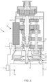
- Fig. 2 shows a schematic clutch control system 1 for a heavy vehicle.
- the clutch control system 1 comprises an internal combustion engine 2 and a transmission 14 comprising a clutch 5 and a gearbox 13.
- the internal combustion engine 2 is provided with a rotational speed sensor (16) adapted to measure the rotational speed e r of the engine.
- the engine is further provided with an electronic control unit (ECU) 3, which is adapted to control various functions of the engine and to communicate with other engine ECU's and the other ECU's of the vehicle.
- the engine is coupled to a transmission 14, and is connected to a gearbox 13 through the clutch 5.
- the pressure plate 15 of the clutch 5 will press the clutch disc 6 against the flywheel 4 of the engine when the clutch is engaged. This will connect the engine with the transmission input shaft 9 of the gearbox 13. The rotation of the engine will be transferred through the gears of the gearbox to a propeller shaft and to the wheels of the vehicle.
- the transmission is provided with a transmission ECU 7 adapted to control the transmission and to communicate with the other ECU's of the vehicle. The transmission ECU will control the clutch and the gear change of the gearbox.
- a transmission actuator 12, which may be a hydraulic actuator, is used to move the pressure plate to and from the clutch disc.
- the engine When the engine is to be shut down, e.g. when a driver wants to park the vehicle, he first stops the vehicle and puts the gearbox in neutral. He may then turn the ignition key or press a stop button, which sends a signal to the engine ECU that the engine is to be shut down. This signal will also be received by the transmission ECU, which disengages the clutch by activating the transmission actuator 12. This disconnects the flywheel of the engine from the transmission input shaft of the transmission. The engine is shut down, e.g. by stopping the fuel supply to the engine. The rotation of the engine will slow down due to internal friction. When the rotation of the engine slows down, there will be some vibrations and some shaking before the rotation stops completely, especially just before the engine stops rotating completely. Since the engine is disconnected from the transmission input shaft, these vibrations are not transferred to the gearbox, which will reduce the overall noise from the vehicle.
- the clutch is disengaged when the engine speed is below a predefined value.
- the rotational speed of the engine is monitored, and the clutch is disengaged when the rotation of the engine has slowed down to a predefined value.
- the predefined speed value is below the set idle speed of the engine.
- the set idle speed of a truck may e.g. be in the interval between 600 to 800 rpm, depending e.g. on if a power take off is used, or on driver preferences.
- a signal may be sent to the transmission ECU that the engine has stopped completely.
- the transmission ECU monitors the rotational speed t r of the transmission input shaft through a transmission speed sensor 8. When the rotational speed t r of the transmission input shaft is also zero, the clutch is reengaged again. This will reduce the wear of the release bearing of the clutch.
- the engine and the transmission input shaft will not rotate for the same time period. In some cases, the engine will rotate for a longer time than the transmission input shaft rotates, e.g. when the transmission is cold. In other cases, the transmission input shaft may rotate for a longer time than the engine rotates, e.g. when the transmission is warm. If the transmission input shaft rotates longer than the engine, and for a time exceeding a predefined time interval t p , the rotation of the transmission input shaft is actively reduced by either engaging the clutch slowly and/or partly in order to function as a brake, or by engaging a gear box brake, e.g. a countershaft brake.
- a gear box brake e.g. a countershaft brake.
- the predefined time interval t p may be selected in dependence of various parameters, such as temperature of the engine and/or the transmission, type of gearbox, idle speed of the engine, actual rotational speed of the transmission input shaft, etc. It is however of advantage to set the predefined time interval to a value such that the stop time for the transmission input shaft is equal to or longer than the stop time of the engine, i.e. that the rotation of the engine stops before the rotation of the transmission.
- the rotation of the engine will stop in a few seconds when the engine is warmed up and the idle speed is relatively low, i.e. no power take-off is used.
- the stop time is thus a few seconds, from the request to shut down the engine to the rotational stop of the engine.
- the stop time for the transmission input shaft may be up to 10 seconds or more when the gearbox is warmed up.
- the predefined time interval for the rotation of the transmission input shaft is in this example set to a time slightly shorter or the same as the stop time for the engine. This will reduce the total time for the disengagement of the clutch.
- the clutch is completely reengaged.
- the stop time for the transmission input shaft exceeds the predefined time interval, the rotation of the transmission input shaft is actively reduced by engaging either the clutch or a gearbox brake.
- the clutch is engaged in a slow manner and/or to some extent in order to reduce noise from the transmission input shaft. It is e.g. preferred to engage the clutch such that the engine does not start to rotate again, i.e. such that the inertia of the non-rotating engine is not overcome.
- the amount of engagement of the clutch can be adjusted, or the predefined time interval can be adjusted.
- gearbox brake If a gearbox brake is used to reduce the rotation of the transmission input shaft, the brake may be engaged in a slow manner in order to reduce noise.
- One type of gearbox brake is a brake acting on the countershaft of the gearbox. Depending on the actual rotational speed of the transmission input shaft, the speed and/or amount of the engagement of the gearbox brake can be adjusted, or the predefined time interval can be adjusted.
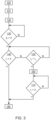
- Fig. 3 shows a schematic flow chart of one example of the method for controlling a clutch in a heavy vehicle comprising an internal combustion engine and a transmission. The method is performed when the engine is shut down. In this example, the engine is warmed up, the rotational speed of the engine is at normal idle speed and the engine will stop rotating before the transmission input shaft. Similar methods may be used for a cold engine/transmission or for other idle speeds.
- an engine ECU receives a request to shut down the engine.
- the request may e.g. come from the driver when the driver turns the ignition key or presses a button, or from an external source.
- the gearbox In order to perform a shut down of the engine, the gearbox must be in neutral.
- the request is received at time t 0 .
- step 110 the clutch of the transmission is disengaged, e.g. by the transmission ECU sending a signal to a clutch actuator that releases the pressure plate of the clutch.
- the engine is now disconnected from the transmission and the transmission input shaft can rotate independently from the engine.
- step 120 the engine is shut down, e.g. by stopping the fuel supply to the engine.
- step 130 the rotational speed of the engine e r is measured and it is determined if the rotational speed is zero. If the rotational speed e r of the engine is not zero, a new measurement is taken until the rotational speed e r is zero, i.e. the engine has stopped rotating. When the engine has stopped rotating, the method continues with step 140.
- step 140 the rotational speed of the transmission input shaft t r is measured and it is determined if the rotational speed t r is zero. If the rotational speed of the transmission input shaft t r is not zero, the method continues with step 150. When the transmission input shaft has stopped rotating, the method continues with step 180.
- step 150 the actual delay time t d is compared with a predefined time interval t p .
- the actual delay time t d is the time measured from t 0 , i.e. from the initialization of the engine shut down. If the delay time t d is less than the predefined time interval t p , a new comparison of the rotational speed of the transmission input shaft is performed in step 140. If the actual delay time t d exceeds the predefined time interval t p , the method continues with step 160.
- step 160 the rotational speed of the transmission input shaft is reduced actively.
- the clutch is used to slow down the transmission input shaft.
- the clutch is engaged in a slow manner and/or partly, such that the rotation of the transmission input shaft is reduced in a controlled manner.
- a gearbox brake is used to slow down the transmission input shaft. The brake is preferably applied in a slow and controlled manner. It is possible to increase the amount of engagement in each iteration, up to a predefined limit.
- step 170 the rotational speed of the transmission input shaft t r is measured and it is determined if the rotational speed is zero. If the rotational speed of the transmission input shaft t r is not zero, a new comparison of the rotational speed of the transmission input shaft is performed. When the transmission input shaft has stopped rotating, the method continues with step 180.
- step 180 the rotation of the engine and the rotation of the transmission input shaft are both zero.
- the clutch can now be reengaged.
- the rotational speed of the engine is monitored, and the clutch is only disengaged when the rotational speed of the engine is below a predefined value.
- the predefined speed value is below the set idle speed of the engine.
- the set idle speed of a truck may e.g. be in the interval between 600 to 800 rpm, depending e.g. on if a power take off is used, or driver preferences.
Landscapes
- Engineering & Computer Science (AREA)
- General Engineering & Computer Science (AREA)
- Physics & Mathematics (AREA)
- Fluid Mechanics (AREA)
- Mechanical Engineering (AREA)
- Hydraulic Clutches, Magnetic Clutches, Fluid Clutches, And Fluid Joints (AREA)
- Control Of Driving Devices And Active Controlling Of Vehicle (AREA)
Claims (15)
- System zum Steuern einer Kupplung (5) in einem schweren Fahrzeug umfassend einen Verbrennungsmotor (2) und ein automatisiertes mechanisches Getriebe (14), wobei der Motor (2) läuft, die Kupplung (5) eingerückt ist und das Getriebe (14) im Leerlauf ist, wobei das System (1) einen Motordrehzahlsensor (16), einen Getriebedrehzahlsensor (8), eine elektronische Steuereinheit (3), die dazu angepasst ist, eine Anfrage zum Abschalten des Motors, zum Ausrücken der Kupplung (5) des Getriebes (14) und zum Abschalten des Motors (2) zu empfangen, umfasst, dadurch gekennzeichnet, dass die elektronische Steuereinheit (3) dazu angepasst ist, die Kupplung (5) erneut einzurücken, wenn die Rotation des Motors (2) und die Rotation der Getriebeeingangswelle (9) Null erreicht haben, und die Rotation der Getriebeeingangswelle (9) durch die Verwendung einer Bremsvorrichtung (5; 11) aktiv zu verlangsamen, wenn die Stoppzeit für die Getriebeeingangswelle (9) einen vorab definierten Zeitraum überschreitet.
- System nach Anspruch 1, dadurch gekennzeichnet, dass die Kupplung (5) des Getriebes (14) ausgerückt wird, wenn die Motordrehzahl unterhalb eines vorab definierten Werts liegt.
- System nach Anspruch 2, dadurch gekennzeichnet, dass der vorab definierte Motordrehzahlwert unterhalb der eingestellten Leerlaufdrehzahl des Motors liegt.
- System nach einem der Ansprüche 1 bis 3, dadurch gekennzeichnet, dass das Getriebe (14) zwei Kupplungen (5) umfasst, die parallel angeordnet sind.
- System nach einem der Ansprüche 1 bis 4, dadurch gekennzeichnet, dass die Bremsvorrichtung die Kupplung (5) ist.
- System nach einem der Ansprüche 1 bis 4, dadurch gekennzeichnet, dass die Bremsvorrichtung eine Getriebebremse (11) ist.
- Verfahren zum Steuern einer Kupplung in einem schweren Fahrzeug umfassend einen Verbrennungsmotor und ein automatisiertes mechanisches Getriebe, wobei der Motor läuft, die Kupplung eingerückt ist und das Getriebe im Leerlauf ist, umfassend die folgenden Schritte:- nach Empfangen einer Anfrage zum Abschalten des Motors,- Ausrücken der Kupplung des Getriebes,- Abschalten des Motors,- Überwachen der Drehzahl des Motors,- Überwachen der Drehzahl der Getriebeeingangswelle,- wenn die Stoppzeit der Getriebeeingangswelle einen vorab definierten Zeitraum überschreitet, dann aktives Verlangsamen der Getriebeeingangswelle, bis die Drehzahl der Getriebeeingangswelle Null ist, und- vollständiges erneutes Einrücken der Kupplung, wenn die Drehzahl des Motors und die Drehzahl der Getriebeeingangswelle Null sind.
- Verfahren nach Anspruch 7, dadurch gekennzeichnet, dass der vorab definierte Zeitraum kürzer als die Stoppzeit des Motors ist.
- Verfahren nach Anspruch 7, dadurch gekennzeichnet, dass der vorab definierte Zeitraum der Stoppzeit des Motors entspricht.
- Verfahren nach einem der Ansprüche 7 bis 9, dadurch gekennzeichnet, dass das Verlangsamen der Getriebeeingangswelle durch die Verwendung der Kupplung erfolgt.
- Verfahren nach einem der Ansprüche 7 bis 9, dadurch gekennzeichnet, dass das Verlangsamen der Getriebeeingangswelle durch die Verwendung einer Getriebebremse erfolgt.
- Verfahren nach einem der Ansprüche 7 bis 11, dadurch gekennzeichnet, dass die Kupplung des Getriebes ausgerückt wird, wenn die Motordrehzahl unterhalb der eingestellten Leerlaufdrehzahl des Motors liegt.
- Fahrzeug, umfassend ein Kupplungssteuersystem nach einem der Ansprüche 1 bis 6.
- Computerprogramm umfassend Programmcodemittel zum Durchführen aller Schritte der Ansprüche 7-12, wenn das Programm auf einem Computer ausgeführt wird.
- Computerprogrammprodukt umfassend Programmcodemittel, die auf einem computerlesbaren Medium gespeichert sind, zum Durchführen aller Schritte der Ansprüche 7-12, wenn das Programmprodukt auf einem Computer ausgeführt wird.
Applications Claiming Priority (1)
| Application Number | Priority Date | Filing Date | Title |
|---|---|---|---|
| PCT/EP2020/065118 WO2021244729A1 (en) | 2020-06-01 | 2020-06-01 | Method and system for disengaging a clutch during engine shutdown and vehicle comprising such a system |
Publications (3)
| Publication Number | Publication Date |
|---|---|
| EP4158216A1 EP4158216A1 (de) | 2023-04-05 |
| EP4158216B1 true EP4158216B1 (de) | 2024-04-10 |
| EP4158216C0 EP4158216C0 (de) | 2024-04-10 |
Family
ID=70977940
Family Applications (1)
| Application Number | Title | Priority Date | Filing Date |
|---|---|---|---|
| EP20730590.5A Active EP4158216B1 (de) | 2020-06-01 | 2020-06-01 | Verfahren und system zum ausrücken einer kupplung während der motorabschaltung und fahrzeug mit einem solchen system |
Country Status (4)
| Country | Link |
|---|---|
| US (1) | US11913505B2 (de) |
| EP (1) | EP4158216B1 (de) |
| CN (1) | CN115667748A (de) |
| WO (1) | WO2021244729A1 (de) |
Families Citing this family (1)
| Publication number | Priority date | Publication date | Assignee | Title |
|---|---|---|---|---|
| CN115306891B (zh) * | 2022-06-30 | 2023-10-20 | 东风汽车集团股份有限公司 | 一种换挡设备的调试方法、控制系统以及存储介质 |
Family Cites Families (14)
| Publication number | Priority date | Publication date | Assignee | Title |
|---|---|---|---|---|
| DE1505402A1 (de) * | 1965-05-20 | 1970-04-02 | Bosch Gmbh Robert | Steuervorrichtung fuer eine hilfskraftbetaetigte Kupplung |
| DE3438594C2 (de) * | 1984-10-20 | 1994-01-20 | Fichtel & Sachs Ag | Kupplungseinrichtung für ein Kraftfahrzeug |
| US5081588A (en) * | 1990-03-26 | 1992-01-14 | Eaton Corporation | Start from stop control method |
| AU2001265764A1 (en) | 2000-05-17 | 2001-11-26 | Luk Lamellen Und Kupplungsbau Beteiligungs Kg | Method and device for automatic actuation of a vehicle brake |
| US7261673B2 (en) | 2002-10-21 | 2007-08-28 | Nissan Diesel Motor Co., Ltd. | Apparatus for controlling automatic transmission |
| WO2008064633A1 (de) * | 2006-11-27 | 2008-06-05 | Luk Lamellen Und Kupplungsbau Beteiligungs Kg | Verfahren und vorrichtung zum adaptieren einer trennkupplung in einem fahrzeughybridantriebsstrang |
| US8066619B2 (en) | 2008-04-19 | 2011-11-29 | Pt Tech, Inc | Clutch control system |
| WO2013137279A1 (ja) | 2012-03-16 | 2013-09-19 | 日産自動車株式会社 | ハイブリッド駆動電気自動車の駆動制御装置及び駆動制御方法 |
| CN203202062U (zh) * | 2013-04-11 | 2013-09-18 | 陕西法士特齿轮有限责任公司 | 重型商用车双离合器变速器用单分离轴承的双离合模块 |
| US9545908B2 (en) | 2014-04-01 | 2017-01-17 | Ford Global Technologies, Llc | Clutch stroke adaptation on engine shutdown |
| EP3179125B1 (de) * | 2014-08-06 | 2019-10-30 | Nissan Motor Co., Ltd | Fahrzeugsteuerungsvorrichtung und fahrzeugsteuerungsverfahren |
| WO2016147841A1 (ja) * | 2015-03-19 | 2016-09-22 | 株式会社小松製作所 | 作業車両、作業車両の監視システム、及び履帯式作業車両 |
| US10899335B2 (en) * | 2016-10-31 | 2021-01-26 | Ford Global Technologies, Llc | Methods and systems for a hybrid vehicle |
| EP3546263B1 (de) * | 2018-03-29 | 2021-07-28 | Volvo Car Corporation | Verfahren und system zum starten eines verbrennungsmotors eines hybridfahrzeugs und hybridfahrzeug mit einem system zum starten eines verbrennungsmotors |
-
2020
- 2020-06-01 EP EP20730590.5A patent/EP4158216B1/de active Active
- 2020-06-01 US US17/928,090 patent/US11913505B2/en active Active
- 2020-06-01 CN CN202080101324.8A patent/CN115667748A/zh active Pending
- 2020-06-01 WO PCT/EP2020/065118 patent/WO2021244729A1/en not_active Ceased
Also Published As
| Publication number | Publication date |
|---|---|
| US20230220888A1 (en) | 2023-07-13 |
| US11913505B2 (en) | 2024-02-27 |
| CN115667748A (zh) | 2023-01-31 |
| WO2021244729A1 (en) | 2021-12-09 |
| EP4158216C0 (de) | 2024-04-10 |
| EP4158216A1 (de) | 2023-04-05 |
Similar Documents
| Publication | Publication Date | Title |
|---|---|---|
| JP3129708B2 (ja) | 内燃機関によって駆動される動力車のための駆動装置 | |
| US6071211A (en) | Idle drive torque control for automated vehicle master clutch | |
| JP4702595B2 (ja) | クラッチ保護システム | |
| EP2689978B1 (de) | Kupplungssteuervorrichtung für ein hybridfahrzeug | |
| US5957805A (en) | Motor vehicle | |
| JPH106818A (ja) | トルク伝達系の制御装置及び方法 | |
| EP1446305B1 (de) | Getriebe für kraftfahrzeuge | |
| EP1151891B1 (de) | Steuerung des Leerlauf-Drehmoments für die automatisierte Trockenfahrkupplung eines Fahrzeugs | |
| EP4158216B1 (de) | Verfahren und system zum ausrücken einer kupplung während der motorabschaltung und fahrzeug mit einem solchen system | |
| US20150046049A1 (en) | Method of operating a transmission | |
| EP2066519B1 (de) | Verfahren zum automatischen ausrücken/einrücken einer kupplungsabhängigen zapfwelle | |
| CN102483108B (zh) | 用于分开离合器的方法和系统 | |
| US7699750B2 (en) | Method for controlling a manual transmission in the event of a disorderly engine behavior | |
| US7270624B2 (en) | Driving unit for motor vehicle and method for determining the characteristic of a coupling of the driving unit | |
| GB2491628A (en) | Inhibiting, delaying or slowing down clutch engagement due to unsuitable vehicle parameters | |
| JPH04116028U (ja) | 車両の機械式電子制御自動変速機 | |
| EP1247014B1 (de) | Verfahren und vorrichtung zum steuern einer brennkraftmaschine sowie brennkraftmaschine | |
| CN110914566B (zh) | 用于在车辆起步时控制动力总成以防止反复熄火的方法 | |
| JP2020133476A (ja) | エンジンの制御装置 | |
| Steinel et al. | Integration of Slip Control for Motor Vehicle Clutch Protection | |
| WO2003089264A1 (en) | Method for controlling a clutch coupling via a brake control and a device for the same | |
| JPS60168951A (ja) | 車輛用無段変速装置 | |
| WO2003076227A1 (en) | Transmission device for motor vehicle |
Legal Events
| Date | Code | Title | Description |
|---|---|---|---|
| STAA | Information on the status of an ep patent application or granted ep patent |
Free format text: STATUS: UNKNOWN |
|
| STAA | Information on the status of an ep patent application or granted ep patent |
Free format text: STATUS: THE INTERNATIONAL PUBLICATION HAS BEEN MADE |
|
| PUAI | Public reference made under article 153(3) epc to a published international application that has entered the european phase |
Free format text: ORIGINAL CODE: 0009012 |
|
| STAA | Information on the status of an ep patent application or granted ep patent |
Free format text: STATUS: REQUEST FOR EXAMINATION WAS MADE |
|
| 17P | Request for examination filed |
Effective date: 20221228 |
|
| AK | Designated contracting states |
Kind code of ref document: A1 Designated state(s): AL AT BE BG CH CY CZ DE DK EE ES FI FR GB GR HR HU IE IS IT LI LT LU LV MC MK MT NL NO PL PT RO RS SE SI SK SM TR |
|
| DAV | Request for validation of the european patent (deleted) | ||
| DAX | Request for extension of the european patent (deleted) | ||
| GRAP | Despatch of communication of intention to grant a patent |
Free format text: ORIGINAL CODE: EPIDOSNIGR1 |
|
| STAA | Information on the status of an ep patent application or granted ep patent |
Free format text: STATUS: GRANT OF PATENT IS INTENDED |
|
| INTG | Intention to grant announced |
Effective date: 20231121 |
|
| GRAS | Grant fee paid |
Free format text: ORIGINAL CODE: EPIDOSNIGR3 |
|
| GRAA | (expected) grant |
Free format text: ORIGINAL CODE: 0009210 |
|
| STAA | Information on the status of an ep patent application or granted ep patent |
Free format text: STATUS: THE PATENT HAS BEEN GRANTED |
|
| AK | Designated contracting states |
Kind code of ref document: B1 Designated state(s): AL AT BE BG CH CY CZ DE DK EE ES FI FR GB GR HR HU IE IS IT LI LT LU LV MC MK MT NL NO PL PT RO RS SE SI SK SM TR |
|
| REG | Reference to a national code |
Ref country code: GB Ref legal event code: FG4D |
|
| RIN1 | Information on inventor provided before grant (corrected) |
Inventor name: KARPENMAN, FREDRIK Inventor name: BLANCKENFIELL, MAGNUS |
|
| REG | Reference to a national code |
Ref country code: CH Ref legal event code: EP |
|
| REG | Reference to a national code |
Ref country code: DE Ref legal event code: R096 Ref document number: 602020028766 Country of ref document: DE |
|
| REG | Reference to a national code |
Ref country code: IE Ref legal event code: FG4D |
|
| U01 | Request for unitary effect filed |
Effective date: 20240502 |
|
| U07 | Unitary effect registered |
Designated state(s): AT BE BG DE DK EE FI FR IT LT LU LV MT NL PT SE SI Effective date: 20240515 |
|
| U20 | Renewal fee for the european patent with unitary effect paid |
Year of fee payment: 5 Effective date: 20240516 |
|
| PG25 | Lapsed in a contracting state [announced via postgrant information from national office to epo] |
Ref country code: IS Free format text: LAPSE BECAUSE OF FAILURE TO SUBMIT A TRANSLATION OF THE DESCRIPTION OR TO PAY THE FEE WITHIN THE PRESCRIBED TIME-LIMIT Effective date: 20240810 |
|
| PG25 | Lapsed in a contracting state [announced via postgrant information from national office to epo] |
Ref country code: HR Free format text: LAPSE BECAUSE OF FAILURE TO SUBMIT A TRANSLATION OF THE DESCRIPTION OR TO PAY THE FEE WITHIN THE PRESCRIBED TIME-LIMIT Effective date: 20240410 |
|
| PG25 | Lapsed in a contracting state [announced via postgrant information from national office to epo] |
Ref country code: GR Free format text: LAPSE BECAUSE OF FAILURE TO SUBMIT A TRANSLATION OF THE DESCRIPTION OR TO PAY THE FEE WITHIN THE PRESCRIBED TIME-LIMIT Effective date: 20240711 |
|
| PG25 | Lapsed in a contracting state [announced via postgrant information from national office to epo] |
Ref country code: ES Free format text: LAPSE BECAUSE OF FAILURE TO SUBMIT A TRANSLATION OF THE DESCRIPTION OR TO PAY THE FEE WITHIN THE PRESCRIBED TIME-LIMIT Effective date: 20240410 |
|
| PG25 | Lapsed in a contracting state [announced via postgrant information from national office to epo] |
Ref country code: PL Free format text: LAPSE BECAUSE OF FAILURE TO SUBMIT A TRANSLATION OF THE DESCRIPTION OR TO PAY THE FEE WITHIN THE PRESCRIBED TIME-LIMIT Effective date: 20240410 |
|
| PG25 | Lapsed in a contracting state [announced via postgrant information from national office to epo] |
Ref country code: PL Free format text: LAPSE BECAUSE OF FAILURE TO SUBMIT A TRANSLATION OF THE DESCRIPTION OR TO PAY THE FEE WITHIN THE PRESCRIBED TIME-LIMIT Effective date: 20240410 Ref country code: NO Free format text: LAPSE BECAUSE OF FAILURE TO SUBMIT A TRANSLATION OF THE DESCRIPTION OR TO PAY THE FEE WITHIN THE PRESCRIBED TIME-LIMIT Effective date: 20240710 Ref country code: IS Free format text: LAPSE BECAUSE OF FAILURE TO SUBMIT A TRANSLATION OF THE DESCRIPTION OR TO PAY THE FEE WITHIN THE PRESCRIBED TIME-LIMIT Effective date: 20240810 Ref country code: HR Free format text: LAPSE BECAUSE OF FAILURE TO SUBMIT A TRANSLATION OF THE DESCRIPTION OR TO PAY THE FEE WITHIN THE PRESCRIBED TIME-LIMIT Effective date: 20240410 Ref country code: GR Free format text: LAPSE BECAUSE OF FAILURE TO SUBMIT A TRANSLATION OF THE DESCRIPTION OR TO PAY THE FEE WITHIN THE PRESCRIBED TIME-LIMIT Effective date: 20240711 Ref country code: ES Free format text: LAPSE BECAUSE OF FAILURE TO SUBMIT A TRANSLATION OF THE DESCRIPTION OR TO PAY THE FEE WITHIN THE PRESCRIBED TIME-LIMIT Effective date: 20240410 Ref country code: RS Free format text: LAPSE BECAUSE OF FAILURE TO SUBMIT A TRANSLATION OF THE DESCRIPTION OR TO PAY THE FEE WITHIN THE PRESCRIBED TIME-LIMIT Effective date: 20240710 |
|
| REG | Reference to a national code |
Ref country code: DE Ref legal event code: R097 Ref document number: 602020028766 Country of ref document: DE |
|
| PG25 | Lapsed in a contracting state [announced via postgrant information from national office to epo] |
Ref country code: CZ Free format text: LAPSE BECAUSE OF FAILURE TO SUBMIT A TRANSLATION OF THE DESCRIPTION OR TO PAY THE FEE WITHIN THE PRESCRIBED TIME-LIMIT Effective date: 20240410 |
|
| PG25 | Lapsed in a contracting state [announced via postgrant information from national office to epo] |
Ref country code: SK Free format text: LAPSE BECAUSE OF FAILURE TO SUBMIT A TRANSLATION OF THE DESCRIPTION OR TO PAY THE FEE WITHIN THE PRESCRIBED TIME-LIMIT Effective date: 20240410 Ref country code: RO Free format text: LAPSE BECAUSE OF FAILURE TO SUBMIT A TRANSLATION OF THE DESCRIPTION OR TO PAY THE FEE WITHIN THE PRESCRIBED TIME-LIMIT Effective date: 20240410 |
|
| PG25 | Lapsed in a contracting state [announced via postgrant information from national office to epo] |
Ref country code: SM Free format text: LAPSE BECAUSE OF FAILURE TO SUBMIT A TRANSLATION OF THE DESCRIPTION OR TO PAY THE FEE WITHIN THE PRESCRIBED TIME-LIMIT Effective date: 20240410 |
|
| PG25 | Lapsed in a contracting state [announced via postgrant information from national office to epo] |
Ref country code: SM Free format text: LAPSE BECAUSE OF FAILURE TO SUBMIT A TRANSLATION OF THE DESCRIPTION OR TO PAY THE FEE WITHIN THE PRESCRIBED TIME-LIMIT Effective date: 20240410 Ref country code: SK Free format text: LAPSE BECAUSE OF FAILURE TO SUBMIT A TRANSLATION OF THE DESCRIPTION OR TO PAY THE FEE WITHIN THE PRESCRIBED TIME-LIMIT Effective date: 20240410 Ref country code: RO Free format text: LAPSE BECAUSE OF FAILURE TO SUBMIT A TRANSLATION OF THE DESCRIPTION OR TO PAY THE FEE WITHIN THE PRESCRIBED TIME-LIMIT Effective date: 20240410 Ref country code: CZ Free format text: LAPSE BECAUSE OF FAILURE TO SUBMIT A TRANSLATION OF THE DESCRIPTION OR TO PAY THE FEE WITHIN THE PRESCRIBED TIME-LIMIT Effective date: 20240410 Ref country code: MC Free format text: LAPSE BECAUSE OF FAILURE TO SUBMIT A TRANSLATION OF THE DESCRIPTION OR TO PAY THE FEE WITHIN THE PRESCRIBED TIME-LIMIT Effective date: 20240410 |
|
| REG | Reference to a national code |
Ref country code: CH Ref legal event code: PL |
|
| PLBE | No opposition filed within time limit |
Free format text: ORIGINAL CODE: 0009261 |
|
| STAA | Information on the status of an ep patent application or granted ep patent |
Free format text: STATUS: NO OPPOSITION FILED WITHIN TIME LIMIT |
|
| 26N | No opposition filed |
Effective date: 20250113 |
|
| GBPC | Gb: european patent ceased through non-payment of renewal fee |
Effective date: 20240710 |
|
| PG25 | Lapsed in a contracting state [announced via postgrant information from national office to epo] |
Ref country code: IE Free format text: LAPSE BECAUSE OF NON-PAYMENT OF DUE FEES Effective date: 20240601 |
|
| PG25 | Lapsed in a contracting state [announced via postgrant information from national office to epo] |
Ref country code: CH Free format text: LAPSE BECAUSE OF NON-PAYMENT OF DUE FEES Effective date: 20240630 |
|
| PG25 | Lapsed in a contracting state [announced via postgrant information from national office to epo] |
Ref country code: GB Free format text: LAPSE BECAUSE OF NON-PAYMENT OF DUE FEES Effective date: 20240710 |
|
| U20 | Renewal fee for the european patent with unitary effect paid |
Year of fee payment: 6 Effective date: 20250624 |
|
| PG25 | Lapsed in a contracting state [announced via postgrant information from national office to epo] |
Ref country code: CY Free format text: LAPSE BECAUSE OF FAILURE TO SUBMIT A TRANSLATION OF THE DESCRIPTION OR TO PAY THE FEE WITHIN THE PRESCRIBED TIME-LIMIT; INVALID AB INITIO Effective date: 20200601 |