EP4158160B1 - Verfahren und system zum betreiben eines gasverdichters in einer ammoniak- und harnstoffanlage - Google Patents
Verfahren und system zum betreiben eines gasverdichters in einer ammoniak- und harnstoffanlage Download PDFInfo
- Publication number
- EP4158160B1 EP4158160B1 EP21726028.0A EP21726028A EP4158160B1 EP 4158160 B1 EP4158160 B1 EP 4158160B1 EP 21726028 A EP21726028 A EP 21726028A EP 4158160 B1 EP4158160 B1 EP 4158160B1
- Authority
- EP
- European Patent Office
- Prior art keywords
- urea
- gas compressor
- producing unit
- steam
- ammonia
- Prior art date
- Legal status (The legal status is an assumption and is not a legal conclusion. Google has not performed a legal analysis and makes no representation as to the accuracy of the status listed.)
- Active
Links
Images
Classifications
-
- F—MECHANICAL ENGINEERING; LIGHTING; HEATING; WEAPONS; BLASTING
- F01—MACHINES OR ENGINES IN GENERAL; ENGINE PLANTS IN GENERAL; STEAM ENGINES
- F01K—STEAM ENGINE PLANTS; STEAM ACCUMULATORS; ENGINE PLANTS NOT OTHERWISE PROVIDED FOR; ENGINES USING SPECIAL WORKING FLUIDS OR CYCLES
- F01K13/00—General layout or general methods of operation of complete plants
-
- C—CHEMISTRY; METALLURGY
- C01—INORGANIC CHEMISTRY
- C01C—AMMONIA; CYANOGEN; COMPOUNDS THEREOF
- C01C1/00—Ammonia; Compounds thereof
- C01C1/02—Preparation, purification or separation of ammonia
- C01C1/04—Preparation of ammonia by synthesis in the gas phase
- C01C1/0405—Preparation of ammonia by synthesis in the gas phase from N2 and H2 in presence of a catalyst
- C01C1/0488—Processes integrated with preparations of other compounds, e.g. methanol, urea or with processes for power generation
-
- C—CHEMISTRY; METALLURGY
- C07—ORGANIC CHEMISTRY
- C07C—ACYCLIC OR CARBOCYCLIC COMPOUNDS
- C07C273/00—Preparation of urea or its derivatives, i.e. compounds containing any of the groups, the nitrogen atoms not being part of nitro or nitroso groups
- C07C273/02—Preparation of urea or its derivatives, i.e. compounds containing any of the groups, the nitrogen atoms not being part of nitro or nitroso groups of urea, its salts, complexes or addition compounds
- C07C273/04—Preparation of urea or its derivatives, i.e. compounds containing any of the groups, the nitrogen atoms not being part of nitro or nitroso groups of urea, its salts, complexes or addition compounds from carbon dioxide and ammonia
-
- F—MECHANICAL ENGINEERING; LIGHTING; HEATING; WEAPONS; BLASTING
- F04—POSITIVE - DISPLACEMENT MACHINES FOR LIQUIDS; PUMPS FOR LIQUIDS OR ELASTIC FLUIDS
- F04D—NON-POSITIVE-DISPLACEMENT PUMPS
- F04D25/00—Pumping installations or systems
- F04D25/02—Units comprising pumps and their driving means
- F04D25/04—Units comprising pumps and their driving means the pump being fluid-driven
-
- F—MECHANICAL ENGINEERING; LIGHTING; HEATING; WEAPONS; BLASTING
- F04—POSITIVE - DISPLACEMENT MACHINES FOR LIQUIDS; PUMPS FOR LIQUIDS OR ELASTIC FLUIDS
- F04D—NON-POSITIVE-DISPLACEMENT PUMPS
- F04D25/00—Pumping installations or systems
- F04D25/02—Units comprising pumps and their driving means
- F04D25/06—Units comprising pumps and their driving means the pump being electrically driven
Definitions
- the present invention is related to the field of urea production.
- a plant comprising an ammonia-producing unit and a urea-producing unit comprising a gas compressor, a steam turbine and an electric motor.
- the present invention provides a method for operating the gas compressor in an ammonia and urea plant.
- Urea is one of the most important chemicals industrially produced today, around 200 million tons of urea is produced worldwide every year. Most of it (above 90% of total production) is used as a fertilizer in agriculture as a nitrogen source. Urea is produced by reacting ammonia (NH 3 ) and carbon dioxide (CO 2 ) in a two-step process: first, two molecules of ammonia react with one molecule of carbon dioxide to form ammonium carbamate (H 2 N-COONH 4 ); secondly, ammonium carbamate decomposes into urea and water.
- NH 3 ammonia
- CO 2 carbon dioxide
- streams of gaseous CO 2 and ammonia are mixed in a synthesis reactor.
- the reaction is carried out at high pressure (above 100 bar) to drive the reaction and increase production rates.
- the stream of CO 2 needs to be compressed under similar pressures before being injected in the synthesis reactor: this step is performed by gas compressors, i.e. a CO 2 compressor.
- a gas compressor requires a great amount of energy to operate and this energy can be supplied by a variety of devices such as turbines and motors.
- a plant comprising a urea-producing unit often also comprises an ammonia-producing unit, since the synthesis of urea requires ammonia.
- An ammonia-producing unit is a net exporter of steam, meaning that it produces more steam than it consumes, and one way to use that steam is to install steam turbines to power the CO 2 compressor of the urea-producing unit and to direct the steam from the ammonia-producing unit to the steam turbine to save cost for the plant.
- the ammonia-producing unit usually does not produce enough steam to fully power the CO 2 compressor.
- the remaining steam required by the compressor may be obtained in different ways, but is often produced by burning a combustible, such as natural gas and coal, and boiling water with the energy released by the combustion in a so-called gas fired boiler.
- the number of boilers is depending by the complexity and required flexibility of the site.
- an ammonia and urea plant refers to a plant comprising one ammonia-producing unit and one urea-producing unit.
- US2018222752A1 discloses processes for production of hydrogen to be used in various industrial processes, including in processes for production of ammonia and urea. Included are polygeneration processes that result in ultra-low emissions.
- a plant comprising an ammonia-producing unit and a urea-producing unit, comprising a gas compressor, a steam turbine fluidly connected to the ammonia-producing unit for receiving steam produced by the ammonia-producing unit, the steam turbine being also connected to the gas compressor, and configured to provide power to the gas compressor during operation of the urea-producing unit, and an electric motor, wherein the electric motor is connected to the gas compressor and configured to provide power to the gas compressor during operation of the urea-producing unit.
- a method for operating a gas compressor in a plant according to the present disclosure comprising the step of providing power from the electric motor to the gas compressor, particularly simultaneously with providing power from the steam turbine to the gas compressor.
- the present invention provides a method for decreasing the steam consumption of a urea-producing unit comprising a gas compressor connected to a steam turbine and configured to receive power from the steam turbine, comprising the steps of installing an electric motor; connecting the electric motor to the gas compressor; providing power from the electric motor to the gas compressor during operation of the urea-producing unit; and simultaneously providing power from the steam turbine to the gas compressor.
- the value to which the modifier "about” refers is itself also specifically disclosed.
- weight percent refers to the relative weight of the respective component based on the overall weight of the formulation.
- the present application discloses a plant comprising an ammonia-producing unit and a urea-producing unit, comprising a gas compressor, a steam turbine fluidly connected to the ammonia-producing unit for receiving steam produced by the ammonia-producing unit, and connected to the gas compressor for providing power to the gas compressor, and an electric motor, wherein the electric motor is connected to the gas compressor and configured to provide power to the gas compressor.
- the present invention provides a plant comprising an ammonia-producing unit and a urea-producing unit, comprising a gas compressor, a steam turbine fluidly connected to the ammonia-producing unit for receiving steam produced by the ammonia-producing unit, the steam turbine being also connected to the gas compressor, and configured to provide power to the gas compressor during operation of the urea-producing unit, and an electric motor, wherein the electric motor is connected to the gas compressor and configured to provide power to the gas compressor during operation of the urea-producing unit.
- the term "during operation" of a unit or plant, in particular of a urea-producing unit refers to the continuous operation mode wherein the unit or plant produces a product, in particular urea.
- a production cycle of a unit or plant comprises a start-up phase, wherein the different processes are initiated, a continuous and essentially constant phase or operation mode, wherein processes operate at a given working load that is usually kept constant during a production cycle; and a shutdown phase, where processes are slowly and safely stopped.
- the present invention describes a plant and a method wherein the steam consumption of the plant during the continuous operation mode, i.e. the second phase as explained above, is reduced.
- Boilers consuming natural gas have long been used in ammonia and urea plants to provide steam required by the different processes in the plant.
- the production of ammonia requires hydrogen gas, which is often produced by steam reforming, a process where natural gas is transformed into hydrogen and carbon dioxide. So, an ammonia and urea plant require the installation to receive and store natural gas in large quantities and adding additional boilers to a plant is seen as a cost-efficient manner to generate additional steam.
- Ammonia and urea plants are often located in natural gas-producing sites to benefit from large supplies of natural gas at competitive prices and are able to use some of that gas to generate steam.
- a urea-producing unit often comprises three steam networks operating at different pressures: a high pressure steam network containing steam between 100 and 120 bar, in particular 110 bar, a medium pressure steam network containing steam between 30 and 50 bar, in particular 40 bar, and a low pressure steam network containing steam between 1 and 5 bar.
- the steam turbine connected to the gas compressor is operating with 40 bar steam.
- the pressure and amount of steam received by the turbine determines the maximum power that the turbine can produce.
- thermal power stations Another source responsible for important emissions of CO 2 are thermal power stations.
- a large number of these power stations uses non-renewable heat sources such as natural gas and/or coal.
- This sector is also trying to reduce its greenhouse footprint and the installation of power stations based on renewable sources such as wind, sunshine and waterfalls, is accelerating worldwide.
- renewable sources such as wind, sunshine and waterfalls
- Both the electric motor and the steam turbine are simultaneously providing power to the gas compressor during operation of the urea-producing unit.
- the amount of power provided by the electric motor and the steam turbine may vary over the course of the production in the urea-producing unit depending on parameters such as steam available in the plant, electricity available in the plant, or the cost of electricity.
- a steam turbine in the urea-producing unit to consume steam produced by other production units, such as an ammonia-producing unit.
- a urea plant also produces steam at lower pressure, for example 4 bar. This lower-pressure steam is used in the urea-producing unit or by other processes which require steam to operate, such as heat exchangers. The steam in excess can be introduced into the steam turbine to provide additional power.
- Electric motors are a well-known class of equipment and can be used to provide power to gas compressors, such as a CO 2 compressor in a urea-producing unit.
- the electric motor may be supplied in electricity from the grid to which the plant is connected to, but it may also be supplied by power stations located within the plant. For example, it may be envisaged to install solar panels and/or wind turbines within the plant to provide the electric motor with electricity.
- renewable energy sources are intermittent, so the electric motor is often connected to the local electricity grid to compensate the irregular electricity production from renewable sources.
- An electric motor to supply power to a gas compressor is particularly beneficial in a country where a major share of the electricity is produced using non-CO 2 emitting sources.
- Renewable sources such as wind, sunshine and waterfalls are non-CO 2 emitting sources.
- Nuclear power plants are not based on a renewable source (uranium); however, they are not emitting CO 2 .
- an electric motor is a device that is able to convert electricity into mechanical power.
- the electric motor is connected to a shaft that transfers the power generated by the electric motor to the gas compressor.
- the electric motor described herein typically does not convert mechanical power back into electricity.
- the electric motor may be sized depending on the power required by the compressor and the loss in power produced by the steam turbine resulting in removing the natural gas boilers or reducing the production rate of the boilers.
- the electric motor is configured to provide 20 to 80% of the power required by the gas compressor. In one embodiment, the electric motor is configured to provide 20 to 50% of the power required by the gas compressor. In one embodiment, the electric motor is configured to provide 50 to 80% of the power required by the gas compressor. In one embodiment, the electric motor is configured to provide 30 to 70% of the power required by the gas compressor. The power to be supplied by the electric motor depends on the amount of steam that should be saved. The more steam that needs to be removed from the plant consumption, the more power the electric motor needs to supply.
- the steam turbine only receives steam from an ammonia-producing unit. It may be that the ammonia-producing unit produces enough steam to be provided to the steam turbine and achieve the required power production by the turbine. In that case, no natural gas boilers are required to produce additional steam. It may also be that the plant comprises a plurality, i.e. more than one, ammonia-producing units and that the plurality of ammonia-producing units all provide steam to the steam turbine of the urea-producing units. When a plant comprises more than one ammonia-producing unit, there is a greater chance that natural boilers are not required to provide steam to the steam turbine of the urea-producing unit.
- the plant comprising an ammonia-producing unit and a urea-producing unit further comprises another steam-producing unit.
- Fertilizer plants may comprise other production units, related or not to fertilizer production. These units may produce steam that is not consumed within the unit and may be directed to a steam turbine in the urea-producing unit.
- the plant comprising an ammonia-producing unit and a urea-producing unit further comprises a nitric acid-producing unit.
- Nitric acid is another important chemical for the production of fertilizers. It is reacted with a base such as ammonia or phosphate rock to produce solid fertilizer compositions. The production of nitric acid requires ammonia, so a plant comprising an ammonia-producing unit may also comprise a nitric acid-producing unit to utilize the ammonia produced in the plant.
- a nitric acid-producing unit comprises a plurality of pieces of equipment such as reactors, heat exchangers and more.
- a nitric acid-producing unit is also a net exporter of steam, which may be provided to the steam turbine of a gas compressor of the urea-producing unit.
- the nitric acid-producing unit is providing steam to the steam turbine connected to a gas compressor of the ammonia and urea plant according to the present disclosure.
- the steam turbine only receives steam from an ammonia-producing unit and a nitric acid-producing unit.
- the gas compressor connected to the electric motor is a carbon dioxide compressor.
- the present invention also discloses a method for operating a gas compressor in a plant, comprising the steps of: providing power from the electric motor to the gas compressor.
- the present invention also discloses a method for operating a gas compressor in a plant according to the present disclosure, particularly during continuous operation of the plant or urea production unit according to the present disclosure, comprising the steps of: providing power from the electric motor to the gas compressor, and simultaneously providing power from the steam turbine to the gas compressor.
- the electric motor may be provided in electricity by local power stations, especially power stations based on renewable energies, and by the national electricity grid.
- the motor allows for the reduction in the natural gas consumption of the plant by providing power to the gas compressor. This method is particularly advantageous in countries where a major share of the electricity is produced using non-CO 2 emitting methods.
- This aspect of the present invention may exhibit the same or similar features and technical effects as the first aspect, i.e. the plant according to the present invention, and vice versa.
- both the electric motor and the steam turbine continuously and simultaneously provide power to the gas compressor.
- the power provided by each unit may vary during a production run.
- the present invention provides a method for decreasing the steam consumption of a urea-producing unit comprising a gas compressor connected to a steam turbine and configured to receive power from the steam turbine, comprising the steps of: installing an electric motor; connecting the electric motor to the gas compressor; providing power from the electric motor to the gas compressor during operations of the urea-producing unit; and simultaneously providing power from the steam turbine to the gas compressor.
- An electric motor is installed and connected to the gas compressor.
- the electric motor is supplied with electricity, that may be generated from renewable energies, such as hydroelectric, wind, solar and tidal, and provides mechanical power to the gas compressor.
- the existing steam turbine does not need to provide as much power to the gas compressor as in prior art systems, i.e. in the absence of the electric motor, so the amount of steam provided to the steam turbine can be decreased.
- steam is usually produced by burning natural gas and heating water with the resulting heat. So decreasing the required amount of steam by the plant or the unit allows to reduce the amount of natural gas burnt to produce steam, and reduces the carbon dioxide emissions caused by the steam production.
- the gas compressor may be a syngas compressor, a carbon dioxide compressor, or an ammonia compressor.
- the ammonia-producing unit supplies steam to the steam turbine of the urea-producing unit.
- the plant comprises a nitric acid-producing unit and the nitric acid-producing unit supplies steam to the steam turbine of the urea-producing unit.
- the present invention provides a method for revamping a plant comprising an ammonia-producing and a urea-producing unit comprising a gas compressor and a steam turbine fluidly connected to the ammonia-producing unit for receiving steam produced by the ammonia-producing unit, connected to the gas compressor for providing power to the gas compressor, and a natural gas boiler connected to the steam turbine.
- the method comprises the steps of: installing an electric motor connected to the gas compressor and configured to provide power to the gas compressor; and optionally, disconnecting the natural gas boiler from the steam turbine.
- This aspect of the present invention may exhibit the same or similar features and technical effects as the first aspect, i.e. the plant according to the present invention, and vice versa.
- the reduction in steam required may only lead to a lower usage rate if the natural gas boilers.
- the boilers instead of operating the boilers at 90% capacity, it may be possible to operate them at less than 80% capacity, in particular less than 70% capacity, thus prolonging their lifetime, and/or facilitating maintenance.
- the electric motor is installed and connected to a carbon dioxide compressor of the urea-producing unit.
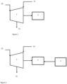
- the urea-producing unit comprises a steam turbine (1) to provide power to the CO 2 compressor (2).
- Figure 1 represents the initial system, i.e. the prior art: the steam turbine received 215 ton/hour (t/h) of 40 bar steam (stream (10)) and produces 19.7 MW of power for the CO 2 compressor. Of the 215 t/h, 145 t/h are produced in the ammonia-producing and the nitric acid-producing units, and 70 t/h are produced by natural gas boilers. Additionally, 18 t/h of 4 bar steam (stream (11)), produced in excess in the urea-producing unit, are injected into the steam turbine, while 138 t/h of 20 bar steam (stream (12)) are extracted from the steam turbine and used into the urea-producing unit.
- stream (11) 4 bar steam
- stream (12) 20 bar steam
- FIG. 2 represents a system according to the present invention.
- An electric motor (3) is installed and connected to the CO 2 compressor (2).
- the electric motor is configured to produce 10.2 MW of power and to supply this power to the CO 2 compressor (2).
- the steam turbine (1) only needs to produce 9.5 MW, so the steam supply is reduced to 175 t/h (stream (13), of which 145 t/h is still produced by the ammonia-producing and nitric acid-producing units.
- stream (13) the steam supply is reduced to 175 t/h (stream (13), of which 145 t/h is still produced by the ammonia-producing and nitric acid-producing units.
- 30 t/h of 40 bar steam instead of 70 t/h, are produced by the natural gas boilers, which is equivalent to 5.4 ton CO 2 equivalent saved per hour.
- the steam turbine still receives 18 t/h of 4 bar steam (stream (14)) and 138 t/h of 20 bar steam (stream 15) is extracted from the turbine
Landscapes
- Engineering & Computer Science (AREA)
- Chemical & Material Sciences (AREA)
- Organic Chemistry (AREA)
- Mechanical Engineering (AREA)
- General Engineering & Computer Science (AREA)
- Combustion & Propulsion (AREA)
- Chemical Kinetics & Catalysis (AREA)
- Analytical Chemistry (AREA)
- Inorganic Chemistry (AREA)
- Engine Equipment That Uses Special Cycles (AREA)
- Structures Of Non-Positive Displacement Pumps (AREA)
- Exhaust Gas After Treatment (AREA)
Claims (9)
- Anlage, umfassend:- eine Ammoniak produzierende Einheit; und- eine Harnstoff produzierende Einheit, umfassend:einen Gasverdichter (2);eine Dampfturbine (1), die mit der Ammoniak produzierenden Einheit fluidverbunden ist, um durch die Ammoniak produzierende Einheit produzierten Dampf zu empfangen, wobei die Dampfturbine (1) mit dem Gasverdichter (2) verbunden und dazu ausgelegt ist, den Gasverdichter (2) während des kontinuierlichen Betriebs der Harnstoff produzierenden Einheit mit Energie zu bereitstellen, wobei es sich um die kontinuierliche Phase in einem Produktionszyklus handelt, in dem die Einheit Harnstoff produziert und mit einer gegebenen Arbeitslast betreibet; undeinen Elektromotor(3);dadurch gekennzeichnet, dass der Elektromotor (3) mit dem Gasverdichter (2) verbunden und dazu ausgelegt ist, den Gasverdichter (2) während des kontinuierlichen Betriebs der Harnstoff produzierenden Einheit mit Energie zu bereitstellen, wobei es sich um die kontinuierliche Phase in einem Produktionszyklus handelt, in dem die Einheit Harnstoff produziert und mit einer gegebenen Arbeitslast betreibet.
- Anlage nach Anspruch 1, wobei der Elektromotor (3) dazu ausgelegt ist, 20 bis 80 % der durch den Gasverdichter (2) benötigten Energie während des kontinuierlichen Betriebs der Harnstoff produzierenden Einheit bereitzustellen, bei dem es sich um die kontinuierliche Phase in einem Produktionszyklus handelt, in dem die Einheit Harnstoff produziert und mit einer gegebenen Arbeitslast betreibet.
- Anlage nach Anspruch 1 oder 2, wobei die Anlage eine Salpetersäure produzierende Einheit umfasst.
- Anlage nach einem der Ansprüche 1 bis 3, wobei der Gasverdichter (2) ein Kohlendioxidverdichter ist.
- Verfahren zum Betreiben eines Gasverdichters (2) in einer Anlage nach einem der Ansprüche 1 bis 4, umfassend den Schritt des Bereitstellens von Energie aus dem Elektromotor (3) an den Gasverdichter (2) während des kontinuierlichen Betriebs der Harnstoff produzierenden Einheit, bei dem es sich um die kontinuierliche Phase in einem Produktionszyklus handelt, in der die Einheit Harnstoff produziert und mit einer gegebenen Arbeitslast betreibet, und des gleichzeitigen Bereitstellens von Energie aus der Dampfturbine (1) an den Gasverdichter (2) .
- Verfahren nach Anspruch 5, umfassend die folgenden Schritte: Installieren des Elektromotors (3); Verbinden des Elektromotors (3) mit dem Gasverdichter (2); Bereitstellen von Energie aus dem Elektromotor (3) an den Gasverdichter (2) während des kontinuierlichen Betriebs der Harnstoff produzierenden Einheit, bei dem es sich um die kontinuierliche Phase in einem Produktionszyklus handelt, in dem die Einheit Harnstoff produziert und mit einer gegebenen Arbeitslast betreibet; und gleichzeitiges Bereitstellen von Energie aus der Dampfturbine (1) an den Gasverdichter (2), wodurch der Dampfverbrauch einer Harnstoff produzierenden Einheit verringert wird, die einen Gasverdichter (2) umfasst, der mit einer Dampfturbine (1) verbunden und dazu ausgelegt ist, Energie aus der Dampfturbine (1) zu empfangen.
- Verfahren nach Anspruch 5 oder 6, wobei die Ammoniak produzierende Einheit Dampf an die Dampfturbine (1) der Harnstoff produzierenden Einheit liefert.
- Verfahren nach einem der Ansprüche 5 bis 7, wobei die Anlage eine Salpetersäure produzierende Einheit umfasst und die Salpetersäure produzierende Einheit Dampf an die Dampfturbine (1) der Harnstoff produzierenden Einheit liefert.
- Verfahren zum Nachrüsten einer Anlage, die eine Ammoniak produzierende und eine Harnstoff produzierende Einheit umfasst, die einen Gasverdichter (2) und eine Dampfturbine (1) umfasst, die mit der Ammoniak produzierenden Einheit fluidverbunden ist, um durch die Ammoniak produzierende Einheit produzierten Dampf zu empfangen, mit dem Gasverdichter (2) zum Bereitstellen von Energie an den Gasverdichter (2) verbunden ist, und einen mit der Dampfturbine (1) verbundenen Erdgasheizkessel, wobei das Verfahren die folgenden Schritte umfasst:- Installieren eines Elektromotors (3), der mit dem Gasverdichter (2) verbunden und dazu ausgelegt ist, den Gasverdichter (2) während des kontinuierlichen Betriebs der Harnstoff produzierenden Einheit mit Energie zu bereitstellen, bei dem es sich um die kontinuierliche Phase in einem Produktionszyklus ist, in dem die Einheit Harnstoff produziert und mit einer gegebenen Arbeitslast betreibet.- optionales Trennen des Erdgasheizkessels von der Dampfturbine (1).
Applications Claiming Priority (2)
| Application Number | Priority Date | Filing Date | Title |
|---|---|---|---|
| EP20176605.2A EP3916206A1 (de) | 2020-05-26 | 2020-05-26 | Verfahren und system zum betreiben eines gasverdichters in einer ammoniak- und harnstoffanlage |
| PCT/EP2021/063975 WO2021239775A1 (en) | 2020-05-26 | 2021-05-26 | Method and system for operating a gas compressor in an ammonia and urea plant |
Publications (3)
| Publication Number | Publication Date |
|---|---|
| EP4158160A1 EP4158160A1 (de) | 2023-04-05 |
| EP4158160B1 true EP4158160B1 (de) | 2024-08-14 |
| EP4158160C0 EP4158160C0 (de) | 2024-08-14 |
Family
ID=70861217
Family Applications (2)
| Application Number | Title | Priority Date | Filing Date |
|---|---|---|---|
| EP20176605.2A Withdrawn EP3916206A1 (de) | 2020-05-26 | 2020-05-26 | Verfahren und system zum betreiben eines gasverdichters in einer ammoniak- und harnstoffanlage |
| EP21726028.0A Active EP4158160B1 (de) | 2020-05-26 | 2021-05-26 | Verfahren und system zum betreiben eines gasverdichters in einer ammoniak- und harnstoffanlage |
Family Applications Before (1)
| Application Number | Title | Priority Date | Filing Date |
|---|---|---|---|
| EP20176605.2A Withdrawn EP3916206A1 (de) | 2020-05-26 | 2020-05-26 | Verfahren und system zum betreiben eines gasverdichters in einer ammoniak- und harnstoffanlage |
Country Status (7)
| Country | Link |
|---|---|
| US (1) | US12404783B2 (de) |
| EP (2) | EP3916206A1 (de) |
| CN (1) | CN115485460B (de) |
| CA (1) | CA3180125A1 (de) |
| PL (1) | PL4158160T3 (de) |
| SA (1) | SA522441449B1 (de) |
| WO (1) | WO2021239775A1 (de) |
Families Citing this family (1)
| Publication number | Priority date | Publication date | Assignee | Title |
|---|---|---|---|---|
| EP4385970A1 (de) * | 2022-12-13 | 2024-06-19 | Yara International ASA | Harnstoffproduzierende anlage mit niedrigen kohlendioxidemissionen |
Citations (4)
| Publication number | Priority date | Publication date | Assignee | Title |
|---|---|---|---|---|
| WO2015193108A1 (en) | 2014-06-18 | 2015-12-23 | Casale Sa | Process for production of ammonia and derivatives, in particular urea |
| WO2018052304A1 (en) | 2016-09-19 | 2018-03-22 | Stamicarbon B.V. | Plant and process for producing nitric acid |
| US20180222752A1 (en) | 2015-12-04 | 2018-08-09 | Grannus Llc | Polygeneration production of hydrogen for use in various industrial processes |
| WO2020104197A1 (en) | 2018-11-22 | 2020-05-28 | Casale Sa | A process for the synthesis of urea |
Family Cites Families (18)
| Publication number | Priority date | Publication date | Assignee | Title |
|---|---|---|---|---|
| JPS61133404A (ja) * | 1984-12-03 | 1986-06-20 | Toshiba Corp | コンプレツサの最適運転方法 |
| JP2001074334A (ja) * | 1999-09-03 | 2001-03-23 | Daikin Ind Ltd | 冷凍装置 |
| NO326272B1 (no) * | 2004-07-01 | 2008-10-27 | Yara Int Asa | Fremgangsmate for produksjon av gjodningsmiddel som inneholder urea og ammoniumsulfat |
| JP4240155B1 (ja) * | 2008-03-06 | 2009-03-18 | 三浦工業株式会社 | 蒸気システム |
| WO2010142574A2 (de) * | 2009-06-09 | 2010-12-16 | Siemens Aktiengesellschaft | Anordnung zur verflüssigung von erdgas und verfahren zum anfahren der anordnung |
| RU2440977C1 (ru) | 2010-10-11 | 2012-01-27 | Открытое Акционерное Общество "Научно-Исследовательский И Проектный Институт Карбамида И Продуктов Органического Синтеза" (Оао Ниик) | Способ и установка для получения карбамида |
| CN101948121A (zh) * | 2010-09-19 | 2011-01-19 | 昆明理工大学 | 一种氨的合成工艺 |
| EP2794465B1 (de) * | 2011-12-19 | 2018-07-18 | Stamicarbon B.V. acting under the name of MT Innovation Center | Herstellungsprozess für ammoniak und harnstoff |
| AU2015203118A1 (en) * | 2012-11-15 | 2015-07-09 | Kevin Lee Friesth | Quintuple-effect generation multi-cycle hybrid renewable energy system with integrated energy provisioning, storage facilities and amalgamated control system |
| EP2993158A1 (de) * | 2014-09-05 | 2016-03-09 | Casale SA | Verfahren zur Herstellung von Ammoniak und Derivaten, insbesondere von Harnstoff |
| CN204716320U (zh) * | 2015-04-16 | 2015-10-21 | 同济大学 | 一种燃气轮机氩气循环动力系统 |
| CN104829494B (zh) | 2015-05-27 | 2016-08-24 | 四川金象赛瑞化工股份有限公司 | 一种节能型尿素生产系统及其生产工艺 |
| CN206267970U (zh) * | 2016-11-15 | 2017-06-20 | 杨娜 | 一种燃机驱动的联合机组及基于该机组的生产设备 |
| EP3562783B1 (de) * | 2016-12-30 | 2021-03-24 | Yara International ASA | Verarbeitung von abgasen aus einer harnstoffanlage |
| EP3372556A1 (de) * | 2017-03-07 | 2018-09-12 | Casale Sa | Anlage zur herstellung von salpetersäure, zugehöriges verfahren und verfahren zur umarbeitung |
| CN106988813B (zh) * | 2017-05-15 | 2019-04-09 | 华电电力科学研究院 | 一种利用余热驱动工艺设备的系统和方法 |
| EP3623343A1 (de) * | 2018-09-11 | 2020-03-18 | Casale Sa | Verfahren zur synthese von ammoniak |
| CN113864002A (zh) * | 2021-10-18 | 2021-12-31 | 西安西热节能技术有限公司 | 一种基于热电联产机组的汽、电双驱压缩空气制取系统 |
-
2020
- 2020-05-26 EP EP20176605.2A patent/EP3916206A1/de not_active Withdrawn
-
2021
- 2021-05-26 CN CN202180031522.6A patent/CN115485460B/zh active Active
- 2021-05-26 WO PCT/EP2021/063975 patent/WO2021239775A1/en not_active Ceased
- 2021-05-26 EP EP21726028.0A patent/EP4158160B1/de active Active
- 2021-05-26 PL PL21726028.0T patent/PL4158160T3/pl unknown
- 2021-05-26 US US17/926,334 patent/US12404783B2/en active Active
- 2021-05-26 CA CA3180125A patent/CA3180125A1/en active Pending
-
2022
- 2022-11-24 SA SA522441449A patent/SA522441449B1/ar unknown
Patent Citations (4)
| Publication number | Priority date | Publication date | Assignee | Title |
|---|---|---|---|---|
| WO2015193108A1 (en) | 2014-06-18 | 2015-12-23 | Casale Sa | Process for production of ammonia and derivatives, in particular urea |
| US20180222752A1 (en) | 2015-12-04 | 2018-08-09 | Grannus Llc | Polygeneration production of hydrogen for use in various industrial processes |
| WO2018052304A1 (en) | 2016-09-19 | 2018-03-22 | Stamicarbon B.V. | Plant and process for producing nitric acid |
| WO2020104197A1 (en) | 2018-11-22 | 2020-05-28 | Casale Sa | A process for the synthesis of urea |
Non-Patent Citations (6)
| Title |
|---|
| "Compressors : selection and sizing", 27 July 2005, ELSEVIER, ISBN: 978-0-7506-7545-1, article BROWN ROYCE N.: "5 - Centrifugal Compressors", pages: 166 - 261, XP093287710, DOI: 10.1016/B978-075067545-1/50007-9 |
| "Multiscale Simulation and Design", vol. 40, 1 January 2011, ELSEVIER, ISBN: 978-0-12-380985-8, article MILO D. MEIXELL JR., BOYD GOCHENOUR AND CHAU-CHYUN CHEN: "Chapter 3: Industrial Applications of Plant-Wide Equation-Oriented Process Modeling - 2010 - 20. Modeling site-wide chemical complex", pages: 119 - 152, XP009561584 |
| BERRY, JIM: "A Dual Drive", WORLD PIPELINES, vol. 2008, no. 08, 1 August 2008 (2008-08-01), pages 20 - 26, XP009561582, ISSN: 1472-7390 |
| DOOYEWEERD E, MEESSEN J, BV STAMICARBON: "HOW THE COST RELATION OF POWER AND STEAM CAN AFFECT UREA PLANT DESIGN", AICHE 1983 SUMMER NATIONAL MEETING, DENVER, COLORADO, USA; AUGUST 28 - 31, 1983, AICHE, 28 August 1983 (1983-08-28) - 31 August 1983 (1983-08-31), pages 451 - 457, XP093287711 |
| SANDBERG MARK R.: "TUTORIAL 1 Centrifugal Compressor Configuration, Selection and Arrangement: A User’s Perspective", 45TH TURBOMACHINERY & 32ND PUMP SYMPOSIA : HOUSTON, TEXAS, SEPTEMBER 12-15, 2016, GEORGE R. BROWN CONVENTION CENTER : TPS : SYMPOSIA PROCEEDINGS, TURBOMACHINERY LABORATORY AT TEXAS A&M ENGINEERING EXPERIMENT STATION, 12 September 2016 (2016-09-12) - 15 September 2016 (2016-09-15), pages 1 - 44, XP093287708 |
| THIEME CHRISTIAN: "Ullmann's Encyclopedia of Industrial Chemistry", WILEY-VCH VERLAG , Weinheim , ISBN: 9783527306732, article JOZEF H. MEESSEN: "Urea", XP055017973, DOI: 10.1002/14356007.a27_333.pub2 |
Also Published As
| Publication number | Publication date |
|---|---|
| CA3180125A1 (en) | 2021-12-02 |
| WO2021239775A1 (en) | 2021-12-02 |
| CN115485460B (zh) | 2025-10-24 |
| EP4158160A1 (de) | 2023-04-05 |
| SA522441449B1 (ar) | 2023-12-11 |
| EP4158160C0 (de) | 2024-08-14 |
| US12404783B2 (en) | 2025-09-02 |
| CN115485460A (zh) | 2022-12-16 |
| EP3916206A1 (de) | 2021-12-01 |
| US20230193908A1 (en) | 2023-06-22 |
| PL4158160T3 (pl) | 2024-09-30 |
Similar Documents
| Publication | Publication Date | Title |
|---|---|---|
| US10900130B2 (en) | Fuel preparation reaction system, peak regulation system for power generation plant and power generation plant | |
| EP1071867B1 (de) | Verfahren zur energie-erzeugung mit einem thermochemischen rückgewinnungskreislauf | |
| EP2589426B1 (de) | Verfahren zum entfernen von stickstoffoxiden aus verbrennungsabgasen mit ammoniakerzeugung vor ort | |
| EP4377261B1 (de) | Integriertes verfahren zur synthese von ammoniak und salpetersäure | |
| AU2019338106B2 (en) | Process for the synthesis of ammonia | |
| NZ577022A (en) | Energy storage system and method for storing and supplying energy | |
| Stathopoulos et al. | Steam generation with stoichiometric combustion of H2/O2 as a way to simultaneously provide primary control reserve and energy storage | |
| EP4158160B1 (de) | Verfahren und system zum betreiben eines gasverdichters in einer ammoniak- und harnstoffanlage | |
| CN116613809A (zh) | 一种考虑煤电机组碳捕集的多能联产系统及方法 | |
| Obara | Economic performance of an SOFC combined system with green hydrogen methanation of stored CO2 | |
| RU2841031C1 (ru) | Способ и система для эксплуатации газового компрессора в аммиачно-карбамидной установке | |
| Genova et al. | Casale flexible green ammonia plant, the economically viable green production | |
| CN117509671B (zh) | 一种新能源制氢动态合成绿氨的系统及其运行方法 | |
| Vlaswinkel | Energetic analysis and optimisation of an integrated coal gasification-combined cycle power plant | |
| EP4646398A1 (de) | Verfahren und system zur herstellung von kohlenstofffreiem düngemittel und zum gitterausgleich | |
| RU2803821C2 (ru) | Паровая сетевая система для установки, содержащей блок производства аммиака и блок производства карбамида | |
| Van der Linden | CAES for Today’s Market | |
| Gibbins et al. | Preliminary assessment of electricity costs for existing pulverized fuel plant retrofitted with an advanced supercritical boiler and turbine and solvent CO2 capture | |
| Manfredi et al. | INTEGRATION OF HYDROGEN PRODUCTION WITH GEOTHERMAL POWER PLANTS: UTILIZING H2 AS A SPINNING RESERVE UNIT | |
| Schastlivtsev et al. | Improvement of efficiency of geothermal power plants by using hydrogen combustion technologies | |
| CN118148726A (zh) | 一种煤电机组低碳运行系统及方法 | |
| CN119143153A (zh) | 一种利用离网绿电的氨制备系统及方法 | |
| Manente et al. | Methanol-fired Allam cycle: combining oxy-fuel power cycles with synthetic e-fuels | |
| CN118892788A (zh) | 在零环境影响的情况下生产三聚氰胺的设备及相关方法 | |
| Desideri et al. | Repowering of a Gas Turbine Based CHP in a Pulp and Paper Industry |
Legal Events
| Date | Code | Title | Description |
|---|---|---|---|
| STAA | Information on the status of an ep patent application or granted ep patent |
Free format text: STATUS: UNKNOWN |
|
| STAA | Information on the status of an ep patent application or granted ep patent |
Free format text: STATUS: THE INTERNATIONAL PUBLICATION HAS BEEN MADE |
|
| PUAI | Public reference made under article 153(3) epc to a published international application that has entered the european phase |
Free format text: ORIGINAL CODE: 0009012 |
|
| STAA | Information on the status of an ep patent application or granted ep patent |
Free format text: STATUS: REQUEST FOR EXAMINATION WAS MADE |
|
| 17P | Request for examination filed |
Effective date: 20221221 |
|
| AK | Designated contracting states |
Kind code of ref document: A1 Designated state(s): AL AT BE BG CH CY CZ DE DK EE ES FI FR GB GR HR HU IE IS IT LI LT LU LV MC MK MT NL NO PL PT RO RS SE SI SK SM TR |
|
| DAV | Request for validation of the european patent (deleted) | ||
| DAX | Request for extension of the european patent (deleted) | ||
| GRAP | Despatch of communication of intention to grant a patent |
Free format text: ORIGINAL CODE: EPIDOSNIGR1 |
|
| STAA | Information on the status of an ep patent application or granted ep patent |
Free format text: STATUS: GRANT OF PATENT IS INTENDED |
|
| INTG | Intention to grant announced |
Effective date: 20231024 |
|
| GRAJ | Information related to disapproval of communication of intention to grant by the applicant or resumption of examination proceedings by the epo deleted |
Free format text: ORIGINAL CODE: EPIDOSDIGR1 |
|
| STAA | Information on the status of an ep patent application or granted ep patent |
Free format text: STATUS: REQUEST FOR EXAMINATION WAS MADE |
|
| GRAP | Despatch of communication of intention to grant a patent |
Free format text: ORIGINAL CODE: EPIDOSNIGR1 |
|
| STAA | Information on the status of an ep patent application or granted ep patent |
Free format text: STATUS: GRANT OF PATENT IS INTENDED |
|
| INTC | Intention to grant announced (deleted) | ||
| INTG | Intention to grant announced |
Effective date: 20240327 |
|
| GRAS | Grant fee paid |
Free format text: ORIGINAL CODE: EPIDOSNIGR3 |
|
| GRAA | (expected) grant |
Free format text: ORIGINAL CODE: 0009210 |
|
| STAA | Information on the status of an ep patent application or granted ep patent |
Free format text: STATUS: THE PATENT HAS BEEN GRANTED |
|
| AK | Designated contracting states |
Kind code of ref document: B1 Designated state(s): AL AT BE BG CH CY CZ DE DK EE ES FI FR GB GR HR HU IE IS IT LI LT LU LV MC MK MT NL NO PL PT RO RS SE SI SK SM TR |
|
| REG | Reference to a national code |
Ref country code: GB Ref legal event code: FG4D |
|
| REG | Reference to a national code |
Ref country code: CH Ref legal event code: EP |
|
| REG | Reference to a national code |
Ref country code: DE Ref legal event code: R096 Ref document number: 602021017230 Country of ref document: DE |
|
| REG | Reference to a national code |
Ref country code: IE Ref legal event code: FG4D |
|
| U01 | Request for unitary effect filed |
Effective date: 20240821 |
|
| U07 | Unitary effect registered |
Designated state(s): AT BE BG DE DK EE FI FR IT LT LU LV MT NL PT RO SE SI Effective date: 20240902 |
|
| PG25 | Lapsed in a contracting state [announced via postgrant information from national office to epo] |
Ref country code: NO Free format text: LAPSE BECAUSE OF FAILURE TO SUBMIT A TRANSLATION OF THE DESCRIPTION OR TO PAY THE FEE WITHIN THE PRESCRIBED TIME-LIMIT Effective date: 20241114 |
|
| PG25 | Lapsed in a contracting state [announced via postgrant information from national office to epo] |
Ref country code: GR Free format text: LAPSE BECAUSE OF FAILURE TO SUBMIT A TRANSLATION OF THE DESCRIPTION OR TO PAY THE FEE WITHIN THE PRESCRIBED TIME-LIMIT Effective date: 20241115 |
|
| PG25 | Lapsed in a contracting state [announced via postgrant information from national office to epo] |
Ref country code: IS Free format text: LAPSE BECAUSE OF FAILURE TO SUBMIT A TRANSLATION OF THE DESCRIPTION OR TO PAY THE FEE WITHIN THE PRESCRIBED TIME-LIMIT Effective date: 20241214 |
|
| PG25 | Lapsed in a contracting state [announced via postgrant information from national office to epo] |
Ref country code: HR Free format text: LAPSE BECAUSE OF FAILURE TO SUBMIT A TRANSLATION OF THE DESCRIPTION OR TO PAY THE FEE WITHIN THE PRESCRIBED TIME-LIMIT Effective date: 20240814 |
|
| PG25 | Lapsed in a contracting state [announced via postgrant information from national office to epo] |
Ref country code: ES Free format text: LAPSE BECAUSE OF FAILURE TO SUBMIT A TRANSLATION OF THE DESCRIPTION OR TO PAY THE FEE WITHIN THE PRESCRIBED TIME-LIMIT Effective date: 20240814 Ref country code: RS Free format text: LAPSE BECAUSE OF FAILURE TO SUBMIT A TRANSLATION OF THE DESCRIPTION OR TO PAY THE FEE WITHIN THE PRESCRIBED TIME-LIMIT Effective date: 20241114 |
|
| PG25 | Lapsed in a contracting state [announced via postgrant information from national office to epo] |
Ref country code: RS Free format text: LAPSE BECAUSE OF FAILURE TO SUBMIT A TRANSLATION OF THE DESCRIPTION OR TO PAY THE FEE WITHIN THE PRESCRIBED TIME-LIMIT Effective date: 20241114 Ref country code: NO Free format text: LAPSE BECAUSE OF FAILURE TO SUBMIT A TRANSLATION OF THE DESCRIPTION OR TO PAY THE FEE WITHIN THE PRESCRIBED TIME-LIMIT Effective date: 20241114 Ref country code: IS Free format text: LAPSE BECAUSE OF FAILURE TO SUBMIT A TRANSLATION OF THE DESCRIPTION OR TO PAY THE FEE WITHIN THE PRESCRIBED TIME-LIMIT Effective date: 20241214 Ref country code: HR Free format text: LAPSE BECAUSE OF FAILURE TO SUBMIT A TRANSLATION OF THE DESCRIPTION OR TO PAY THE FEE WITHIN THE PRESCRIBED TIME-LIMIT Effective date: 20240814 Ref country code: GR Free format text: LAPSE BECAUSE OF FAILURE TO SUBMIT A TRANSLATION OF THE DESCRIPTION OR TO PAY THE FEE WITHIN THE PRESCRIBED TIME-LIMIT Effective date: 20241115 Ref country code: ES Free format text: LAPSE BECAUSE OF FAILURE TO SUBMIT A TRANSLATION OF THE DESCRIPTION OR TO PAY THE FEE WITHIN THE PRESCRIBED TIME-LIMIT Effective date: 20240814 |
|
| PG25 | Lapsed in a contracting state [announced via postgrant information from national office to epo] |
Ref country code: SM Free format text: LAPSE BECAUSE OF FAILURE TO SUBMIT A TRANSLATION OF THE DESCRIPTION OR TO PAY THE FEE WITHIN THE PRESCRIBED TIME-LIMIT Effective date: 20240814 |
|
| PG25 | Lapsed in a contracting state [announced via postgrant information from national office to epo] |
Ref country code: CZ Free format text: LAPSE BECAUSE OF FAILURE TO SUBMIT A TRANSLATION OF THE DESCRIPTION OR TO PAY THE FEE WITHIN THE PRESCRIBED TIME-LIMIT Effective date: 20240814 |
|
| PGFP | Annual fee paid to national office [announced via postgrant information from national office to epo] |
Ref country code: PL Payment date: 20250307 Year of fee payment: 5 |
|
| PG25 | Lapsed in a contracting state [announced via postgrant information from national office to epo] |
Ref country code: SK Free format text: LAPSE BECAUSE OF FAILURE TO SUBMIT A TRANSLATION OF THE DESCRIPTION OR TO PAY THE FEE WITHIN THE PRESCRIBED TIME-LIMIT Effective date: 20240814 |
|
| U20 | Renewal fee for the european patent with unitary effect paid |
Year of fee payment: 5 Effective date: 20250407 |
|
| PLBI | Opposition filed |
Free format text: ORIGINAL CODE: 0009260 |
|
| PLAX | Notice of opposition and request to file observation + time limit sent |
Free format text: ORIGINAL CODE: EPIDOSNOBS2 |
|
| 26 | Opposition filed |
Opponent name: STAMICARBON B.V. Effective date: 20250514 |
|
| PLBB | Reply of patent proprietor to notice(s) of opposition received |
Free format text: ORIGINAL CODE: EPIDOSNOBS3 |