EP4157472B1 - Aufblasbarer sportball mit beschränkungsstruktur - Google Patents
Aufblasbarer sportball mit beschränkungsstruktur Download PDFInfo
- Publication number
- EP4157472B1 EP4157472B1 EP21721299.2A EP21721299A EP4157472B1 EP 4157472 B1 EP4157472 B1 EP 4157472B1 EP 21721299 A EP21721299 A EP 21721299A EP 4157472 B1 EP4157472 B1 EP 4157472B1
- Authority
- EP
- European Patent Office
- Prior art keywords
- edge
- bladder
- strips
- sports ball
- strip
- Prior art date
- Legal status (The legal status is an assumption and is not a legal conclusion. Google has not performed a legal analysis and makes no representation as to the accuracy of the status listed.)
- Active
Links
Images


Classifications
-
- A—HUMAN NECESSITIES
- A63—SPORTS; GAMES; AMUSEMENTS
- A63B—APPARATUS FOR PHYSICAL TRAINING, GYMNASTICS, SWIMMING, CLIMBING, OR FENCING; BALL GAMES; TRAINING EQUIPMENT
- A63B41/00—Hollow inflatable balls
- A63B41/08—Ball covers; Closures therefor
-
- A—HUMAN NECESSITIES
- A63—SPORTS; GAMES; AMUSEMENTS
- A63B—APPARATUS FOR PHYSICAL TRAINING, GYMNASTICS, SWIMMING, CLIMBING, OR FENCING; BALL GAMES; TRAINING EQUIPMENT
- A63B41/00—Hollow inflatable balls
- A63B41/02—Bladders
-
- A—HUMAN NECESSITIES
- A63—SPORTS; GAMES; AMUSEMENTS
- A63B—APPARATUS FOR PHYSICAL TRAINING, GYMNASTICS, SWIMMING, CLIMBING, OR FENCING; BALL GAMES; TRAINING EQUIPMENT
- A63B43/00—Balls with special arrangements
- A63B43/04—Balls with special arrangements with an eccentric centre of gravity; with mechanism for changing the centre of gravity
-
- A—HUMAN NECESSITIES
- A63—SPORTS; GAMES; AMUSEMENTS
- A63B—APPARATUS FOR PHYSICAL TRAINING, GYMNASTICS, SWIMMING, CLIMBING, OR FENCING; BALL GAMES; TRAINING EQUIPMENT
- A63B41/00—Hollow inflatable balls
- A63B2041/005—Hollow inflatable balls with counterweight for adjusting the centre of gravity
-
- A—HUMAN NECESSITIES
- A63—SPORTS; GAMES; AMUSEMENTS
- A63B—APPARATUS FOR PHYSICAL TRAINING, GYMNASTICS, SWIMMING, CLIMBING, OR FENCING; BALL GAMES; TRAINING EQUIPMENT
- A63B2243/00—Specific ball sports not provided for in A63B2102/00 - A63B2102/38
- A63B2243/0025—Football
Definitions
- the disclosure relates to inflatable sports balls. More particularly, inflatable sports balls having a restriction structure.
- a variety of inflatable sports balls such as soccer balls, conventionally exhibit a layered structure that includes a casing, an intermediate structure, and a bladder.
- the casing forms an exterior portion of the sports ball and is generally formed from a plurality of durable and wear-resistant panels joined together along abutting edge areas (e.g., with stitching, adhesives, or bonding), i.e., via a seam.
- Designs such as decorative elements and holistic textural patterns may be applied to the exterior surface of the casing.
- An intermediate structure forms a middle portion of the sports ball and is positioned between the casing and the bladder.
- the intermediate structure may provide a softened feel to the sports ball, impart energy return, and restrict expansion of the bladder.
- US 2 688 488 A describes an ellipsoidal athletic ball comprising a valve equipped ellipsoidal bladder, a cover, and a fibrous structure intermediate the bladder and the cover including a reinforcing tape in the form of a loop having its ends interconnected and lying in line with the major axis of the ball and also including a separate set of fabric strips applied to the bladder surface at each side of the reinforcing tape and disposed obliquely to said reinforcing tape, said strips at each side of the reinforcing tape being in progressively overlapping relation to cover the surface of the bladder and with the ends of each set of strips having lapping relationship with the ends of the other set of strips at points along the length of said reinforcing tape, all of the strips in each set having one end connected to the reinforcing tape at one point in the length of the ball and the other end connected to said reinforcing tape at another point in the length of said ball, and with the obliqueness of one set of fabric strips with respect to said reinforcing tape being opposite
- US 2 623 747 A describes an inflatable athletic ball comprising a spherical valve-equipped bladder, a layer of fabric pieces applied directly to said bladder, a layer of thread turns applied to said fabric layer, an outer layer of fabric applied to the thread turns comprising fabric strips of narrow width substantially encircling the ball disposed on great circles at 90° to each other and also comprising a plurality of shorter fabric strips, acting as filler strips closing in spaces between. the first strips and disposed on great circles, and a cover applied to said last-named layer.
- US 4 542 902 A describes soccer balls comprised of a generally spherically shaped center portion or core prepared from a piece(s) of material, multistrand yarn at least partially covering this center portion, tape at least partially covering the yarn covered center portion, a synthetic cloth cover.
- the cover is preferably formed of two cloth pieces which have patterns imprinted thereon by, e.g., silk screening, designed so that, when the cover is secured over the wrapped center portion, the ball has the appearance of a conventional soccer ball.
- WO 2018/217443 A1 describes an inflatable sports ball.
- the sports ball includes an interior bladder and a cover disposed about the interior bladder.
- the cover may include an outer substrate and an intermediate structure.
- the cover may further include an outer substrate surface, defined by the outer substrate, and a feature surface radially spaced apart from the outer substrate surface. Together the outer substrate surface and the feature surface cooperate to define an exterior surface of the cover.
- a mechanoluminescent material may be embedded in a portion of the cover.
- the mechanoluminescent material may be disposed at only one of the outer substrate surface and the feature surface, such that it is positioned to form a predetermined design on the cover.
- the mechanoluminescent material emits visible light in response to an externally-applied stress, such that the predetermined design illuminates when an external stress or mechanical stimulus is exerted upon the cover.
- the inflatable sports ball comprises a bladder, an outer cover layer, and an intermediate structure.
- the bladder may define an exterior bladder surface, a bladder circumference, and a valve opening configured to receive a valve.
- the intermediate structure is disposed between the outer cover layer and the bladder.
- the intermediate structure comprises a restriction structure.
- the restriction structure is configured to restrict the expansion of and maintains the shape of the bladder.
- the restriction structure is formed in a non-planar configuration and shaped to conform with the exterior bladder surface. More particularly, the restriction structure further comprises a plurality of overlapping strips wrapped about the bladder circumference. In this way, the restriction structure comprises a uniform number of radially-stacked layers of the overlapping strips over a substantial entirety of the exterior bladder surface.
- an inflatable sports ball 10 is provided.
- the sports ball 10 of the present disclosure includes a casing 12 disposed about an interior bladder 16.
- the casing 12 includes an outer cover layer 24 and an intermediate structure 14 disposed between the outer cover layer 24 and the interior bladder 16.
- the intermediate structure 14 includes a restriction structure 22 configured to restrict the expansion of and maintain the shape of the interior bladder 16, when the bladder 16 is inflated to a predetermined internal pressure.
- the restriction structure 22 comprises a plurality of overlapping strips 15 wrapped about a circumference 30 of the bladder 16. In this way, the restriction structure 22 comprises a uniform number of radially-stacked layers of the overlapping strips 15 over a substantial entirety of the exterior bladder surface 21 between the exterior bladder surface 21 and the outer cover layer 24.
- the plurality of overlapping strips 15 is a beneficial configuration for the restriction structure 22, because such a configuration creates a uniform number of radially-stacked layers and/or a uniform thickness of the restriction structure 22 across a substantial entirety of the exterior bladder surface 21.
- Such a configuration of the restriction structure 22 also eliminates a need for an adhesive binder to secure the respective strips 15 in place on the bladder 16.
- Such consistency in the number of radially-stacked layers of the overlapping strips 15 across an entirety of the exterior bladder surface 21, as well as the absence of a heavy and/or bulky resin binder promotes improved consistency in rebound characteristics, improved balance (reduced wobble), as well as improved touch properties of the sports ball 10.
- Such a configuration of the restriction structure 22 also allows for consistency in manufacturing, as well as optimization of the dimensions, e.g., size, weight, and sphericity of the sports ball 10, which is particularly beneficial when the sports ball 10 is embodied as an inflatable soccer ball, as depicted in FIGS. 1-4 , as high level, pro quality soccer balls shall be manufactured to at least the specifications set forth by Federation Internationale de Football Association (FIFA) for Size 5 FIFA Quality Pro level soccer balls.
- FIFA Federation Internationale de Football Association
- Sports balls 10 governed by the Size 5 FIFA Quality Pro level specifications are required to embody a circumference of from 685 millimeters to about 695 millimeters, a weight of from 420 grams to 445 grams, a sphericity max percentage of 1.5%, and a rebound height of from 135 centimeters to 155 centimeters at 20 degrees Celsius.
- a restriction structure 22 formed via the particular overlapping strips 15 of FIGS. 5-6 of the present disclosure allows for efficient manufacturing of the restriction structure 22 while mitigating waste of the material, which comprises the respective overlapping strips 15 thereof.
- the sports ball 10 may be an inflatable sports ball 10 such as a soccer ball or the like.
- a sports ball 10 having the general configuration of a soccer ball is depicted in FIGS. 1-4 .
- the sports ball 10 may have a layered structure including an interior 16, an intermediate structure 14, and an outer cover layer 24.
- the outer cover layer 24 forms an exterior portion of the sports ball 10.
- the interior 16 forms an interior portion of the sports ball 10.
- the interior may be a bladder 16 ( FIGS. 2, 3 , 8 and 10 ) having an exterior bladder surface 21.
- the bladder 16 may be formed from a variety of elastomeric or otherwise stretchable materials and may be further capable of being inflated to a predetermined internal pressure. More particularly, the bladder 16 may be formed of a Thermoplastic Polyurethane (TPU) material or a rubber material.
- TPU Thermoplastic Polyurethane
- the bladder 16 defines a valved opening 19 that houses a valve 17 and extends through the bladder 16, the outer cover layer 24, and the intermediate structure 14, thereby allowing access to the valve 17 from an exterior surface 13 of the sports ball 10.
- the bladder 16 Upon inflation, the bladder 16 is pressurized and the pressurization induces the exterior bladder surface 21 and the exterior surface 13 of the sports ball 10 to be non-planar and substantially-spherical surfaces, as the sports ball 10 takes on a substantially-spherical shape.
- the ball 10 may have an interior center 31 and a central axis A that runs through the interior center 31.
- the valve 17 and the valved opening 19 may be positioned on the central axis A.
- a counterweight 32 may be disposed on the central axis A opposite the valve 17 on the ball 10 to better balance the resultant sports ball 10. In this way, the counterweight 32 is positioned diametrically opposite the inflation valve 17 to counterbalance the weight of the inflation valve 17 and position the center of gravity of the ball 10, when inflated to the predetermined internal pressure, at the geometric center 31 of the sphere.
- the counterweight 32 may be a textile patch, a foam patch, or the like.
- the casing 12 is disposed about the interior bladder 16 and forms an exterior portion of the sports ball 10, which further defines the exterior surface 13.
- the casing 12 may comprise a layered structure including an outer cover layer 24 and an intermediate structure 14 located interior to the outer cover layer 24 between the outer cover layer 24 and the bladder 16. Said another way, the intermediate structure 14 is disposed between the outer cover layer 24 and the bladder 16.
- the intermediate structure 14 forms a middle portion of the sports ball 10 and is positioned between the outer cover layer 24 and the bladder 16.
- the intermediate structure 14 may provide a softened feel to the sport ball 10, impart energy return, and restrict expansion of the bladder 16.
- the intermediate structure 14 or portions of the intermediate structure 14 may be bonded, joined, or otherwise incorporated into the outer cover layer 24 as a backing material.
- the intermediate structure 14 or portions of the intermediate structure 14 may be bonded, joined, or otherwise incorporated into the interior 16.
- the intermediate structure 14 may include a restriction structure 22 and a plurality of intermediate layers 26a, 26b.
- the restriction structure 22 is disposed in contact with the bladder exterior surface 21.
- the plurality of intermediate layers 26a, 26b are disposed between the outer cover layer 24 and the restriction structure 22, and may be bonded, joined, or otherwise incorporated into the outer cover layer 24 as a backing material.
- the counterweight 32 may be disposed upon the restriction structure 22 between the restriction structure 22 and the intermediate layers 26a, 26b.
- the intermediate layers 26a, 26b may include a first intermediate layer 26a and a second intermediate layer 26b.
- the first intermediate layer 26a is disposed between the second intermediate layer 26b and the outer cover layer 24.
- the second intermediate layer 26b is disposed between the first intermediate layer 26a and the restriction structure 22.
- the intermediate layers 26a, 26b may be comprised of a suitable textile material or foam material.
- suitable polymer foam materials include, but are not limited to, polyurethane, ethylvinylacetate, and the like.
- suitable textile materials include, but are not limited to, a woven or knit textile formed from polyester, cotton, nylon, rayon, silk, spandex, or a variety of other materials.
- a textile material may also include multiple materials, such as a polyester and cotton blend.
- the intermediate layers 26a, 26b provide a softened feel to the sports ball 10 and provide insulation of the bladder 16 to minimize sound generated by striking the air-filled and pressurized bladder 16.
- the first intermediate layer 26a may comprise a thermoplastic foam material, and more particularly, a Thermoplastic Polyurethane (TPU) foam material.
- the second intermediate cover layer 26b may comprise a winding layer, wherein a textile yard, thread, or filament is repeatedly wound about the restriction structure 22 to form a mesh that covers substantially all of the restriction structure 22. In this way, the second intermediate layer 26b allows for optimization of the size and weight dimensions of the ball 10, while imparting improved rebound characteristics.
- each of the intermediate layers 26a, 26b may comprise foam materials.
- the restriction structure 22 may have a variety of configurations and/or functional purposes, including, but not limited to, restricting expansion of the bladder 16, imparting energy return, and improving consistency in the size, weight, balance, and rebound properties of the sports ball 10.
- the bladder 16 Upon pressurization to a predetermined internal pressure, the bladder 16 induces the sports ball 10 to take on a non-planar and substantially spherical shape. More particularly, pressure within the bladder 16 causes the exterior bladder surface 21 to place an outward force upon the restriction structure 22, which is disposed in contact with the bladder exterior surface 21. In turn, the restriction structure 22 places an outward force upon the casing 12, particularly the second intermediate layer 26b.
- bladder 16 places an outward force upon restriction structure 22, but the reduced stretch characteristics of restriction structure 22 effectively mitigate the outward force from inducing significant tension in casing 12.
- the restriction structure 22 restrains pressure from the bladder 16, while permitting outward forces to induce a non-planar and substantially-spherical shape in the casing 12, thereby imparting a substantially- spherical shape to the sports ball 10.
- the restriction structure 22 may be formed from materials with a limited degree of stretch in order to limit the expansion of bladder 16 and also limit tension in casing 12, or, alternatively, restriction structures 22 formed from a mildly-stretchable material may be paired with a material with a limited degree of stretch in order to limit the expansion of the bladder 16, while also improving rebound and resilience characteristics of the sports ball 10. Accordingly, the construction of the restriction structure 22 may vary significantly to include a variety of configurations and materials.
- conventional restriction structures may be formed from (a) thread, yarn, or filament that is repeatedly wound around bladder 16 in various directions to form a mesh that covers substantially all of a bladder 16, (b) a plurality of generally flat or planar strips that are impregnated with latex and placed in an overlapping configuration around bladder 16, or (c) a substantially seamless textile.
- the amount of material utilized for a conventional restriction structure 22 to achieve the desired sound characteristics, improved resilience, and improved rebound properties often produces a ball 10 that is heavier or larger in diameter and/or circumference than desired or required by specifications such as the specifications set forth by Federation Internationale de Football Association (FIFA) for Size 5 FIFA Quality Pro level soccer balls.
- FIFA Federation Internationale de Football Association
- Application of conventional restriction structures to the bladder 16 in the manufacturing process also produces inconsistencies in the dimensions, i.e., the size, weight, and sphericity of the resultant sports ball 10. These inconsistencies can be solved via the present disclosure.
- the restriction structure 22 of the present disclosure is composed of a plurality of overlapping strips 15, such that the restriction structure 22 comprises a uniform number of radially-stacked layers of the overlapping strips 15 or a uniform thickness over a substantial entirety of the exterior bladder surface 21. Further, the restriction structure 22 is formed in a non-planar configuration and is shaped to conform with exterior bladder surface 21 ( FIG. 4 ), when the bladder 16 is inflated.
- the overlapping strips 15 may comprise a textile material.
- the textile material may be a woven, knit, or similarly formed textile.
- the textile material may further incorporate an elastomeric element, to refine the stretch characteristics of the textile material.
- the textile material may further incorporate a thermoplastic component or be impregnated with a thermoplastic component, such that the overlapping strips 15 or layers thereof may be welded together.
- suitable textile materials include, but are not limited to, a muslin material, a canvas material, a woven or knit textile formed from wool, polyester, cotton, nylon, rayon, silk, spandex, or a variety of other materials.
- a textile material may also include multiple materials, such as a polyester and cotton blend.
- suitable thermoplastic components may include, but are not limited to, polyurethane, polyethylene, polypropylene, polyvinyl chloride, polystyrene, acrylic, nylon, and the like.
- the overlapping strips 15 may comprise an elastomeric material.
- the elastomeric material may be a rubber material, a Thermoplastic Polyurethane (TPU) material, or another suitable elastomeric material.
- TPU Thermoplastic Polyurethane
- the overlapping strips 15 comprise an elastomeric material
- the overall resilience and rebound properties of the resultant sports ball 10 may be improved.
- the elastomeric material alone may not have the requisite limited stretch properties to sufficiently restrain expansion of the bladder 16.
- the second intermediate layer 26b of the intermediate structure 14 may be comprised of a winding layer.
- the winding layer comprises at least one of a textile yard, thread, or filament that is repeatedly wound about the overlapping strips 15 of the restriction structure 22 to form a mesh that covers substantially all of the restriction structure 22.
- the winding layer provides that the additional limited stretch properties to the intermediate structure 14 to sufficiently restrain expansion of the bladder 16, while the elastomeric material of the restriction structure 22 allows for the improved rebound and resilience properties of the resultant sports ball 10.
- the winding layer also provides for the ability to improve or optimize the size, weight, and sphericity of the resultant sports ball 10 during the manufacturing process.
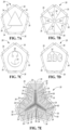
- the plurality of overlapping strips 15 may be arranged prior to assembly on the bladder 16, to define a nexus void 27.
- the nexus void 27 is disposed on the central axis A, such that the nexus void 27 is aligned with the valve 17 and the valved opening 19 and the valve 17 is disposed in the nexus void 27.
- FIGS. 8 and 10 once the plurality of strips 15 is disposed on and wrapped about the bladder 16, a uniform number of radially-stacked layers of overlapping strips 15 within the restriction structure 22 are disposed over a substantial entirety of the exterior bladder surface 21.
- the restriction structure 22 may comprise a first layer 22a of overlapping strips 15 and a second layer 22b of overlapping strips 15 over the entirety of the exterior bladder surface 21.
- Each strip 15 has a first end 44, a second end 46, a first edge 48, and a second edge 50.
- the first end 44 is positioned opposite the second end 46, such that a length 76 of the respective strip 15 is measured from the first end 44 to the second end 46.
- the first edge 48 is further positioned opposite the second edge 50, such that a width 74 of the respective strip 15 is measured from the first edge 48 to the second edge 50.
- each of the first edge 48 and the second edge 50 extend from the first end 44 to the second end 46 of each respective strip 15.
- Each strip 15 may further define an aspect ratio of length 76 to width 74.
- the aspect ratio of length 76 to width 74 may be from about 1:1 to about 15:1.
- the aspect ratio of length 76 to width 74 of the respective strip 15 may be from about 1:1 to about 5:1.
- the plurality of strips 15 may comprise a plurality of overlapping patches disposed about the entirety of the exterior bladder surface 21.
- the first layer 22a is welded to the second layer 22b across the entirety of the exterior bladder surface 21 and throughout the restriction structure 22.
- the term “welding” or variants thereof is defined as a technique for securing two elements to one another that involves a softening or melting of a polymer material within at least one of the elements such that the materials of the elements are secured to each other when cooled.
- welding or variants thereof (e.g., “thermal bond”) is defined as the bond, link, or structure that joins two elements through a process that involves a softening or melting of a polymer material within at least one of the elements such that the materials of the elements are secured to each other when cooled.
- the aspect ratio of length 76 to width 74 of the respective strip 15 may be greater than about 8:1 and more particularly about 10:1.
- the width 74 of the respective strip 15 may be quantified as from about 1/8 th to about 1/10 th of the length 76 or from about 10% to about 13% of the length 76 of the respective strip 15.
- Such length 76 and width 74 dimensions for the strips 15, namely, an aspect ratio of length 76 to width 74 of from about 8:1 to about 10:1 provide for a mitigation of waste material in the manufacture of the restriction structure 22.
- the length 76 of the respective strip 15 may be substantially the same as the measurement of the bladder circumference 30, when the sports ball 10 is inflated to the predetermined internal pressure.
- the width 74 of the respective strip 15 may be quantified as from about 1/8 th to about 1/10 th of the measurement of the bladder circumference 30, when the sports ball 10 is inflated to the predetermined internal pressure and/or from about 10% to about 13% of the bladder circumference 30, when the sports ball 10 is fully inflated to the predetermined internal pressure.
- the plurality of overlapping strips 15 is further defined as a plurality of overlapping and interwoven strips 15 ( FIG. 5 ).
- the restriction structure 22 again comprises a uniform number of radially-stacked layers of the overlapping and interwoven strips 15 over a substantial entirety of the exterior bladder surface 21, for example, two layers, namely, a first layer 22a and a second layer 22b.
- the first layer 22a is interwoven with and welded to the second layer 22b.
- each strip 15 may be formed in a linear configuration, such that each of the first edge 48 and the second edge 50 are linear. While being linear in configuration, the first edge 48 and the second edge 50 remain substantially parallel along the length 76 of the respective strip 15.
- each strip 15 may be formed in a wave-like configuration as illustrated by example in FIG. 5 .
- the first edge 48 and second edge 50 define a wave-like configuration comprising a plurality of crests and a plurality of depressions.
- the first edge 48 is non-linear and the second edge 50 is non-linear.
- the first edge 48 may define a first plurality of crests 52, a first plurality of depressions 54, and a first edge equilibrium 40.
- Each crest 52 of the first plurality of crests extends to a crest terminus 59 that is spaced apart from the first edge equilibrium 40 in a first direction D1 by a first edge crest height 70a.
- Each depression 54 of the first plurality of depressions extends to a depression terminus 71 that is spaced apart from the first edge equilibrium 40 in a second direction D2, which is opposite the first direction D1, by a first edge depression depth 72a.
- the second edge 50 may define a second plurality of crests 55, a second plurality of depressions 57, and a second edge equilibrium 42.
- Each crest 55 of the second plurality of crests extends to a crest terminus 45 that is spaced apart from the second edge equilibrium 42 in the first direction D1 by a second edge crest height 70b.
- Each depression 57 of the second plurality of depressions extends to a depression terminus 47 that is spaced apart from the second edge equilibrium 42 in the second direction D2 by a second edge depression depth 72b.
- first plurality of crests 52 and the first plurality of depressions 54 may further comprise an alternating and repeating series of crests 52 and depressions 54, such that the first edge 48 takes on a wave-like configuration.
- each crest 52 is positioned between two depressions 54 and each depression 54 is positioned between two crests 52.
- the second plurality of crests 55 and the second plurality of depressions 57 may further comprise an alternating and repeating series of crests 55 and depressions 57, such that the second edge 50 takes on a wave-like configuration.
- each crest 55 is positioned between two depressions 57 and each depression 57 is positioned between two crests 55.
- each crest 52 of the first plurality of crests is aligned with one of the crests 55 of the second plurality of crests and each depression 54 of the first plurality of depressions is aligned with one of the depressions 57 from the second plurality of depressions.
- first edge crest height 70a is substantially the same as the first edge depression depth 72a.
- the second edge crest height 70b is substantially the same as the second edge depression depth 72b.
- the first edge crest height 70a is substantially the same as the second edge crest height 70b.
- the first edge depression depth 72a is substantially the same as the second edge depression depth 72b.
- the first edge crest height 70a and the first edge depression depth 72a cooperate to define the wave amplitude of the first edge 48.
- the second edge crest height 70b and the second edge depression depth 72b cooperate to define the wave amplitude of the second edge 50.
- the wave amplitude of the first edge 48 is from about 1/8 th or 12.5% of the width 74 of the respective strip 15 to about 1/3 rd or 33% of the width 74 of the respective strip 15.
- the wave amplitude of the second edge 50 is from about 1/8 th or 12.5% of the width 74 of the respective strip 15 to about 1/3 rd or 33% of the width 74 of the respective strip 15. More particularly, in one example, the wave amplitude of each of the first edge 48 and the second edge 50 is about 1/4 th or about 25% of the width 74 of the respective strip 15.
- first crest height 70a, the second crest height 70b, the first depression depth 72a, and the second depression depth 72b may quantified as from about 1/16 th or 6.25% of the width 74 of the respective strip 15 to about 1/6 th or 17% of the width 74 of the respective strip 15.
- first crest height 70a, the second crest height 70b, the first depression depth 72a, and the second depression depth 72b may be quantified as approximately 1/8 th of or from about 12% to about 13% of the width 74 of the respective strip 15, such that the ratio of first crest height 70a to width 74 is about 1:8, the ratio of second crest height 70b to width 74 is about 1:8, the ratio of first depression depth 72a to width 74 is about 1:8, the ratio of second depression depth 72b to width 74 is about 1:8.
- the plurality of overlapping and interwoven strips 15 comprises six overlapping and interwoven strips 15, namely, a first strip 15a, a second strip 15b, a third strip 15c, a fourth strip 15d, a fifth strip 15e, and a sixth strip 15f ( FIG. 6 ).
- the first strip 15a, the second strip 15b, the third strip 15c, the fourth strip 15d, and the fifth strip 15e are positioned radially about the nexus void 27, such that the nexus void 27 is disposed between the first end 44 and the second end 46 of each of the respective strips 15 ( FIG. 6 ).
- Each of the first strip 15a, the second strip 15b, the third strip 15c, the fourth strip 15d, and the fifth strip 15e are interwoven with each of the other strips 15 ( FIG. 6 ) and wrapped about the bladder circumference 30 ( FIG. 4 ).
- the first end 44 of the respective strip 15 is positioned adjacent to and in contact with the second end 46 of that respective strip 15, such that the first end 44 abuts the second end 46 thereby forming a restrictor ring about the bladder circumference 30.
- the first end 44 of the first strip 15a is positioned adjacent to and in contact with the second end 46 of the first strip 15a
- the first end 44 of the second strip 15b is positioned adjacent to and in contact with the second end 46 of the second strip 15b
- the first end 44 of the third strip 15c is positioned adjacent to and in contact with the second end 46 of the third strip 15c
- the first end 44 of the fourth strip 15d is positioned adjacent to and in contact with the second end 46 of the fourth strip 15d
- the first end 44 of the fifth strip 15e is positioned adjacent to and in contact with the second end 46 of the fifth strip 15e, when the plurality of strips 15 of FIGS. 5 are overlapped and interwoven about the bladder circumference 30.
- the sixth strip 15f is then disposed about the equator of the bladder 16 and wrapped about the bladder circumference 30, such that the first end 44 of the sixth strip 15f is positioned adjacent to and in contact with the second end 46 of the sixth strip 15f.
- the first end 44 and second end 46 of the respective strips 15 may be fixed to one another via welding, adhesive binder, stitching, or another suitable coupling mechanism, such that the respective restrictor ring is interwoven with each of the other restrictor rings and secured about the bladder circumference 30.
- the outer cover layer 24 may be composed of a variety of suitable materials including leather and/or suitable polymeric materials.
- the outer cover layer 24 is composed of a polymeric material, a polymer foam material, or the like.
- suitable polymeric materials include, but are not limited to, polyurethane, polyvinylchloride, polyamide, polyester, polypropylene, polyolefin, and/or other materials that are generally durable and wear-resistant.
- the outer cover layer 24 may be formed of a thermoplastic polyurethane material (TPU).
- the outer cover layer 24 may be generally formed by a plurality of adjoining panels 28, wherein each panel 28 has a respective panel surface that defines a portion of the outer cover layer surface 18.
- the plurality of panels 28 may comprise the conventional twelve (12) panels or any other number of panels 28, for example, four joined panels 28 each having nine edges 36 and having a generally triangular shape that is formed from three pentagons.
- Panels 28 may also have a variety of other shapes (e.g., triangular, square, rectangular, trapezoidal, round, oval) that combine in a tessellation-type manner to form the outer cover layer 24. Further, panels 28 may also exhibit non-regular or non-geometrical shapes.
- the outer cover layer 24 may also exhibit a substantially uniform or unbroken configuration that does not include panels 28 joined at abutting edge areas 36 via seams 38 or may include fewer panels 28.
- the outer cover layer 24 may further define a plurality of surface features 34, 38, 58.
- the plurality of surface features 34, 38, 58 may include a first plurality of indentations 38, a second plurality of indentations 34, and a plurality of protrusions 58.
- the outer cover layer surface 18 may define a plurality of land areas 60 disposed between the respective indentations 34, 38 and/or protrusions 58. Further, the protrusions 58, the land areas 60, the first plurality of indentations 38, and second plurality of indentations 34 may cooperate to define a topographical arrangement across the exterior surface 13 of the sports ball 10.
- the first plurality of indentations 38 may have a first indentation terminus 63 radially-spaced apart from the outer cover layer surface 18 in a direction toward the interior bladder 16. Further, each of the first plurality of indentations 38 has a first indentation depth 41 and a first indentation width 43. The first indentation terminus 63 is radially-spaced apart from the outer cover layer surface 18 by the first indentation depth 41.
- the first plurality of indentations 38 may be defined as a plurality of seams 38 configured to couple the plurality of panels 28. In one example, the first plurality of indentations 38 are defined as seams, the first indentation width 43 is a seam width and the first indentation depth 41 is a seam depth.
- the respective panels 28 may be joined together along abutting edge areas 36 ( FIG. 7A-7E ) via at least one seam 38 ( FIGS. 1 and 3 ).
- the panels 28 may be coupled along the abutting edge areas 36 by the seam 38 with stitching, bonding, welding, adhesives, or another suitable coupling method.
- welded seams 38 An example of welded seams 38 is disclosed in U.S. Patent No. 8,608,599 to Raynak, et al.
- U.S. Patent No. 8,608,599 to Raynak, et al. generally discloses examples of welded seams, in that welding generally produces a heat affected zone in which the materials of the two joined components are intermingled.
- This heat affected zone may be considered a "weld” or "thermal bond.”
- welding may involve (a) the melting or softening of two panels that include polymer materials such that the polymer materials from each panel intermingle with each other (e.g., diffuse across a boundary layer between the polymer materials) and are secured together when cooled, as well as (b) the melting or softening of a polymer material in a first panel such that the polymer material extends into or infiltrates the structure of a second panel (e.g., infiltrates crevices or cavities formed in the second panel or extends around or bonds with filaments or fibers in the second panel) to secure the panels together when cooled.
- welding may occur when only one panel includes a polymer material or when both panels include polymer materials.
- each of the second plurality of indentations 34 may have a second indentation terminus 65 radially-spaced apart from the outer cover layer surface 18 in a direction toward the interior bladder 16. Further, each of the second plurality of indentations 34 has a second indentation depth 67 and a second indentation width 61. The second indentation terminus 65 is radially-spaced apart from the outer cover layer surface 18 by the second indentation depth 67.
- the second plurality of indentations 34 may be defined as a plurality of channels.
- the channels 34 may be spaced apart from the seams 38 of the sports ball 10 ( FIGS. 7A, 7C, 7D, 7E ).
- the channels 34 may extend to edges 36 of the panels 28 and, thus, continue across a respective seam 38 ( FIG 7B ). More particularly, a channel 34 on a first panel and a channel 34 on a second panel may be in substantial alignment with one another across a respective seam 38. This may also enable patterns, arrangements, or other designs to be carried across multiple panels, bridging seams 38 between the panels 28.
- Channels 34 may impart various advantages to ball 10. For example, channels 34 may enhance the aerodynamics of ball 10, provide a greater amount of consistency or control over ball 10 during play, e.g., during kicking, dribbling, or passing, improve ball feel, and provide for water channeling.
- Channels 34 may be formed in the outer cover layer 24 via a variety of manufacturing processes including, but not limited to, debossing. Examples of a manufacturing process for forming channels 34 are disclosed in U.S. Patent No. 9,370,693 to Berggren, et al. U.S. Patent No. 9,370,693 to Berggren, et al. generally discloses a variety of manufacturing processes that may be utilized to form debossed features in panels. In one example, one of the panels is located on a platen. A press plate is positioned above the platen and includes an extension portion having a predetermined shape. The extension portion presses into and heats the areas of panel forming the debossed features. The press plate then moves away from the panel to substantially complete the formation of the debossed feature.
- each channel 34 has a channel terminus 65 that is radially-spaced apart from the outer cover layer surface 18 in a direction toward the interior bladder 16. Further, each channel 34 has a channel depth 67 and a channel width 61. The channel terminus 65 is radially-spaced apart from the outer cover layer surface 18 the channel depth 67.
- the channels 34 are formed in the outer cover layer 24 and extend toward the interior bladder 16.
- the intermediate layers 26a, 26b of the intermediate structure 14 are positioned between outer cover layer 24 and the restriction structure 22.
- the outer cover layer 24 may be bonded to one of the intermediate layers 26a, 26b at the respective channel 34. More particularly, the outer cover layer 24 may be welded directly to the second intermediate layer 26b at the channel terminus 65 of the respective channel 34 ( FIGS. 11A-C and 11E-G ), such that the outer cover layer 24 extends through an entirety of the channel depth 67 at each of the channels 34.
- the channel 34 may include an exterior indentation 82 and an interior indentation 84.
- the exterior indentation 82 has the terminus 65 that is radially-spaced apart from the outer cover layer surface 18 by the channel depth 67.
- the exterior and interior indentations 82 and 84 may have a generally rounded configuration. As depicted in FIG. 11A the interior and exterior indentations 82 and 84 extend to an approximate midpoint of a thickness 88 of the panel cross-section. In another configuration, as depicted in FIG. 11B , the exterior indentation 82 extends through more of the thickness 88 of panel cross section than the interior indentation 84. In yet another configuration, as depicted in FIG. 11C , the exterior indentation 82 extends through substantially all of the thickness 88 of panel cross-section. As also shown in FIG.
- the second intermediate layer 26b may have a substantially planar configuration opposite the exterior indentation 82.
- the channel 34 may have only an exterior indentation 82 and no interior indentation 84.
- indentations 82 and 84, as well as the outer cover layer 24 and the second intermediate layer 26b, may be spaced from each other, such that a portion of the first intermediate layer 26a extends between indentations 82 and 84 and between the outer cover layer 24 and the second intermediate layer 26b.
- the outer cover layer 24 is bonded to the first intermediate layer 26a at the channel 34.
- the first intermediate layer 26a has a first thickness 90 between indentations 82 and 84 and at the terminus 65 of the exterior indentation 82.
- the first intermediate layer 26a has a second thickness 92 between the outer cover layer 24 and the second intermediate layer 26b, in an area spaced apart from indentations 82 and 84 and the terminus 65 of the exterior indentation 82. As shown in FIG. 11D , the first thickness 90 is less than the second thickness 92.
- the channels 34 may include an exterior indentation 82 and an interior indentation 84 that exhibit substantially squared configurations ( FIGS. 11E-11G ).
- the indentations 82, 84 may have substantially squared cross-sectional configurations. Such substantially squared cross-sectional configurations may have a more distinct appearance than indentations 82, 84 having substantially rounded cross-sectional configurations.
- substantially squared indentations 82, 84 may also provide performance benefits such as aerodynamics, ball feel, and water channeling.
- the exterior indentation 82 and interior indentation 84 are two opposing indentations having substantially squared cross-sectional configurations.
- the indentations 82 and 84 extend to an approximate midpoint of the thickness 88 of the panel cross-section, such that the terminus 65 of the exterior indentation 82 is positioned radially inward from the outer cover layer surface 18 to the approximate midpoint of the thickness 88 of the panel cross-section.
- the exterior indentation 82 may extend through substantially the entirety of the thickness 88 of the panel cross section.
- second intermediate layer 26b may have a substantially planar configuration opposite the exterior indentation 82.
- the channel 34 may have only an exterior indentation 82 with no interior indentation 84.
- the channel 34 may include substantially-squared exterior indentation 82 having a rounded shoulder portion 81.
- a substantially-squared shoulder portion 81 may have a minimal radius, as shown in FIG. 11F .
- a rounded shoulder portion 81 having a larger radius may be used, as shown in FIG. 11G .
- the plurality of surface features may further include a plurality of protrusions 58.
- the plurality of protrusions 58 may be disposed upon the outer cover layer surface 18.
- the protrusions 58 may form decorative or aesthetic arrangements or designs upon the outer cover layer surface 18 of the sports ball 10, display branding of the sports ball 10, via a logo contained therein, and may further be applied in such an orientation as to optimize grip at the point of contact with the user's hand and/or foot, or to improve aerodynamics during flight.
- the protrusions 58 may be disposed on a small portion of the outer cover layer surface 18, on a single panel surface, on a select group of panel surfaces, or upon a majority of the outer cover layer surface 18 ( FIG. 7E ).
- Each of the protrusions 58 may be formed of a dimensional ink and extend from the outer cover layer surface 18. As shown in FIG. 10 , each of the plurality of the protrusions 58 has a terminus 62 that is radially spaced apart from the outer cover layer surface 18 by a height 64 that is greater than about 0.05 millimeters (mm). In such examples, it is beneficial for the height 64 to be at least 0.05 millimeters (mm) and less than 0.15 millimeters (mm) in order to enhance playability of the ball 10.
- protrusions 58 having heights 64 in the aforementioned range allow for visibility of the respective panel designs and an overall topographical arrangement of the sports ball 10, while also exhibiting a desired grip or contact between a user and/or player's hand or foot and the exterior surface 13 of the ball 10, all while still allowing the ball 10 to maintain desired aerodynamic and flight characteristics.
- the casing 12 may further include an external surface layer 25 disposed upon the outer cover layer surface 18.
- the external surface layer 25 may be a film that includes a pigment or a graphic thereon.
- the external surface layer 25 may also be an outer film or clear coat having weather resistant properties.
- the external surface layer 25 may be a polyurethane film or the like.
- the external surface layer 25 may be bonded to the outer cover layer surface 18 via a bonding material.
Landscapes
- Health & Medical Sciences (AREA)
- General Health & Medical Sciences (AREA)
- Physical Education & Sports Medicine (AREA)
- Professional, Industrial, Or Sporting Protective Garments (AREA)
Claims (15)
- Ein aufblasbarer Sportball (10), der Folgendes umfasst:eine Blase (16), die auf einen vorbestimmten Innendruck aufblasbar ist, wobei die Blase (16) eine äußere Blasenoberfläche (21) definiert;eine Hülle (12), die um die Blase (16) herum angeordnet ist, wobei die Hülle (12) Folgendes umfasst:eine äußere Deckschicht (24);eine Zwischenstruktur (14), die zwischen der Blase (16) und der äußeren Deckschicht (24) angeordnet ist, wobei die Zwischenstruktur (14) eine Restriktionsstruktur (22) umfasst, wobei die Restriktionsstruktur (22) eine Vielzahl von überlappenden Streifen (15) umfasst;wobei die Restriktionsstruktur (22) eine gleichmäßige Anzahl von radial gestapelten Schichten der überlappenden Streifen (15) im Wesentlichen über einer Gesamtheit der äußeren Blasenoberfläche (21) umfasst;wobei die Blase (16) eine Ventilöffnung definiert, die konfiguriert ist, um ein Ventil (17) aufzunehmen, wobei das Ventil (17) konfiguriert ist, um ein selektives Aufblasen der Blase (16) auf den vorbestimmten Innendruck zu ermöglichen, sodass die Blase (16) einen Blasenumfang (30) definiert, wenn die Blase (16) auf den vorbestimmten Innendruck aufgeblasen ist; unddadurch gekennzeichnet, dassdie Vielzahl von überlappenden Streifen (15) eine Vielzahl von miteinander verflochtenen (interwoven) Streifen (15) ist, wobei jeder Streifen (15) mit jedem der anderen Streifen (15) verflochten ist und um den Blasenumfang (30) gewickelt ist.
- Der aufblasbare Sportball (10) nach Anspruch 1, wobei die Vielzahl von überlappenden Streifen (15) eine Verbindungslücke bzw. einen Verbindungsfreiraum (nexus void) (27) definiert; und wobei der Verbindungsfreiraum (27) mit der Ventilöffnung ausgerichtet ist, sodass das Ventil (17) im Verbindungsfreiraum (27) enthalten ist.
- Der aufblasbare Sportball (10) nach Anspruch 2, wobei der aufblasbare Sportball (10) ein inneres Zentrum (31) aufweist, das auf einer Mittelachse (A) angeordnet ist, und wobei jeder von dem Verbindungsfreiraum (27), der Ventilöffnung und dem Ventil (17) auf der Mittelachse (A) positioniert sind, wobei der aufblasbare Sportball (10) ferner Folgendes umfasst:ein Gegengewicht (32), das auf der Mittelachse (A) diametral gegenüber dem Ventil (17), der Ventilöffnung und dem Verbindungsfreiraum (27) angeordnet ist, wenn die Blase (16) auf den vorbestimmten Innendruck aufgeblasen ist; undwobei das Gegengewicht (32) zumindest eines von einem Schaumstoff-Patch oder einem Textil-Patch beinhaltet.
- Der aufblasbare Sportball (10) nach irgendeinem der Ansprüche von 1 bis 2, wobei die Zwischenstruktur (14) ferner Folgendes umfasst:eine erste Zwischenschicht (26a);eine zweite Zwischenschicht (26b), die zwischen der ersten Zwischenschicht (26a) und der Restriktionsstruktur (22) angeordnet ist, wobei die erste Zwischenschicht (26a) zwischen der zweiten Zwischenschicht (26b) und der äußeren Deckschicht (24) angeordnet ist; undwobei mindestens eine von der ersten Zwischenschicht (26a) oder der zweiten Zwischenschicht (26b) ein thermoplastisches Polyurethan-Schaumstoffmaterial umfasst.
- Der aufblasbare Sportball (10) nach irgendeinem der Ansprüche von 1 bis 4, wobei:
die äußere Deckschicht (24) ferner Folgendes umfasst:eine Vielzahl von angrenzenden Platten (28), die an einer Vielzahl von Nähten gekoppelt sind, wobei jede Naht eine Nahtbreite und eine Nahttiefe aufweist;eine Vielzahl von Kanälen, die durch die äußere Deckschicht (24) definiert sind und von jeder der Nähte beabstandet sind, wobei jeder Kanal eine Kanalbreite und eine Kanaltiefe aufweist, wobei die äußere Deckschicht (24) an jedem Kanal direkt mit der zweiten Zwischenschicht (26b) verklebt bzw. verbunden ist (bonded); undeine Vielzahl von Vorsprüngen, die sich von der Oberfläche der äußeren Deckschicht (18) zu einem Vorsprungende erstrecken, wobei das Vorsprungende von der Oberfläche der äußeren Deckschicht (18) radial um eine Vorsprunghöhe beabstandet ist, die größer als etwa 0,05 Millimeter ist. - Der aufblasbare Sportball (10) nach den Ansprüchen von 1 bis 5, wobei jeder der überlappenden Streifen (15) ein Elastomermaterial umfasst, sodass die Vielzahl überlappender Streifen (15) eine Vielzahl überlappender Elastomerstreifen (15) ist, wobei die erste Zwischenschicht (26a) ein thermoplastisches Polyurethan-Schaumstoffmaterial umfasst, und wobei die zweite Zwischenschicht (26b) eine Wickelschicht umfasst, die ein Textilfilament umfasst, das wiederholt um im Wesentlichen eine Gesamtheit der Restriktionsstruktur (22) gewickelt ist und diese bedeckt; oder
wobei jeder der überlappenden Streifen (15) ein Textilmaterial umfasst, sodass die Vielzahl der überlappenden Streifen (15) eine Vielzahl von überlappenden Textilstreifen (15) ist, und optional wobei das Textilmaterial mit einem thermoplastischen Material imprägniert ist. - Der aufblasbare Sportball (10) nach den Ansprüchen von 1 bis 6, wobei jeder der überlappenden Streifen (15) ferner Folgendes umfasst:ein erstes Ende (44) und ein zweites Ende (46) gegenüber dem ersten Ende (44);eine Länge (76), gemessen vom ersten Ende (44) zum zweiten Ende (46);eine erste Kante (48) und eine zweite Kante (50), die gegenüber der ersten Kante (48) angeordnet ist, wobei sich jede von der ersten Kante (48) und der zweiten Kante (50) vom ersten Ende (44) zum zweiten Ende (46) erstrecken;eine Breite (74), die von der ersten Kante (48) zur zweiten Kante (50) gemessen wird; undwobei die erste Kante (48) im Wesentlichen parallel zur zweiten Kante (50) ist.
- Der aufblasbare Sportball (10) nach Anspruch 7, wobei jeder Streifen (15) ein Seitenverhältnis der Länge (76) zur Breite (74) von etwa 1:1 bis etwa 15:1 definiert, und optional
wobei jeder Streifen (15) ein Seitenverhältnis der Länge (76) zur Breite (74) von mehr als 8:1 definiert. - Der aufblasbare Sportball (10) nach irgendeinem der Ansprüche von 7 bis 8, wobei:die Länge (76) jedes Streifens (15) gleich dem Blasenumfang (30) ist; und wobeidas erste Ende (44) jedes einzelnen Streifens (15) am zweiten Ende (46) des jeweiligen Streifens (15) befestigt ist, sodass jeder der überlappenden Streifen (15) einen Restriktionsring um den Blasenumfang (30) bildet, wenn die Blase (16) auf den vorbestimmten Innendruck aufgeblasen wird, sodass die Restriktionsstruktur (22) geformt ist, um mit der äußeren Blasenoberfläche (21) übereinzustimmen.
- Der aufblasbare Sportball (10) nach irgendeinem der Ansprüche von 7 bis 9, wobei die erste Kante (48) nicht linear ist und die zweite Kante (50) nicht linear ist.
- Der aufblasbare Sportball (10) nach Anspruch 10, wobeidie erste Kante (48) eine erste Vielzahl von Kuppen bzw. Kämmen (crests) (52), eine erste Vielzahl von Vertiefungen (54) und ein erstes KantenGleichgewicht (40) definiert;jeder Kamm (52) der ersten Vielzahl von Kämmen (52) sich zu einem Kammendpunkt (59) hin erstreckt, der von dem ersten Kantengleichgewicht (40) in einer ersten Richtung (D1) um eine erste Kammhöhe (70a) beabstandet ist; und wobeijede Vertiefung (54) der ersten Vielzahl von Vertiefungen (54) sich zu einem Vertiefungsendpunkt (71) hin erstreckt, der von dem ersten Kantengleichgewicht (40) in einer zweiten Richtung (D2) um eine erste Kantenvertiefungstiefe (72a) beabstandet ist; und wobeidie erste Richtung (D1) entgegengesetzt zur zweiten Richtung (D2) ist.
- Der aufblasbare Sportball (10) nach Anspruch 11, wobei:die zweite Kante (50) eine zweite Vielzahl von Kämmen (55), eine zweite Vielzahl von Vertiefungen (57) und ein zweites Kantengleichgewicht (42) definiert;jeder Kamm (55) der zweiten Vielzahl von Kämmen (55) sich zu einem Kammendpunkt (45) hin erstreckt, der von dem zweiten Kantengleichgewicht (42) in der ersten Richtung (D1) um eine zweite Kammhöhe (70b) beabstandet ist; und wobeijede Vertiefung (57) der zweiten Vielzahl von Vertiefungen (57) sich zu einem Vertiefungsendpunkt (47) hin erstreckt, der von dem zweiten Kantengleichgewicht (42) in der zweiten Richtung (D2) um eine zweite Kantenvertiefungstiefe (72b) beabstandet ist.
- Der aufblasbare Sportball (10) nach Anspruch 12, wobei:die erste Vielzahl von Kämmen (52) und die erste Vielzahl von Vertiefungen (54) eine alternierende und sich wiederholende Reihe von Kämmen (52) und Vertiefungen (54) umfassen, sodass jeder Kamm (52) zwischen zwei Vertiefungen (54) und jede Vertiefung (54) zwischen zwei Kämmen (52) positioniert ist;die zweite Vielzahl von Kämmen (55) und die zweite Vielzahl von Vertiefungen (57) eine alternierende und sich wiederholende Reihe von Kämmen (55) und Vertiefungen (57) umfassen, sodass jeder Kamm (55) zwischen zwei Vertiefungen (57) und jede Vertiefung (57) zwischen zwei Kämmen (55) positioniert ist; und wobeijeder Kamm (52) der ersten Vielzahl von Kämmen (52) mit einem der Kämme (55) der zweiten Vielzahl von Kämmen (55) ausgerichtet ist und jede Vertiefung (54) der ersten Vielzahl von Vertiefungen (54) mit einer der Vertiefungen (57) der zweiten Vielzahl von Vertiefungen (57) ausgerichtet ist.
- Der aufblasbare Sportball (10) nach irgendeinem der Ansprüche von 12 bis 13, wobeidie Kammhöhe (70a) der ersten Kante gleich der Vertiefungstiefe (72a) der ersten Kante ist;die Kammhöhe (70b) der zweiten Kante gleich der Vertiefungstiefe (72b) der zweiten Kante ist;die Kammhöhe (70a) der ersten Kante gleich der Kammhöhe (70b) der zweiten Kante ist; und wobeidie Vertiefungstiefe (72a) der ersten Kante gleich der Vertiefungstiefe (72b) der zweiten Kante ist.
- Der aufblasbare Sportball (10) nach Anspruch 14, wobei:das Seitenverhältnis der Länge (76) zur Breite (74) jedes der jeweiligen Streifen (15) etwa 10:1 beträgt;ein Verhältnis der Kammhöhe (70a) der ersten Kante zur Breite (74) des jeweiligen Streifens (15) etwa 1:8 beträgt;ein Verhältnis der Kammhöhe (70b) der zweiten Kante zur Breite (74) des jeweiligen Streifens (15) etwa 1:8 beträgt;ein Verhältnis der Vertiefungstiefe (72a) der ersten Kante zur Breite (74) des jeweiligen Streifens (15) etwa 1:8 beträgt; und wobeiein Verhältnis der Vertiefungstiefe (72b) der zweiten Kante zur Breite (74) des jeweiligen Streifens (15) etwa 1:8 beträgt, und, optional,wobei die Vielzahl der verflochtenen Streifen (15) sechs Streifen (15) umfasst, bestehend aus einem ersten Streifen (15a), einem zweiten Streifen (15b), einem dritten Streifen (15c), einem vierten Streifen (15d), einem fünften Streifen (15e) und einem sechsten Streifen (15f), und wobei die gleichmäßige Anzahl von radial gestapelten Schichten zwei Schichten umfasst, bestehend aus einer ersten Schicht (22a) und einer zweiten Schicht (22b).
Applications Claiming Priority (2)
| Application Number | Priority Date | Filing Date | Title |
|---|---|---|---|
| US202063030279P | 2020-05-26 | 2020-05-26 | |
| PCT/US2021/025389 WO2021242406A1 (en) | 2020-05-26 | 2021-04-01 | Inflatable sports ball with restriction structure |
Publications (2)
| Publication Number | Publication Date |
|---|---|
| EP4157472A1 EP4157472A1 (de) | 2023-04-05 |
| EP4157472B1 true EP4157472B1 (de) | 2025-04-30 |
Family
ID=75660354
Family Applications (1)
| Application Number | Title | Priority Date | Filing Date |
|---|---|---|---|
| EP21721299.2A Active EP4157472B1 (de) | 2020-05-26 | 2021-04-01 | Aufblasbarer sportball mit beschränkungsstruktur |
Country Status (3)
| Country | Link |
|---|---|
| US (1) | US11833397B2 (de) |
| EP (1) | EP4157472B1 (de) |
| WO (1) | WO2021242406A1 (de) |
Families Citing this family (2)
| Publication number | Priority date | Publication date | Assignee | Title |
|---|---|---|---|---|
| WO2020230428A1 (ja) * | 2019-05-10 | 2020-11-19 | 株式会社モルテン | 組立式ボール |
| DE102024118151A1 (de) | 2024-06-27 | 2025-12-31 | Adidas Ag | Ball mit einem facettierten Oberflächendesign und einem Verfahren zum Herstellen eines facettierten Oberflächendesigns. |
Family Cites Families (78)
| Publication number | Priority date | Publication date | Assignee | Title |
|---|---|---|---|---|
| GB301302A (en) * | 1928-10-01 | 1929-12-05 | Zoltan Fay | Improvements in or relating to football or like cases |
| US2221533A (en) | 1937-11-06 | 1940-11-12 | William J Voit | Athletic ball |
| US2380370A (en) * | 1945-04-02 | 1945-07-10 | Sun Rubber Co | Inflatable athletic ball and method of making same |
| US2623747A (en) * | 1947-01-24 | 1952-12-30 | Seamless Rubber Co | Inflatable athletic ball and method of making |
| US2627892A (en) * | 1947-03-13 | 1953-02-10 | Sun Rubber Co | Method of making play balls |
| US2653818A (en) | 1949-01-22 | 1953-09-29 | Voit Rubber Corp | Fabric reinforced football |
| US2688488A (en) * | 1949-09-09 | 1954-09-07 | Seamless Rubber Co | Inflated athletic ball and method of making |
| US2945693A (en) * | 1957-06-03 | 1960-07-19 | Voit Rubber Corp | Reinforced ball |
| US3506265A (en) | 1967-04-19 | 1970-04-14 | Molten Rubber Ind | Multiple-ply,inflated ball for games |
| JPS5829112B2 (ja) | 1978-02-02 | 1983-06-20 | タチカラ株式会社 | ボ−ルの製造方法 |
| US4415154A (en) * | 1981-02-25 | 1983-11-15 | Engelhardt Gerald J | Ball and target |
| US4462590A (en) * | 1982-10-22 | 1984-07-31 | Figgie International Inc. | Inflatable padded game ball |
| US4542902A (en) * | 1984-03-15 | 1985-09-24 | Ideas That Sell, Inc. | Soccer ball and method of making same |
| US4570931A (en) | 1984-04-03 | 1986-02-18 | Wilson Sporting Goods Co. | Basketball |
| US4660831A (en) * | 1985-09-16 | 1987-04-28 | Figgie International Inc. | Inflatable padded game ball |
| US4856781A (en) | 1986-01-16 | 1989-08-15 | Molten Corporation | Game ball |
| US5096756A (en) * | 1990-04-02 | 1992-03-17 | Wilson Sporting Goods Co. | Composite bladder for game balls |
| US5294112A (en) * | 1993-04-26 | 1994-03-15 | Smith Eldon F | Bladder for use in a sportsball |
| USRE37468E1 (en) | 1994-10-13 | 2001-12-11 | Spalding Sports Worldwide, Inc. | Game ball with synthetic leather cover |
| US6013340A (en) | 1995-06-07 | 2000-01-11 | Nike, Inc. | Membranes of polyurethane based materials including polyester polyols |
| US20020086749A1 (en) | 2001-01-02 | 2002-07-04 | Ou Tsung Ming | Sportsball and manufacturing method thereof |
| JPH10265588A (ja) | 1997-01-24 | 1998-10-06 | Mitsui Chem Inc | オレフィン系共重合体製収縮フィルム |
| US6039662A (en) | 1998-04-21 | 2000-03-21 | Joyful Long International Ltd. | Inflatable stitched sports ball and method of making same |
| TW407060B (en) | 1998-05-22 | 2000-10-01 | Molten Corp | Ball for ball game |
| JP2003531700A (ja) | 2000-05-01 | 2003-10-28 | 株式会社モルテン | 球技用ボールおよびその製法 |
| US6348018B1 (en) | 2000-05-25 | 2002-02-19 | Top Ball Trading Co., Ltd | American football supported with air layer |
| US6663520B2 (en) | 2001-10-15 | 2003-12-16 | Li Chin Ou Chen | Stitching ball with intermediate construction ball pocket |
| US6638189B2 (en) * | 2001-12-28 | 2003-10-28 | Mei Huei Liu | Inflatable game ball and method of making same |
| US20030228946A1 (en) | 2002-06-11 | 2003-12-11 | Chan Chong Veng | Sports balls |
| DE10255092B4 (de) | 2002-11-26 | 2010-11-11 | Molten Corp. | Verfahren zur Herstellung von Teilstücken eines Balls |
| CN100374174C (zh) * | 2002-12-20 | 2008-03-12 | 株式会社宝登 | 球类运动用球及其制造方法 |
| US7699726B2 (en) | 2003-04-23 | 2010-04-20 | Nike, Inc. | Game ball incorporating a polymer foam |
| CN1323731C (zh) * | 2004-06-09 | 2007-07-04 | 唐雅芳 | 竞技用球的内胆及该竞技用球 |
| US20080051233A1 (en) | 2004-09-07 | 2008-02-28 | Callaway Golf Company | Game balls with cover containing post crosslinkable thermoplastic polyurethane and method of making same |
| EP1709998B1 (de) | 2005-04-08 | 2011-07-13 | Goedoen Holding FZC | Sportball mit Gewebe, und Verfahren zu seiner Herstellung |
| WO2007033435A1 (en) | 2005-09-26 | 2007-03-29 | Heritage Sporting Products Pty Ltd | A ball |
| US20080044635A1 (en) | 2006-06-08 | 2008-02-21 | O'neill Michael | Barrier film for flexible articles |
| US7585236B2 (en) | 2006-08-02 | 2009-09-08 | Wilson Sporting Goods Co. | Game ball having optimally positioned grooves and/or ridges |
| US8251846B2 (en) | 2006-08-02 | 2012-08-28 | Wilson Sporting Goods Co. | Game ball having optimally positioned grooves |
| US7862458B2 (en) | 2006-09-20 | 2011-01-04 | Nike, Inc. | Panel configuration for a game ball |
| US8388476B2 (en) | 2006-12-11 | 2013-03-05 | Tsung Ming Ou | Sports ball |
| US7837581B2 (en) | 2006-12-11 | 2010-11-23 | Tsing Ming Ou | Sports ball |
| US8684870B2 (en) | 2007-04-12 | 2014-04-01 | Molten Corporation | Ball |
| US8974329B2 (en) | 2007-09-10 | 2015-03-10 | Russell Brands, Llc | Game ball |
| US8182379B2 (en) | 2008-06-27 | 2012-05-22 | Nike, Inc. | Sport balls and methods of manufacturing the sport balls |
| US8210973B2 (en) | 2008-06-27 | 2012-07-03 | Nike, Inc. | Sport ball bladder |
| US8708847B2 (en) | 2008-06-27 | 2014-04-29 | Nike, Inc. | Sport ball casing and methods of manufacturing the casing |
| US8192311B2 (en) * | 2008-06-27 | 2012-06-05 | Nike, Inc. | Sport ball with a textile restriction structure |
| US8852039B2 (en) | 2011-06-28 | 2014-10-07 | Nike, Inc. | Sport ball casing with integrated bladder material |
| CN201337790Y (zh) | 2008-12-30 | 2009-11-04 | 龙伟实业股份有限公司 | 无缝球结构改良 |
| US8974330B2 (en) | 2009-03-20 | 2015-03-10 | Nike, Inc. | Sport ball casing and methods of manufacturing the casing |
| US8608599B2 (en) | 2009-03-20 | 2013-12-17 | Nike, Inc. | Sport ball casing and methods of manufacturing the casing |
| US8579743B2 (en) | 2010-01-05 | 2013-11-12 | Nike, Inc. | Sport balls and methods of manufacturing the sport balls |
| US20140179468A1 (en) | 2010-01-05 | 2014-06-26 | Nike, Inc. | Sport Balls Having Seam Reinforcing Strips |
| US8617011B2 (en) | 2010-12-03 | 2013-12-31 | Nike, Inc. | Sport ball with indented casing |
| US9370693B2 (en) | 2010-12-03 | 2016-06-21 | Nike, Inc. | Sport ball with indented casing |
| US8672784B2 (en) | 2011-05-04 | 2014-03-18 | Nike, Inc. | Sport ball with an inflation-retention bladder |
| US8771115B2 (en) | 2011-05-04 | 2014-07-08 | Nike, Inc. | Sport ball with an inflation-retention bladder |
| US8597144B2 (en) | 2011-06-28 | 2013-12-03 | Nike, Inc. | Sport ball casing with thermoplastic reinforcing material |
| US9114286B2 (en) | 2011-09-02 | 2015-08-25 | Wilson Sporting Goods Co. | Basketball having grooved seams |
| US9017192B1 (en) | 2012-02-08 | 2015-04-28 | Roberto Silva | Athletic training device |
| US8926459B2 (en) | 2012-03-30 | 2015-01-06 | Nike, Inc. | Sport balls and methods of manufacturing the sport balls |
| WO2013148946A1 (en) | 2012-03-30 | 2013-10-03 | Nike International Ltd. | Sport ball casing and methods of manufacturing the casing |
| US9211446B2 (en) * | 2013-03-15 | 2015-12-15 | Nike, Inc. | Sport ball bladder with a pocket |
| US9089744B2 (en) | 2013-08-08 | 2015-07-28 | Chien-Chuan LO | Inflatable sports ball having a woven outer layer |
| WO2015103254A1 (en) | 2013-12-30 | 2015-07-09 | PowerHandz Inc. | Sports-training ball assembly |
| USD800854S1 (en) * | 2015-04-02 | 2017-10-24 | Matthew John O'Malley | Soccer ball |
| DE102015208524B3 (de) | 2015-05-07 | 2016-08-11 | Adidas Ag | Karkasse für einen Sportball |
| DE102015209811B3 (de) | 2015-05-28 | 2016-12-01 | Adidas Ag | Nicht-aufblasbare Sportbälle |
| CN104960213B (zh) | 2015-06-11 | 2018-06-19 | 通城辉隆体育用品有限公司 | 一种无胶贴皮球及制作工艺 |
| US20170050089A1 (en) | 2015-08-17 | 2017-02-23 | 2nd Skull, LLC | Impact dissipating ball |
| AU2015408609B2 (en) | 2015-09-11 | 2018-04-19 | Vikas Gupta | Ball for ball sports and manufacturing method for ball for ball sports |
| DE102015223885B4 (de) * | 2015-12-01 | 2024-03-21 | Adidas Ag | Ball |
| WO2018080912A1 (en) | 2016-10-24 | 2018-05-03 | Nike Innovate C.V. | Sport ball and casing defining a major channel and a minor channel |
| US10350460B2 (en) | 2017-02-28 | 2019-07-16 | Nike, Inc. | Sports ball |
| US10207158B2 (en) | 2017-02-28 | 2019-02-19 | Nike, Inc. | Sports ball |
| US10258836B2 (en) | 2017-05-25 | 2019-04-16 | Nike, Inc. | Sports ball with mechanoluminescence |
| WO2020112624A1 (en) | 2018-11-29 | 2020-06-04 | Nike Innovate C.V. | Sports ball and method of manufacture |
-
2021
- 2021-04-01 WO PCT/US2021/025389 patent/WO2021242406A1/en not_active Ceased
- 2021-04-01 US US17/220,493 patent/US11833397B2/en active Active
- 2021-04-01 EP EP21721299.2A patent/EP4157472B1/de active Active
Also Published As
| Publication number | Publication date |
|---|---|
| US20210370143A1 (en) | 2021-12-02 |
| US11833397B2 (en) | 2023-12-05 |
| EP4157472A1 (de) | 2023-04-05 |
| WO2021242406A1 (en) | 2021-12-02 |
Similar Documents
| Publication | Publication Date | Title |
|---|---|---|
| US10398944B2 (en) | Sport ball with indented casing | |
| US9254424B2 (en) | Sport ball with indented casing | |
| US11202941B2 (en) | Sport ball and casing defining a major channel and a minor channel | |
| US11167179B2 (en) | Sports ball and method of manufacture | |
| EP3843862B1 (de) | Sportball | |
| EP4157472B1 (de) | Aufblasbarer sportball mit beschränkungsstruktur | |
| EP3708228B1 (de) | Sportball mit gekerbter hülle | |
| US11759681B2 (en) | Sports ball with staggered surface features |
Legal Events
| Date | Code | Title | Description |
|---|---|---|---|
| STAA | Information on the status of an ep patent application or granted ep patent |
Free format text: STATUS: UNKNOWN |
|
| STAA | Information on the status of an ep patent application or granted ep patent |
Free format text: STATUS: THE INTERNATIONAL PUBLICATION HAS BEEN MADE |
|
| PUAI | Public reference made under article 153(3) epc to a published international application that has entered the european phase |
Free format text: ORIGINAL CODE: 0009012 |
|
| STAA | Information on the status of an ep patent application or granted ep patent |
Free format text: STATUS: REQUEST FOR EXAMINATION WAS MADE |
|
| 17P | Request for examination filed |
Effective date: 20221124 |
|
| AK | Designated contracting states |
Kind code of ref document: A1 Designated state(s): AL AT BE BG CH CY CZ DE DK EE ES FI FR GB GR HR HU IE IS IT LI LT LU LV MC MK MT NL NO PL PT RO RS SE SI SK SM TR |
|
| P01 | Opt-out of the competence of the unified patent court (upc) registered |
Effective date: 20230515 |
|
| DAV | Request for validation of the european patent (deleted) | ||
| DAX | Request for extension of the european patent (deleted) | ||
| GRAP | Despatch of communication of intention to grant a patent |
Free format text: ORIGINAL CODE: EPIDOSNIGR1 |
|
| STAA | Information on the status of an ep patent application or granted ep patent |
Free format text: STATUS: GRANT OF PATENT IS INTENDED |
|
| INTG | Intention to grant announced |
Effective date: 20241122 |
|
| GRAS | Grant fee paid |
Free format text: ORIGINAL CODE: EPIDOSNIGR3 |
|
| GRAA | (expected) grant |
Free format text: ORIGINAL CODE: 0009210 |
|
| STAA | Information on the status of an ep patent application or granted ep patent |
Free format text: STATUS: THE PATENT HAS BEEN GRANTED |
|
| AK | Designated contracting states |
Kind code of ref document: B1 Designated state(s): AL AT BE BG CH CY CZ DE DK EE ES FI FR GB GR HR HU IE IS IT LI LT LU LV MC MK MT NL NO PL PT RO RS SE SI SK SM TR |
|
| REG | Reference to a national code |
Ref country code: CH Ref legal event code: EP Ref country code: GB Ref legal event code: FG4D |
|
| REG | Reference to a national code |
Ref country code: DE Ref legal event code: R096 Ref document number: 602021029996 Country of ref document: DE |
|
| REG | Reference to a national code |
Ref country code: IE Ref legal event code: FG4D |
|
| REG | Reference to a national code |
Ref country code: NL Ref legal event code: MP Effective date: 20250430 |
|
| REG | Reference to a national code |
Ref country code: AT Ref legal event code: MK05 Ref document number: 1789523 Country of ref document: AT Kind code of ref document: T Effective date: 20250430 |
|
| PG25 | Lapsed in a contracting state [announced via postgrant information from national office to epo] |
Ref country code: FI Free format text: LAPSE BECAUSE OF FAILURE TO SUBMIT A TRANSLATION OF THE DESCRIPTION OR TO PAY THE FEE WITHIN THE PRESCRIBED TIME-LIMIT Effective date: 20250430 Ref country code: PT Free format text: LAPSE BECAUSE OF FAILURE TO SUBMIT A TRANSLATION OF THE DESCRIPTION OR TO PAY THE FEE WITHIN THE PRESCRIBED TIME-LIMIT Effective date: 20250901 Ref country code: ES Free format text: LAPSE BECAUSE OF FAILURE TO SUBMIT A TRANSLATION OF THE DESCRIPTION OR TO PAY THE FEE WITHIN THE PRESCRIBED TIME-LIMIT Effective date: 20250430 |
|
| REG | Reference to a national code |
Ref country code: LT Ref legal event code: MG9D |
|
| PG25 | Lapsed in a contracting state [announced via postgrant information from national office to epo] |
Ref country code: NO Free format text: LAPSE BECAUSE OF FAILURE TO SUBMIT A TRANSLATION OF THE DESCRIPTION OR TO PAY THE FEE WITHIN THE PRESCRIBED TIME-LIMIT Effective date: 20250730 Ref country code: GR Free format text: LAPSE BECAUSE OF FAILURE TO SUBMIT A TRANSLATION OF THE DESCRIPTION OR TO PAY THE FEE WITHIN THE PRESCRIBED TIME-LIMIT Effective date: 20250731 |
|
| PG25 | Lapsed in a contracting state [announced via postgrant information from national office to epo] |
Ref country code: NL Free format text: LAPSE BECAUSE OF FAILURE TO SUBMIT A TRANSLATION OF THE DESCRIPTION OR TO PAY THE FEE WITHIN THE PRESCRIBED TIME-LIMIT Effective date: 20250430 Ref country code: PL Free format text: LAPSE BECAUSE OF FAILURE TO SUBMIT A TRANSLATION OF THE DESCRIPTION OR TO PAY THE FEE WITHIN THE PRESCRIBED TIME-LIMIT Effective date: 20250430 |
|
| PG25 | Lapsed in a contracting state [announced via postgrant information from national office to epo] |
Ref country code: BG Free format text: LAPSE BECAUSE OF FAILURE TO SUBMIT A TRANSLATION OF THE DESCRIPTION OR TO PAY THE FEE WITHIN THE PRESCRIBED TIME-LIMIT Effective date: 20250430 |
|
| PG25 | Lapsed in a contracting state [announced via postgrant information from national office to epo] |
Ref country code: HR Free format text: LAPSE BECAUSE OF FAILURE TO SUBMIT A TRANSLATION OF THE DESCRIPTION OR TO PAY THE FEE WITHIN THE PRESCRIBED TIME-LIMIT Effective date: 20250430 |
|
| PG25 | Lapsed in a contracting state [announced via postgrant information from national office to epo] |
Ref country code: AT Free format text: LAPSE BECAUSE OF FAILURE TO SUBMIT A TRANSLATION OF THE DESCRIPTION OR TO PAY THE FEE WITHIN THE PRESCRIBED TIME-LIMIT Effective date: 20250430 |
|
| PG25 | Lapsed in a contracting state [announced via postgrant information from national office to epo] |
Ref country code: RS Free format text: LAPSE BECAUSE OF FAILURE TO SUBMIT A TRANSLATION OF THE DESCRIPTION OR TO PAY THE FEE WITHIN THE PRESCRIBED TIME-LIMIT Effective date: 20250731 |
|
| PG25 | Lapsed in a contracting state [announced via postgrant information from national office to epo] |
Ref country code: IS Free format text: LAPSE BECAUSE OF FAILURE TO SUBMIT A TRANSLATION OF THE DESCRIPTION OR TO PAY THE FEE WITHIN THE PRESCRIBED TIME-LIMIT Effective date: 20250830 |
|
| PG25 | Lapsed in a contracting state [announced via postgrant information from national office to epo] |
Ref country code: LV Free format text: LAPSE BECAUSE OF FAILURE TO SUBMIT A TRANSLATION OF THE DESCRIPTION OR TO PAY THE FEE WITHIN THE PRESCRIBED TIME-LIMIT Effective date: 20250430 |
|
| PG25 | Lapsed in a contracting state [announced via postgrant information from national office to epo] |
Ref country code: DK Free format text: LAPSE BECAUSE OF FAILURE TO SUBMIT A TRANSLATION OF THE DESCRIPTION OR TO PAY THE FEE WITHIN THE PRESCRIBED TIME-LIMIT Effective date: 20250430 Ref country code: SM Free format text: LAPSE BECAUSE OF FAILURE TO SUBMIT A TRANSLATION OF THE DESCRIPTION OR TO PAY THE FEE WITHIN THE PRESCRIBED TIME-LIMIT Effective date: 20250430 |
|
| PG25 | Lapsed in a contracting state [announced via postgrant information from national office to epo] |
Ref country code: CZ Free format text: LAPSE BECAUSE OF FAILURE TO SUBMIT A TRANSLATION OF THE DESCRIPTION OR TO PAY THE FEE WITHIN THE PRESCRIBED TIME-LIMIT Effective date: 20250430 |
|
| PG25 | Lapsed in a contracting state [announced via postgrant information from national office to epo] |
Ref country code: EE Free format text: LAPSE BECAUSE OF FAILURE TO SUBMIT A TRANSLATION OF THE DESCRIPTION OR TO PAY THE FEE WITHIN THE PRESCRIBED TIME-LIMIT Effective date: 20250430 |
|
| PG25 | Lapsed in a contracting state [announced via postgrant information from national office to epo] |
Ref country code: SK Free format text: LAPSE BECAUSE OF FAILURE TO SUBMIT A TRANSLATION OF THE DESCRIPTION OR TO PAY THE FEE WITHIN THE PRESCRIBED TIME-LIMIT Effective date: 20250430 |
|
| PG25 | Lapsed in a contracting state [announced via postgrant information from national office to epo] |
Ref country code: IT Free format text: LAPSE BECAUSE OF FAILURE TO SUBMIT A TRANSLATION OF THE DESCRIPTION OR TO PAY THE FEE WITHIN THE PRESCRIBED TIME-LIMIT Effective date: 20250430 |
|
| REG | Reference to a national code |
Ref country code: DE Ref legal event code: R097 Ref document number: 602021029996 Country of ref document: DE |
|
| PLBE | No opposition filed within time limit |
Free format text: ORIGINAL CODE: 0009261 |
|
| STAA | Information on the status of an ep patent application or granted ep patent |
Free format text: STATUS: NO OPPOSITION FILED WITHIN TIME LIMIT |
|
| REG | Reference to a national code |
Ref country code: CH Ref legal event code: L10 Free format text: ST27 STATUS EVENT CODE: U-0-0-L10-L00 (AS PROVIDED BY THE NATIONAL OFFICE) Effective date: 20260311 |
|
| 26N | No opposition filed |
Effective date: 20260202 |
|
| PGFP | Annual fee paid to national office [announced via postgrant information from national office to epo] |
Ref country code: GB Payment date: 20260209 Year of fee payment: 6 |
|
| PGFP | Annual fee paid to national office [announced via postgrant information from national office to epo] |
Ref country code: FR Payment date: 20260209 Year of fee payment: 6 |