EP4156715A1 - Audioerfassungsvorrichtung, audioverarbeitungsvorrichtung, verfahren, vorrichtung und speichermedium - Google Patents
Audioerfassungsvorrichtung, audioverarbeitungsvorrichtung, verfahren, vorrichtung und speichermedium Download PDFInfo
- Publication number
- EP4156715A1 EP4156715A1 EP21841786.3A EP21841786A EP4156715A1 EP 4156715 A1 EP4156715 A1 EP 4156715A1 EP 21841786 A EP21841786 A EP 21841786A EP 4156715 A1 EP4156715 A1 EP 4156715A1
- Authority
- EP
- European Patent Office
- Prior art keywords
- sound
- silicon
- partition plate
- audio signal
- based microphone
- Prior art date
- Legal status (The legal status is an assumption and is not a legal conclusion. Google has not performed a legal analysis and makes no representation as to the accuracy of the status listed.)
- Withdrawn
Links
- 238000000034 method Methods 0.000 title abstract description 21
- 229910052710 silicon Inorganic materials 0.000 claims abstract description 147
- 239000010703 silicon Substances 0.000 claims abstract description 147
- XUIMIQQOPSSXEZ-UHFFFAOYSA-N Silicon Chemical compound [Si] XUIMIQQOPSSXEZ-UHFFFAOYSA-N 0.000 claims abstract description 146
- 238000004891 communication Methods 0.000 claims abstract description 7
- 230000005236 sound signal Effects 0.000 claims description 91
- 238000005192 partition Methods 0.000 claims description 65
- 238000002955 isolation Methods 0.000 claims description 17
- 238000003672 processing method Methods 0.000 claims description 9
- 238000004590 computer program Methods 0.000 claims description 7
- 239000004065 semiconductor Substances 0.000 description 50
- 230000003044 adaptive effect Effects 0.000 description 12
- 238000006243 chemical reaction Methods 0.000 description 12
- 238000010586 diagram Methods 0.000 description 12
- 239000000758 substrate Substances 0.000 description 11
- 230000008859 change Effects 0.000 description 6
- 230000009471 action Effects 0.000 description 5
- 230000005684 electric field Effects 0.000 description 4
- 230000003993 interaction Effects 0.000 description 4
- 230000008569 process Effects 0.000 description 4
- 230000001133 acceleration Effects 0.000 description 3
- 230000002238 attenuated effect Effects 0.000 description 3
- 230000009286 beneficial effect Effects 0.000 description 3
- 241001417527 Pempheridae Species 0.000 description 2
- 230000015556 catabolic process Effects 0.000 description 2
- 238000006731 degradation reaction Methods 0.000 description 2
- 230000009977 dual effect Effects 0.000 description 2
- 230000000694 effects Effects 0.000 description 2
- 230000006870 function Effects 0.000 description 2
- 230000009021 linear effect Effects 0.000 description 2
- 239000000463 material Substances 0.000 description 2
- 229920001296 polysiloxane Polymers 0.000 description 2
- 239000000853 adhesive Substances 0.000 description 1
- 230000001070 adhesive effect Effects 0.000 description 1
- 230000015572 biosynthetic process Effects 0.000 description 1
- 230000008878 coupling Effects 0.000 description 1
- 238000010168 coupling process Methods 0.000 description 1
- 238000005859 coupling reaction Methods 0.000 description 1
- 238000005516 engineering process Methods 0.000 description 1
- 238000005530 etching Methods 0.000 description 1
- 239000003292 glue Substances 0.000 description 1
- 230000005764 inhibitory process Effects 0.000 description 1
- 238000009413 insulation Methods 0.000 description 1
- 230000002452 interceptive effect Effects 0.000 description 1
- 238000005259 measurement Methods 0.000 description 1
- 239000002184 metal Substances 0.000 description 1
- 230000009022 nonlinear effect Effects 0.000 description 1
- 229910021420 polycrystalline silicon Inorganic materials 0.000 description 1
- 230000004044 response Effects 0.000 description 1
- 230000035945 sensitivity Effects 0.000 description 1
- 150000003376 silicon Chemical class 0.000 description 1
- 239000002210 silicon-based material Substances 0.000 description 1
- 229910000679 solder Inorganic materials 0.000 description 1
Images


Classifications
-
- H—ELECTRICITY
- H04—ELECTRIC COMMUNICATION TECHNIQUE
- H04R—LOUDSPEAKERS, MICROPHONES, GRAMOPHONE PICK-UPS OR LIKE ACOUSTIC ELECTROMECHANICAL TRANSDUCERS; DEAF-AID SETS; PUBLIC ADDRESS SYSTEMS
- H04R1/00—Details of transducers, loudspeakers or microphones
- H04R1/02—Casings; Cabinets ; Supports therefor; Mountings therein
-
- H—ELECTRICITY
- H04—ELECTRIC COMMUNICATION TECHNIQUE
- H04R—LOUDSPEAKERS, MICROPHONES, GRAMOPHONE PICK-UPS OR LIKE ACOUSTIC ELECTROMECHANICAL TRANSDUCERS; DEAF-AID SETS; PUBLIC ADDRESS SYSTEMS
- H04R1/00—Details of transducers, loudspeakers or microphones
- H04R1/08—Mouthpieces; Microphones; Attachments therefor
-
- H—ELECTRICITY
- H04—ELECTRIC COMMUNICATION TECHNIQUE
- H04R—LOUDSPEAKERS, MICROPHONES, GRAMOPHONE PICK-UPS OR LIKE ACOUSTIC ELECTROMECHANICAL TRANSDUCERS; DEAF-AID SETS; PUBLIC ADDRESS SYSTEMS
- H04R3/00—Circuits for transducers, loudspeakers or microphones
- H04R3/005—Circuits for transducers, loudspeakers or microphones for combining the signals of two or more microphones
-
- H—ELECTRICITY
- H04—ELECTRIC COMMUNICATION TECHNIQUE
- H04R—LOUDSPEAKERS, MICROPHONES, GRAMOPHONE PICK-UPS OR LIKE ACOUSTIC ELECTROMECHANICAL TRANSDUCERS; DEAF-AID SETS; PUBLIC ADDRESS SYSTEMS
- H04R3/00—Circuits for transducers, loudspeakers or microphones
- H04R3/02—Circuits for transducers, loudspeakers or microphones for preventing acoustic reaction, i.e. acoustic oscillatory feedback
-
- H—ELECTRICITY
- H04—ELECTRIC COMMUNICATION TECHNIQUE
- H04M—TELEPHONIC COMMUNICATION
- H04M9/00—Arrangements for interconnection not involving centralised switching
- H04M9/08—Two-way loud-speaking telephone systems with means for conditioning the signal, e.g. for suppressing echoes for one or both directions of traffic
- H04M9/082—Two-way loud-speaking telephone systems with means for conditioning the signal, e.g. for suppressing echoes for one or both directions of traffic using echo cancellers
-
- H—ELECTRICITY
- H04—ELECTRIC COMMUNICATION TECHNIQUE
- H04R—LOUDSPEAKERS, MICROPHONES, GRAMOPHONE PICK-UPS OR LIKE ACOUSTIC ELECTROMECHANICAL TRANSDUCERS; DEAF-AID SETS; PUBLIC ADDRESS SYSTEMS
- H04R1/00—Details of transducers, loudspeakers or microphones
- H04R1/02—Casings; Cabinets ; Supports therefor; Mountings therein
- H04R1/04—Structural association of microphone with electric circuitry therefor
-
- H—ELECTRICITY
- H04—ELECTRIC COMMUNICATION TECHNIQUE
- H04R—LOUDSPEAKERS, MICROPHONES, GRAMOPHONE PICK-UPS OR LIKE ACOUSTIC ELECTROMECHANICAL TRANSDUCERS; DEAF-AID SETS; PUBLIC ADDRESS SYSTEMS
- H04R1/00—Details of transducers, loudspeakers or microphones
- H04R1/20—Arrangements for obtaining desired frequency or directional characteristics
- H04R1/22—Arrangements for obtaining desired frequency or directional characteristics for obtaining desired frequency characteristic only
- H04R1/28—Transducer mountings or enclosures modified by provision of mechanical or acoustic impedances, e.g. resonator, damping means
-
- H—ELECTRICITY
- H04—ELECTRIC COMMUNICATION TECHNIQUE
- H04R—LOUDSPEAKERS, MICROPHONES, GRAMOPHONE PICK-UPS OR LIKE ACOUSTIC ELECTROMECHANICAL TRANSDUCERS; DEAF-AID SETS; PUBLIC ADDRESS SYSTEMS
- H04R1/00—Details of transducers, loudspeakers or microphones
- H04R1/20—Arrangements for obtaining desired frequency or directional characteristics
- H04R1/32—Arrangements for obtaining desired frequency or directional characteristics for obtaining desired directional characteristic only
- H04R1/40—Arrangements for obtaining desired frequency or directional characteristics for obtaining desired directional characteristic only by combining a number of identical transducers
- H04R1/406—Arrangements for obtaining desired frequency or directional characteristics for obtaining desired directional characteristic only by combining a number of identical transducers microphones
-
- H—ELECTRICITY
- H04—ELECTRIC COMMUNICATION TECHNIQUE
- H04R—LOUDSPEAKERS, MICROPHONES, GRAMOPHONE PICK-UPS OR LIKE ACOUSTIC ELECTROMECHANICAL TRANSDUCERS; DEAF-AID SETS; PUBLIC ADDRESS SYSTEMS
- H04R19/00—Electrostatic transducers
- H04R19/005—Electrostatic transducers using semiconductor materials
-
- H—ELECTRICITY
- H04—ELECTRIC COMMUNICATION TECHNIQUE
- H04R—LOUDSPEAKERS, MICROPHONES, GRAMOPHONE PICK-UPS OR LIKE ACOUSTIC ELECTROMECHANICAL TRANSDUCERS; DEAF-AID SETS; PUBLIC ADDRESS SYSTEMS
- H04R19/00—Electrostatic transducers
- H04R19/04—Microphones
-
- H—ELECTRICITY
- H04—ELECTRIC COMMUNICATION TECHNIQUE
- H04R—LOUDSPEAKERS, MICROPHONES, GRAMOPHONE PICK-UPS OR LIKE ACOUSTIC ELECTROMECHANICAL TRANSDUCERS; DEAF-AID SETS; PUBLIC ADDRESS SYSTEMS
- H04R2307/00—Details of diaphragms or cones for electromechanical transducers, their suspension or their manufacture covered by H04R7/00 or H04R31/003, not provided for in any of its subgroups
- H04R2307/023—Diaphragms comprising ceramic-like materials, e.g. pure ceramic, glass, boride, nitride, carbide, mica and carbon materials
-
- H—ELECTRICITY
- H04—ELECTRIC COMMUNICATION TECHNIQUE
- H04R—LOUDSPEAKERS, MICROPHONES, GRAMOPHONE PICK-UPS OR LIKE ACOUSTIC ELECTROMECHANICAL TRANSDUCERS; DEAF-AID SETS; PUBLIC ADDRESS SYSTEMS
- H04R2410/00—Microphones
- H04R2410/05—Noise reduction with a separate noise microphone
Definitions
- the present application relates to a field of acousto-electric conversion technology, and specifically, the present application relates to a sound collection device, a sound processing apparatus and method, a device, and a storage medium.
- an intelligent device In intelligent voice interaction, an intelligent device generally collects sound through a pickup microphone and converts the sound into an audio signal for the intelligent device to recognize, after which the intelligent device makes a corresponding interactive action.
- the sound collected by the pickup microphone usually includes not only valid voice, but also invalid noise, which may reduce the recognition accuracy of the valid voice, and even may lead to the voice recognition failure and may block the intelligent voice interaction.
- the present application provides a sound collection device, a sound processing apparatus and method, a device, and a storage medium to address the technical problem of low recognition accuracy of valid voice in existing intelligent voice interaction.
- an embodiment of the present application provides a sound collection device, including a housing and a silicon-based microphone device located within the housing; wherein the silicon-based microphone device includes a circuit board and an even number of silicon-based microphone chips provided on one side of the circuit board; the circuit board is provided with at least one sound inlet hole, and the at least one sound inlet hole is communicated with a back cavity of portion of the even number of silicon-based microphone chips in one-to-one correspondence; the housing is provided with a sound channel in communication with the sound inlet hole in one-to-one correspondence; the correspondingly communicated back cavity, sound inlet hole and sound channel form a first acoustic cavity; and the back cavity forms a second acoustic cavity; and the first acoustic cavity has a different volume and/or shape from that of the second acoustic cavity.
- an embodiment of the present application provides a sound processing apparatus, including a microphone, an echo processor, and a sound collection device as provided in the above first aspect; wherein an output end of the microphone is electrically connected to an input end of the echo processor, and an output end of the sound collection device is electrically connected to another input end of the echo processor, and an output end of the echo processor is configured to output a far-field audio signal.
- an embodiment of the present application provides a sound processing method, including: obtaining a real-time near-field audio reference signal by using a sound collection device as provided in the above first aspect; obtaining a real-time mixed audio signal; and removing a real-time near-field audio signal from the real-time mixed audio signal according to the real-time near-field audio reference signal to obtain a real-time far-field audio signal.
- an embodiment of the present application provides a sound processing apparatus, including: an audio signal collection module configured to obtain a real-time near-field audio reference signal and a real-time mixed audio signal; and an audio signal processing module configured to remove a real-time near-field audio signal from the real-time mixed audio signal according to the real-time near-field audio reference signal to obtain a real-time far-field audio signal.
- an embodiment of the present application provides a computer-readable storage medium, having a computer program stored thereon, wherein the computer program, when executed by an electronic device, implements a sound processing method as provided in the third aspect.
- the beneficial technical effects brought about by the sound collection device includes that: an even number of silicon-based microphone chips are used to collect ambient sound, and among the acoustic cavities used to conduct the ambient sound to the corresponding silicon-based microphone chips, the first and second acoustic cavities have different volumes and/or shapes. Thus, it may contribute to generation of a path difference in the aforementioned first and second acoustic cavities for the near-field sound in the ambient sound. That is, the near-field sound acts on the corresponding two silicon-based microphone chips with a different amplitude or phase and thus the near-field sound on the corresponding two silicon-based microphone chips may not be counteracted each other.
- the far-field sound in the ambient sound does not generate a significant path difference in the aforementioned first and second acoustic cavities. That is, it may deem that the far-field sound acts on the corresponding two silicon-based microphone chips with a same amplitude or phase and thus the far-field sound on the corresponding two silicon-based microphone chips may be counteracted each other. Therefore, the sound collection device according to the embodiments of the present application may more easily output only the near-field audio reference signal according to the collected ambient sound, or more easily output only the near-field audio reference signal after a signal processing via a subsequent signal processing apparatus.
- the beneficial technical effects brought about by the sound processing apparatus and method, device, and computer-readable storage medium according to embodiments of the present application includes that: by using the microphone to collect the ambient sound and performing an acousto-electric conversion thereon to obtain a mixed audio signal; using the sound collection device according to the embodiments of the present application to obtain, or in cooperation with, for example, the echo processor to obtain the near-field audio reference signal; and using the near-field audio reference signal as a noise reference signal, it is more easily or more accurately to remove the near-field audio signal from the mixed audio signal to obtain the far-field audio signal, thereby improving the accuracy of the far-field audio signal greatly.
- an intelligent terminal In intelligent voice interaction, an intelligent terminal is generally equipped with both a pickup microphone and a speaker. A sound signal picked up by the pickup microphone is processed locally and transmitted to the cloud for speech recognition and semantic understanding, and the speaker plays music or interacts with a user according to a semantic requirement.
- the pickup microphone will pick up both the interacted voice signal and an echo signal.
- the echo signal here is a sound signal played by the speaker and transferred to the pickup microphone. When this sound signal is transferred to the cloud for recognition and semantic understanding, it will seriously affect the voice recognition and semantic understanding because it is mixed with the echo signal of the speaker.
- the technical solution used by those skilled in the art includes the following steps: collecting sound (including a sound played by a speaker, a far-field voice, and a local noise), obtaining a mixed audio signal (including an echo signal of the speaker, a far-field voice signal, and a local noise signal) through an acousto-electric conversion, and reducing a proportion of an invalid audio signal (the echo signal and the local noise signal) in the mixed audio signal by using a software algorithm, so as to suppress the invalid audio signal and increase a proportion of the valid audio signal, i.e., to improve accuracy of voice recognition and semantic understanding performed in the cloud.
- an algorithm of this method is complicated, and computing pressure of an intelligent device is high and the accuracy is low.
- an adaptive filter provided in an echo processor is a linear filter, a nonlinearity part in the mixed audio signal may not be effectively counteracted, and a de-echoed signal output by the echo processor still has a larger echo, thus the accuracy of voice recognition and semantic understanding performed in the cloud is reduced.
- An adaptive echo cancellation algorithm may be used to remove the echo signal.
- the nonlinearity signal generated through the speaker may cause a degradation of performance of the adaptive echo cancellation algorithm.
- Method one a signal collection circuit may be designed in a speaker driver circuit to collect a current or voltage signal during operation of the speaker as the reference signal of the adaptive echo cancellation algorithm.
- a signal feedback to the circuit system by nonlinear vibration of the speaker may be collected in this method, and a direct measurement of the non-linear vibration of the speaker may not be achieved.
- Method two an acceleration sensor is provided on the diaphragm of the speaker to collect an acceleration information during operation of the speaker as the reference signal of the adaptive echo cancellation algorithm.
- the additional acceleration sensor may affect the vibration of the diaphragm of the speaker in this method, which causes a new nonlinear factor.
- the audio signal of the local noise may not be collected through either of the above two methods, and increasing of the proportion of the valid audio signal is stilled inhibited. This inhibition is especially obvious in smart speaker playing music, cell phone, TWS headphone, floor sweeper, air conditioner, hood and other smart home products with high vibration.
- the present application provides a sound collection device, a sound processing apparatus and method, a device, and a storage medium, which may at least solve the above-mentioned technical problems of the prior art.
- An embodiment of the present application provides a sound processing apparatus, a structure diagram of which is as shown in FIG. 1 , including: a microphone 3, an echo processor 2, and a sound collection device 1.
- the sound collection device 1 is used to collect an ambient sound, and may output a near-field audio reference signal.
- the specific structure of the sound collection device 1 will be described in detail in the following, and will not be repeated here.
- An output end of the microphone 3 is electrically connected to one input end of the echo processor 2, and an output end of the sound collection device 1 is electrically connected to the other input end of the echo processor 2.
- An output end of the echo processor 2 is used to output a far-field audio signal.
- the ambient sound may be collected by the microphone 3 and acoustically and electrically converted to the mixed audio signal and transferred to the echo processor 2.
- the sound collection device 1 may also collect the ambient sound, and may obtain the near-field audio reference signal directly by using its own structure.
- the near-field audio reference signal may be obtained after signal processing by, for example, the echo processor 2 on the signal collected by the sound collection device 1.
- the echo processor 2 uses the near-field audio reference signal as a noise reference signal, the near-field audio signal in the mixed audio signal may be removed more easily and more accurately, the far-field audio signal may be obtained, and the accuracy of the far-field audio signal may be greatly improved.
- the ambient sound may include a speaker play sound 6b, a local noise 6c, and a far-field sound 6d, where the speaker play sound 6b is obtained by a speaker 5 driven by a driver audio signal 6a.
- the sound collection device 1 performs an acousto-electric conversion on the collected ambient sound and transmits the resulting near-field audio reference signal 6e to the echo processor 2.
- the microphone 3 also performs an acousto-electric conversion on the collected ambient sound and transmits the resulting mixed audio signal 6f to the echo processor 2.
- the echo processor 2 removes the near-field audio signal (including the audio signal corresponding to the speaker play sound 6b and the local noise 6c) from the mixed audio signal 6f according to the near-field audio reference signal 6e, and the far-field audio signal 6g with higher accuracy may be obtained.
- the sound processing apparatus may further include a filter 4.
- An input end of the filter 4 is electrically connected to an output end of the sound collection device 1, and an output end of the filter 4 is electrically connected to another input end of the echo processor 2.
- the filter 4 may filter out at least part of the noise signal in the audio signal obtained after the acousto-electric conversion by the sound collection device 1, which may effectively improve the accuracy of the near-field audio signal obtained directly by the sound collection device 1 using its own structure, or obtained through signal processing by, for example, the echo processor 2.
- the filter 4 is an adaptive filter.
- the adaptive filter may change a parameter or circuit structure thereof by using an adaptive algorithm, based on change of environment.
- the circuit structure of the adaptive filter is not changed.
- a coefficient of the adaptive filter is a time-varying coefficient updated by an adaptive algorithm, i.e., the coefficient may automatically and continuously adapt to a given signal so as to a desired response may be obtained.
- the most important feature of the adaptive filter lies in its ability to work efficiently in an unknown environment and to track time-varying feature of an input signal.
- the sound processing apparatus may further include a speaker 5.
- the speaker 5 is electrically connected to an output end of the echo processor 2.
- the speaker 5 may perform an acousto-electric conversion on the far-field audio signal output by the echo processor 2 so as to play it in high definition.
- At least one of the speaker 5 and the microphone 3 may be integrated with the sound collection device 1 to be provided within a housing of the sound processing apparatus, as shown in FIG. 2 .
- an accommodating space for the speaker 5, an accommodating space for the microphone 3, and an accommodating space for the sound collection device 1 every two of the accommodating spaces may be separated by an acoustic panel.
- the sound processing apparatus may be, for example, an amplifiers, a smart speaker, etc.
- the sound processing apparatus may be a cell phone, True Wireless Stereo (TWS) headphones, a floor sweeper, a smart air conditioner, a smart hood, and other smart home products with internal noise with higher level.
- TWS True Wireless Stereo
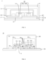
- An embodiment of the present application provides a sound collection device 1, which has a schematic structure as shown in FIGS. 3-5 , and includes: a housing 20 and a silicon-based microphone device 10 located within the housing 20.
- the silicon-based microphone device 10 includes a circuit board 100 and an even number of silicon-based microphone chips provided on one side of the circuit board 100.
- the circuit board 100 is provided with at least one sound inlet hole 110, and the at least one sound inlet hole 100 is communicated with to a back cavity 303 of portion of the even number of silicon-based microphone chips in one-to-one correspondence.
- the housing 20 is provided with a sound channel in communication with the sound inlet hole 110 in one-to-one correspondence.
- the correspondingly communicated back cavity 303a, sound inlet hole 110, and sound channel may form a first acoustic cavity; and, the back cavity 303b may form a second acoustic cavity.
- the first acoustic cavity has a different volume and/or shape from that of the second acoustic cavity.
- the sound collection device 1 uses the even number of silicon-based microphone chips to collect ambient sound.
- the first and second acoustic cavities have different volumes and/or shapes.
- the back cavity 303a, the sound inlet hole 110, and the partition plate aperture 51 form the first acoustic cavity
- the back cavity 303b forms the second acoustic cavity.
- the two acoustic cavities have different volumes and/or shapes.
- the back cavity 303a, the sound inlet hole 110, the partition plate aperture 51 and the housing aperture 21 form the first acoustic cavity
- the back cavity 303b forms the second acoustic cavity.
- the two acoustic cavities have different volumes and/or shapes.
- the back cavity 303a, the sound inlet hole 110, the partition plate sink 52, and the housing aperture 21 form the first acoustic cavity
- the back cavity 303b forms the second acoustic cavity.
- the two acoustic cavities have different volumes and/or shapes.
- the difference in volume and/or shape of the two acoustic cavities may contribute to generation of a path difference in the aforementioned first and second acoustic cavities for the near-field sound in the ambient sound. That is, the near-field sound acts on the corresponding two silicon-based microphone chips with a different amplitude or phase, and thus the near-field sound on the corresponding two silicon-based microphone chips may not be counteracted each other.
- the far-field sound in the ambient sound does not generate a significant path difference in the aforementioned first and second acoustic cavities. That is, the far-field sound acts on the corresponding two silicon-based microphone chips with a same amplitude or phase, and thus the far-field sound on the corresponding two silicon-based microphone chips may be counteracted each other. Therefore, the sound collection device 1 provided in the embodiment of the present application may more easily output only the near-field audio reference signal according to the collected ambient sound, or more easily output only the near-field audio reference signal with the cooperation of other signal processing apparatus.
- the present application provides a possible implementation for the housing 20 of the sound collection device 1 as follows.
- the housing 20 includes a cover plate 30, a wall plate 40, and a partition plate 50.
- the cover plate 30 is coupled to the wall plate 40 to form a sound isolation chamber 22.
- the partition plate 50 is connected between the circuit board 100 and an inner wall of the cover plate 30. Or, the partition plate 50 is connected between the circuit board 100 and an inner wall of the wall plate 40.
- the partition plate 50 is provided with at least one partition plate aperture 51 constituting the sound channel.
- the partition plate aperture 51 is communicated with the at least one sound inlet hole 110.
- the cover plate 30 is coupled to the wall plate 40 of the housing 20 to form the sound isolation chamber 22 that may be used to accommodate the silicon-based microphone device 10.
- the partition plate 50 of the housing 20 may provide a mounting position for the silicon-based microphone device 10.
- the partition plate aperture 51 provided on the partition plate 50 may constitute the sound channel of the housing 20 that is communicated with the sound inlet hole 110 in one-to-one correspondence. That is, the partition plate aperture 51 may form at least part of the sound channel. Moreover, the partition plate aperture 51 is communicated with the at least one sound inlet hole 110, so as to contribute to generation of distinction, i.e., difference in volume and/or shape for the first and second acoustic cavities.
- the first acoustic cavity includes the back cavity 303, the sound inlet hole 110 and the sound channel (which includes at least the partition plate aperture 51) correspondingly communicated, and the second acoustic cavity includes the back cavity 303 correspondingly communicated.
- the sound inlet hole 110 and the sound channel which includes at least the partition plate aperture 51
- the second acoustic cavity includes the back cavity 303 correspondingly communicated.
- the cover plate 30 or the wall plate 40 is provided with at least one housing aperture 21.
- the housing aperture 21 is communicated with the at least one partition plate aperture 51.
- the cover plate 30 or the wall plate 40 of the housing 20 is provided with the housing aperture 21, which may be communicated with the partition plate aperture 51. That is, the housing aperture 21 may also form a part of the sound channel.
- the housing aperture 21 may contribute to generation of distinction, i.e., difference in volume and/or shape for the first and second acoustic cavities.
- the housing aperture 21 may contribute to the ambient sound entering the acoustic cavities directly through air propagation and eventually acting on the silicon-based microphone chips.
- the first acoustic cavity includes the back cavity 303a and the sound inlet hole 110 correspondingly communicated, or includes the back cavity 303a, the sound inlet hole 110 and the sound channel (which includes the partition plate aperture 51) correspondingly communicated, or includes the back cavity 303a, the sound inlet hole 110 and the sound channel (which includes the partition plate aperture 51 and the housing aperture 21) correspondingly communicated; and the second acoustic cavity includes the back cavity 303b.
- the second acoustic cavity includes the back cavity 303b.
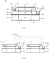
- the present application provides another possible implementation for the housing 20 of the sound collection device 1 as follows.
- the housing 20 includes a cover plate 30, a wall plate 40 and a partition plate 50.
- the cover plate 30 is coupled to the wall plate 40 to form a sound insulation chamber 22.
- the partition plate 50 is connected between an inner wall of the cover plate 30 and a part of the circuit board 100. Or, the partition plate 50 is connected between an inner wall of the wall plate 40 and a part of the circuit board 100.
- the partition plate 50 is provided with at least one partition plate sink 52 constituting to the sound channel.
- One end of the partition plate sink 52 is communicated with the at least one sound inlet hole 110.
- the other end of the partition plate sink 52 is communicated with the sound isolation chamber 22.
- the cover plate 30 is coupled to the wall plate 40 of the housing 20 to form the sound isolation chamber 22 that may be used to accommodate the silicon-based microphone device 10.
- the partition plate 50 of the housing 20 may provide a mounting position for the silicon-based microphone device 10.
- the partition plate sink 52 provided in the partition plate 50 may constitute the sound channel of the housing 20 that is communicated with the sound inlet hole 110 in one-to-one correspondence.
- the other end of the partition plate sink 52 is communicated with the sound isolation cavity 22. That is, both of the partition plate sink 52 and the sound isolation cavity 22 may form at least part of the sound channel.
- the partition plate sink 52 is communicated with the at least one sound inlet hole 110, so as to contribute to generation of distinction, i.e., difference in volume and/or shape for the first and second acoustic cavities.
- the first acoustic cavity includes the back cavity 303a, the sound inlet hole 110 and the sound channel (which includes at least the partition plate sink 52 and the sound isolation cavity 22) correspondingly communicated, and the second acoustic cavity includes the back cavity 303b correspondingly communicated.
- the sound inlet hole 110 and the sound channel which includes at least the partition plate sink 52 and the sound isolation cavity 22
- the second acoustic cavity includes the back cavity 303b correspondingly communicated.
- the cover plate 30 or the wall plate 40 is provided with at least one housing aperture 21.
- the housing aperture 21 is communicated with the sound isolation cavity 22.
- the cover plate 30 or the wall plate 40 of the housing 20 is provided with the housing aperture 21 and this housing aperture 21 may be communicated with the sound isolation cavity 22. That is, the housing aperture 21 may also constitute a part of the sound channel.
- the housing aperture 21 may also constitute a part of the sound channel.
- the present application provides a possible implementation for the housing 20 of the sound collection device 1 as follows.
- At least two of aperture diameter of the sound inlet hole 110, aperture diameter of the partition plate aperture 51 and aperture diameter of the housing aperture 21 according to the present application embodiment have different sizes.
- difference in volume and/or shape of the first and second acoustic cavities are easily generated by changing sizes of aperture diameter of apertures constituting the sound channel.
- the sound collection device 1 collects the ambient sound
- the sound collection device 1 may obtain a near-field audio reference signal directly by using its own structure, workload of subsequent signal processing apparatus such as the echo processor 2 may be reduced. Therefore, the present application provides a possible implementation for the silicon-based microphone device 10 in the sound collection device 1 as follows.
- the silicon-based microphone chip according to an embodiment of the present application is a differential silicon-based microphone chip 300.
- a first microphone structure of one differential silicon-based microphone chip 300 may be electrically connected to a second microphone structure of the other differential silicon-based microphone chip 300, and a second microphone structure of the one differential silicon-based microphone chip 300 may be electrically connected to a first microphone structure of the other differential silicon-based microphone chip 300.
- differential silicon-based microphone chips 300 are used for acousto-electric conversion.
- the silicon-based microphone device in FIG. 6 is only exemplified as two differential silicon-based microphone chips 300.
- a first microphone structure 301 and a second microphone structure 302 of each differential silicon-based microphone chip 300 may respectively generate electrical signals with the same variation amplitude and opposite sign. Therefore, in an embodiment of the present application, a first microphone structure 301a of a first differential silicon-based microphone chip is electrically connected to a second microphone structure 302b of a second differential silicon-based microphone chip 300b, and a second microphone structure 302a of the first differential silicon-based microphone chip 300a is electrically connected to a first microphone structure 301b of the second differential silicon-based microphone chip.
- a first sound wave electrical signal generated by the first differential silicon-based microphone chip 300a may be superimposed with the second sound wave electrical signal generated by the second differential silicon-based microphone chip 300b. In this way, the homologous sound wave signals with the same variation amplitude and the opposite sign in the first sound wave electrical signal and the second sound wave electrical signal may be partially weakened or counteracted.
- one differential silicon-based microphone chip 300 collects ambient sound waves through a corresponding acoustic cavity (which includes the back cavity 303 of the one differential silicon-based microphone chip 300 itself, the corresponding sound inlet hole 110 on the circuit board 100, and the corresponding sound channel in the housing 20), and the other differential silicon-based microphone chip 300 collects ambient sound waves through another corresponding acoustic cavity (which includes the back cavity 303 of the other differential silicon-based microphone chip 300 itself).
- the first and second acoustic cavities Due to the different volumes and/or shapes of the first and second acoustic cavities, it may contribute to generation of a path difference in the aforementioned first and second sound cavities for the near-field sound in the ambient sound. That is, the near-field sound acts on the corresponding two silicon-based microphone chips with a different amplitude or phase. At this time, the near-field audio signals generated by the two silicon-based microphone chips will be mutually attenuated after being superimposed, but will not be completely counteracted. Meanwhile, the far-field sound in the ambient sound does not generate a significant path difference in the aforementioned first and second sound cavities. That is, it may deem that the far-field sound acts on the corresponding two silicon-based microphone chips with a same amplitude or phase. At this time, the far-field audio signals generated by the two silicon-based microphone chips will be completely counteracted each other after being superposed.
- the silicon-based microphone device may employ an even number of differential silicon-based microphone chips, and may output only the near-field audio reference signal directly through its own structure according to the collected ambient sound.
- the differential silicon-based microphone chip 300 is fixedly connected to the circuit board 100 via, for example, silicone.
- the differential silicon-based microphone chip 300 may further include an upper back plate 310, a semiconductor diaphragm 330, and a lower back plate 320 that are stacked and disposed spaced apart from each other. Specifically, a gap, such as an air gap, is disposed between the upper back plate 310 and the semiconductor diaphragm 330 and between the semiconductor diaphragm 330 and the lower back plate 320.
- the upper back plate 310 and the semiconductor diaphragm 330 constitute the body of the first microphone structure 301.
- the semiconductor diaphragm 330 and the lower back plate 320 constitute the body of the second microphone structure 302.
- Portions of the upper back plate 310 and the lower back plate 320 corresponding to the sound inlet hole are provided with a number of airflow holes.
- one back plate in the differential silicon-based microphone chip 300 away from the circuit board 100 is defined as the upper back plate 310, and one back plate in the differential silicon-based microphone chip 300 close to the circuit board 100 is defined as the lower back plate 320 herein.
- the semiconductor diaphragm 330 is shared by the first microphone structure 301 and the second microphone structure 302.
- the semiconductor diaphragm 330 may be a thinner and more flexible structure that may be bent and deformed under the action of sound waves.
- Both the upper back plate 310 and the lower back plate 320 may be a much thicker and more rigid structure than the semiconductor diaphragm 330, which is less prone to deformation.
- the semiconductor diaphragm 330 and the upper back plate 310 may be arranged in parallel and separated by an upper air gap 313, thereby forming the body of the first microphone structure 301.
- the semiconductor diaphragm 330 and the lower back plate 320 may be arranged in parallel and separated by a lower air gap 323, thereby forming the body of the second microphone structure 302.
- an electric field (which is non-conductive) may be formed between the semiconductor diaphragm 330 and the upper back plate 310 and between the semiconductor diaphragm 330 and the lower back plate 320. Sound waves entering from the sound inlet hole may contact the semiconductor diaphragm 330 through the back cavity 303, a lower airflow hole 321 in the lower back plate 320.
- the semiconductor diaphragm 330 When the sound waves enter the back cavity 303 of the differential silicon-based microphone chip 300, the semiconductor diaphragm 330 may be deformed under the action of the sound waves.
- the changes of the gaps between the semiconductor diaphragm 330 and the upper back plate 310 and the lower back plate 320 caused by the deformation may bring about the change of the capacitance between the semiconductor diaphragm 330 and the upper back plate 310, and the change of the capacitance between the semiconductor diaphragm 330 and the lower back plate 320, that is, the conversion of sound waves into electrical signals is realized.
- an upper electric field may be formed in the gap between the semiconductor diaphragm 330 and the upper back plate 310 by applying a bias voltage between the semiconductor diaphragm 330 and the upper back plate 310.
- a lower electric field may be formed in the gap between the semiconductor diaphragm 330 and the lower back plate 320 by applying a bias voltage between the semiconductor diaphragm 330 and the lower back plate 320. Due to the polarities of the upper and lower electric fields being exactly opposite, when the semiconductor diaphragm 330 is bent upward and downward under the action of sound waves, the amount of capacitance change of the first microphone structure 301 has the same magnitude and opposite sign as that of the second microphone structure 302.
- the semiconductor diaphragm 330 may be made of polycrystalline silicon material.
- the thickness of the semiconductor diaphragm 330 is not more than 1 ⁇ m, which may be deformed even when is under a small action of sound waves and thus has a high sensitivity.
- Each of the upper back plate 310 and the lower back plate 320 may be made of a rigid material having a thickness of several microns.
- the gap between the semiconductor diaphragm 330 and the upper back plate 310 or the lower back plate 320 has a thickness of a few microns, i.e., in a micron level, respectively.
- every two differential silicon-based microphone chips 300 may include a first differential silicon-based microphone chip 300a and a second differential silicon-based microphone chip 300b.
- the first upper back plate 310a of the first differential silicon-based microphone chip 300a may be electrically connected to the second lower back plate 320b of the second differential silicon-based microphone chip 300b for forming a first path signal.
- the first lower back plate 320a of the first differential silicon based microphone chip 300a may be electrically connected to the second upper back plate 310b of the second differential silicon based microphone chip 300b for forming a second path signal.
- the amount of capacitance change of the first microphone structure 301 has the same magnitude and opposite sign as that of the second microphone structure 302.
- the capacitance changes at the upper back plate 310 of one differential silicon microphone chip 300 and the lower back plate 320 of the other differential silicon microphone chip 300 are the same in magnitude and opposite in sign.
- a first upper sound wave electrical signal generated at the first upper back plate 310a of the first differential silicon-based microphone chip 300a is superimposed with a second lower sound wave electrical signal generated at the second lower back plate 320b of the second differential silicon-based microphone chip 300b to obtain a first path signal.
- Homologous audio signals in the first upper sound wave electrical signal and the second lower sound wave electrical signal may be attenuated or counteracted each other.
- a first lower sound wave electrical signal generated at the first lower back plate 320a of the first differential silicon-based microphone chip 300a is superimposed with a second upper sound wave electrical signal generated at the second upper back plate 310b of the second differential silicon-based microphone chip 300b to obtain a second path signal.
- Homologous audio signals in the first lower sound wave electrical signal and the second lower sound wave electrical signal may be attenuated or counteracted each other.
- the upper back plate electrode 312a of the first upper back plate 310a may be electrically connected to the lower back plate electrode 322b of the second lower back plate 320b via a wire 380, for forming the first path signal.
- the lower back plate electrode 322a of the first lower back plate 320a may be electrically connected to the upper back plate electrode 312b of the second upper back plate 310b via the wire 380, for forming the second path signal.
- the first semiconductor diaphragm 330a of the first differential silicon-based microphone chip 300a is electrically connected to the second semiconductor diaphragm 330b of the second differential silicon-based microphone chip 300b. At least one of the first semiconductor diaphragm 330a and the second semiconductor diaphragm 330b is used to electrically connect to a constant voltage source.
- the first semiconductor diaphragm 330a of the first differential silicon-based microphone chip 300a is electrically connected to the second semiconductor diaphragm 330b of the second differential silicon-based microphone chip 300b, thereby allowing that the semiconductor diaphragms 330 of the two differential silicon-based microphone chips 300 may have the same potential. That is, a reference for generating electrical signals by the two differential silicon-based microphone chips 300 may be unified.
- the semiconductor diaphragm electrode 331a of the first semiconductor diaphragm, and the semiconductor diaphragm electrode 331b of the second semiconductor diaphragm may be electrically connected via the wire 380.
- the semiconductor diaphragms 330 of all differential silicon-based microphone chips 300 may be electrically connected, so that the references for generating the electrical signals by differential silicon-based microphone chips 300 are the same.
- the silicon-based microphone device may further include a control chip 400.
- the control chip 400 is located within the shielding cavity 210 and is electrically connected to the circuit board 100.
- One of the first upper back plate 310a and the second lower back plate 320b may be electrically connected to one of the signal input terminals of the control chip 400.
- One of the first lower back plate 320a and the second upper back plate 310b may be electrically connected to another one of the signal input terminals of the control chip 400.
- control chip 400 is used to receive signals in two paths that have been physically de-noised from each of the aforementioned differential silicon-based microphone chips 300. And the signals in the two paths may be secondary de-noised and then output to the next level device or component.
- control chip 400 is fixedly connected to the circuit board 100 by, for example, silicone or red glue.
- the control chip 400 includes an Application Specific Integrated Circuit (ASIC) chip.
- the ASIC chip may apply a differential amplifier with two input terminals.
- output signal of the ASIC chip may be single-ended or differential outputs.
- the differential silicon-based microphone chip 300 includes a silicon substrate 340.
- the first microphone structure 301 and the second microphone structure 302 are laminated and provided on one side of the silicon substrate 340.
- the silicon substrate 340 has a through-hole 341 thereon for forming the back cavity 303.
- the through-hole 341 corresponds to both of the first microphone structure 301 and the second microphone structure 302.
- the silicon substrate 340 is fixedly connected to the circuit board 100 on a side away from the first microphone structure 301 and the second microphone structure 302.
- the through-hole 341 is communicated to the sound inlet hole.
- the silicon substrate 340 provides support for the first microphone structure 301 and the second microphone structure 302.
- the silicon substrate 340 has a through-hole 341 for forming the back cavity 303, which may facilitate the entry of sound waves into the differential silicon-based microphone chip 300 and the sound waves may act on the first microphone structure 301 and the second microphone structure 302, respectively, causing the first microphone structure 301 and the second microphone structure 302 to generate differential electrical signals.
- the differential silicon-based microphone chip 300 may further include a first insulating layer 350, a second insulating layer 360, and a third insulating layer 370 which are patterned.
- the silicon substrate 340, the first insulating layer 350, the lower back plate 320, the second insulating layer 360, the semiconductor diaphragm 330, the third insulating layer 370, and the upper back plate 310, are provided to be stacked sequentially.
- the lower back plate 320 is separated from the silicon substrate 340 by the patterned first insulating layer 350
- the semiconductor diaphragm 330 is separated from the lower back plate 320 by the patterned second insulating layer 360
- the upper back plate 310 is separated from the semiconductor diaphragm 330 by the patterned third insulating layer 370, thus forming an electrical isolation between the conductive layers, so as to avoid a short circuit between the conductive layers and signal accuracy degradation.
- each of the first insulating layer 350, the second insulating layer 360, and the third insulating layer 370 may be patterned by an etching process, after full film formation, to remove portions of the insulating layer corresponding to the area of the through hole 341 and portions of the insulating layer in the area used to prepare the electrodes.
- the silicon-based microphone device may further include a shielding case 200.
- the shielding case 200 covers one side of the circuit board 100 and forms a shielding cavity 210 with the circuit board 100.
- An even number of differential silicon-based microphone chips are located within the shielding cavity 210.
- the shielding case 200 is coupled to the circuit board 100 to form a relatively closed shielding cavity 210.
- the shielding case 200 may include a metal housing electrically connected to the circuit board 100.
- the shielding case 200 is fixedly connected to one side of the board 100 by, for example, solder paste or conductive adhesive.
- the circuit board 100 includes a Printed Circuit Board (PCB) 100 board.
- PCB Printed Circuit Board
- the silicon-based microphone device in the above embodiments of the present application may employ a differential structure having a single diaphragm (e.g., a semiconductor diaphragm), and a dual back plate (e.g., an upper back plate and a lower back plate), or employ a differential structure having a dual diaphragm and a single back plate, or some other differential structure.
- a differential structure having a single diaphragm e.g., a semiconductor diaphragm
- a dual back plate e.g., an upper back plate and a lower back plate
- a sound processing method includes steps S101-S103.
- a real-time near-field audio reference signal is obtained by using any of the sound collection device 1 according to the above embodiments. Thereafter, the step S103 is performed.
- the sound collection device 1 may collect the ambient sound and perform an acousto-electric conversion on the ambient sound. Thereafter, the real-time near-field audio reference signal may be obtained directly by using the own structure of the sound collection device 1. Alternatively, the real-time near-field audio reference signal may be obtained by performing signal processing on the acousto-electric conversed audio signal from the sound collection device 1, for example, by the echo processor 2.
- the ambient sound may be collected by a conventional microphone and converted into a mixed audio signal through the acousto-electric conversion.
- a real-time far-field audio signal is obtained by removing the real-time near-field audio signal from the real-time mixed audio signal according to the real-time near-field audio reference signal.
- the echo processor 2 may use the real-time near-field audio reference signal obtained in step S101 as a noise reference signal, which may more easily and accurately remove the real-time near-field audio signal from the mixed audio signal to obtain the far-field audio signal, greatly improving the accuracy of the far-field audio signal.
- a sound processing apparatus 500 which has a structural framework schematically shown in FIG. 10 , includes an audio signal obtaining module 510 and an audio signal processing module 520.
- the audio signal obtaining module 510 is configured to collect a real-time near-field audio reference signal and a real-time mixed audio signal.
- the audio signal processing module 520 is configured to remove a real-time near-field audio signal from the real-time mixed audio signal according to the real-time near-field audio reference signal to obtain a real-time far-field audio signal.
- the sound processing apparatus of the embodiment may perform any of the sound processing methods according to the embodiments of the present application, and the principles of their implementation are similar and will not be repeated here.
- an embodiment of the present application provides a computer-readable storage medium.
- the computer-readable storage medium has a computer program stored thereon.
- the computer program is executed by an electronic device, the sound processing methods according to the above embodiments may be realized.
- the near-field audio signal in the mixed audio signal is more easily and more accurately to be removed, so as to obtain the far-field audio signal, thus the accuracy of the far-field audio signal is greatly improved.
- the computer-readable storage media may be any usable media that may be accessed by an electronic device, including a volatile and non-volatile media, a removable media or an non-removable media.
- the computer-readable storage media includes, but is not limited to, any type of disks (including floppy disk, hard disk, CD-ROM, CD-ROM, and magnetic disk), ROM, RAM, Erasable Programmable Read-Only Memory (EPROM), Electrically Erasable Programmable Read Only Memory (EEPROM), flash memory, magnetic card, or light card. That is, the computer-readable storage media includes any media on which information is stored or transmitted by a device (for example, a computer) in a form capable of being read.
- a device for example, a computer
- the electronic device may include a transceiver.
- the transceiver may be used for receiving and transmitting a signal.
- the transceiver may allow the electronic device to communicate wirelessly or wired with other devices to exchange data. It is noted that the transceiver is not limited to one in practical applications.
- the electronic device may further include an input unit.
- the input unit may be used to receive an input digital, character, image, and/or sound information, or to generate a key signal input related to a user setting and functional control of the electronic device.
- the input unit may include, but is not limited to, one or more of a touch screen, physical keyboard, function key (e.g., volume control button, switch button, etc.), trackball, mouse, joystick, shooting device, sound pickup, etc.
- the electronic device may further include an output unit.
- the output unit may be used to output or display information that has been processed by a processor.
- the output unit may include, but is not limited to, one or more of a display device, a speaker 5, a vibration device, etc.
- the computer-readable storage medium according to an embodiment of the present application is suitable for various optional implementations of any of the above sound processing methods, which is not repeated herein.
- steps, measures, and schemes in the operations, methods, and process already discussed in the present application may be alternated, changed, combined, or deleted. Further, other steps, measures, and schemes in the operations, methods, and process already discussed in the present application may also be alternated, changed, rearranged, disassembled, combined, or deleted. Further, steps, measures, and schemes in the operations, methods, and process of the prior art having the same disclosed in the present application may also be alternated, changed, rearranged, disassembled, combined, or deleted.
- first and second are used for descriptive purposes only, and are not to be construed as indicating or implying relative importance or implicitly specifying the number of technical features indicated. Thus, features limited with “first” and “second” may explicitly or implicitly include one or more such features. In the description of the present application, unless otherwise specified, "a plurality of" means two or more.
Landscapes
- Physics & Mathematics (AREA)
- Engineering & Computer Science (AREA)
- Acoustics & Sound (AREA)
- Signal Processing (AREA)
- Health & Medical Sciences (AREA)
- General Health & Medical Sciences (AREA)
- Otolaryngology (AREA)
- Circuit For Audible Band Transducer (AREA)
- Measurement Of Velocity Or Position Using Acoustic Or Ultrasonic Waves (AREA)
- Electrophonic Musical Instruments (AREA)
- Geophysics And Detection Of Objects (AREA)
- Electrostatic, Electromagnetic, Magneto- Strictive, And Variable-Resistance Transducers (AREA)
Applications Claiming Priority (2)
| Application Number | Priority Date | Filing Date | Title |
|---|---|---|---|
| CN202010694656.3A CN113949976B (zh) | 2020-07-17 | 2020-07-17 | 声音采集装置、声音处理设备及方法、装置、存储介质 |
| PCT/CN2021/076948 WO2022012043A1 (zh) | 2020-07-17 | 2021-02-19 | 声音采集装置、声音处理设备及方法、装置、存储介质 |
Publications (1)
| Publication Number | Publication Date |
|---|---|
| EP4156715A1 true EP4156715A1 (de) | 2023-03-29 |
Family
ID=79326778
Family Applications (1)
| Application Number | Title | Priority Date | Filing Date |
|---|---|---|---|
| EP21841786.3A Withdrawn EP4156715A1 (de) | 2020-07-17 | 2021-02-19 | Audioerfassungsvorrichtung, audioverarbeitungsvorrichtung, verfahren, vorrichtung und speichermedium |
Country Status (7)
| Country | Link |
|---|---|
| US (1) | US20230319468A1 (de) |
| EP (1) | EP4156715A1 (de) |
| JP (1) | JP2023533340A (de) |
| KR (1) | KR20230018516A (de) |
| CN (2) | CN113949979A (de) |
| TW (1) | TWI807285B (de) |
| WO (1) | WO2022012043A1 (de) |
Families Citing this family (2)
| Publication number | Priority date | Publication date | Assignee | Title |
|---|---|---|---|---|
| CN114205722A (zh) * | 2020-09-17 | 2022-03-18 | 通用微(深圳)科技有限公司 | 硅基麦克风装置及电子设备 |
| KR102596175B1 (ko) * | 2023-03-21 | 2023-10-31 | (주)에이넷솔루션 | 소음 공해가 없는 스마트알람장치를 제공하는 방법 |
Family Cites Families (25)
| Publication number | Priority date | Publication date | Assignee | Title |
|---|---|---|---|---|
| JP5088950B2 (ja) * | 2006-11-22 | 2012-12-05 | 株式会社船井電機新応用技術研究所 | 集積回路装置及び音声入力装置、並びに、情報処理システム |
| JP2008199226A (ja) * | 2007-02-09 | 2008-08-28 | Yamaha Corp | コンデンサマイク装置 |
| US8175291B2 (en) * | 2007-12-19 | 2012-05-08 | Qualcomm Incorporated | Systems, methods, and apparatus for multi-microphone based speech enhancement |
| US8831936B2 (en) * | 2008-05-29 | 2014-09-09 | Qualcomm Incorporated | Systems, methods, apparatus, and computer program products for speech signal processing using spectral contrast enhancement |
| CN201226594Y (zh) * | 2008-07-04 | 2009-04-22 | 瑞声声学科技(深圳)有限公司 | 硅基电容式麦克风 |
| CN101321413B (zh) * | 2008-07-04 | 2012-03-28 | 瑞声声学科技(深圳)有限公司 | 电容式麦克风 |
| JP5434798B2 (ja) * | 2009-12-25 | 2014-03-05 | 船井電機株式会社 | マイクロホンユニット、及び、それを備えた音声入力装置 |
| US9497544B2 (en) * | 2012-07-02 | 2016-11-15 | Qualcomm Incorporated | Systems and methods for surround sound echo reduction |
| CN104602171A (zh) * | 2013-10-30 | 2015-05-06 | 北京卓锐微技术有限公司 | 一种集成的硅电容麦克风 |
| CN103702258B (zh) * | 2013-12-27 | 2017-02-22 | 深圳泰山在线科技有限公司 | 麦克风装置及消除近场声源干扰的麦克风设置方法 |
| US9955246B2 (en) * | 2014-07-03 | 2018-04-24 | Harman International Industries, Incorporated | Gradient micro-electro-mechanical systems (MEMS) microphone with varying height assemblies |
| US9712915B2 (en) * | 2014-11-25 | 2017-07-18 | Knowles Electronics, Llc | Reference microphone for non-linear and time variant echo cancellation |
| CN104902414A (zh) * | 2015-05-29 | 2015-09-09 | 歌尔声学股份有限公司 | 一种mems麦克风元件及其制造方法 |
| CN204652659U (zh) * | 2015-05-29 | 2015-09-16 | 歌尔声学股份有限公司 | 一种差分电容式mems麦克风 |
| US9953628B1 (en) * | 2016-10-24 | 2018-04-24 | Merry EIectronics (Shenzhen) Co., Ltd. | Microphone device |
| CN106657700B (zh) * | 2017-01-11 | 2019-12-10 | 广州广有通信设备有限公司 | 一种能消除回声的免提通话装置及其控制方法 |
| GB201709851D0 (en) * | 2017-06-20 | 2017-08-02 | Nokia Technologies Oy | Processing audio signals |
| CN107835477B (zh) * | 2017-11-24 | 2020-03-17 | 歌尔股份有限公司 | 一种mems麦克风 |
| US10264348B1 (en) * | 2017-12-29 | 2019-04-16 | Nvf Tech Ltd | Multi-resonant coupled system for flat panel actuation |
| GB2573173B (en) * | 2018-04-27 | 2021-04-28 | Cirrus Logic Int Semiconductor Ltd | Processing audio signals |
| CN108711433B (zh) * | 2018-05-18 | 2020-08-14 | 歌尔科技有限公司 | 一种回声消除方法和装置 |
| CN208461997U (zh) * | 2018-06-29 | 2019-02-01 | 歌尔科技有限公司 | 拾音器及拾音设备 |
| CN110677802B (zh) * | 2018-07-03 | 2022-05-13 | 百度在线网络技术(北京)有限公司 | 用于处理音频的方法和装置 |
| CN109068250B (zh) * | 2018-10-15 | 2021-01-08 | 维沃移动通信有限公司 | 一种麦克风和电子设备 |
| CN210839669U (zh) * | 2020-01-10 | 2020-06-23 | 北京小米移动软件有限公司 | 终端设备 |
-
2020
- 2020-07-17 CN CN202110541970.2A patent/CN113949979A/zh active Pending
- 2020-07-17 CN CN202010694656.3A patent/CN113949976B/zh active Active
-
2021
- 2021-02-19 WO PCT/CN2021/076948 patent/WO2022012043A1/zh unknown
- 2021-02-19 JP JP2023501507A patent/JP2023533340A/ja active Pending
- 2021-02-19 US US18/004,993 patent/US20230319468A1/en active Pending
- 2021-02-19 KR KR1020237000077A patent/KR20230018516A/ko unknown
- 2021-02-19 EP EP21841786.3A patent/EP4156715A1/de not_active Withdrawn
- 2021-03-23 TW TW110110372A patent/TWI807285B/zh active
Also Published As
| Publication number | Publication date |
|---|---|
| KR20230018516A (ko) | 2023-02-07 |
| JP2023533340A (ja) | 2023-08-02 |
| CN113949976A (zh) | 2022-01-18 |
| US20230319468A1 (en) | 2023-10-05 |
| CN113949979A (zh) | 2022-01-18 |
| CN113949976B (zh) | 2022-11-15 |
| TW202205263A (zh) | 2022-02-01 |
| WO2022012043A1 (zh) | 2022-01-20 |
| TWI807285B (zh) | 2023-07-01 |
Similar Documents
| Publication | Publication Date | Title |
|---|---|---|
| EP4156715A1 (de) | Audioerfassungsvorrichtung, audioverarbeitungsvorrichtung, verfahren, vorrichtung und speichermedium | |
| CN212259333U (zh) | 硅基麦克风装置及电子设备 | |
| EP4164246A1 (de) | Tonerfassungsvorrichtung, tonverarbeitungsvorrichtung und -verfahren, vorrichtung und speichermedium | |
| TWI790575B (zh) | 矽基麥克風裝置及電子設備 | |
| TWI790574B (zh) | 矽基麥克風裝置及電子設備 | |
| TWI790578B (zh) | 矽基麥克風裝置及電子設備 | |
| CN113784265B (zh) | 硅基麦克风装置及电子设备 | |
| WO2022057199A1 (zh) | 硅基麦克风装置及电子设备 |
Legal Events
| Date | Code | Title | Description |
|---|---|---|---|
| STAA | Information on the status of an ep patent application or granted ep patent |
Free format text: STATUS: THE INTERNATIONAL PUBLICATION HAS BEEN MADE |
|
| PUAI | Public reference made under article 153(3) epc to a published international application that has entered the european phase |
Free format text: ORIGINAL CODE: 0009012 |
|
| STAA | Information on the status of an ep patent application or granted ep patent |
Free format text: STATUS: REQUEST FOR EXAMINATION WAS MADE |
|
| 17P | Request for examination filed |
Effective date: 20221221 |
|
| AK | Designated contracting states |
Kind code of ref document: A1 Designated state(s): AL AT BE BG CH CY CZ DE DK EE ES FI FR GB GR HR HU IE IS IT LI LT LU LV MC MK MT NL NO PL PT RO RS SE SI SK SM TR |
|
| RIC1 | Information provided on ipc code assigned before grant |
Ipc: H04R 19/04 20060101AFI20230904BHEP |
|
| DAV | Request for validation of the european patent (deleted) | ||
| DAX | Request for extension of the european patent (deleted) | ||
| STAA | Information on the status of an ep patent application or granted ep patent |
Free format text: STATUS: THE APPLICATION HAS BEEN WITHDRAWN |
|
| 18W | Application withdrawn |
Effective date: 20231108 |