EP4156652A1 - Video load balancing system for a peer-to-peer server network - Google Patents
Video load balancing system for a peer-to-peer server network Download PDFInfo
- Publication number
- EP4156652A1 EP4156652A1 EP22197710.1A EP22197710A EP4156652A1 EP 4156652 A1 EP4156652 A1 EP 4156652A1 EP 22197710 A EP22197710 A EP 22197710A EP 4156652 A1 EP4156652 A1 EP 4156652A1
- Authority
- EP
- European Patent Office
- Prior art keywords
- server
- peer
- hosting
- self
- monitoring
- Prior art date
- Legal status (The legal status is an assumption and is not a legal conclusion. Google has not performed a legal analysis and makes no representation as to the accuracy of the status listed.)
- Pending
Links
- 238000012544 monitoring process Methods 0.000 claims abstract description 120
- 238000004891 communication Methods 0.000 claims abstract description 77
- 238000000034 method Methods 0.000 claims description 48
- 230000004044 response Effects 0.000 abstract description 13
- 230000036541 health Effects 0.000 description 11
- 230000006870 function Effects 0.000 description 7
- 230000003139 buffering effect Effects 0.000 description 6
- 238000010586 diagram Methods 0.000 description 5
- 230000008859 change Effects 0.000 description 4
- 238000012546 transfer Methods 0.000 description 3
- 230000008878 coupling Effects 0.000 description 2
- 238000010168 coupling process Methods 0.000 description 2
- 238000005859 coupling reaction Methods 0.000 description 2
- 238000012423 maintenance Methods 0.000 description 2
- 230000000737 periodic effect Effects 0.000 description 2
- 230000008569 process Effects 0.000 description 2
- 230000003213 activating effect Effects 0.000 description 1
- 230000036772 blood pressure Effects 0.000 description 1
- 230000003247 decreasing effect Effects 0.000 description 1
- 238000011156 evaluation Methods 0.000 description 1
- 238000012986 modification Methods 0.000 description 1
- 230000004048 modification Effects 0.000 description 1
- 238000012806 monitoring device Methods 0.000 description 1
- 230000004297 night vision Effects 0.000 description 1
- 230000000474 nursing effect Effects 0.000 description 1
- 238000012545 processing Methods 0.000 description 1
- 238000001931 thermography Methods 0.000 description 1
- 230000007704 transition Effects 0.000 description 1
Images


Classifications
-
- H—ELECTRICITY
- H04—ELECTRIC COMMUNICATION TECHNIQUE
- H04L—TRANSMISSION OF DIGITAL INFORMATION, e.g. TELEGRAPHIC COMMUNICATION
- H04L67/00—Network arrangements or protocols for supporting network services or applications
- H04L67/01—Protocols
- H04L67/10—Protocols in which an application is distributed across nodes in the network
- H04L67/1001—Protocols in which an application is distributed across nodes in the network for accessing one among a plurality of replicated servers
- H04L67/1004—Server selection for load balancing
- H04L67/1008—Server selection for load balancing based on parameters of servers, e.g. available memory or workload
-
- H—ELECTRICITY
- H04—ELECTRIC COMMUNICATION TECHNIQUE
- H04L—TRANSMISSION OF DIGITAL INFORMATION, e.g. TELEGRAPHIC COMMUNICATION
- H04L67/00—Network arrangements or protocols for supporting network services or applications
- H04L67/01—Protocols
- H04L67/10—Protocols in which an application is distributed across nodes in the network
- H04L67/1001—Protocols in which an application is distributed across nodes in the network for accessing one among a plurality of replicated servers
-
- A—HUMAN NECESSITIES
- A61—MEDICAL OR VETERINARY SCIENCE; HYGIENE
- A61B—DIAGNOSIS; SURGERY; IDENTIFICATION
- A61B5/00—Measuring for diagnostic purposes; Identification of persons
- A61B5/0002—Remote monitoring of patients using telemetry, e.g. transmission of vital signals via a communication network
- A61B5/0004—Remote monitoring of patients using telemetry, e.g. transmission of vital signals via a communication network characterised by the type of physiological signal transmitted
- A61B5/0013—Medical image data
-
- A—HUMAN NECESSITIES
- A61—MEDICAL OR VETERINARY SCIENCE; HYGIENE
- A61B—DIAGNOSIS; SURGERY; IDENTIFICATION
- A61B5/00—Measuring for diagnostic purposes; Identification of persons
- A61B5/0002—Remote monitoring of patients using telemetry, e.g. transmission of vital signals via a communication network
- A61B5/0015—Remote monitoring of patients using telemetry, e.g. transmission of vital signals via a communication network characterised by features of the telemetry system
- A61B5/0022—Monitoring a patient using a global network, e.g. telephone networks, internet
-
- A—HUMAN NECESSITIES
- A61—MEDICAL OR VETERINARY SCIENCE; HYGIENE
- A61B—DIAGNOSIS; SURGERY; IDENTIFICATION
- A61B5/00—Measuring for diagnostic purposes; Identification of persons
- A61B5/0059—Measuring for diagnostic purposes; Identification of persons using light, e.g. diagnosis by transillumination, diascopy, fluorescence
- A61B5/0077—Devices for viewing the surface of the body, e.g. camera, magnifying lens
-
- H—ELECTRICITY
- H04—ELECTRIC COMMUNICATION TECHNIQUE
- H04L—TRANSMISSION OF DIGITAL INFORMATION, e.g. TELEGRAPHIC COMMUNICATION
- H04L65/00—Network arrangements, protocols or services for supporting real-time applications in data packet communication
- H04L65/60—Network streaming of media packets
- H04L65/61—Network streaming of media packets for supporting one-way streaming services, e.g. Internet radio
-
- H—ELECTRICITY
- H04—ELECTRIC COMMUNICATION TECHNIQUE
- H04L—TRANSMISSION OF DIGITAL INFORMATION, e.g. TELEGRAPHIC COMMUNICATION
- H04L65/00—Network arrangements, protocols or services for supporting real-time applications in data packet communication
- H04L65/80—Responding to QoS
-
- H—ELECTRICITY
- H04—ELECTRIC COMMUNICATION TECHNIQUE
- H04L—TRANSMISSION OF DIGITAL INFORMATION, e.g. TELEGRAPHIC COMMUNICATION
- H04L67/00—Network arrangements or protocols for supporting network services or applications
- H04L67/01—Protocols
- H04L67/10—Protocols in which an application is distributed across nodes in the network
- H04L67/104—Peer-to-peer [P2P] networks
- H04L67/1074—Peer-to-peer [P2P] networks for supporting data block transmission mechanisms
- H04L67/1076—Resource dissemination mechanisms or network resource keeping policies for optimal resource availability in the overlay network
-
- H—ELECTRICITY
- H04—ELECTRIC COMMUNICATION TECHNIQUE
- H04L—TRANSMISSION OF DIGITAL INFORMATION, e.g. TELEGRAPHIC COMMUNICATION
- H04L67/00—Network arrangements or protocols for supporting network services or applications
- H04L67/01—Protocols
- H04L67/12—Protocols specially adapted for proprietary or special-purpose networking environments, e.g. medical networks, sensor networks, networks in vehicles or remote metering networks
Definitions
- the present invention generally relates to a system for live streaming video via a multi-server server network, and more specifically, utilizing a peer-to-peer server network for live streaming video from an image capturing device to a customer terminal via the peer-to-peer server network.
- video surveillance is implemented in many industries, including the health care industry.
- the monitoring of patients and health care providers can help to promote the performance of proper health care standards.
- Challenges involved in monitoring patients can include various health care laws that prevent the unauthorized sharing of healthcare information. Accordingly, such live video feeds must be transferred through a server without being recorded.
- a live-feed video balancing system includes a plurality of servers placed in communication to define a peer-to-peer server network.
- Each server of the peer-to-peer server network is placed in communication with each of the remaining servers of the peer-to-peer server network.
- Each server of the peer-to-peer server network defines a monitoring server that monitors at least one corresponding performance criteria of a dedicated server of the peer-to-peer server network.
- Each monitoring server defines a corresponding hosting capacity for the dedicated server, wherein the corresponding hosting capacity is based on the at least one corresponding performance criteria.
- Each monitoring server communicates the corresponding hosting capacity of the dedicated server to the remaining servers such that the hosting capacity is communicated to the remaining servers at predetermined intervals.
- the plurality of servers of the peer-to-peer server network cooperatively assess the communicated corresponding hosting capacities from all of the monitoring servers to determine a potential hosting server.
- the potential hosting server has a first hosting capacity and the remaining servers have a range of second hosting capacities.
- the first hosting capacity is greater than any of the corresponding hosting capacities within the range of second hosting capacities.
- the potential hosting server in response to a request for a live video feed from a customer terminal, is placed in communication with an image capturing device that delivers the live video feed.
- the hosting server is adapted to place the image capturing device in selective communication with the potential hosting server to deliver the live video feed to the customer terminal to define an active hosting server.
- a method for live streaming a plurality of server-hosted video feeds includes identifying a plurality of potential customer terminals, identifying a plurality of image capturing devices, coupling a plurality of servers to define a peer-to-peer server network, wherein each server of the peer-to-peer server network is in communication with each remaining server of the peer to peer server network.
- a corresponding hosting capacity for each server of the plurality of servers is determined, wherein each server defines a monitoring server that operates to monitor at least one performance criteria of one corresponding monitored server within the peer-to-peer server network.
- Each monitoring server assigns a corresponding hosting capacity for the corresponding monitored server based upon the at least one performance criteria of the corresponding monitored server, and the corresponding hosting capacity of each corresponding monitored server of the peer-to-peer server network is communicated to each remaining server of the peer-to-peer server network.
- a video request is delivered from a requesting customer terminal of the plurality of potential customer terminals to the peer-to-peer server network, wherein the video request identifies a requested image capturing device of the plurality of image capturing devices that is to be placed in communication with the requesting customer terminal via a hosting server of the peer-to-peer server network.
- the hosting server is identified, wherein the hosting server is defined as the server having a first corresponding hosting capacity and the remaining servers are defined as having a range of second corresponding hosting capacities, wherein the first corresponding hosting capacity is greater than any of the corresponding hosting capacities within the range of second corresponding hosting capacities.
- the requested image capturing device is placed in communication with the hosting server and the hosting server is placed in communication with the requesting customer terminal to deliver a live video feed from the requested image capturing device to the requesting customer terminal.
- a method for live streaming a plurality of server-hosted video feeds includes defining a server web defined by a plurality of self-monitoring servers, wherein each self-monitoring server of the server web is in communication with each remaining server of the server web.
- Each self-monitoring server monitors at least one corresponding performance criteria of the respective self-monitoring server, and wherein each self-monitoring server communicates the corresponding performance criteria to each remaining server of the server web.
- a potential hosting server is determined, wherein the self-monitoring servers of the server web assess each corresponding performance criteria to define a first performance criteria that corresponds to the potential hosting server, and wherein each remaining performance criteria of the remaining self-monitoring servers collectively defines a range of second performance criteria.
- a plurality of potential customer terminals is identified.
- a plurality of image capturing devices is identified.
- a video request from a requesting customer terminal of the plurality of potential customer terminals is delivered to the peer-to-peer server network, wherein the video request identifies a requested image capturing device of the plurality of image capturing devices that is to be placed in communication with the requesting customer terminal via a hosting server of the peer-to-peer server network.
- the potential hosting server is placed in communication with the requested image capturing device and the requesting customer terminal, wherein the potential hosting server defines an active hosting server that places the requested image capturing device in communication with the requesting customer terminal via the active hosting server.
- An updated potential hosting server is redetermined, wherein the active hosting server and the remaining self-monitoring servers of the server web communicates updated corresponding performance criteria to each other self-monitoring server of the server web to redefine an updated first corresponding performance criterial and an updated range of second corresponding performance criteria.
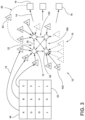
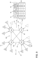
- reference numeral 10 generally refers to a peer-to-peer server network that contains a plurality of servers 12 that are adapted to place one or more live video feeds 14 in communication with one or more customer terminals 16.
- the use of the peer-to-peer server network 10 can be adapted to place the live video feed 14 in communication with the customer terminal 16 without recording portions of the live video feed 14 within the peer-to-peer server network 10.
- a live video feed balancing system 18 for delivering the plurality of live video feeds 14 to the customer terminals 16 includes a plurality of servers 12 that are placed in communication with one another to define a peer-to-peer server network 10.
- each server 12 of the peer-to-peer server network 10 is placed in communication with each of the remaining servers 42 of the peer-to-peer server network 10. In this manner, any one server 12 within the peer-to-peer server network 10 is able to communicate with each of the remaining servers 42 of the peer-to-peer server network 10. Accordingly, the peer-to-peer server network 10 contains no "master” server and no "slave” server such as is commonly found in hierarchical server networks.
- each server 12 defines a monitoring server 30 that monitors at least one corresponding performance criteria 32 of a dedicated server 34 of the peer-to-peer server network 10.
- Each monitoring server 30 can define a corresponding hosting capacity 36 for the dedicated server 34. It is contemplated that the corresponding hosting capacity 36 of the dedicated server 34 is based on the at least one corresponding performance criteria 32 evaluated by the monitoring server 30.
- Each monitoring server 30 of the peer-to-peer server network 10 communicates through an outgoing communication the corresponding hosting capacity 36 of the respective dedicated server 34 to the remaining servers 42.
- each server 12 of the peer-to-peer server network 10 defines both a monitoring server 30 and a dedicated server 34. Accordingly, the monitoring servers 30 of the peer-to-peer server network 10 are adapted to monitor only one dedicated server 34 to evaluate the at least one corresponding performance criteria 32 to arrive at a corresponding hosting capacity 36 for one respective dedicated server 34.
- the plurality of servers 12 of the peer-to-peer server network 10 cooperatively assess the communicated corresponding hosting capacities from all of the monitoring servers 30 to determine a potential hosting server 38.
- the potential hosting server 38 is defined as having a first hosting capacity 40 and the remaining servers 42 are defined as having a range of second hosting capacities 44.
- the first hosting capacity 40 is greater than any of the corresponding hosting capacities defined within the range of second hosting capacities 44.
- the plurality of servers 12 of the peer-to-peer server network 10 cooperatively assess the communicated corresponding hosting capacities to determine which respective dedicated server 34 has a greater corresponding hosting capacity 36 than that of the remaining servers 42 of the peer-to-peer server network 10.
- the potential hosting server 38 in response to a hosting request 46 for a live video feed 14 from a customer terminal 16, is placed in communication with an image capturing device 48 that delivers the requested live video feed 14.
- the potential hosting server 38 in response to the request, places the image capturing device 48 in selective communication with the potential hosting server 38 in order to deliver the live video feed 14 to the customer terminal 16.
- the potential hosting server 38 now defines an active hosting server 50 of the peer-to-peer server network 10 with respect to the requested image capturing device 52.
- the live video feed 14 can include various types of video and audio information that is captured by the image capturing device 48.
- video and audio information can include, but is not limited to, thermal imaging, closed captioning, and other video and audio information.
- the live video feed may also include certain status or identification information regarding the particular patient 84 being monitored.
- Such information may include health-related information (heart rate, blood pressure, condition specific information, and the like), age, the primary language of the patient 84, and other similar information that can be included within or embedded within the live video feed 14
- the monitoring servers 30 of the peer-to-peer server network 10 are adapted to be self-monitoring servers 60, such that the monitoring server 30 and the respective dedicated server 34 being monitored are one and the same.
- each server 12 of the peer-to-peer server network 10 is a self-monitoring server 60 that monitors its own corresponding performance criteria 32 and evaluates this corresponding performance criteria 32 to arrive at a corresponding hosting capacity 36 for the self-monitoring server 60. This information is then communicated from each self-monitoring server 60 to each of the remaining servers 42 of the peer-to-peer server network 10.
- the at least one corresponding performance criteria 32 can include, but is not limited to, utilization of the central processing unit, the utilization of the random access memory, the utilization of the network bandwidth, percentage of network utilization, percentage of memory utilization, remaining data capacity, and other similar criteria. It is also contemplated that each of these criteria can be evaluated in the positive (i.e., how much capacity is available) or in the negative (i.e., how much capacity is used).
- each of the self-monitoring servers 60 of the peer-to-peer server network 10 can balance the hosting of live video feeds 14 among each of the self-monitoring servers 60 as various hosting requests 46 are made by the various customer terminals 16 with respect to various image capturing devices 48 that deliver the various corresponding live video feeds 14.
- the peer-to-peer server network 10 can perform a self-assessment and determine which server 12 of the peer-to-peer server network 10 is best equipped to handle the new live video feed 14 from one or more image capturing devices 48.
- the peer-to-peer server network 10 can periodically perform a self-assessment to determine whether the various servers 12 of the peer-to-peer server network 10 are being utilized in an economical fashion and, if necessary, perform a balancing operation 70 with respect to the various live video feeds 14 being hosted by the servers 12 of the peer-to-peer server network 10.
- the image capturing device 48 is one of a plurality of image capturing devices 48 that are each in selective communication with the peer-to-peer server network 10. It is contemplated that each image capturing device 48 of the plurality of image capturing devices 48 is able to be hosted or placed in communication with any one server 12 within the peer-to-peer server network 10. Accordingly, hosting functions for a particular image capturing device 48 can be transferred from one server 12 to one of the remaining servers 42 where it is determined to be necessary to perform such a transfer based upon the various assessments and balancing operations 70 performed by the peer-to-peer server network 10.
- the customer terminal 16 can be one of a plurality of customer terminals 16 that are each in selective communication with the peer-to-peer server network 10.
- each customer terminal 16 is in selective communication with any one or more servers 12 of the peer-to-peer server network 10. It is contemplated that any one customer terminal 16 can be in communication with any combination of servers 12 or all of the servers 12 within the peer-to-peer server network 10, depending on the number of live video feeds 14 that are being live-streamed to the particular customer terminal 16 via the servers 12 of the peer-to-peer server network 10.
- the customer terminals 16 may be characterized as processor-driven monitors 80 that display the various live video feeds 14 of corresponding image capturing devices 48.
- a person 82 can be tasked with observing the monitor 80 having the displayed live video feeds 14. This person 82, typically, looks to see if the patient 84 is in their bed 86 in their hospital room 88. If the patient 84 attempts to get out of bed 86, when not authorized to do so, the person 82 viewing the live video feed 14 for that patient 84 can alert a medical staff 90 near the patient 84 to provide assistance.
- the image capturing devices 48 can include standard video cameras as well as motion sensors, microphones, speakers, night vision capabilities and other communications equipment to monitor the patient 84 and provide a live video feed 14 to the customer terminal 16 via the peer-to-peer server network 10.
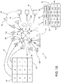
- the peer-to-peer server network 10 is adapted to provide hosting capabilities for one or more live video feeds 14 from respective image capturing devices 48. It is contemplated that the corresponding total hosting capacity 100 of each server 12 can correspond to a certain number of hosted feeds 102 that a particular server 12 is able to handle at any particular time. By way of example, and not limitation, a first server within the peer-to-peer server network 10 may be able to provide for a total hosting capacity 100 of up to three hosted feeds 102.
- a second server 106 within the peer-to-peer server network 10 may be able to provide for four hosted feeds 102, a third server 108 within the peer-to-peer server network 10 may be able to provide for five hosted feeds 102 and a fourth server 110 within the peer-to-peer server network 10 may provide for two hosted feeds 102.
- the total hosting capacity 100 of each server 12 listed herein is exemplary in nature and a server 12 of the peer-to-peer server network 10, in actuality, may be able to host large numbers of hosted feeds 102. The exact number of hosted feeds 102 can vary depending upon the configuration of the particular server 12 within the peer-to-peer server network 10.
- each server 12 within the peer-to-peer server network 10 continually, or periodically, communicates at least one of the corresponding performance criteria 32 and/or the corresponding hosting capacity 36 for the self-monitoring server 60 to the remaining servers 42 of the peer-to-peer server network 10. Accordingly, at any one time, the servers 12 of the peer-to-peer server network 10 cooperatively determine a potential hosting server 38, such that when a hosting request 46 is received from a customer terminal 16, the potential hosting server 38 is ready to act as the active hosting server 50 for the particular live video feed 14.
- various customer terminals 16 can make hosting requests 46 for a particular live video feed 14 from a corresponding image capturing device 48. Termination requests 120 may also be received for stopping a live video feed 14 for a particular image capturing device 48.
- the peer-to-peer server network 10 performs another assessment or balancing operation 70 to reevaluate the hosting capabilities of each self-monitoring server 60 to determine the potential hosting server 38 at any particular time.
- the identity of the potential hosting server 38 can change from one server 12 to another server 12 based upon the evaluation of the corresponding performance criteria 32 of the servers 12 of the peer-to-peer server network 10.
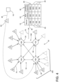
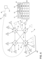
- the peer-to-peer server network 10 exemplified in FIGS. 2 and 3 show first, second, third and fourth servers 104, 106, 108, 110 of a self-monitoring type that make up the peer-to-peer server network 10.
- the exemplified peer-to-peer server network 10 shows that image capturing devices 48 (labeled A-J) are currently hosted by one of the first through fourth servers 104, 106, 108, 110, which can be of the self-monitoring variety.
- Each of these servers 12, in turn, is in communication with at least one customer terminal 16 of the plurality of customer terminals 16.
- the peer-to-peer server network 10 When a hosting request 46 from one of the customer terminals 16 for the live video feed 14 corresponding to image capturing device 48 (L) is sent to the peer-to-peer server network 10, the peer-to-peer server network 10 conducts a self-assessment or balancing operation 70 to determine the potential hosting server 38. It is contemplated that the self-assessed balancing operation 70 may have occurred before the hosting request 46 arrived such that the peer-to-peer server network 10 has already determined the potential hosting server 38. When the hosting request 46 for image capturing device 48 (L) is sent to the peer-to-peer server network 10, the peer-to-peer server network 10 determines that the third server 108 of the peer-to-peer server network 10 is the potential hosting server 38 at that time.
- This determination may be made based upon the fact that the third hosting server 108, as exemplified in image, has the greatest corresponding hosting capacity 36 of the first through fourth self-monitoring servers 104, 106, 108, 110. This can be expressed as the corresponding hosting capacity 36 in relation to the total hosting capacity 100 for each server 12.
- the third server 108 is then placed in communication with both the image capturing device 48 (L) as well as the customer terminal 16 that sent the hosting request 46 with respect to image capturing device 48 (L). In this manner, the third server 108 of the peer-to-peer server network 10 has become the active hosting server 50 with respect to image capturing device 48 (L).
- the peer-to-peer server network 10 may perform another self-assessed balancing operation 70 to redefine which server 12 of the peer-to-peer server network 10 is the potential hosting server 38 in the event of another hosting request 46.
- a particular server 12 may be left with a corresponding hosting capacity 36 that is far greater or less than the remaining servers 12 of the peer-to-peer server network 10.
- a periodic self-assessed balancing operation 70 of the peer-to-peer server network 10 may result in a rebalancing of the hosted feeds 102 of the servers 12 of the peer-to-peer server network 10.
- One of the servers 12 that is particularly loaded with hosted feeds 102 may have one of those hosted feeds 102 transferred to a server 12 having a much higher corresponding hosting capacity 36.
- This balancing function can help to ensure that the various servers 12 of the peer-to-peer server network 10 are not overtaxed relative to the remaining servers 12 of the peer-to-peer server network 10.
- the transition of hosted feeds 102 from one server 12 to one of the remaining servers 12 can be performed by the peer-to-peer server network 10 itself.
- the various servers 12 of the peer-to-peer server network 10 can act as a cooperative processor 130 that initiates each balancing operation 70, receives each hosting request 46 and termination request 120, and performs various computing operations during performance of the peer-to-peer server network 10.
- the various self-monitoring servers 60 of the peer-to-peer server network 10 are not necessarily located in a single physical location. It is contemplated that the various servers 12 can be positioned in two or more different and/or separate geographic locations, where the various servers 12 are placed in communication via various network connections, cloud computing connections, and other similar data connections. Additionally, it is contemplated that each server 12 of the peer-to-peer server network 10 can be limited to only hosting the various live video feeds 14 from the respective image capturing devices 48.
- no recording or buffering of the live video feeds 14 is conducting by the servers 12, and each server 12 acts as a conduit or gated passage through which the image capturing device 48 can be placed in communication with one or more customer terminals 16. It is also contemplated that recording and/or "buffering" functions may be performed at the customer terminal 16. It is also contemplated that buffering and/or recording may be conducted by one or more servers 12 of a peer-to-peer server network 10. Such buffering and recording functions can be stored directly on the self-monitoring server 60 acting as the active hosting server 50 in communication with the corresponding image capturing device 48. It is also contemplated that a separate data recording device in communication with the peer-to-peer server network 10 can be utilized for buffering and/or recording functions.
- the buffered and/or recorded data can be available to any one or more of the customer terminals 16.
- the buffered and/or recorded data can be transferred to a different self-monitoring server 60 in response to a change in hosting designations as a result of a balancing operation 70..
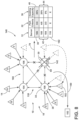
- a failure mode 140 of the peer-to-peer server network 10 can be defined by the absence of a communication from any one or more of the servers 12 to the remaining servers 12 in response to the performance of the balancing operation 70. Where no communication is received by the remaining servers 12, a complete performance of the balancing operation 70 of all of the servers 12 of the peer-to-peer server network 10 is not possible.
- the remaining servers 12 of the peer-to-peer server network 10 may initiate a failure mode 140 response to reallocate the hosted feeds 102 that are currently being hosted by the server 12 that is experiencing the failure mode 140 or the off-line server 142.
- the remaining servers 12 perform a balancing operation 70 without including the off-line server 142.
- the remaining servers 12 determine a potential hosting server 38 with respect to the remaining servers 12 by evaluating the corresponding hosting capacity 36 of the remaining servers 12.
- a hosted feed 102 from the off-line server 142 is then automatically transferred to the potential hosting server 38 to define an active hosting server 50 with respect to the reallocated hosted feed 102.
- a failure signal 150 may be sent to a service module 152 or service provider such that maintenance can be performed on the off-line server 142 and the peer-to-peer server network 10.
- This failure mode 140 is initiated in order to minimize the amount of downtime of hosted live video feeds 14 experienced by the customer terminals 16 in the event of a failure within the peer-to-peer server network 10.
- a failure at one of the servers 12 of a hierarchical server network can necessitate the manual transfer of video feeds 14 from a failed server 12 to an on-line server. This operation can take a substantial amount of time. This time can be critical where a particular patient 84 requires around-the-clock monitoring.
- certain live video feeds 14 from various image capturing devices 48 can be assigned a priority level.
- a high priority can be placed upon an image capturing device 48 that is used to monitor a patient 84 that may require high levels of monitoring.
- Lower priority image capturing devices 48 may be assigned for health care patients 84 requiring less monitoring or are of a lower risk when not being monitored.
- the higher priority image capturing devices 48 may be transferred from the off-line server 142 to the new potential hosting server 38 among the remaining servers 12, before the lower priority image capturing devices 48.
- the amount of downtime for each of the image capturing devices 48 can be kept to a minimum for high-priority image capturing devices 48. While not significantly longer in time, a lesser priority image capturing device 48 may be transferred after higher priority image capturing devices 48. It is contemplated that the priority level assigned to each image capturing device 48 may be assessed by the health care professional monitoring the particular patient 84. A history of incidents for a particular patient 84 can also factor into the assessment of a particular priority level for a respective video monitoring device.
- a patient 84 that frequently tries to get out of bed 86 when instructed to remain in bed 86 may require a higher priority level than a patient 84 that has fewer or no incidents of attempting to get out of bed 86 when instructed not to do so.
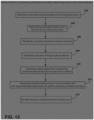
- a method 400 for live streaming a plurality of server-hosted live video feeds 14 using a peer-to-peer server network 10.
- a plurality of potential customer terminals 16 are identified by a peer-to-peer server network 10 (step 402).
- the potential customer terminals 16 can be represented by a paid service or fee-based service that is required in order to utilize the peer-to-peer server network 10.
- each of these potential customer terminals 16 are placed in selective communication with one or more servers 12 of the peer-to-peer server network 10.
- the identification of a particular customer terminal 16 can occur at various times in the operation of the peer-to-peer server network 10. It is contemplated that the identification step 402 can occur in response to a hosting request 46, activating a subscription service involving the peer-to-peer server network 10, connection with at least one server 12 of the peer-to-peer server network 10, combinations thereof, and other similar events that may occur during operation of the peer-to-peer server network 10.
- a plurality of image capturing devices 48 are also identified by the peer-to-peer server network 10 (step 404).
- the various image capturing devices 48 can be owned or operated by various health care providers such as hospitals, medical facilities, nursing homes, hospice providers, and other similar health care providers.
- the plurality of servers 12 are coupled to define the peer-to-peer server network 10 (step 406). Again, each server 12 of the peer-to-peer server network 10 is in communication with each remaining server 12 of the peer-to-peer server network 10. A corresponding hosting capacity 36 is determined for each server 12 of the plurality of servers 12 within the peer-to-peer server network 10 (step 408). Each server 12 within the peer-to-peer server network 10 defines a monitoring server 30 that operates to monitor at least one performance criteria 32 of one corresponding monitored or dedicated server 34 within the peer-to-peer server network 10. Accordingly, each monitoring server 30 assigns a corresponding hosting capacity 36 for the corresponding dedicated server 34 based upon the at least one performance criteria 32.
- the corresponding hosting capacity 36 for each corresponding dedicated server 34 of the peer-to-peer server network 10 is then communicated to each remaining server 12 of the peer-to-peer server network 10.
- this step 408 of determining a hosting capacity 36 can then be performed continuously, periodically, in response to a hosting request 46 or termination request 120, in response to a failure mode 140 indication, combinations thereof, or other periodic times as dictated by the peer-to-peer server network 10.
- a video hosting request 46 is delivered from a requesting customer terminal 16 of the plurality of potential customer terminals 16 to the peer-to-peer server network 10 (step 410).
- the hosting request 46 identifies a requested image capturing device 52 of the plurality of image capturing devices 48 that is to be placed in communication with the requesting customer terminal 16 via a potential hosting server 38 of the peer-to-peer server network 10.
- the potential hosting server 38 is then identified with respect to the hosting request 46 (step 412). It is contemplated that the hosting server or potential hosting server 38 is defined as the server 12 having a corresponding first hosting capacity 40 as opposed to the remaining servers 12 which are defined as having a range of corresponding second hosting capacities 44.
- the corresponding first hosting capacity 40 is greater than any of the corresponding hosting capacities within the range of corresponding second hosting capacities 44.
- the requested image capturing device 52 is then placed in communication with the potential hosting server 38 and the potential hosting server 38 is placed in communication with the requesting customer terminal 16 to deliver a live video feed 14 from the requested image capturing device 52 to the requested customer terminal 16 (step 414).
- the potential hosting server 38 is then defined as the active hosting server 50 with respect to the particular image capturing device 48.
- a method 500 for live streaming a plurality of server-hosted live video feeds 14 using a peer-to-peer server network 10 is also disclosed.
- a server web 160 in the form of a peer-to-peer server network 10 is defined by a plurality of servers 12, typically, self-monitoring servers 60, of the peer-to-peer server network 10 (step 502).
- each server 12 of the server web 160 is in communication with each remaining server 12 of the server web 160 and each server 12 monitors at least one corresponding performance criteria 32 of the respective dedicated server 34. It is also contemplated that each server 12 communicates the corresponding performance criteria 32 to each remaining server 12 of the server web 160.
- the server web 160 can correspond to the peer-to-peer server network 10 disclosed herein.
- a potential hosting server 38 is determined by the server web 160 (step 504).
- the servers 12 of the server web 160 assess each corresponding performance criteria 32 to define a first performance criteria 32 that corresponds to the potential hosting server 38.
- Each remaining performance criteria 32 of the remaining servers 12 collectively defines a range of second performance criteria 32.
- this self-assessment, or balancing operation 70 by the server web 160 identifies the potential hosting server 38 as the server 12 having the greatest corresponding hosting capacity 36 for handling a subsequent or previously received hosting request 46.
- at least one or a plurality of potential customer terminals 16 are identified (step 506).
- At least one or a plurality of image capturing devices 48 are also identified (step 508).
- a video hosting request 46 is delivered from a requesting customer terminal 16 of the plurality of customer terminals 16 to the peer-to-peer server network 10 (step 510). It is contemplated that the video hosting request 46 identifies a requested image capturing device 52 or a plurality of requested image capturing devices 52 to be placed in communication with the requested customer terminal 16 via the potential hosting server 38 of the peer-to-peer server network 10. The potential hosting server 38 is then placed in communication with the requested image capturing device 52 and the requested customer terminal 16 (step 512). In this manner, the potential hosting server 38 then defines an active hosting server 50 that defines communication between the requested image capturing device 52 and the requested customer terminal 16.
- An updated potential hosting server 38 is then redetermined by the peer-to-peer server network 10 (step 514).
- the active hosting server 50 and the remaining self-monitoring servers 60 of the server web 160 communicate update corresponding performance criteria 32 to each other self-monitoring server 60 of the server web 160 to redefine an updated corresponding first criteria and an updated range of corresponding second performance criteria 32.
- the identity of the potential hosting server 38 may change to a different server 12 within the server web 160.
- a video termination request 120 can be received from the requesting customer terminal 16 that is in communication with the requested image capturing device 52 via the active hosting server 50 (step 516). It is contemplated that the termination request 120 relates to selectively terminating communication between the requesting customer terminal 16 and the requested image capturing device 52.
- the live video feed 14 is stopped, interrupted, or otherwise terminated (step 518).
- the corresponding performance criteria 32 for each self-monitoring server 60 in the server web 160 is then redetermined after termination of the live video feed 14 (step 520).
- the updated potential hosting server 38 is then re-identified (step 522).
- the previously active hosting server 50 and the remaining self-monitoring servers 60 communicate updated corresponding performance criteria 32 to each other self-monitoring server 60 of the server web 160 to redefine an updated first corresponding performance criteria 32 and an updated second range of corresponding performance criteria 32.
- the identity of the potential hosting server 38 may change after performance of the termination request 120 from the requesting customer terminal 16.
- a method 600 for operating a peer-to-peer server network 10 in the event of a failure mode 140 of the peer-to-peer server network 10.
- a server web 160 having a plurality of self-monitoring servers 60 is defined (step 602).
- one of the self-monitoring servers 60 may define a failure mode 140.
- one of the self-monitoring servers 60 may be identified as an off-line server 142 of the server web 160 (step 604).
- an off-line server 142 may be defined as a self-monitoring server 60 that fails to transmit a communication regarding at least one of the corresponding performance criteria 32 or the corresponding hosting capacity 36 to the remaining servers 42 of the server web 160.
- Other indications that a self-monitoring server 60 or other type of server 12 is defining an off-line server 142 can include, but are not limited to, a power failure, physical damage to the off-line server 142, other communications failure involving the off-line server 142, combinations thereof, and other similar events indicative of a self-monitoring server 60 or other type of server 12 of the server web 160 not functioning properly.
- the hosted feeds 102 of the off-line server 142 are then identified (step 606).
- the potential hosting server 38 among the remaining servers 42, that are free of or do not define the failure mode 140, of the server web 160 is then identified to take over the hosting functions with respect to the hosted feed 102 of the off-line server 142 (step 608).
- the hosted feed 102 of the off-line server 142 is transferred to the potential hosting server 38 that now defines the active hosting server 50 as to the transferred hosted feed 102 (step 610).
- the balancing operation 70 can then be performed again to redetermine the potential hosting server 38 with respect to the next hosted feed 102 to be transferred from the off-line server 142, if any. While all of the hosted feeds 102 are being transferred away from the off-line server 142, the off-line server 142 can be repaired. Once repaired, the newly repaired self-monitoring server 60 is reinserted into the server web 160 and the balancing operation 70 is again conducted to apportion the various hosted feeds 102 of the server web 160 among the self-monitoring servers 60 of the server web 160 (step 612).
- peer-to-peer server network 10 it is contemplated that during the course of performance of a particular peer-to-peer server network 10, additional servers 12 can be added to the peer-to-peer server network 10.
- a self-assessed balancing operation 70 of the peer-to-peer server network 10 is performed to balance the hosted feeds 102 of the peer-to-peer server network 10 among the various servers 12 of the peer-to-peer server network 10.
- the use of the peer-to-peer server network 10 is adapted to serve a large number of image capturing devices 48 having a number that exceeds or potentially greatly exceeds the number of servers 12 in the peer-to-peer server network 10.
- the number of customer terminals 16 of the plurality of customer terminals 16 can exceed or can also greatly exceed the number of servers 12 in the peer-to-peer server network 10.
- the use of the peer-to-peer server network 10 serves to provide a balanced hosting system through which downtime can be minimized as a result of failure, overloading or maintenance of the various servers 12 within the peer-to-peer server network 10.
- the apparatus and methods described herein are adapted to automatically transfer hosted feeds 102 from one server 12 to another in response to various inputs and events that are experienced by the peer-to-peer server network 10. Minimizing the downtime in the posted feeds delivered by the peer-to-peer server network 10 can maintain a consistent surveillance regimen of health care patients 84, and also health care providers that can decrease the incidents of patients 84 being injured when attempting to get out of bed 86 when not instructed to do so.
- the use of the peer-to-peer server network 10 can also allow for a single customer terminal 16 to monitor multiple live video feeds 14, thereby decreasing the amount of manpower necessary to monitor healthcare patients 84.
Applications Claiming Priority (3)
| Application Number | Priority Date | Filing Date | Title |
|---|---|---|---|
| US15/241,355 US10057337B2 (en) | 2016-08-19 | 2016-08-19 | Video load balancing system for a peer-to-peer server network |
| PCT/US2017/038530 WO2018034732A1 (en) | 2016-08-19 | 2017-06-21 | Video load balancing system for a peer-to-peer server network |
| EP17841793.7A EP3501172B1 (en) | 2016-08-19 | 2017-06-21 | Video load balancing system for a peer-to-peer server network |
Related Parent Applications (1)
| Application Number | Title | Priority Date | Filing Date |
|---|---|---|---|
| EP17841793.7A Division EP3501172B1 (en) | 2016-08-19 | 2017-06-21 | Video load balancing system for a peer-to-peer server network |
Publications (1)
| Publication Number | Publication Date |
|---|---|
| EP4156652A1 true EP4156652A1 (en) | 2023-03-29 |
Family
ID=61192389
Family Applications (2)
| Application Number | Title | Priority Date | Filing Date |
|---|---|---|---|
| EP22197710.1A Pending EP4156652A1 (en) | 2016-08-19 | 2017-06-21 | Video load balancing system for a peer-to-peer server network |
| EP17841793.7A Active EP3501172B1 (en) | 2016-08-19 | 2017-06-21 | Video load balancing system for a peer-to-peer server network |
Family Applications After (1)
| Application Number | Title | Priority Date | Filing Date |
|---|---|---|---|
| EP17841793.7A Active EP3501172B1 (en) | 2016-08-19 | 2017-06-21 | Video load balancing system for a peer-to-peer server network |
Country Status (23)
| Country | Link |
|---|---|
| US (1) | US10057337B2 (es) |
| EP (2) | EP4156652A1 (es) |
| JP (2) | JP7026103B2 (es) |
| KR (1) | KR102319144B1 (es) |
| CN (2) | CN109644287A (es) |
| AU (2) | AU2017312441B2 (es) |
| BR (1) | BR112019003316A2 (es) |
| CA (1) | CA3034031C (es) |
| CL (1) | CL2019000328A1 (es) |
| CO (1) | CO2019002122A2 (es) |
| CR (1) | CR20190083A (es) |
| EA (1) | EA201990515A1 (es) |
| EC (1) | ECSP19011553A (es) |
| IL (1) | IL264869B (es) |
| JO (1) | JOP20190021A1 (es) |
| MX (1) | MX2019001969A (es) |
| MY (1) | MY202472A (es) |
| NI (1) | NI201900015A (es) |
| PE (1) | PE20190499A1 (es) |
| PH (1) | PH12019500307A1 (es) |
| SG (1) | SG11201900982WA (es) |
| SV (1) | SV2019005834A (es) |
| WO (1) | WO2018034732A1 (es) |
Families Citing this family (6)
| Publication number | Priority date | Publication date | Assignee | Title |
|---|---|---|---|---|
| EP3504874A1 (en) * | 2016-08-23 | 2019-07-03 | Koninklijke Philips N.V. | Hospital video surveillance system |
| CN107872643A (zh) * | 2016-09-23 | 2018-04-03 | 伊姆西Ip控股有限责任公司 | 用于视频监控系统的故障恢复方法和装置 |
| CN110069210B (zh) * | 2018-01-23 | 2021-09-28 | 杭州海康威视系统技术有限公司 | 一种存储系统、存储资源的分配方法及装置 |
| JP7123164B2 (ja) * | 2018-11-28 | 2022-08-22 | オリンパス株式会社 | 医療画像記録制御装置、医療画像記録制御システム及び医療画像記録制御方法 |
| US11394695B2 (en) * | 2020-07-02 | 2022-07-19 | Kpn Innovations, Llc. | Methods and systems for generating a secure communication channel interface for video streaming of sensitive content |
| US11837363B2 (en) | 2020-11-04 | 2023-12-05 | Hill-Rom Services, Inc. | Remote management of patient environment |
Citations (1)
| Publication number | Priority date | Publication date | Assignee | Title |
|---|---|---|---|---|
| US20100250678A1 (en) * | 2006-11-10 | 2010-09-30 | Microsoft Corporation | Peer-to-peer aided live video sharing system |
Family Cites Families (48)
| Publication number | Priority date | Publication date | Assignee | Title |
|---|---|---|---|---|
| CA2415770C (en) * | 2000-07-17 | 2010-04-27 | Galactic Computing Corporation | Method and system for providing dynamic hosted service management |
| US7941482B2 (en) | 2003-06-04 | 2011-05-10 | Sony Computer Entertainment Inc. | System and method for managing performance between multiple peers in a peer-to-peer environment |
| JP4331203B2 (ja) | 2003-06-04 | 2009-09-16 | 株式会社ソニー・コンピュータエンタテインメント | ピアツーピアネットワークのためのコンテンツ分散型オーバーレイネットワーク |
| US9525566B2 (en) * | 2003-07-31 | 2016-12-20 | Cloudsoft Corporation Limited | Self-managed mediated information flow |
| US9910341B2 (en) * | 2005-01-31 | 2018-03-06 | The Invention Science Fund I, Llc | Shared image device designation |
| JP2006260059A (ja) | 2005-03-16 | 2006-09-28 | Hitachi Information Technology Co Ltd | サーバ装置 |
| US20070204078A1 (en) * | 2006-02-09 | 2007-08-30 | Intertrust Technologies Corporation | Digital rights management engine systems and methods |
| US8477658B2 (en) | 2006-04-25 | 2013-07-02 | The Hong Kong University Of Science And Technology | Intelligent peer-to-peer media streaming |
| US9907473B2 (en) * | 2015-04-03 | 2018-03-06 | Koninklijke Philips N.V. | Personal monitoring system |
| US9325786B2 (en) | 2006-07-27 | 2016-04-26 | The Hong Kong University Of Science And Technology | Peer-to-peer interactive media-on-demand |
| CN101068155B (zh) | 2006-09-20 | 2010-06-09 | 腾讯科技(深圳)有限公司 | 一种对等连接流媒体直播系统及其采集服务器 |
| WO2008064356A1 (en) * | 2006-11-22 | 2008-05-29 | Metis Enterprise Technologies Llc | Real-time multicast peer-to-peer video streaming platform |
| DE602006004073D1 (es) | 2006-11-23 | 2009-01-15 | Ntt Docomo Inc | |
| GB2444995B (en) | 2006-12-21 | 2011-07-27 | Vodafone Plc | Peer to peer network |
| CN101018201A (zh) | 2007-01-17 | 2007-08-15 | 黄从来 | 一种p2p流媒体直播技术的平行扩展方法 |
| US9172918B2 (en) * | 2007-02-02 | 2015-10-27 | Honeywell International Inc. | Systems and methods for managing live video data |
| US8832290B2 (en) * | 2007-02-23 | 2014-09-09 | Microsoft Corporation | Smart pre-fetching for peer assisted on-demand media |
| CN101207550B (zh) * | 2007-03-16 | 2010-09-15 | 中国科学技术大学 | 负载均衡系统及多种业务实现负载均衡的方法 |
| CN101282281B (zh) * | 2007-04-03 | 2011-03-30 | 华为技术有限公司 | 一种媒体分发系统、装置及流媒体播放方法 |
| US8316146B2 (en) | 2007-07-13 | 2012-11-20 | Spotify Ab | Peer-to-peer streaming of media content |
| US9769255B2 (en) | 2007-12-24 | 2017-09-19 | Core Wireless Licensing S.A.R.L. | Continuous scheduling for peer-to-peer streaming |
| US9063993B2 (en) * | 2008-01-31 | 2015-06-23 | Microsoft Technology Licensing, Llc | Coexistence tools for synchronizing properties between on-premises customer locations and remote hosting services |
| EA017014B1 (ru) * | 2008-02-22 | 2012-09-28 | Сейдж Коннекс, Ллк | Персональный портал данных в коммутируемой телефонной сети общего пользования и онлайн-дом с виртуальными комнатами и объектами |
| CN102047640B (zh) | 2008-05-28 | 2016-04-13 | 汤姆逊许可证公司 | 多个头的分层级集群化的对等现场流式传输系统 |
| US8650301B2 (en) | 2008-10-02 | 2014-02-11 | Ray-V Technologies, Ltd. | Adaptive data rate streaming in a peer-to-peer network delivering video content |
| US7996546B2 (en) | 2008-10-02 | 2011-08-09 | Ray-V Technologies, Ltd. | Dynamic allocation of a quota of consumer nodes connecting to a resource node of a peer-to-peer network |
| US9235448B2 (en) | 2008-11-25 | 2016-01-12 | Citrix Systems, Inc. | Systems and methods for batchable hierarchical configuration |
| WO2011109788A1 (en) * | 2010-03-05 | 2011-09-09 | Veetle, Inc. | Pod-based server backend infrastructure for peer-assisted applications |
| US20130086278A1 (en) | 2010-06-17 | 2013-04-04 | Nokia Siemens Networks Oy | Peer-to-peer system |
| TWI415427B (zh) | 2010-11-04 | 2013-11-11 | Ind Tech Res Inst | 同儕即時串流系統與方法 |
| JP5529177B2 (ja) | 2011-01-19 | 2014-06-25 | ネイバー ビジネス プラットフォーム コーポレーション | P2p基盤のストリーミングサービスでバッファリングを行うシステムおよび方法、並びにクライアントでバッファリングを処理するアプリケーションを配布するシステム |
| US8909747B2 (en) | 2011-02-24 | 2014-12-09 | Alcatel Lucent | Method and apparatus for localization in peer-to-peer systems |
| CA2828489C (en) | 2011-02-28 | 2019-09-24 | Bittorrent, Inc. | Sharing content according to a protocol for peer-to-peer live streaming |
| CN102215163B (zh) * | 2011-03-24 | 2014-04-09 | 东莞中山大学研究院 | 一种多服务器视频点播处理方法 |
| CN102740165B (zh) * | 2011-04-01 | 2015-07-15 | 中国电信股份有限公司 | 对等流媒体直播系统及其中的数据传输方法 |
| CN102231761A (zh) * | 2011-08-12 | 2011-11-02 | 乐视网信息技术(北京)股份有限公司 | 一种p2p数据交互方法 |
| US9137258B2 (en) * | 2012-02-01 | 2015-09-15 | Brightpoint Security, Inc. | Techniques for sharing network security event information |
| US10547693B2 (en) * | 2012-09-07 | 2020-01-28 | Avigilon Corporation | Security device capability discovery and device selection |
| US9680926B2 (en) * | 2012-12-19 | 2017-06-13 | Hive Streaming Ab | Nearest peer download request policy in a live streaming P2P network |
| US9444863B2 (en) * | 2013-06-06 | 2016-09-13 | Intel Corporation | Manager for DASH media streaming |
| CN103354545B (zh) | 2013-06-24 | 2015-04-15 | 西安交通大学 | 一种基于云计算的p2p流媒体服务器集群部署方法 |
| US10142381B2 (en) * | 2014-07-22 | 2018-11-27 | Intellivision Technologies Corp. | System and method for scalable cloud services |
| US9998354B2 (en) * | 2013-09-24 | 2018-06-12 | Netflix, Inc. | Server selection for content distribution |
| US9349256B2 (en) * | 2013-09-24 | 2016-05-24 | Otho Dale Hill | System and method for providing remote gaming featuring live gaming data |
| US8769610B1 (en) * | 2013-10-31 | 2014-07-01 | Eventure Interactive, Inc. | Distance-modified security and content sharing |
| US9538134B2 (en) | 2013-12-23 | 2017-01-03 | Vonage Business Inc. | Method and system for resource load balancing in a conferencing session |
| US20150297121A1 (en) | 2014-04-16 | 2015-10-22 | AvaSure Holdings, Inc. | Patient Monitoring System and Apparatus |
| CN104320627B (zh) * | 2014-11-10 | 2017-12-12 | 武汉市中心医院 | 一种医院病房视频监视的方法以及相关应用服务系统 |
-
2016
- 2016-08-19 US US15/241,355 patent/US10057337B2/en active Active
-
2017
- 2017-06-16 JO JOP/2019/0021A patent/JOP20190021A1/ar unknown
- 2017-06-21 BR BR112019003316A patent/BR112019003316A2/pt unknown
- 2017-06-21 MX MX2019001969A patent/MX2019001969A/es unknown
- 2017-06-21 JP JP2019506485A patent/JP7026103B2/ja active Active
- 2017-06-21 EP EP22197710.1A patent/EP4156652A1/en active Pending
- 2017-06-21 EA EA201990515A patent/EA201990515A1/ru unknown
- 2017-06-21 CN CN201780050818.6A patent/CN109644287A/zh active Pending
- 2017-06-21 CN CN202110192448.8A patent/CN112929377B/zh active Active
- 2017-06-21 PE PE2019000360A patent/PE20190499A1/es unknown
- 2017-06-21 CR CR20190083A patent/CR20190083A/es unknown
- 2017-06-21 WO PCT/US2017/038530 patent/WO2018034732A1/en unknown
- 2017-06-21 CA CA3034031A patent/CA3034031C/en active Active
- 2017-06-21 KR KR1020197007609A patent/KR102319144B1/ko active IP Right Grant
- 2017-06-21 AU AU2017312441A patent/AU2017312441B2/en active Active
- 2017-06-21 EP EP17841793.7A patent/EP3501172B1/en active Active
- 2017-06-21 MY MYPI2019000615A patent/MY202472A/en unknown
- 2017-06-21 SG SG11201900982WA patent/SG11201900982WA/en unknown
-
2019
- 2019-02-08 CL CL2019000328A patent/CL2019000328A1/es unknown
- 2019-02-13 PH PH12019500307A patent/PH12019500307A1/en unknown
- 2019-02-15 SV SV2019005834A patent/SV2019005834A/es unknown
- 2019-02-15 NI NI201900015A patent/NI201900015A/es unknown
- 2019-02-15 EC ECSENADI201911553A patent/ECSP19011553A/es unknown
- 2019-02-17 IL IL264869A patent/IL264869B/en active IP Right Grant
- 2019-03-06 CO CONC2019/0002122A patent/CO2019002122A2/es unknown
-
2021
- 2021-06-14 JP JP2021098397A patent/JP7332653B2/ja active Active
- 2021-11-10 AU AU2021266267A patent/AU2021266267B2/en active Active
Patent Citations (1)
| Publication number | Priority date | Publication date | Assignee | Title |
|---|---|---|---|---|
| US20100250678A1 (en) * | 2006-11-10 | 2010-09-30 | Microsoft Corporation | Peer-to-peer aided live video sharing system |
Also Published As
Similar Documents
| Publication | Publication Date | Title |
|---|---|---|
| CA3034031C (en) | Video load balancing system for a peer-to-peer server network | |
| CN112231075B (zh) | 一种基于云服务的服务器集群负载均衡控制方法及系统 | |
| RU2013140303A (ru) | Система дистанционного мониторинга для медицинских устройств через беспроводные системы связи | |
| US20150150086A1 (en) | Intelligent self-load balancing with weighted paths | |
| TW201003383A (en) | System for monitoring and diagnosing remote devices | |
| JP2000059465A (ja) | 障害監視管理方式 | |
| CN111090518A (zh) | 边缘计算设备控制方法、装置及存储介质 | |
| CN112866394B (zh) | 一种负载均衡方法、装置、系统、计算机设备和存储介质 | |
| JP2006195554A (ja) | 統合監視システム | |
| CN116453654B (zh) | 一种用于内分泌患者的数字营养管理方法和系统 | |
| JP5271737B2 (ja) | データ収集システム,及び伝送制御装置 | |
| US20210367811A1 (en) | Gateway device, communication system, and automated warehouse system | |
| JP6073211B2 (ja) | サーバ監視方法およびサーバ監視システム | |
| US20210352164A1 (en) | Data transmission protocol | |
| JP2022523263A (ja) | 医療機器位置特定および追跡システム | |
| CN111066089A (zh) | 用于在医疗保健环境中传输健康数据的系统和方法 | |
| US20120072545A1 (en) | Remote maintenance and monitoring service framework for heterogeneous device and system | |
| JP2003208218A (ja) | 監視制御システム | |
| US10658079B1 (en) | Crowd-based recommendations of a version of firmware for medical devices | |
| US10600512B1 (en) | Network-based calculation of prevalence of repeated medical imaging | |
| US20210050100A1 (en) | Reducing unnecessary scheduled preventative maintenance for medical devices | |
| WO2019082864A1 (ja) | 映像配信システム、映像配信方法、及び、映像配信プログラムを格納する記録媒体 | |
| JP2002150451A (ja) | 監視システム | |
| JP2019016272A (ja) | 管理システムおよび画像形成装置 | |
| JP2014225121A (ja) | 施設管制システム及び施設管制方法 |
Legal Events
| Date | Code | Title | Description |
|---|---|---|---|
| PUAI | Public reference made under article 153(3) epc to a published international application that has entered the european phase |
Free format text: ORIGINAL CODE: 0009012 |
|
| STAA | Information on the status of an ep patent application or granted ep patent |
Free format text: STATUS: THE APPLICATION HAS BEEN PUBLISHED |
|
| AC | Divisional application: reference to earlier application |
Ref document number: 3501172 Country of ref document: EP Kind code of ref document: P |
|
| AK | Designated contracting states |
Kind code of ref document: A1 Designated state(s): AL AT BE BG CH CY CZ DE DK EE ES FI FR GB GR HR HU IE IS IT LI LT LU LV MC MK MT NL NO PL PT RO RS SE SI SK SM TR |
|
| STAA | Information on the status of an ep patent application or granted ep patent |
Free format text: STATUS: REQUEST FOR EXAMINATION WAS MADE |
|
| 17P | Request for examination filed |
Effective date: 20230920 |
|
| RBV | Designated contracting states (corrected) |
Designated state(s): AL AT BE BG CH CY CZ DE DK EE ES FI FR GB GR HR HU IE IS IT LI LT LU LV MC MK MT NL NO PL PT RO RS SE SI SK SM TR |
|
| GRAP | Despatch of communication of intention to grant a patent |
Free format text: ORIGINAL CODE: EPIDOSNIGR1 |
|
| STAA | Information on the status of an ep patent application or granted ep patent |
Free format text: STATUS: GRANT OF PATENT IS INTENDED |
|
| INTG | Intention to grant announced |
Effective date: 20231219 |
|
| GRAS | Grant fee paid |
Free format text: ORIGINAL CODE: EPIDOSNIGR3 |
|
| GRAA | (expected) grant |
Free format text: ORIGINAL CODE: 0009210 |
|
| STAA | Information on the status of an ep patent application or granted ep patent |
Free format text: STATUS: THE PATENT HAS BEEN GRANTED |