EP4156458B1 - Nacelle de charge sans fil et support de nacelle de charge pour dispositifs de jeu à batteries rechargeables - Google Patents
Nacelle de charge sans fil et support de nacelle de charge pour dispositifs de jeu à batteries rechargeables Download PDFInfo
- Publication number
- EP4156458B1 EP4156458B1 EP22207473.4A EP22207473A EP4156458B1 EP 4156458 B1 EP4156458 B1 EP 4156458B1 EP 22207473 A EP22207473 A EP 22207473A EP 4156458 B1 EP4156458 B1 EP 4156458B1
- Authority
- EP
- European Patent Office
- Prior art keywords
- wireless charging
- game device
- pod
- charging pod
- receptacle
- Prior art date
- Legal status (The legal status is an assumption and is not a legal conclusion. Google has not performed a legal analysis and makes no representation as to the accuracy of the status listed.)
- Active
Links
Images


Classifications
-
- H—ELECTRICITY
- H01—ELECTRIC ELEMENTS
- H01F—MAGNETS; INDUCTANCES; TRANSFORMERS; SELECTION OF MATERIALS FOR THEIR MAGNETIC PROPERTIES
- H01F38/00—Adaptations of transformers or inductances for specific applications or functions
- H01F38/14—Inductive couplings
-
- H—ELECTRICITY
- H02—GENERATION; CONVERSION OR DISTRIBUTION OF ELECTRIC POWER
- H02J—ELECTRIC POWER NETWORKS; CIRCUIT ARRANGEMENTS OR SYSTEMS FOR SUPPLYING OR DISTRIBUTING ELECTRIC POWER; SYSTEMS FOR STORING ELECTRIC ENERGY
- H02J50/00—Circuit arrangements or systems for wireless supply or distribution of electric power
- H02J50/10—Circuit arrangements or systems for wireless supply or distribution of electric power using inductive coupling
-
- H—ELECTRICITY
- H02—GENERATION; CONVERSION OR DISTRIBUTION OF ELECTRIC POWER
- H02J—ELECTRIC POWER NETWORKS; CIRCUIT ARRANGEMENTS OR SYSTEMS FOR SUPPLYING OR DISTRIBUTING ELECTRIC POWER; SYSTEMS FOR STORING ELECTRIC ENERGY
- H02J50/00—Circuit arrangements or systems for wireless supply or distribution of electric power
- H02J50/40—Circuit arrangements or systems for wireless supply or distribution of electric power using two or more transmitting or receiving devices
- H02J50/402—Circuit arrangements or systems for wireless supply or distribution of electric power using two or more transmitting or receiving devices the two or more transmitting or the two or more receiving devices being integrated in the same unit, e.g. power mats with several coils or antennas with several sub-antennas
-
- H—ELECTRICITY
- H02—GENERATION; CONVERSION OR DISTRIBUTION OF ELECTRIC POWER
- H02J—ELECTRIC POWER NETWORKS; CIRCUIT ARRANGEMENTS OR SYSTEMS FOR SUPPLYING OR DISTRIBUTING ELECTRIC POWER; SYSTEMS FOR STORING ELECTRIC ENERGY
- H02J50/00—Circuit arrangements or systems for wireless supply or distribution of electric power
- H02J50/80—Circuit arrangements or systems for wireless supply or distribution of electric power involving the exchange of data, concerning supply or distribution of electric power, between transmitting devices and receiving devices
-
- H—ELECTRICITY
- H02—GENERATION; CONVERSION OR DISTRIBUTION OF ELECTRIC POWER
- H02J—ELECTRIC POWER NETWORKS; CIRCUIT ARRANGEMENTS OR SYSTEMS FOR SUPPLYING OR DISTRIBUTING ELECTRIC POWER; SYSTEMS FOR STORING ELECTRIC ENERGY
- H02J50/00—Circuit arrangements or systems for wireless supply or distribution of electric power
- H02J50/90—Circuit arrangements or systems for wireless supply or distribution of electric power involving detection or optimisation of position, e.g. alignment
-
- H—ELECTRICITY
- H02—GENERATION; CONVERSION OR DISTRIBUTION OF ELECTRIC POWER
- H02J—ELECTRIC POWER NETWORKS; CIRCUIT ARRANGEMENTS OR SYSTEMS FOR SUPPLYING OR DISTRIBUTING ELECTRIC POWER; SYSTEMS FOR STORING ELECTRIC ENERGY
- H02J7/00—Circuit arrangements for charging or discharging batteries or for supplying loads from batteries
- H02J7/02—Circuit arrangements for charging or discharging batteries or for supplying loads from batteries for charging batteries from AC mains by converters
-
- H—ELECTRICITY
- H02—GENERATION; CONVERSION OR DISTRIBUTION OF ELECTRIC POWER
- H02J—ELECTRIC POWER NETWORKS; CIRCUIT ARRANGEMENTS OR SYSTEMS FOR SUPPLYING OR DISTRIBUTING ELECTRIC POWER; SYSTEMS FOR STORING ELECTRIC ENERGY
- H02J7/00—Circuit arrangements for charging or discharging batteries or for supplying loads from batteries
- H02J7/40—Circuit arrangements for charging or discharging batteries or for supplying loads from batteries characterised by the exchange of charge or discharge related data
- H02J7/47—Arrangements for checking compatibility or authentication between one component, e.g. a battery or a battery charger, and another component, e.g. a power source
-
- H—ELECTRICITY
- H02—GENERATION; CONVERSION OR DISTRIBUTION OF ELECTRIC POWER
- H02J—ELECTRIC POWER NETWORKS; CIRCUIT ARRANGEMENTS OR SYSTEMS FOR SUPPLYING OR DISTRIBUTING ELECTRIC POWER; SYSTEMS FOR STORING ELECTRIC ENERGY
- H02J7/00—Circuit arrangements for charging or discharging batteries or for supplying loads from batteries
- H02J7/50—Circuit arrangements for charging or discharging batteries or for supplying loads from batteries acting upon multiple batteries simultaneously or sequentially
-
- H—ELECTRICITY
- H04—ELECTRIC COMMUNICATION TECHNIQUE
- H04B—TRANSMISSION
- H04B1/00—Details of transmission systems, not covered by a single one of groups H04B3/00 - H04B13/00; Details of transmission systems not characterised by the medium used for transmission
- H04B1/38—Transceivers, i.e. devices in which transmitter and receiver form a structural unit and in which at least one part is used for functions of transmitting and receiving
-
- H—ELECTRICITY
- H04—ELECTRIC COMMUNICATION TECHNIQUE
- H04B—TRANSMISSION
- H04B17/00—Monitoring; Testing
- H04B17/20—Monitoring; Testing of receivers
- H04B17/21—Monitoring; Testing of receivers for calibration; for correcting measurements
-
- H—ELECTRICITY
- H04—ELECTRIC COMMUNICATION TECHNIQUE
- H04B—TRANSMISSION
- H04B17/00—Monitoring; Testing
- H04B17/30—Monitoring; Testing of propagation channels
- H04B17/309—Measuring or estimating channel quality parameters
- H04B17/318—Received signal strength
-
- A—HUMAN NECESSITIES
- A63—SPORTS; GAMES; AMUSEMENTS
- A63B—APPARATUS FOR PHYSICAL TRAINING, GYMNASTICS, SWIMMING, CLIMBING, OR FENCING; BALL GAMES; TRAINING EQUIPMENT
- A63B71/00—Games or sports accessories not covered in groups A63B1/00 - A63B69/00
- A63B71/02—Games or sports accessories not covered in groups A63B1/00 - A63B69/00 for large-room or outdoor sporting games
- A63B71/023—Supports, e.g. poles
- A63B2071/025—Supports, e.g. poles on rollers or wheels
-
- A—HUMAN NECESSITIES
- A63—SPORTS; GAMES; AMUSEMENTS
- A63B—APPARATUS FOR PHYSICAL TRAINING, GYMNASTICS, SWIMMING, CLIMBING, OR FENCING; BALL GAMES; TRAINING EQUIPMENT
- A63B2225/00—Miscellaneous features of sport apparatus, devices or equipment
- A63B2225/30—Maintenance
-
- A—HUMAN NECESSITIES
- A63—SPORTS; GAMES; AMUSEMENTS
- A63B—APPARATUS FOR PHYSICAL TRAINING, GYMNASTICS, SWIMMING, CLIMBING, OR FENCING; BALL GAMES; TRAINING EQUIPMENT
- A63B2225/00—Miscellaneous features of sport apparatus, devices or equipment
- A63B2225/50—Wireless data transmission, e.g. by radio transmitters or telemetry
- A63B2225/54—Transponders, e.g. RFID
-
- A—HUMAN NECESSITIES
- A63—SPORTS; GAMES; AMUSEMENTS
- A63B—APPARATUS FOR PHYSICAL TRAINING, GYMNASTICS, SWIMMING, CLIMBING, OR FENCING; BALL GAMES; TRAINING EQUIPMENT
- A63B43/00—Balls with special arrangements
-
- A—HUMAN NECESSITIES
- A63—SPORTS; GAMES; AMUSEMENTS
- A63B—APPARATUS FOR PHYSICAL TRAINING, GYMNASTICS, SWIMMING, CLIMBING, OR FENCING; BALL GAMES; TRAINING EQUIPMENT
- A63B47/00—Devices for handling or treating balls, e.g. for holding or carrying balls
-
- H—ELECTRICITY
- H02—GENERATION; CONVERSION OR DISTRIBUTION OF ELECTRIC POWER
- H02J—ELECTRIC POWER NETWORKS; CIRCUIT ARRANGEMENTS OR SYSTEMS FOR SUPPLYING OR DISTRIBUTING ELECTRIC POWER; SYSTEMS FOR STORING ELECTRIC ENERGY
- H02J7/00—Circuit arrangements for charging or discharging batteries or for supplying loads from batteries
- H02J7/70—Circuit arrangements for charging or discharging batteries or for supplying loads from batteries characterised by the mechanical construction
- H02J7/731—Circuit arrangements for charging or discharging batteries or for supplying loads from batteries characterised by the mechanical construction specially adapted for holding portable devices containing batteries
-
- H—ELECTRICITY
- H04—ELECTRIC COMMUNICATION TECHNIQUE
- H04L—TRANSMISSION OF DIGITAL INFORMATION, e.g. TELEGRAPHIC COMMUNICATION
- H04L2101/00—Indexing scheme associated with group H04L61/00
- H04L2101/60—Types of network addresses
- H04L2101/618—Details of network addresses
- H04L2101/622—Layer-2 addresses, e.g. medium access control [MAC] addresses
Definitions
- Embodiments of the present invention provide a charging pod rack for game devices, such as electronic equipped basketballs, footballs, soccer balls, hockey pucks, etc., which contain one or more rechargeable batteries.
- game devices such as electronic equipped basketballs, footballs, soccer balls, hockey pucks, etc., which contain one or more rechargeable batteries.
- Recent advances in miniature electronics and wireless data communications technology have given rise to fast-growing market in the sports industry for game devices and equipment (such as basketballs, basketball shoes, footballs, football pads, football helmets, soccer balls, cleats, hockey pucks, hockey pads, ice skates, baseballs, javelins, and the like) containing sensors, printed circuit boards, transmitters, receivers and other electronics.
- the integrated electronics together cooperate to produce and transmit to nearby computer systems or networks extremely detailed data about the current location, motion, trajectory and status of the game device or equipment during games and practice sessions.
- the sensors, transmitters, receivers and other electronics are typically powered by small, rechargeable batteries, which are attached to the printed circuit boards embedded inside the sporting equipment.
- the rechargeable batteries must be recharged periodically by coupling the sporting object with a battery charging device. For optimal user convenience, manufacturers are more and more frequently including in the sporting equipment wireless battery charging receiving circuits, so that the rechargeable batteries may be charged by moving the sporting device or equipment into physical contact with, or in close proximity to, a wireless battery charger.
- Document US2013/0288600 A1 discloses method, apparatus, and computer program product which provide wireless charging detection.
- the method comprises advertising by a wireless charging device, an availability for wireless charging over a wireless communication interface; scanning, by the wireless charging device, for wireless signals from one or more other wireless devices; providing, by the wireless charging device, information usable for characterizing charging capabilities of the wireless charging device; transmitting, by the wireless charging device, one or more wireless communication packets over the wireless communication interface, including the information usable for characterizing the charging capabilities of the wireless charging device, in response to receiving one or more wireless signals from the one or more other wireless devices; and providing, by the wireless charging device, power to the one or more other wireless devices over a wireless power interface.
- FCC Federal Communications Commission
- a wireless battery charger in an active, transmitting state while it is not actually delivering a charge to a device with a rechargeable battery, such as a game ball or other sport device, such as a basketball, football or soccer ball, with a wholly- or partially-depleted rechargeable battery, not only wastes energy (higher efficiency is important for an embodiment of a battery powered charger), but could possibly run afoul of present or future FCC regulations.
- Wireless battery chargers for game devices also need to avoid accidentally charging (or overcharging) an unauthorized devices (such as a cellphone), due to the potential fire hazard.
- the invention is defined by a wireless charging pod rack for two or more game devices with the technical features of independent claim 1.
- Advantageous embodiments are defined in the dependent claims.
- Embodiments of the present invention provide a wireless charging pod rack for sporting equipment, which automatically handles charging operations an authorized game device with a rechargeable battery is in range of a wireless charging transmitter circuit, and automatically deactivates the wireless charging transmitter circuit when the authorized game device with the rechargeable battery moves out of range of the wireless charging transmitter circuit.
- Wireless charging devices of the present invention are typically configured to perform one or more of the following functions in connection with charging a nearby rechargeable device: (1) using radio frequency transceivers to automatically detect and confirm the presence and range of an authorized game device with a rechargeable battery, (2) automatically determining the current charging state of the rechargeable battery, (3) automatically activating and deactivating a charging circuit to charge the rechargeable battery in the game device, (4) automatically determining the end of a charge (battery full condition) for the rechargeable battery, (5) automatically determining when the game device was removed from charging range, and (6) automatically exchanging other relevant charge-related data messages, before, during and after a charging session.
- a problem in the conventional art is that the ability to send status messages between a charger and a wireless device with a charging coil and rechargeable battery over the transmission channel used for charging the wireless battery is significantly constrained by the distance between the charging device and the wireless device.
- communication over the charging channel become less and less practical and reliable, and eventually becomes impossible, as the distance between the charging device and rechargeable device increases beyond more than a few centimeters.
- the typically small sizes of the transmitting and receiving coils, as well as the relatively large distances that sometimes exist between them frequently makes it impossible to use the charging channel to communicate any data between the charging transmitter coil and the charging receiver coil.
- the charging frequency for a resonant wireless charging transmitter is around 6.78 MHz.
- the charging transmitter generates an electromagnetic field of alternating current.
- the electromagnetic field rapidly turns on and off, and on and off again during a charging operation.
- Data can be sent using the wireless charging transmitting circuit and the wireless charging receiving circuit ONLY when the transmitting circuit and the receiving circuit are a very short distance apart from each other.
- the distance is greater than about thirteen (13) millimeters, then the charging circuits cannot be used to send data messages, activate and deactivate the charging operation, or detect the end of charge message produced by the ball so that the charge transmitter can be turned off.
- embodiments of the present invention use a second communication channel, such as a Bluetooth BLE channel, to communicate location-, alignment- and status-related messages between the sporting device and the wireless charging pod on a rack of wireless charging pods.
- a radio frequency transceiver on the sporting device broadcasts a universally unique identifier (UUID) to the radio transceiver on the wireless charging pod.
- UUID universally unique identifier
- a processor on the wireless charging pod is configured to determine and save a received signal strength indicator (RSSI) for the ball, based on the signal strength of the broadcast signal.
- RSSI received signal strength indicator
- the wireless charging pod When the RSSI exceeds a specified threshold, the wireless charging pod initiates a handshake to establish the Bluetooth BLE channel, and then the transceiver on the ball sends events for "End of Charge”, “Rx Coil Voltage” and “Charger Detected” whenever the coil voltage or charge/end-of-charge states change.
- the transceiver in the wireless charging pod listens to the events and reacts accordingly by enabling/disabling the charge field or by blinking LEDs to indicate alignment status or charge status (as described in more detail below).
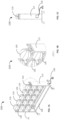
- FIGs. 1A, 1B and 1C show, respectively, an isometric view of a charging pod rack 100, an up-close isometric view of a portion of the charging pod rack 100, and a side view of the charging pod rack 100 according to one embodiment of the present invention.
- the charging pod rack 100 is configured to hold and recharge the internal batteries (not shown) of a plurality of basketballs 110.
- the charging pod rack 100 may comprise a plurality of vertical poles 115 and vertical panels 117 arranged to hold up and support a plurality of parallel horizontal bars 120 connected to the vertical poles 115 spaced and arranged to hold up a plurality of removable wireless charging pods 125.
- FIG. 1A, 1B and 1C show, respectively, an isometric view of a charging pod rack 100, an up-close isometric view of a portion of the charging pod rack 100, and a side view of the charging pod rack 100 according to one embodiment of the present invention.
- the charging pod rack 100 is configured to hold and recharge the internal batteries (not shown)
- each one of the top three rows of the parallel horizontal bars 120 holds up to a total of five wireless charging pods 125, for a total of up to fifteen wireless charging pods 125, which in turn may be used to charge the rechargeable batteries in up to fifteen basketballs 110.
- the bottom row of parallel horizontal bars 120 does not contain any removable wireless charging pods 125. It should be understood, however, that an additional five (5) removable wireless charging pods (not shown) could be placed on the two parallel horizontal bars 120 of the bottom row to bring the total number of removable wireless charging pods 125 to twenty (20) so that the charging pod rack 100 may be used to simultaneously charge the rechargeable batteries in up to twenty (20) basketballs.
- a 120V AC power cable 130 connected to the charging pod rack 100 provides electrical power to the charging pod rack 100, which in turn provides electrical power to each one of the wireless charging pods 125 via a series of electrical power supply cords and connectors electrically coupling the wireless charging pods 125 directly to each other or directly to power supply cords running through the parallel horizontal bars 120.
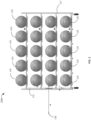
- FIG. 2 shows a front view of a ball charging pod rack 200 holding a total of twenty (20) basketballs on four rows of parallel horizontal bars 220.
- FIG. 3 shows a close-up view of a portion of the ball charging pod rack 205 shown in FIG. 2 .
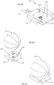
- FIGs. 4A, 4B and 4C show, respectively, an isometric view, a top view and a side view of a wireless charging pod 405 according to an embodiment of the present invention.
- the wireless charging pod 400 comprises a substantially planar body 405 with a substantially hemispherical concave ball receptacle 410 on the top side of the body 405.
- the ball receptacle 410 is configured to receive and hold the bottom part of a basketball (not shown), which contains a rechargeable battery (also not shown) to be charged by the wireless charging pod 400, as will be explained in more detail below.
- the concave shape of the ball receptacle 410 is adapted to fit the bottom of a typical basketball so as to bring a receiving charging coil located inside the basketball as close as possible to a transmitting charging coil located inside the wireless charging pod 400.
- Surrounding the ball receptacle 410 are a set of four light-emitting diodes (LEDs) 415 configured, for example, to turn on (i.e., illuminate), turn off, blink and/or flash in accordance with a set of predetermined colors or patterns to provide an indication to a user that the rechargeable battery inside a basketball resting on the ball receptacle 410 of the wireless charging pod 400 is currently being charged, fully charged, etc.
- LEDs light-emitting diodes
- the LEDs 415 may also be configured to provide an indication to the user whether or not wireless communication components (such as a wireless transceiver) located inside the wireless charging pod 400 are currently communicating with wireless communication components located in the basketball
- the LEDs 415 may also be configured to provide an indication to the user (via colors, illumination or flash patterns) whether or not the receiving charging coil inside the basketball is properly aligned with the transmit charging coil inside the wireless charging pod 400.
- the wireless charging pod 400 may comprise few or more LEDs without departing the scope of the claimed invention, and those LEDs could be positioned in variety of different locations on the wireless charging pod 400.
- Wireless charging pod 400 may also include two power input/output connectors 420 and 422, which permit the wireless charging pod 400 to be used individually with a power cord, or daisy chained together with other wireless charging pods, as illustrated in FIGs. 2 and 3 described above.
- FIGs. 5A, 5B and 5C show, respectively, a side view, a top view and a front view of a mounting shelf 500, which may be used in certain embodiments of the present invention to mount the wireless charging pod 500 on the parallel horizontal bars 120 (not shown in FIGs. 5A, 5B and 5C ) of a compatible charging pod rack, such as the charging pod rack 100 shown in FIG. 1 .
- the mounting shelf 500 preferably includes a base area 510 that is connected to a pair of inverted U-shaped arms 520 and 522 located on opposite sides of the base area 510.
- LEDs 640 are provided around the receptacle 630 to indicate to the user the current charging status of the charging pod assembly 605 and/or basketball 650 when the charging pod assembly 605 is plugged into a power source, such as a 120V power outlet, and an authorized basketball is put on top of the receptacle 630.
- the colors and patterns of light emitted by the LEDs may be selected to convey useful information about the status of the charging operation.
- the LEDs may be configured to emit:
- the basketball receptacle located on top of the charging pod 700 may include a concavity that extends at least partway through the hole 768 in the printed circuit board 750 to further accommodate ensuring that at least a portion of the spherical shape of the basketball 705 can fall below the plane of the printed circuit board 750 and charge transmission coil 773 in the wireless charging pod 700.
- the hole 768 shown in FIG. 7 is circular in shape, it will be understood that the hole (or cutout) also may be configured to accommodate a variety of different shapes associated with non-spherical game devices, such as a football or hockey puck, in order to permit the charge receiving coils in such non-spherical devices to be positioned closer to the charge transmission coil 773 in the wireless charging pod 700.
- FIG. 8 shows a block diagram illustrating, by way of example, the physical and logical components of a wireless charging pod 800 organized and configured to operate according to one embodiment of the present invention.
- FIG. 8 also shows a block diagram of a nearby game device GD-1 that contains a rechargeable battery RBT-1 and a wireless charging receiving circuit WRC-1, wherein the wireless charging receiving circuit WRC-1 in the game device GD-1 is configured to charge the rechargeable battery RBT-1 when electrical current is made to flow through the wireless charging receiving circuit WRC-1 by electromagnetic induction.
- the game device GD-1 may comprise any one of many different types of sporting or gaming devices, tools or equipment that include rechargeable batteries that periodically require recharging.
- the game device GD-1 may comprise, for example, a football, a volley ball, a soccer ball, a tennis ball or racket, a bowling ball, a baseball or a hockey puck or stick, a lacrosse ball or stick, a tennis racket, to name just few examples of game devices that could be constructed with internal electronics and rechargeable batteries.
- the game device GD-1 may also comprise any articles of clothing, headwear or footwear typically worn during games of sport, such as uniforms, cleats, shoes, pads, bands, hats and helmets worn or used for basketball, baseball, football, soccer, etc.
- the wireless charging pods 400, 500, 600, 700 and 800 shown in FIGs. 4 , 5 , 6 , 7 and 8 , respectively, may sometimes be referred to in practice as a "wireless battery charger,” or a “wireless ball charger,” or a “charging device,” or more simply as, a “charger.”
- An individual wireless charging pod of the present invention may be used to charge a single game device, one device at a time.
- the wireless charging pod 800 may be one of a plurality of wireless charging pods that are physically and electronically connected to each other or attached to a rack or other multiple game device charging apparatus, so that a plurality of game devices may be recharged simultaneously by a respective plurality of wireless charging pods on the same rack or apparatus.
- the game device GD-1 840 and the wireless charging pod 800 both include radio frequency transceivers, which are labeled in FIG. 8 as RFT-1 and RFT-2, respectively.
- the radio frequency radios RFT-1 and RFT-2 communicate using a Bluetooth radio frequency protocol.
- the radio frequency radio transceiver RFT-1 in the game device GD-1 840 periodically sends out an advertising signal to advertise its presence to other radio transceivers in the area.
- the charge control program 818 is configured to use data contained in the advertisement to determine the magnitude of the RSSI by calling one or more subroutines included in one or more standard Bluetooth software libraries.
- the predetermined signal strength threshold When the predetermined signal strength threshold is exceeded, it means the game device GD-1 is sufficiently close enough to the wireless charging pod 800 for reliably energizing a wireless charging receiving circuit WRC-1 connected to the rechargeable battery RBT-1 in the game device GD-1 using the wireless charging transmitting circuit WTC-1 in the wireless charging pod 800. Accordingly, the microcontroller unit MCU-2 in the wireless charging pod 800 activates the wireless charging transmitting circuit WTC-1 in the wireless charging pod 800 so that the wireless charging transmitting circuit WTC-1 starts producing an electromagnetic field EF-1 to energize the receiving coil and wireless charging receiving circuit WRC-1 in the game device GD-1, and thereby starts recharging the rechargeable battery RBT-1 in the game device GD-1.
- the microcontroller unit MCU-1 When the rechargeable battery RBT-1 in the game device GD-1 is fully charged, the microcontroller unit MCU-1, operating under the control of the charge control program 838, generates and sends to the wireless charging pod 800 a message indicating that the rechargeable battery RBT-1 in the game device GD-1 is fully recharged.
- the charge control program 818 in the wireless charging pod 800 After receiving the "currently charging" message from the game device GD-1, the charge control program 818 in the wireless charging pod 800 is configured to keep the wireless charging transmitting circuit WTC-1 in the wireless charging pod 800 turned on (and transmitting energy) until it receives the message from the game device GD-1 indicating that the rechargeable battery RBT-1 in the game device GD-1 is fully charged.
- the microcontroller unit MCU-2 in the game device GD-1 operating under the control of the charge control program 838, detects that the rechargeable battery RBT-1 in the game device GD-1 is fully recharged, the microcontroller unit MCU-1 generates and transmits over the first data communications link L1 between the radio frequency transceivers RFT-1 and RFT-2 an "end of charge” message (or signal).
- this condition usually means one of two things.
- the first possibility is that the game device GD-1 is out of the range of the wireless charging transmitting circuit WTC-1 (despite the fact that the RSSI threshold was exceeded).
- the second possibility is that the game device GD-1 is not positioned or oriented correctly (i.e., misaligned) on the receptacle R1 828 of the wireless charging pod 800.
- the game device GD-1 is preferably configured to detect that the rechargeable battery is recharging and, if so, periodically send the "currently charging" confirmation signal over the radio frequency (e.g., Bluetooth) channel L1, and the wireless charging pod 800 periodically re-checks to confirm that the "currently charging” confirmation message is still being received on the data communication channel L1 o ensure the game device GD-1 has detected the electromagnetic field produced by the charging circuit on the rack and is charging. Note that this step could be performed asynchronously.
- the radio frequency e.g., Bluetooth
- the LEDs on the receptacle R1 826 may be configured to turn blue or amber and/or flash to indicate that the device is currently charging.
- the LEDs may also be configured to change color to green when the rechargeable battery RBT-1 is fully charged and the device is ready for use in a game of sport.
- the wireless charging pod 800 will not be able to detect through the radio frequency channel L1 that the game device GD-1 is present, and therefore will not activate the wireless charging circuit WTC-1 to produce the electromagnetic field to energize the wireless charging receiving circuit WTC-1 and start recharging the rechargeable battery RBT-1.
- embodiments of the present invention may be optionally configured to automatically turn on the wireless charging transmission circuit WTC-1 for a few seconds every few minutes (e.g., for 10 seconds out of every 1000 seconds), even when the wireless charging pod 800 has not received an advertisement to tell the wireless charging pod 800 that the rechargeable game device GD-1 is nearby and in need of a recharge.
- These periodic 10-second pulses of the wireless charging transmission circuit WTC-1 will typically be sufficient to energize the wireless charging receiving circuit WRC-1 of the game device GD-1, such that the rechargeable battery RBT-1 of the game device GD-1 will acquire a sufficient amount of stored energy to resume sending out the advertising signals over the first data communications link L1, as well as the charging confirmation messages required to keep the wireless charging transmission circuit WTC-1 of the wireless charging pod 800 continuously activated (as opposed to periodically activated) until the game device is fully charged, or otherwise removed from the range of the wireless charging transmission circuit WTC-1 of the wireless charging pod 800.
- the wireless charging pod 800 may be additionally equipped with a mechanical switch or pressure sensor, located on or associated with the receptacle, which is configured to detect the presence of the game device GD-1, despite the fact that the game device GD-1 is not advertising its presence via the radio frequency transceiver RFT-1.
- the microcontroller unit MCU-1 operating under the control of the charge control program 818, may be configured to periodically activate the wireless charging transmission circuit WTC-1 for a predetermined time period (e.g., for 5 seconds).
- the wireless charging pod 800 may be configured to turn on the wireless charging transmitting circuit WTC-1 for five (5) seconds of every minute until the mechanical switch or the pressure sensor is no longer engaged.
- a printed circuit board (PCB) inside the wireless charging pod 800 may be equipped with a proximity sensor 804 that uses optical technology to detect that an object is on (or very close to) the top of the receptacle R1 826.
- the wireless charging pod 800 may be configured to periodically activate the wireless charging transmission circuit WTC-1 for a predetermined period (e.g., for 2 seconds every minute) until the proximity switch is no longer activated or until the rechargeable battery RBT-1 in the game device GD-1 is sufficiently recharged to permit the game device to resume periodically broadcasting advertisements that can be detected and used by the wireless charging pod 800 to establish communication over the first data communications link L1 (e.g., a reliable Bluetooth connection).
- a predetermined period e.g., for 2 seconds every minute
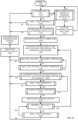
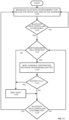
- FIG. 9 shows a flow diagram illustrating by way of example, some of the steps performed by the wireless charging pod to control recharging operations for a nearby game device according to some embodiments of the present invention.
- these steps are carried out by microprocessor unit in the wireless charging pod, the microprocessor unit operating under the control of program instructions in a charge control program, such as the charge control program 818 in FIG. 8 , executed in a volatile memory area on the wireless charging pod.
- a charge control program such as the charge control program 818 in FIG. 8
- the control program begins at step 905 by powering up the wireless charging pod.
- the program checks to see whether it has received, via its radio frequency transceiver, a Bluetooth low energy (BLE) advertisement signal from a nearby game device, such as a basketball. If not, then the program proceeds to step 915, where it checks to see if a ball is detected at the charging receptacle. If a BLE advertisement has not been received, but a basketball has been detected on the receptacle, then the basketball on the receptacle probably has a rechargeable battery that has been completed drained of power, which would explain why the basketball is not broadcasting a BLE advertisement signal.
- BLE Bluetooth low energy
- the control program activates the charging circuit in the wireless charging pod for 2 seconds (see step 920) before returning to step 910 to again check to see if it has received a BLE advertisement signal. If not, and a ball is still being detected on the receptacle, then the control program will continue looping though steps 910, 915 and 920 to periodically activate the charging circuit for 2 seconds over and over again until the detected basketball finally acquires enough power to resume broadcasting BLE advertisements.
- the control program next calculates the received signal strength indication (RSSI) for the advertisement and then determines whether the calculated value of the RSSI is greater than a specified RSSI threshold, such as -35dB. Step 925. If the RSSI threshold is exceeded, then the control program will next determine, in step 930, whether a universally unique identifier (UUID) embedded in the BLE advertisement matches any one of the UUIDs stored in a table stored in the memory of the wireless charging pod.
- RSSI received signal strength indication
- the nearby game device (basketball) that provided the UUID is not authorized for recharging by this charging pod, in which case the basketball will be ignored, and control is passed back to step 910, where the charging pod begins to listen for other BLE advertisements again.
- the control program will establish a Bluetooth connection with the basketball (step 935), activate the charging circuit, enable notifications and wait a specified time interval for the basketball to deliver a message over the Bluetooth connection confirming that the basketball is detecting and using the electromagnetic field produced by the charging circuit to recharge the batter in the basketball (steps 940 and 945). If the confirmation is never received from the basketball, then the charge control program will deactivate the charging circuit to avoid wasting energy (step 950), disconnect the BLE communication channel (step 955), and again return to step 910 to start the process of monitoring the airwaves for BLE advertisements all over again.
- step 945 If it is determined in step 945 that a confirmation has been received from the basketball, and the basketball is recharging due to the activation of the charging circuit by the control program, then the charge control program will again compare the current RSSI for the basketball with the RSSI threshold to make sure the RSSI still exceeds the RSSI threshold (indicating that the basketball is still in range of the electromagnetic field). If the current RSSI does not exceed the RSSI threshold, then the basketball has probably been moved out of rang of the charging circuit and the charge control program will deactivate the charging circuit to avoid wasting energy (step 950), disconnect the BLE communication channel (step 955), and again return to step 910 to start the process of monitoring the Bluetooth airwaves for BLE advertisements all over again.
- the control program next checks to see if a "charge complete” message has been received from the basketball. If not, then the program loops back to step 945, where the system again determines, based on messages received (or not received) from the basketball, whether the battery in the basketball is currently recharging.
- the program deactivates the charging circuit (see step 970) and then enters a loop where it repeatedly queries the basketball over the Bluetooth connection to determine when the charge on the battery of the basketball falls below 98% (step 975) and also attempts to verify that the current RSSI for the basketball remains greater than the RSS threshold (indicating the basketball is still within range).
- the control program will continuously loop between steps 975 and 980 until the battery is no longer at least 98% full or the RSSI drops below the RSSI threshold.
- the control program will return to step 940, where it will again perform the steps of activating the charging circuit, looking for a confirmation that the battery is being charged by the electromagnetic field produced by the activated electromagnetic field, and then, while the charging circuit remains on, periodically confirming that the current RSSI remains above the specified RSSI threshold (the ball is close enough to the charger to be recharged) and the battery is at least 98% full to capacity.
- FIG. 10 shows a modified version of the algorithm depicted in FIG. 9 , wherein the modified version of the algorithm includes steps for ensuring that the game device, and therefore the components of the charge receiving circuit in the game device, are properly aligned on the receptacle of the wireless charging pod.
- the MCU in the game device is configured to measure and monitor the magnitude of the voltage generated on its charging coil and transmit that voltage magnitude over the data communications link (e.g., the Bluetooth data communications link L1) to the wireless charging pod so that the wireless charging pod can determine how well the game device's receiving coil is aligned with the receiving coil on the charging receptacle.
- the wireless charging pod may be configured to display an indication of the degree of alignment to the user by changing the color and/or pulse rate of LEDs located on or near the receptacle.
- the wireless charging pod may also be configured to transmit a message about the current status of the alignment to another device.
- the magnitude of the voltage generated on the charge receiving coil of the game device during a charging operation varies in proportion to how well the charge receiving coil is aligned with the charge transmitting coil on the wireless charging pod.
- the magnitude of the voltage will be greatest when the charge receiving coil is directly above the charge transmitting coil, and will gradually decrease as the game device is rotated and/or translated to different positions on the receptacle and the charge receiving coil is moved off-center relative the charge transmitting coil.
- embodiments of the present invention are configured to activate and/or deactivate the charge transmitting circuit and provide warnings and/or status indications about the quality of the alignment to the user depending on whether the distance and angle between the charge receiving coil and the charge transmitting coil falls inside or outside a predetermined alignment window defined by a specified "unaligned" threshold and a specified "aligned” threshold.
- the steps in the algorithm represented by the flow diagram in FIG. 10 are substantially the same as the steps in the algorithm represented by the flow diagram of FIG. 9 , except that the algorithm represented by the flow diagram of FIG. 10 adds two additional steps (corresponding to two additional decision boxes 1045 and 1050).
- the first additional step represented in FIG. 10 by decision box 1045, determines whether the magnitude of the voltage generated on the ball's charge receiving coil is less than a specified predetermined "unaligned" threshold.
- the second additional step, represented in FIG. 10 by decision block 1050 determines whether the magnitude of the voltage generated on the ball's charge receiving coil exceeds a specified predetermined "aligned" threshold.
- the reason for adding two additional steps, instead of adding only a single additional step, is because the game device charge rate varies with how well the charge receiving coil is aligned with the charge transmitting coil. For example, if the charge receiving coil in the game device is barely aligned with the charge transmitting coil in the wireless charging pod, then the rechargeable battery in the game device may charge, but it will charge at a reduced rate, and may take many hours or days to charge to its full capacity. If the charge receiving coil in the game device is well-aligned with the charge transmitting coil in the wireless charging pod, then the rechargeable battery in the game device will charge at a much faster rate.
- the separate aligned and unaligned thresholds represent the two different scenarios. Exemplary (typical) values for the two alignment threshold voltages are 8-10 V for the aligned threshold and 5 V for the unaligned threshold.
- alignment (or misalignment) of the game device may be determined and/or reported to the user by measuring and monitoring the magnitude of the current flowing through the charge receiving coil instead of measuring and monitoring the voltage generated on the charge receiving coil, and then activating and deactivating the charge transmitting circuit and/or providing alignment/misalignment notifications and warnings if and when the magnitude of the measured and monitored current rises above a specified minimum amperage threshold for good alignment or falls below a predetermined maximum amperage threshold for bad alignment.
- FIG. 11 shows a flow diagram illustrating by way of example, some of the steps carried out by a charge control program running on the game device to control the communication and status reporting by the game device during charging operations in accordance with some embodiments of the present invention.
- the charge control program on the game device (such as a basketball with a rechargeable battery) includes program instructions that periodically broadcasts a Bluetooth advertisement until the advertisement is recognized by a wireless charging pod and a Bluetooth data communications link is established between the game device and the wireless charging pod (see steps 1105 and 1110 in FIG. 11 ).
- the Bluetooth advertisements typically include a universally unique identifier (UUID) for the game device, which uniquely identifies the individual device manufactured or sold by a certain company, and/or a MAC address, which uniquely identifies all Bluetooth devices, regardless of manufacturer.
- UUID universally unique identifier
- the wireless charging pod uses the UUID and/or MAC address to determine whether the game device is authorized for charging by that wireless charging pod.
- the charge control program running on the game device will cause the game device to stop broadcasting Bluetooth advertisements whenever a Bluetooth communications link has been established between the game device and a wireless charging pod.
Landscapes
- Engineering & Computer Science (AREA)
- Power Engineering (AREA)
- Computer Networks & Wireless Communication (AREA)
- Signal Processing (AREA)
- Physics & Mathematics (AREA)
- Electromagnetism (AREA)
- Quality & Reliability (AREA)
- Health & Medical Sciences (AREA)
- General Health & Medical Sciences (AREA)
- Physical Education & Sports Medicine (AREA)
- Charge And Discharge Circuits For Batteries Or The Like (AREA)
- Secondary Cells (AREA)
Claims (6)
- Socle de module support de recharge sans fil pour deux, ou davantage, dispositifs de jeu, lesdits deux, ou davantage, dispositifs de jeu comprenant chacun une batterie rechargeable (RBT), une unité de microcontrôleur de dispositif (DMCU), un émetteur-récepteur radiofréquence (DRFT) et un circuit de réception de charge sans fil (WCRC) couplé électriquement à la batterie rechargeable (RBT) de telle sorte que l'activation du circuit de réception de charge sans fil (WCRC) augmente la charge (V) stockée dans la batterie rechargeable (RBT), le socle de module support de recharge sans fil comprenant :a) un module support de recharge sans fil comprenant une première mémoire, un premier seuil d'intensité de signal de réception (RSST-1) stocké dans la première mémoire, et un premier réceptacle (R1) configuré pour recevoir un premier dispositif de jeu (GD-1) ;b) un premier circuit de transmission de recharge sans fil (WCTC-1), connecté au premier réceptacle de dispositif (R1), qui produit un premier champ électromagnétique (EF-1) qui alimentera un premier circuit de réception de charge sans fil (WCRC-1) dudit premier dispositif de jeu (GD-1) si le premier circuit de transmission de charge sans fil (WCTC-1) est activé tandis que le premier circuit de réception de charge sans fil (WCRC-1) dudit premier dispositif de jeu (GD-1) se trouve à portée du premier champ électromagnétique (EF-1) ;c) un premier émetteur-récepteur radiofréquence (RFT-1), connecté au premier module support de charge sans fil, configuré pour (A) établir une première liaison de communication de données (L1) pour échanger des messages avec un premier émetteur-récepteur radiofréquence de dispositif (DRFT-1) sur ledit premier dispositif de jeu (GD-1), et (B) recevoir, par l'intermédiaire de la première liaison de communication de données (L1), un premier message (M1) transmis par ledit premier dispositif de jeu (GD-1) ;d) une première unité à microcontrôleur (MCU-1) qui commande l'activation et la désactivation du premier circuit de transmission de charge sans fil (WCTC-1) du premier réceptacle (R1) ;e) un deuxième module support de charge sans fil comprenant une deuxième mémoire, un deuxième seuil d'intensité du signal de réception (RSST-2) stocké dans la deuxième mémoire, un deuxième réceptacle (R2) configuré pour recevoir un deuxième dispositif de jeu (GD-2) ;f) un deuxième circuit de transmission de charge sans fil (WCTC-2), connecté au deuxième réceptacle de balle (R2), qui produit un deuxième champ électromagnétique (EF-2) qui alimentera un deuxième circuit de réception de charge sans fil (WCRC-2) dudit deuxième dispositif de jeu (GD-2) si le deuxième circuit de transmission de charge sans fil (WCTC-2) est activé tandis que le deuxième circuit de réception de charge sans fil (WCRC-2) dudit deuxième dispositif de jeu (GD-2) se trouve à portée du deuxième champ électromagnétique (EF-2) ;g) un deuxième émetteur-récepteur radiofréquence (RFT-2), connecté au deuxième module support de charge sans fil, configuré pour (A) établir une deuxième liaison de communication de données (L2) pour échanger des messages avec un deuxième émetteur-récepteur radiofréquence (DRFT-2) sur ledit deuxième dispositif de jeu (GD-2), et (B) recevoir, par l'intermédiaire de la deuxième liaison de communication de données (L2), un deuxième message (M2) transmis par ledit deuxième dispositif de jeu (GD-2) ;h) une deuxième unité à microcontrôleur (MCU-2) qui commande l'activation et la désactivation du deuxième circuit de transmission de charge sans fil (WCTC-2) connecté au deuxième réceptacle (R2) ;i) un premier programme de commande de charge dans la première mémoire, le premier programme de commande de charge comprenant des instructions de programme qui, lorsqu'elles sont exécutées par la première unité à microcontrôleur (MCU-1) unité, amènent la première unité de microcontrôleur (MCU-1) à(i) déterminer une première indication d'intensité du signal reçu (RSSI-1) pour la première liaison de communication de données (L1) sur la base du premier message (M1),(ii) comparer la première indication d'intensité du signal reçu (RSSI-1) au premier seuil d'intensité du signal reçu (RSST-1), et(iii) activer le premier circuit de transmission de charge sans fil (WCTC-1) connecté au premier réceptacle (R1) lorsque la première indication d'intensité du signal reçu (RSSI-1) est supérieure ou égale au premier seuil d'intensité du signal reçu (RSST-1), indiquant ainsi que le premier dispositif de jeu (GD-1) se trouve à portée du socle de module support de charge sans fil ; etj) un deuxième programme de commande de charge dans la deuxième mémoire, le deuxième programme de commande de charge comprenant des instructions de programme qui, lorsqu'elles sont exécutées par la deuxième unité à microcontrôleur (MCU-2) unité ou la deuxième unité à microcontrôleur (MCU-2), amènent la deuxième unité à microcontrôleur (MCU-2) à(i) déterminer une deuxième indication d'intensité du signal reçu (RSSI-2) pour la deuxième liaison de communication de données (L2) sur la base du deuxième message (M2),(ii) comparer la deuxième indication d'intensité du signal reçu (RSSI-2) au deuxième seuil d'intensité du signal reçu (RSST-2), et(iii) activer le deuxième circuit de transmission de charge sans fil (WCTC-2) connecté au deuxième réceptacle (R2) lorsque la deuxième indication d'intensité du signal reçu (RSSI-2) est supérieure ou égale au deuxième seuil d'intensité du signal reçu (RSST-2), indiquant ainsi que le deuxième dispositif de jeu (GD-2) se trouve à portée du socle de module support de charge sans fil ;k) moyennant quoi(i) le premier circuit de réception de charge sans fil (WCRC-1) dudit premier dispositif de jeu (GD-1) est alimenté par le premier champ électromagnétique (EF-1) produit par le premier circuit de transmission de charge sans fil (WCTC-1) du premier module support de charge sans fil, augmentant ainsi la charge (V1) stockée dans une première batterie rechargeable (RBT-1) connectée audit premier dispositif de jeu (GD-1), et(ii) le deuxième circuit de réception de charge sans fil (WCRC-2) dudit deuxième dispositif de jeu (GD-2) est alimenté par le deuxième champ électromagnétique (EF-2) produit par le deuxième circuit de transmission de charge sans fil (WCTC-2) du deuxième module support de charge sans fil, augmentant ainsi la charge (V2) stockée dans une deuxième batterie rechargeable (RBT-2) connectée audit deuxième dispositif de jeu (GD-2).
- Socle de module support de charge sans fil selon la revendication 1, dans lequel le premier seuil d'intensité du signal reçu (RSST-1) et le deuxième seuil d'intensité du signal reçu (RSST-2) ont la même valeur.
- Socle de module support de charge sans fil selon la revendication 1, dans lequel :a) le premier champ électromagnétique (EF-1) alimente le deuxième circuit de réception de charge sans fil (WCRC-2) dudit deuxième dispositif de jeu (GD-2) si le premier circuit de transmission de charge sans fil (WCTC-1) est activé tandis que le deuxième circuit de réception de charge sans fil (WCRC-2) dudit deuxième dispositif de jeu (GD-2) se trouve à portée du premier champ électromagnétique (EF-1) ; etb) le deuxième champ électromagnétique (EF-2) alimente le premier circuit de réception de charge sans fil (WCRC-1) dudit premier dispositif de jeu (GD-1) si le deuxième circuit de transmission de charge sans fil (WCTC-2) est activé tandis que le premier circuit de réception de charge sans fil (WCRC-1) dudit premier dispositif de jeu (GD-1) se trouve à portée du deuxième champ électromagnétique (EF-2).
- Socle de module support de charge sans fil selon la revendication 3, dans lequel le premier programme de commande de charge comprend en outre des instructions de programme qui, lorsqu'elles sont exécutées par la première unité à microcontrôleur (MCU-1) sur le premier module support de charge sans fil, empêchent l'activation du premier circuit de charge sans fil (WCTC-1) connecté au premier réceptacle (R1) lorsque la première unité à microcontrôleur (MCU-1) détermine que la première indication d'intensité du signal reçu (RSSI-1) pour la première liaison de communication de données (L1) est inférieure au premier seuil d'intensité du signal reçu (RSST-1).
- Socle de module support de charge sans fil selon la revendication 3, dans lequel le deuxième programme de commande de charge comprend en outre des instructions de programme qui, lorsqu'elles sont exécutées par la deuxième unité à microcontrôleur (MCU-2) sur le deuxième module support de charge sans fil, empêchent l'activation du deuxième circuit de charge sans fil (WCTC-2) connecté au deuxième réceptacle (R2) lorsque la deuxième unité à microcontrôleur (MCU-2) détermine que que la deuxième indication d'intensité du signal reçu (RSSI-2) pour la deuxième liaison de communication de données (L2) est inférieure au deuxième seuil d'intensité du signal reçu (RSST-2).
- Socle de module support de charge sans fil selon la revendication 1, comprenant en outre :un premier capteur de proximité configuré pour détecter en continu si ledit premier dispositif de jeu (GD-1) est sur ou à proximité du premier réceptacle (R1) et, en réponse à une détection par le premier capteur de proximité que ledit premier dispositif de jeu (GD-1) est sur ou à proximité du premier réceptacle (R1), pour identifier automatiquement un premier dispositif de jeu le plus proche (GD-1) sur la base du courant (RSSI-1) pour ledit premier dispositif de jeu le plus proche (GD-1) ; etun deuxième capteur de proximité configuré pour détecter en continu si ledit deuxième dispositif de jeu (GD-2) est sur ou à proximité du deuxième réceptacle (R2) et, en réponse à une détection par le deuxième capteur de proximité que ledit deuxième dispositif de jeu (GD-2) est sur ou à proximité du deuxième réceptacle (R2), pour identifier automatiquement un deuxième dispositif de jeu le plus proche (GD-2) sur la base du courant (RSSI-2) pour ledit deuxième dispositif de jeu le plus proche (GD-2).
Applications Claiming Priority (3)
| Application Number | Priority Date | Filing Date | Title |
|---|---|---|---|
| US201862648443P | 2018-03-27 | 2018-03-27 | |
| PCT/US2019/024411 WO2019191315A1 (fr) | 2018-03-27 | 2019-03-27 | Nacelle de charge sans fil et bâti de nacelle de charge pour dispositifs de jeu ayant des batteries rechargeables |
| EP19774698.5A EP3756269B1 (fr) | 2018-03-27 | 2019-03-27 | Nacelle et procédé de charge sans fil pour dispositifs de jeu ayant des batteries rechargeables |
Related Parent Applications (2)
| Application Number | Title | Priority Date | Filing Date |
|---|---|---|---|
| EP19774698.5A Division EP3756269B1 (fr) | 2018-03-27 | 2019-03-27 | Nacelle et procédé de charge sans fil pour dispositifs de jeu ayant des batteries rechargeables |
| EP19774698.5A Division-Into EP3756269B1 (fr) | 2018-03-27 | 2019-03-27 | Nacelle et procédé de charge sans fil pour dispositifs de jeu ayant des batteries rechargeables |
Publications (2)
| Publication Number | Publication Date |
|---|---|
| EP4156458A1 EP4156458A1 (fr) | 2023-03-29 |
| EP4156458B1 true EP4156458B1 (fr) | 2025-07-09 |
Family
ID=68053925
Family Applications (2)
| Application Number | Title | Priority Date | Filing Date |
|---|---|---|---|
| EP22207473.4A Active EP4156458B1 (fr) | 2018-03-27 | 2019-03-27 | Nacelle de charge sans fil et support de nacelle de charge pour dispositifs de jeu à batteries rechargeables |
| EP19774698.5A Active EP3756269B1 (fr) | 2018-03-27 | 2019-03-27 | Nacelle et procédé de charge sans fil pour dispositifs de jeu ayant des batteries rechargeables |
Family Applications After (1)
| Application Number | Title | Priority Date | Filing Date |
|---|---|---|---|
| EP19774698.5A Active EP3756269B1 (fr) | 2018-03-27 | 2019-03-27 | Nacelle et procédé de charge sans fil pour dispositifs de jeu ayant des batteries rechargeables |
Country Status (8)
| Country | Link |
|---|---|
| US (2) | US10862350B2 (fr) |
| EP (2) | EP4156458B1 (fr) |
| CN (2) | CN113381522B (fr) |
| AU (1) | AU2019244111B2 (fr) |
| BR (1) | BR112020019517B8 (fr) |
| ES (1) | ES2952374T3 (fr) |
| RS (1) | RS64363B1 (fr) |
| WO (1) | WO2019191315A1 (fr) |
Families Citing this family (20)
| Publication number | Priority date | Publication date | Assignee | Title |
|---|---|---|---|---|
| WO2018126027A1 (fr) * | 2016-12-28 | 2018-07-05 | Hubbell Incorporated | Système de charge modulaire |
| US20180345086A1 (en) * | 2017-05-31 | 2018-12-06 | Dozie Mbonu | Basketball Training Apparatus |
| US10879723B2 (en) * | 2018-12-10 | 2020-12-29 | Xentris Wireless Llc | Exchangeable interface charging dock |
| US11310118B2 (en) * | 2019-01-21 | 2022-04-19 | Hewlett Packard Enterprise Development Lp | Tracking randomized addresses in bluetooth devices |
| JP7142176B2 (ja) * | 2019-06-17 | 2022-09-26 | ディーディースポーツ,インコーポレイテッド | 衝撃吸収キャリアに収容された電子装置を有するスポーツボール |
| GB2591216B (en) * | 2019-10-25 | 2022-08-31 | Sportable Tech Ltd | Apparatus for an inflatable sports ball |
| JP7408401B2 (ja) * | 2020-01-09 | 2024-01-05 | 東芝テック株式会社 | カート給電装置 |
| US12599731B2 (en) * | 2020-02-03 | 2026-04-14 | 10Xbeta | System and method for sensing usage of a controlled medical therapy device |
| FR3114472B1 (fr) * | 2020-09-18 | 2022-12-09 | St Microelectronics Ltd | Charge NFC |
| CN114204699B (zh) | 2020-09-18 | 2024-11-01 | 意法半导体有限公司 | Nfc充电 |
| CN112261638B (zh) * | 2020-09-30 | 2022-08-12 | 厦门亿联网络技术股份有限公司 | 快速识别双模蓝牙设备的方法、装置、ios设备及介质 |
| US11527912B2 (en) * | 2021-02-01 | 2022-12-13 | Nucurrent, Inc. | Shaped coil for wireless power transmission system coupling |
| JPWO2022254710A1 (fr) * | 2021-06-04 | 2022-12-08 | ||
| CN115622271B (zh) * | 2021-07-15 | 2025-10-14 | 台达电子企业管理(上海)有限公司 | 无线充电发射装置、方法 |
| CN113975707A (zh) * | 2021-12-08 | 2022-01-28 | 广东沃莱科技有限公司 | 一种电子跳绳智能管理系统 |
| US20230198306A1 (en) * | 2021-12-16 | 2023-06-22 | Bennet Langlotz | Wireless device charger |
| CN113993115B (zh) * | 2021-12-27 | 2022-04-01 | 飞天诚信科技股份有限公司 | 自动解锁屏幕方法、装置、电子设备及可读存储介质 |
| US20240340368A1 (en) * | 2023-04-04 | 2024-10-10 | Ravi Persaud | Smart Eyewear Device |
| CN120768891A (zh) * | 2024-06-21 | 2025-10-10 | 荣耀终端股份有限公司 | 免拆盒补电升级方法、系统及存储介质 |
| US20260007205A1 (en) * | 2025-03-05 | 2026-01-08 | Guangzhou Zhengtao Enterprise Management Co., Ltd. | Shoe |
Family Cites Families (148)
| Publication number | Priority date | Publication date | Assignee | Title |
|---|---|---|---|---|
| US4438588A (en) | 1982-09-29 | 1984-03-27 | Martin John E | Remote control ball |
| US5316293A (en) | 1993-04-26 | 1994-05-31 | Hamilton David H | Signal emitting ball |
| US5293354A (en) | 1993-08-12 | 1994-03-08 | Costabile Michael J | Remotely actuatable sports timing system |
| US5697791A (en) | 1994-11-29 | 1997-12-16 | Nashner; Lewis M. | Apparatus and method for assessment and biofeedback training of body coordination skills critical and ball-strike power and accuracy during athletic activitites |
| US5526326A (en) | 1994-12-20 | 1996-06-11 | Creata Inc. | Speed indicating ball |
| US5776018A (en) | 1995-11-17 | 1998-07-07 | Solopractice, Inc. | Basketball collection, passing and shot analysis system |
| US5871406A (en) | 1997-09-23 | 1999-02-16 | Worrell; W. Robert | Golf swing timing process |
| AUPP027997A0 (en) | 1997-11-10 | 1997-12-04 | Cooper, John Mary | Ball game |
| US6148271A (en) | 1998-01-14 | 2000-11-14 | Silicon Pie, Inc. | Speed, spin rate, and curve measuring device |
| US6177861B1 (en) | 1998-07-17 | 2001-01-23 | Lucent Technologies, Inc | System for short range wireless data communication to inexpensive endpoints |
| JP2996650B1 (ja) | 1998-08-26 | 2000-01-11 | セノー株式会社 | バスケット台 |
| US6620057B1 (en) | 1999-04-15 | 2003-09-16 | Flite Traxx, Inc. | System for locating golf balls |
| EP1069526A3 (fr) | 1999-07-12 | 2005-03-30 | Matsushita Electric Industrial Co., Ltd. | Dispositif de discrimination des objets mobiles pour l'acquisition rapide des données qui sont envoyées par des ondes radios modulées avec des tranpondeurs qui sont à l'intérieur d'une région de communication d'un appareil d'interrogation |
| US6944148B1 (en) | 1999-09-10 | 2005-09-13 | Pulse-Link, Inc. | Apparatus and method for managing variable-sized data slots within a time division multiple access frame |
| US6597683B1 (en) | 1999-09-10 | 2003-07-22 | Pulse-Link, Inc. | Medium access control protocol for centralized wireless network communication management |
| US6389368B1 (en) | 1999-10-01 | 2002-05-14 | Randal R. Hampton | Basketball goal sensor for detecting shots attempted and made |
| US7133396B1 (en) | 2000-03-06 | 2006-11-07 | Texas Instruments Incorporated | Dynamic assignment of retransmission slots for enhanced quality in wireless communication links |
| WO2001084861A1 (fr) | 2000-04-28 | 2001-11-08 | Hi-G-Tek Ltd. | Dispositif et procedes de communication cellulaire |
| US6280352B1 (en) | 2000-08-23 | 2001-08-28 | Athletics Project Inc. | Apparatus and method for performing timed basketball drills |
| US20020107092A1 (en) | 2001-02-06 | 2002-08-08 | Karen Gottlieb-Myers | System for, and method of, indicating to a child the accuracy of shooting a basketball to make a basket |
| DE10107797A1 (de) | 2001-02-15 | 2002-08-29 | Hielscher Frank | Spiel- und Sportgerät |
| US6418179B1 (en) | 2001-05-21 | 2002-07-09 | Frank Shieh | Score counter by sensing route of basketball shots |
| US6582329B1 (en) | 2001-06-19 | 2003-06-24 | Edwin Cabrera | Hoop for indicating when a basketball passes therethrough |
| AU2002324969A1 (en) | 2001-09-12 | 2003-03-24 | Pillar Vision Corporation | Trajectory detection and feedback system |
| US8409024B2 (en) | 2001-09-12 | 2013-04-02 | Pillar Vision, Inc. | Trajectory detection and feedback system for golf |
| US20030054905A1 (en) | 2001-09-14 | 2003-03-20 | King Willie A. | Monitoring computer system for court and field ball games |
| US6758769B2 (en) | 2002-03-25 | 2004-07-06 | Webb T. Nelson | Electronic sound effect assembly for use on a sport's goal net |
| DE10231782A1 (de) | 2002-07-13 | 2004-01-22 | Walter Linner | Anlage für Wettkampfspiel mit Basketball und Basketballkorb |
| US8183827B2 (en) | 2003-01-28 | 2012-05-22 | Hewlett-Packard Development Company, L.P. | Adaptive charger system and method |
| US7005965B2 (en) | 2003-02-14 | 2006-02-28 | Winbond Electronics Corporation | Radio frequency identification device |
| US7182704B2 (en) | 2003-12-10 | 2007-02-27 | Avery Levy | Automated ball game training and playing system |
| US20050223799A1 (en) | 2004-03-31 | 2005-10-13 | Brian Murphy | System and method for motion capture and analysis |
| JP4578139B2 (ja) | 2004-04-13 | 2010-11-10 | 富士通株式会社 | 所定の情報を受信する情報処理装置、プログラム、記憶媒体および方法 |
| US7095312B2 (en) | 2004-05-19 | 2006-08-22 | Accurate Technologies, Inc. | System and method for tracking identity movement and location of sports objects |
| US7758523B2 (en) | 2004-05-24 | 2010-07-20 | Kineteks Corporation | Remote sensing shoe insert apparatus, method and system |
| US7091863B2 (en) | 2004-06-03 | 2006-08-15 | Gary Ravet | System and method for tracking the movement and location of an object in a predefined area |
| US7949295B2 (en) | 2004-08-18 | 2011-05-24 | Sri International | Automated trainee monitoring and performance evaluation system |
| US7375616B2 (en) | 2004-09-08 | 2008-05-20 | Nokia Corporation | Electronic near field communication enabled multifunctional device and method of its operation |
| DE102004045176B4 (de) | 2004-09-17 | 2011-07-21 | Adidas International Marketing B.V. | Blase |
| WO2006038163A1 (fr) | 2004-10-01 | 2006-04-13 | Nortel Networks Limited | Segmentation et groupage dans un reseau de detection |
| US20060105857A1 (en) | 2004-11-17 | 2006-05-18 | Stark David A | Athletic ball telemetry apparatus and method of use thereof |
| US7254516B2 (en) | 2004-12-17 | 2007-08-07 | Nike, Inc. | Multi-sensor monitoring of athletic performance |
| JP2006229583A (ja) * | 2005-02-17 | 2006-08-31 | Eastman Kodak Co | 通信システム及びデジタルカメラ並びにドック装置 |
| CN1891321A (zh) * | 2005-06-30 | 2007-01-10 | 英泰克公司 | 具有可再充电电池系统的视频游戏控制器 |
| CA2623083A1 (fr) | 2005-07-08 | 2007-01-18 | Ian Alexander Mackay | Jeu |
| US20090117525A1 (en) | 2005-07-13 | 2009-05-07 | Pando Technologies, Llc | Sensory Coordination System for Sports, Therapy and Exercise |
| US7771293B1 (en) | 2005-11-22 | 2010-08-10 | Kayode Teddy Vann | Basketball shooting training aid and method for its use |
| US20070135243A1 (en) | 2005-12-12 | 2007-06-14 | Larue Michael B | Active sports tracker and method |
| US20070173355A1 (en) | 2006-01-13 | 2007-07-26 | Klein William M | Wireless sensor scoring with automatic sensor synchronization |
| US20080015061A1 (en) | 2006-07-11 | 2008-01-17 | Klein William M | Performance monitoring in a shooting sport using sensor synchronization |
| WO2007084850A2 (fr) | 2006-01-13 | 2007-07-26 | Klein William M | Surveillance des performances dans un sport de tir a l'aide de la synchronisation de capteurs |
| US20070173349A1 (en) * | 2006-01-26 | 2007-07-26 | Eng Wing S | Light emitting golf ball, kit and system |
| US20070219024A1 (en) | 2006-03-16 | 2007-09-20 | Allegre Luis Edgar G | Dribbling and ball control sports training system and method |
| WO2007130057A1 (fr) | 2006-05-09 | 2007-11-15 | Microsoft Corporation | Équipement sportif communiquant intelligent |
| US7771320B2 (en) | 2006-09-07 | 2010-08-10 | Nike, Inc. | Athletic performance sensing and/or tracking systems and methods |
| DE102007001820B3 (de) | 2006-10-12 | 2008-01-24 | Cairos Technologies Ag | Konzept zur Erkennung eines Kontakts mit einem Spielgerät |
| US8079925B2 (en) | 2006-10-12 | 2011-12-20 | Cairos Technologies Ab | Concept for activating a game device |
| US7843348B2 (en) | 2007-01-19 | 2010-11-30 | Alliance Coal, Llc | System and method for tracking personnel and equipment |
| US7698101B2 (en) | 2007-03-07 | 2010-04-13 | Apple Inc. | Smart garment |
| US7625314B2 (en) | 2007-04-30 | 2009-12-01 | Nike, Inc. | Adaptive training system with aerial mobility system |
| US20080274844A1 (en) | 2007-05-03 | 2008-11-06 | Emd3 | False activation reducing centrifugal activation system |
| US8248212B2 (en) | 2007-05-24 | 2012-08-21 | Sirit Inc. | Pipelining processes in a RF reader |
| US7944905B2 (en) | 2007-05-29 | 2011-05-17 | Motorola Solutions, Inc. | Method for dynamically identifying locations of mobile nodes in a time division multiple access based ad hoc communication network |
| US8360904B2 (en) | 2007-08-17 | 2013-01-29 | Adidas International Marketing Bv | Sports electronic training system with sport ball, and applications thereof |
| US8702430B2 (en) | 2007-08-17 | 2014-04-22 | Adidas International Marketing B.V. | Sports electronic training system, and applications thereof |
| US8221290B2 (en) | 2007-08-17 | 2012-07-17 | Adidas International Marketing B.V. | Sports electronic training system with electronic gaming features, and applications thereof |
| US20090111616A1 (en) | 2007-10-30 | 2009-04-30 | Russell Corporation | System for detecting and tracking statistics of a game |
| US7998004B2 (en) | 2008-01-24 | 2011-08-16 | Klein William M | Real-time wireless sensor scoring |
| EP2260453A4 (fr) | 2008-02-14 | 2016-03-23 | Infomotion Sports Technologies Inc | Analyse électronique d'une performance athlétique |
| US8279051B2 (en) | 2008-04-14 | 2012-10-02 | Naser Mohammed Khan | Realtime coaching system |
| WO2009134868A2 (fr) | 2008-04-29 | 2009-11-05 | Alliance Coal, Llc | Système et procédé pour une détection de proximité |
| US8465382B2 (en) | 2008-06-02 | 2013-06-18 | Rashan Christopher Moye | Electronic basketball shooting coach |
| US8249254B1 (en) | 2008-09-30 | 2012-08-21 | Id Coach, Llc | Apparatus, system and method for reporting a player's game plays during a game |
| US7920052B2 (en) | 2008-10-03 | 2011-04-05 | Michael Joseph Costabile | Sports monitoring and tracking system |
| DE102008058943B3 (de) | 2008-11-25 | 2010-05-12 | Adidas International Marketing B.V. | Blase für einen Ball |
| US8628453B2 (en) | 2008-12-05 | 2014-01-14 | Nike, Inc. | Athletic performance monitoring systems and methods in a team sports environment |
| US8231506B2 (en) | 2008-12-05 | 2012-07-31 | Nike, Inc. | Athletic performance monitoring systems and methods in a team sports environment |
| AU2010229693B2 (en) | 2009-03-27 | 2014-04-03 | Russell Brands, Llc | Monitoring of physical training events |
| US8452235B2 (en) * | 2009-03-28 | 2013-05-28 | Qualcomm, Incorporated | Tracking receiver devices with wireless power systems, apparatuses, and methods |
| US8477046B2 (en) | 2009-05-05 | 2013-07-02 | Advanced Technologies Group, LLC | Sports telemetry system for collecting performance metrics and data |
| CN201510739U (zh) * | 2009-07-16 | 2010-06-23 | 深圳市三子科技有限公司 | 可无线充电的游戏装置组合 |
| US20110054782A1 (en) | 2009-08-27 | 2011-03-03 | Kaahui Keaka K A | Method and apparatus of measuring and analyzing user movement |
| US8525472B2 (en) * | 2009-09-30 | 2013-09-03 | Accurate Technologies Inc. | Inductive charging system in communications with objects being charged and with microprocessor controlled diagnostics |
| US8687546B2 (en) | 2009-12-28 | 2014-04-01 | Intel Corporation | Efficient uplink SDMA operation |
| US8248981B2 (en) | 2010-01-21 | 2012-08-21 | Eigent Technologies, Inc. | Method and apparatus for low cost, long range, power efficient, wireless system with enhanced functionality |
| US8786415B2 (en) | 2010-02-24 | 2014-07-22 | Sportvision, Inc. | Tracking system using proximity and/or presence |
| US9401178B2 (en) | 2010-08-26 | 2016-07-26 | Blast Motion Inc. | Event analysis system |
| US8845461B2 (en) | 2010-09-01 | 2014-09-30 | Jason Duke | Hoop tracker |
| US8517870B2 (en) | 2010-09-07 | 2013-08-27 | Infomotion Sports Technologies, Inc. | Electronic component enclosure for an inflated object |
| KR101767794B1 (ko) | 2011-02-17 | 2017-08-11 | 나이키 이노베이트 씨.브이. | 위치 맵핑 |
| US9381420B2 (en) | 2011-02-17 | 2016-07-05 | Nike, Inc. | Workout user experience |
| US9511278B2 (en) | 2011-03-09 | 2016-12-06 | Andamiro Co., Ltd. | Basketball game console, network basketball game console using the same, and basketball method |
| US9391671B2 (en) * | 2011-05-06 | 2016-07-12 | Samsung Electronics Co., Ltd. | Wireless power transmission and charging system and method thereof |
| US20120316843A1 (en) | 2011-06-08 | 2012-12-13 | Cobra Golf Incorporated | Systems and methods for communicating sports-related information |
| US9351099B2 (en) | 2011-10-18 | 2016-05-24 | Lg Electronics Inc. | Scheduling method in wireless communication system and device therefor |
| WO2013089485A1 (fr) * | 2011-12-15 | 2013-06-20 | Samsung Electronics Co., Ltd. | Appareil et procédé de transmission sans fil de courant électrique |
| US20130167290A1 (en) | 2011-12-30 | 2013-07-04 | Ariel BEN EZRA | Sensor activated ball and sport accessory with computer functionalities |
| US9233287B2 (en) | 2012-01-04 | 2016-01-12 | Massachusetts Institute Of Technology | Force-sensing net |
| KR101949800B1 (ko) | 2012-01-16 | 2019-02-19 | 삼성전자주식회사 | 동적 프로토콜을 재구성하기 위하여 슈퍼 프레임을 사용하는 통신 장치 및 동적 프로토콜을 재구성하기 위한 센서 노드 및 허브 장치의 메시지 교환 방법 |
| US9755437B2 (en) | 2012-04-25 | 2017-09-05 | Nokia Technologies Oy | Method, apparatus, and computer program product for wireless charging detection |
| US9900057B2 (en) * | 2012-07-06 | 2018-02-20 | Energous Corporation | Systems and methods for assigning groups of antenas of a wireless power transmitter to different wireless power receivers, and determining effective phases to use for wirelessly transmitting power using the assigned groups of antennas |
| WO2014063159A2 (fr) * | 2012-10-19 | 2014-04-24 | Witricity Corporation | Détection de corps étranger dans des systèmes de transfert d'énergie sans fil |
| US10449421B2 (en) | 2012-11-09 | 2019-10-22 | Wilson Sporting Goods Co. | Basketball electronics support |
| US9623311B2 (en) | 2012-11-09 | 2017-04-18 | Wilson Sporting Goods Co. | Basketball sensing apparatus |
| US9283457B2 (en) | 2012-11-09 | 2016-03-15 | Wilson Sporting Goods Co. | Sport performance system with ball sensing |
| US9844704B2 (en) | 2012-11-09 | 2017-12-19 | Wilson Sporting Goods Co. | Basketball sensing apparatus |
| US9656140B2 (en) | 2012-11-09 | 2017-05-23 | Wilson Sporting Goods Co. | Sport performance system with ball sensing |
| US10159884B2 (en) | 2012-11-09 | 2018-12-25 | Wilson Sporting Goods Co. | Basketball make-miss shot sensing |
| US9656142B2 (en) | 2012-11-09 | 2017-05-23 | Wilson Sporting Goods Co. | Basketball shot determination system |
| US9901801B2 (en) | 2012-11-09 | 2018-02-27 | Wilson Sporting Goods Co. | Basketball sensing apparatus |
| US9656143B2 (en) | 2012-11-09 | 2017-05-23 | Wilson Sporting Goods Co. | Basketball shot determination system |
| JP6142509B2 (ja) * | 2012-11-13 | 2017-06-07 | 株式会社Ihi | 非接触給電装置 |
| US8968100B2 (en) | 2013-02-14 | 2015-03-03 | Sstatzz Oy | Sports training apparatus and method |
| US9457251B2 (en) | 2013-03-15 | 2016-10-04 | Wilson Sporting Goods Co. | Ball sensing |
| US9041546B2 (en) | 2013-03-15 | 2015-05-26 | Matrix Design Group, Llc | System and method for position detection |
| US20140365194A1 (en) | 2013-06-06 | 2014-12-11 | Zih Corp. | Method, apparatus, and computer program product for dynamics/kinetics model selection |
| AU2014278262B2 (en) | 2013-06-12 | 2016-11-03 | Ddsports, Inc. | Basketball shot-tracking system |
| CN104427621B (zh) | 2013-09-10 | 2018-07-03 | 富士通株式会社 | 时隙分配方法和装置 |
| WO2015069123A1 (fr) | 2013-11-08 | 2015-05-14 | Performance Lab Technologies Limited | Classification d'activité tirée de positions multiples |
| US20150177330A1 (en) * | 2013-12-19 | 2015-06-25 | Cambridge Silicon Radio Limited | Method for determining wireless charging requirements for a device |
| AU2015223099B2 (en) | 2014-02-28 | 2019-09-26 | Russell Brands, Llc | Sporting device and wearable computer interaction |
| US10507369B2 (en) | 2014-03-20 | 2019-12-17 | Shooter's Touch, Llc | Basketball performance monitoring system |
| JP2015198562A (ja) * | 2014-04-03 | 2015-11-09 | 株式会社豊田自動織機 | 非接触充電システム、車両、及び給電装置 |
| US10150375B2 (en) * | 2014-04-18 | 2018-12-11 | Hyundai America Technical Center, Inc. | Method for pairing wireless charging system to vehicle |
| US9413926B2 (en) | 2014-04-28 | 2016-08-09 | Lynx System Developers, Inc. | Systems for processing event timing images |
| US20150312504A1 (en) | 2014-04-28 | 2015-10-29 | Isolynx, Llc | Camera Systems For Processing Event Timing Images |
| US10375300B2 (en) | 2014-04-28 | 2019-08-06 | Lynx System Developers, Inc. | Methods for processing event timing data |
| US9398196B2 (en) | 2014-04-28 | 2016-07-19 | Lynx System Developers, Inc. | Methods for processing event timing images |
| US9849361B2 (en) | 2014-05-14 | 2017-12-26 | Adidas Ag | Sports ball athletic activity monitoring methods and systems |
| JP6431604B2 (ja) | 2014-06-18 | 2018-11-28 | ラッセル ブランズ, エルエルシーRussel Brands, LLC | 計装競技ボールの運用 |
| US9502018B2 (en) | 2014-07-11 | 2016-11-22 | ProSports Technologies, LLC | Whistle play stopper |
| US9308417B2 (en) | 2014-07-16 | 2016-04-12 | Flomio | Method and system for identification of concurrently moving bodies and objects |
| US10238941B2 (en) | 2014-10-07 | 2019-03-26 | ShotTracker, Inc. | Basketball net which detects shots that have been made successfully |
| US20160112727A1 (en) | 2014-10-21 | 2016-04-21 | Nokia Technologies Oy | Method, Apparatus And Computer Program Product For Generating Semantic Information From Video Content |
| US20160285299A1 (en) * | 2015-03-26 | 2016-09-29 | Intel Corporation | Method and apparatus for low power wireless docking discovery |
| WO2016161321A1 (fr) | 2015-04-01 | 2016-10-06 | ShotTracker, Inc. | Système de planification de transaction pour réseau de communication de données sans fil |
| CN104780607B (zh) * | 2015-04-24 | 2018-08-24 | 新华三技术有限公司 | 对蓝牙穿戴设备定位的方法、蓝牙中继设备及监听设备 |
| US20160322853A1 (en) | 2015-04-28 | 2016-11-03 | Intel Corporation | System and method for safe wireless charging station |
| CN104868570B (zh) * | 2015-05-08 | 2017-05-10 | 北京邮电大学 | 一种Zigbee网络可见光定位无线充电系统与方法 |
| EP3298432B1 (fr) * | 2015-05-18 | 2019-07-10 | Lasermotive, Inc. | Système de sécurité multicouche |
| US20160380467A1 (en) * | 2015-06-26 | 2016-12-29 | Lei Shao | Managing the output power of a wireless charger |
| GB201512037D0 (en) * | 2015-07-09 | 2015-08-19 | World Golf Systems Ltd | Ball game apparatus |
| US10666084B2 (en) * | 2015-07-10 | 2020-05-26 | Apple Inc. | Detection and notification of an unpowered releasable charging device |
| CN108697933B (zh) | 2015-11-10 | 2021-07-09 | 迪迪体育公司 | 用于体育比赛的定位和事件跟踪系统 |
| US10745050B2 (en) * | 2015-11-24 | 2020-08-18 | Wellen Sham | Automated vehicle parking |
| US11201492B2 (en) * | 2015-12-24 | 2021-12-14 | Intel Corporation | Detecting objects placed on wireless charger |
| CN105471073A (zh) * | 2015-12-30 | 2016-04-06 | 天津天瑞达自动化设备有限公司 | 智能充电装置 |
| DE102016000694B4 (de) * | 2016-01-22 | 2018-06-07 | Lennart Jürges | Mobile Ladestation sowie System zur Ortung eines Ballspielgerätes |
-
2019
- 2019-03-27 US US16/367,047 patent/US10862350B2/en active Active
- 2019-03-27 CN CN202110736862.0A patent/CN113381522B/zh active Active
- 2019-03-27 RS RS20230562A patent/RS64363B1/sr unknown
- 2019-03-27 BR BR112020019517A patent/BR112020019517B8/pt active IP Right Grant
- 2019-03-27 WO PCT/US2019/024411 patent/WO2019191315A1/fr not_active Ceased
- 2019-03-27 EP EP22207473.4A patent/EP4156458B1/fr active Active
- 2019-03-27 EP EP19774698.5A patent/EP3756269B1/fr active Active
- 2019-03-27 AU AU2019244111A patent/AU2019244111B2/en active Active
- 2019-03-27 ES ES19774698T patent/ES2952374T3/es active Active
- 2019-03-27 CN CN201980035126.3A patent/CN112189294B/zh active Active
-
2020
- 2020-12-04 US US17/111,822 patent/US11495401B2/en active Active
Also Published As
| Publication number | Publication date |
|---|---|
| CN112189294A (zh) | 2021-01-05 |
| WO2019191315A1 (fr) | 2019-10-03 |
| CN112189294B (zh) | 2021-11-26 |
| BR112020019517B8 (pt) | 2024-03-12 |
| US20190305567A1 (en) | 2019-10-03 |
| CN113381522B (zh) | 2024-10-11 |
| EP3756269A1 (fr) | 2020-12-30 |
| US10862350B2 (en) | 2020-12-08 |
| US20210099024A1 (en) | 2021-04-01 |
| CN113381522A (zh) | 2021-09-10 |
| EP4156458A1 (fr) | 2023-03-29 |
| EP3756269A4 (fr) | 2022-04-27 |
| BR112020019517A2 (pt) | 2021-01-05 |
| BR112020019517B1 (pt) | 2023-11-28 |
| EP3756269B1 (fr) | 2023-06-07 |
| AU2019244111B2 (en) | 2023-01-19 |
| RS64363B1 (sr) | 2023-08-31 |
| ES2952374T3 (es) | 2023-10-31 |
| US11495401B2 (en) | 2022-11-08 |
| AU2019244111A1 (en) | 2020-10-08 |
Similar Documents
| Publication | Publication Date | Title |
|---|---|---|
| US11495401B2 (en) | Proximity sensing system for wireless charging pods and charging pod racks for game devices with rechargeable batteries | |
| US5305201A (en) | Improved system for monitoring play of a golfer | |
| US10874931B2 (en) | Proximity sensing devices and methods | |
| US20160307416A1 (en) | Apparatus, system, and/or method for monitoring a device within a zone | |
| TWI605662B (zh) | 用以協助將電力無線傳輸至機器之方法及其相關裝置與電腦程式產品 | |
| US8581727B1 (en) | Misplaced golf club alert system | |
| US20160096071A1 (en) | Real-time event monitoring system for basketball-related activities | |
| US20120001591A1 (en) | Power supply apparatus, power supply system, control method, and storage medium | |
| US20130169735A1 (en) | Roam free child security | |
| US11865044B2 (en) | Ophthalmic docking system with 3-dimensional automatic positioning using differential RF coupling | |
| US9180350B2 (en) | Pace of play monitoring system | |
| HK40057066B (zh) | 用於在可充电物体上自动启动无线充电操作的系统和方法 | |
| HK40057066A (en) | System and method for automatically initiating a wireless charging operation on a rechargeable object | |
| HK40037512A (en) | Wireless charging pod and charging pod rack for game devices with rechargeable batteries | |
| HK40037512B (en) | Wireless charging pod and charging pod rack for game devices with rechargeable batteries | |
| KR100874837B1 (ko) | 무접점충전시스템 및 그 제어방법 | |
| CN222916179U (zh) | 一种免人工对码的头戴式无线耳机 | |
| KR101521413B1 (ko) | 자가발전 마우스 | |
| US20240046772A1 (en) | System and method for identifying misplaced golf clubs | |
| CN213956637U (zh) | 一种用于灭菌柜的自动检测设备 | |
| WO2018104841A1 (fr) | Appareil et système pour indiquer le rythme de jeu d'un sport | |
| KR20120014727A (ko) | 골프 퍼팅용 자세 교정 시스템 | |
| WO2015151085A1 (fr) | Système de détection du pouls et d'oxygénation du sang |
Legal Events
| Date | Code | Title | Description |
|---|---|---|---|
| PUAI | Public reference made under article 153(3) epc to a published international application that has entered the european phase |
Free format text: ORIGINAL CODE: 0009012 |
|
| STAA | Information on the status of an ep patent application or granted ep patent |
Free format text: STATUS: THE APPLICATION HAS BEEN PUBLISHED |
|
| AC | Divisional application: reference to earlier application |
Ref document number: 3756269 Country of ref document: EP Kind code of ref document: P |
|
| AK | Designated contracting states |
Kind code of ref document: A1 Designated state(s): AL AT BE BG CH CY CZ DE DK EE ES FI FR GB GR HR HU IE IS IT LI LT LU LV MC MK MT NL NO PL PT RO RS SE SI SK SM TR |
|
| P01 | Opt-out of the competence of the unified patent court (upc) registered |
Effective date: 20230615 |
|
| STAA | Information on the status of an ep patent application or granted ep patent |
Free format text: STATUS: REQUEST FOR EXAMINATION WAS MADE |
|
| 17P | Request for examination filed |
Effective date: 20230810 |
|
| RBV | Designated contracting states (corrected) |
Designated state(s): AL AT BE BG CH CY CZ DE DK EE ES FI FR GB GR HR HU IE IS IT LI LT LU LV MC MK MT NL NO PL PT RO RS SE SI SK SM TR |
|
| GRAP | Despatch of communication of intention to grant a patent |
Free format text: ORIGINAL CODE: EPIDOSNIGR1 |
|
| STAA | Information on the status of an ep patent application or granted ep patent |
Free format text: STATUS: GRANT OF PATENT IS INTENDED |
|
| RIC1 | Information provided on ipc code assigned before grant |
Ipc: H04L 101/622 20220101ALN20250214BHEP Ipc: A63B 71/02 20060101ALN20250214BHEP Ipc: A63B 47/00 20060101ALN20250214BHEP Ipc: A63B 43/00 20060101ALN20250214BHEP Ipc: H02J 50/40 20160101ALI20250214BHEP Ipc: H04B 17/318 20150101ALI20250214BHEP Ipc: H04B 17/21 20150101ALI20250214BHEP Ipc: H01F 38/14 20060101ALI20250214BHEP Ipc: H02J 7/00 20060101ALI20250214BHEP Ipc: H02J 50/10 20160101ALI20250214BHEP Ipc: H02J 50/80 20160101ALI20250214BHEP Ipc: H02J 50/90 20160101AFI20250214BHEP |
|
| INTG | Intention to grant announced |
Effective date: 20250227 |
|
| GRAS | Grant fee paid |
Free format text: ORIGINAL CODE: EPIDOSNIGR3 |
|
| GRAA | (expected) grant |
Free format text: ORIGINAL CODE: 0009210 |
|
| STAA | Information on the status of an ep patent application or granted ep patent |
Free format text: STATUS: THE PATENT HAS BEEN GRANTED |
|
| AC | Divisional application: reference to earlier application |
Ref document number: 3756269 Country of ref document: EP Kind code of ref document: P |
|
| AK | Designated contracting states |
Kind code of ref document: B1 Designated state(s): AL AT BE BG CH CY CZ DE DK EE ES FI FR GB GR HR HU IE IS IT LI LT LU LV MC MK MT NL NO PL PT RO RS SE SI SK SM TR |
|
| REG | Reference to a national code |
Ref country code: GB Ref legal event code: FG4D |
|
| REG | Reference to a national code |
Ref country code: CH Ref legal event code: EP |
|
| REG | Reference to a national code |
Ref country code: IE Ref legal event code: FG4D |
|
| REG | Reference to a national code |
Ref country code: DE Ref legal event code: R096 Ref document number: 602019072510 Country of ref document: DE |
|
| REG | Reference to a national code |
Ref country code: NL Ref legal event code: MP Effective date: 20250709 |
|
| PG25 | Lapsed in a contracting state [announced via postgrant information from national office to epo] |
Ref country code: PT Free format text: LAPSE BECAUSE OF FAILURE TO SUBMIT A TRANSLATION OF THE DESCRIPTION OR TO PAY THE FEE WITHIN THE PRESCRIBED TIME-LIMIT Effective date: 20251110 |
|
| PG25 | Lapsed in a contracting state [announced via postgrant information from national office to epo] |
Ref country code: NL Free format text: LAPSE BECAUSE OF FAILURE TO SUBMIT A TRANSLATION OF THE DESCRIPTION OR TO PAY THE FEE WITHIN THE PRESCRIBED TIME-LIMIT Effective date: 20250709 |
|
| REG | Reference to a national code |
Ref country code: AT Ref legal event code: MK05 Ref document number: 1812820 Country of ref document: AT Kind code of ref document: T Effective date: 20250709 |
|
| PG25 | Lapsed in a contracting state [announced via postgrant information from national office to epo] |
Ref country code: IS Free format text: LAPSE BECAUSE OF FAILURE TO SUBMIT A TRANSLATION OF THE DESCRIPTION OR TO PAY THE FEE WITHIN THE PRESCRIBED TIME-LIMIT Effective date: 20251109 |
|
| PG25 | Lapsed in a contracting state [announced via postgrant information from national office to epo] |
Ref country code: NO Free format text: LAPSE BECAUSE OF FAILURE TO SUBMIT A TRANSLATION OF THE DESCRIPTION OR TO PAY THE FEE WITHIN THE PRESCRIBED TIME-LIMIT Effective date: 20251009 |
|
| REG | Reference to a national code |
Ref country code: LT Ref legal event code: MG9D |
|
| PG25 | Lapsed in a contracting state [announced via postgrant information from national office to epo] |
Ref country code: AT Free format text: LAPSE BECAUSE OF FAILURE TO SUBMIT A TRANSLATION OF THE DESCRIPTION OR TO PAY THE FEE WITHIN THE PRESCRIBED TIME-LIMIT Effective date: 20250709 |
|
| PG25 | Lapsed in a contracting state [announced via postgrant information from national office to epo] |
Ref country code: FI Free format text: LAPSE BECAUSE OF FAILURE TO SUBMIT A TRANSLATION OF THE DESCRIPTION OR TO PAY THE FEE WITHIN THE PRESCRIBED TIME-LIMIT Effective date: 20250709 |
|
| PG25 | Lapsed in a contracting state [announced via postgrant information from national office to epo] |
Ref country code: HR Free format text: LAPSE BECAUSE OF FAILURE TO SUBMIT A TRANSLATION OF THE DESCRIPTION OR TO PAY THE FEE WITHIN THE PRESCRIBED TIME-LIMIT Effective date: 20250709 |
|
| PG25 | Lapsed in a contracting state [announced via postgrant information from national office to epo] |
Ref country code: GR Free format text: LAPSE BECAUSE OF FAILURE TO SUBMIT A TRANSLATION OF THE DESCRIPTION OR TO PAY THE FEE WITHIN THE PRESCRIBED TIME-LIMIT Effective date: 20251010 |
|
| PG25 | Lapsed in a contracting state [announced via postgrant information from national office to epo] |
Ref country code: SE Free format text: LAPSE BECAUSE OF FAILURE TO SUBMIT A TRANSLATION OF THE DESCRIPTION OR TO PAY THE FEE WITHIN THE PRESCRIBED TIME-LIMIT Effective date: 20250709 |
|
| PG25 | Lapsed in a contracting state [announced via postgrant information from national office to epo] |
Ref country code: LV Free format text: LAPSE BECAUSE OF FAILURE TO SUBMIT A TRANSLATION OF THE DESCRIPTION OR TO PAY THE FEE WITHIN THE PRESCRIBED TIME-LIMIT Effective date: 20250709 |
|
| PG25 | Lapsed in a contracting state [announced via postgrant information from national office to epo] |
Ref country code: BG Free format text: LAPSE BECAUSE OF FAILURE TO SUBMIT A TRANSLATION OF THE DESCRIPTION OR TO PAY THE FEE WITHIN THE PRESCRIBED TIME-LIMIT Effective date: 20250709 Ref country code: PL Free format text: LAPSE BECAUSE OF FAILURE TO SUBMIT A TRANSLATION OF THE DESCRIPTION OR TO PAY THE FEE WITHIN THE PRESCRIBED TIME-LIMIT Effective date: 20250709 |
|
| PG25 | Lapsed in a contracting state [announced via postgrant information from national office to epo] |
Ref country code: RS Free format text: LAPSE BECAUSE OF FAILURE TO SUBMIT A TRANSLATION OF THE DESCRIPTION OR TO PAY THE FEE WITHIN THE PRESCRIBED TIME-LIMIT Effective date: 20251009 |
|
| PG25 | Lapsed in a contracting state [announced via postgrant information from national office to epo] |
Ref country code: ES Free format text: LAPSE BECAUSE OF FAILURE TO SUBMIT A TRANSLATION OF THE DESCRIPTION OR TO PAY THE FEE WITHIN THE PRESCRIBED TIME-LIMIT Effective date: 20250709 |
|
| PG25 | Lapsed in a contracting state [announced via postgrant information from national office to epo] |
Ref country code: SM Free format text: LAPSE BECAUSE OF FAILURE TO SUBMIT A TRANSLATION OF THE DESCRIPTION OR TO PAY THE FEE WITHIN THE PRESCRIBED TIME-LIMIT Effective date: 20250709 |
|
| PGFP | Annual fee paid to national office [announced via postgrant information from national office to epo] |
Ref country code: GB Payment date: 20260327 Year of fee payment: 8 |
|
| PG25 | Lapsed in a contracting state [announced via postgrant information from national office to epo] |
Ref country code: DK Free format text: LAPSE BECAUSE OF FAILURE TO SUBMIT A TRANSLATION OF THE DESCRIPTION OR TO PAY THE FEE WITHIN THE PRESCRIBED TIME-LIMIT Effective date: 20250709 |
|
| PGFP | Annual fee paid to national office [announced via postgrant information from national office to epo] |
Ref country code: DE Payment date: 20260327 Year of fee payment: 8 |
|
| PG25 | Lapsed in a contracting state [announced via postgrant information from national office to epo] |
Ref country code: IT Free format text: LAPSE BECAUSE OF FAILURE TO SUBMIT A TRANSLATION OF THE DESCRIPTION OR TO PAY THE FEE WITHIN THE PRESCRIBED TIME-LIMIT Effective date: 20250709 |
|
| PGFP | Annual fee paid to national office [announced via postgrant information from national office to epo] |
Ref country code: FR Payment date: 20260325 Year of fee payment: 8 |
|
| PG25 | Lapsed in a contracting state [announced via postgrant information from national office to epo] |
Ref country code: CZ Free format text: LAPSE BECAUSE OF FAILURE TO SUBMIT A TRANSLATION OF THE DESCRIPTION OR TO PAY THE FEE WITHIN THE PRESCRIBED TIME-LIMIT Effective date: 20250709 |
|
| PG25 | Lapsed in a contracting state [announced via postgrant information from national office to epo] |
Ref country code: EE Free format text: LAPSE BECAUSE OF FAILURE TO SUBMIT A TRANSLATION OF THE DESCRIPTION OR TO PAY THE FEE WITHIN THE PRESCRIBED TIME-LIMIT Effective date: 20250709 Ref country code: SK Free format text: LAPSE BECAUSE OF FAILURE TO SUBMIT A TRANSLATION OF THE DESCRIPTION OR TO PAY THE FEE WITHIN THE PRESCRIBED TIME-LIMIT Effective date: 20250709 |