EP4156376A1 - Battery management system, battery management method, battery pack, and electric vehicle - Google Patents
Battery management system, battery management method, battery pack, and electric vehicle Download PDFInfo
- Publication number
- EP4156376A1 EP4156376A1 EP21847191.0A EP21847191A EP4156376A1 EP 4156376 A1 EP4156376 A1 EP 4156376A1 EP 21847191 A EP21847191 A EP 21847191A EP 4156376 A1 EP4156376 A1 EP 4156376A1
- Authority
- EP
- European Patent Office
- Prior art keywords
- voltage
- battery
- current
- control unit
- feature point
- Prior art date
- Legal status (The legal status is an assumption and is not a legal conclusion. Google has not performed a legal analysis and makes no representation as to the accuracy of the status listed.)
- Granted
Links
Images


Classifications
-
- H—ELECTRICITY
- H01—ELECTRIC ELEMENTS
- H01M—PROCESSES OR MEANS, e.g. BATTERIES, FOR THE DIRECT CONVERSION OF CHEMICAL ENERGY INTO ELECTRICAL ENERGY
- H01M10/00—Secondary cells; Manufacture thereof
- H01M10/42—Methods or arrangements for servicing or maintenance of secondary cells or secondary half-cells
- H01M10/48—Accumulators combined with arrangements for measuring, testing or indicating the condition of cells, e.g. the level or density of the electrolyte
-
- B—PERFORMING OPERATIONS; TRANSPORTING
- B60—VEHICLES IN GENERAL
- B60L—PROPULSION OF ELECTRICALLY-PROPELLED VEHICLES; SUPPLYING ELECTRIC POWER FOR AUXILIARY EQUIPMENT OF ELECTRICALLY-PROPELLED VEHICLES; ELECTRODYNAMIC BRAKE SYSTEMS FOR VEHICLES IN GENERAL; MAGNETIC SUSPENSION OR LEVITATION FOR VEHICLES; MONITORING OPERATING VARIABLES OF ELECTRICALLY-PROPELLED VEHICLES; ELECTRIC SAFETY DEVICES FOR ELECTRICALLY-PROPELLED VEHICLES
- B60L3/00—Electric devices on electrically-propelled vehicles for safety purposes; Monitoring operating variables, e.g. speed, deceleration or energy consumption
- B60L3/0023—Detecting, eliminating, remedying or compensating for drive train abnormalities, e.g. failures within the drive train
- B60L3/0046—Detecting, eliminating, remedying or compensating for drive train abnormalities, e.g. failures within the drive train relating to electric energy storage systems, e.g. batteries or capacitors
-
- H—ELECTRICITY
- H02—GENERATION; CONVERSION OR DISTRIBUTION OF ELECTRIC POWER
- H02J—ELECTRIC POWER NETWORKS; CIRCUIT ARRANGEMENTS OR SYSTEMS FOR SUPPLYING OR DISTRIBUTING ELECTRIC POWER; SYSTEMS FOR STORING ELECTRIC ENERGY
- H02J7/00—Circuit arrangements for charging or discharging batteries or for supplying loads from batteries
- H02J7/90—Regulation of charging or discharging current or voltage
- H02J7/96—Regulation of charging or discharging current or voltage in response to battery voltage
- H02J7/963—Regulation of charging or discharging current or voltage in response to battery voltage in response to battery voltage gradient
-
- B—PERFORMING OPERATIONS; TRANSPORTING
- B60—VEHICLES IN GENERAL
- B60L—PROPULSION OF ELECTRICALLY-PROPELLED VEHICLES; SUPPLYING ELECTRIC POWER FOR AUXILIARY EQUIPMENT OF ELECTRICALLY-PROPELLED VEHICLES; ELECTRODYNAMIC BRAKE SYSTEMS FOR VEHICLES IN GENERAL; MAGNETIC SUSPENSION OR LEVITATION FOR VEHICLES; MONITORING OPERATING VARIABLES OF ELECTRICALLY-PROPELLED VEHICLES; ELECTRIC SAFETY DEVICES FOR ELECTRICALLY-PROPELLED VEHICLES
- B60L3/00—Electric devices on electrically-propelled vehicles for safety purposes; Monitoring operating variables, e.g. speed, deceleration or energy consumption
- B60L3/12—Recording operating variables ; Monitoring of operating variables
-
- B—PERFORMING OPERATIONS; TRANSPORTING
- B60—VEHICLES IN GENERAL
- B60L—PROPULSION OF ELECTRICALLY-PROPELLED VEHICLES; SUPPLYING ELECTRIC POWER FOR AUXILIARY EQUIPMENT OF ELECTRICALLY-PROPELLED VEHICLES; ELECTRODYNAMIC BRAKE SYSTEMS FOR VEHICLES IN GENERAL; MAGNETIC SUSPENSION OR LEVITATION FOR VEHICLES; MONITORING OPERATING VARIABLES OF ELECTRICALLY-PROPELLED VEHICLES; ELECTRIC SAFETY DEVICES FOR ELECTRICALLY-PROPELLED VEHICLES
- B60L53/00—Methods of charging batteries, specially adapted for electric vehicles; Charging stations or on-board charging equipment therefor; Exchange of energy storage elements in electric vehicles
- B60L53/60—Monitoring or controlling charging stations
- B60L53/62—Monitoring or controlling charging stations in response to charging parameters, e.g. current, voltage or electrical charge
-
- B—PERFORMING OPERATIONS; TRANSPORTING
- B60—VEHICLES IN GENERAL
- B60L—PROPULSION OF ELECTRICALLY-PROPELLED VEHICLES; SUPPLYING ELECTRIC POWER FOR AUXILIARY EQUIPMENT OF ELECTRICALLY-PROPELLED VEHICLES; ELECTRODYNAMIC BRAKE SYSTEMS FOR VEHICLES IN GENERAL; MAGNETIC SUSPENSION OR LEVITATION FOR VEHICLES; MONITORING OPERATING VARIABLES OF ELECTRICALLY-PROPELLED VEHICLES; ELECTRIC SAFETY DEVICES FOR ELECTRICALLY-PROPELLED VEHICLES
- B60L58/00—Methods or circuit arrangements for monitoring or controlling batteries or fuel cells, specially adapted for electric vehicles
- B60L58/10—Methods or circuit arrangements for monitoring or controlling batteries or fuel cells, specially adapted for electric vehicles for monitoring or controlling batteries
- B60L58/12—Methods or circuit arrangements for monitoring or controlling batteries or fuel cells, specially adapted for electric vehicles for monitoring or controlling batteries responding to state of charge [SoC]
-
- B—PERFORMING OPERATIONS; TRANSPORTING
- B60—VEHICLES IN GENERAL
- B60L—PROPULSION OF ELECTRICALLY-PROPELLED VEHICLES; SUPPLYING ELECTRIC POWER FOR AUXILIARY EQUIPMENT OF ELECTRICALLY-PROPELLED VEHICLES; ELECTRODYNAMIC BRAKE SYSTEMS FOR VEHICLES IN GENERAL; MAGNETIC SUSPENSION OR LEVITATION FOR VEHICLES; MONITORING OPERATING VARIABLES OF ELECTRICALLY-PROPELLED VEHICLES; ELECTRIC SAFETY DEVICES FOR ELECTRICALLY-PROPELLED VEHICLES
- B60L58/00—Methods or circuit arrangements for monitoring or controlling batteries or fuel cells, specially adapted for electric vehicles
- B60L58/10—Methods or circuit arrangements for monitoring or controlling batteries or fuel cells, specially adapted for electric vehicles for monitoring or controlling batteries
- B60L58/16—Methods or circuit arrangements for monitoring or controlling batteries or fuel cells, specially adapted for electric vehicles for monitoring or controlling batteries responding to battery ageing, e.g. to the number of charging cycles or the state of health [SoH]
-
- G—PHYSICS
- G01—MEASURING; TESTING
- G01R—MEASURING ELECTRIC VARIABLES; MEASURING MAGNETIC VARIABLES
- G01R31/00—Arrangements for testing electric properties; Arrangements for locating electric faults; Arrangements for electrical testing characterised by what is being tested not provided for elsewhere
- G01R31/36—Arrangements for testing, measuring or monitoring the electrical condition of accumulators or electric batteries, e.g. capacity or state of charge [SoC]
- G01R31/3644—Constructional arrangements
- G01R31/3648—Constructional arrangements comprising digital calculation means, e.g. for performing an algorithm
-
- G—PHYSICS
- G01—MEASURING; TESTING
- G01R—MEASURING ELECTRIC VARIABLES; MEASURING MAGNETIC VARIABLES
- G01R31/00—Arrangements for testing electric properties; Arrangements for locating electric faults; Arrangements for electrical testing characterised by what is being tested not provided for elsewhere
- G01R31/36—Arrangements for testing, measuring or monitoring the electrical condition of accumulators or electric batteries, e.g. capacity or state of charge [SoC]
- G01R31/382—Arrangements for monitoring battery or accumulator variables, e.g. SoC
-
- H—ELECTRICITY
- H01—ELECTRIC ELEMENTS
- H01M—PROCESSES OR MEANS, e.g. BATTERIES, FOR THE DIRECT CONVERSION OF CHEMICAL ENERGY INTO ELECTRICAL ENERGY
- H01M10/00—Secondary cells; Manufacture thereof
- H01M10/42—Methods or arrangements for servicing or maintenance of secondary cells or secondary half-cells
- H01M10/425—Structural combination with electronic components, e.g. electronic circuits integrated to the outside of the casing
- H01M10/4257—Smart batteries, e.g. electronic circuits inside the housing of the cells or batteries
-
- H—ELECTRICITY
- H01—ELECTRIC ELEMENTS
- H01M—PROCESSES OR MEANS, e.g. BATTERIES, FOR THE DIRECT CONVERSION OF CHEMICAL ENERGY INTO ELECTRICAL ENERGY
- H01M10/00—Secondary cells; Manufacture thereof
- H01M10/42—Methods or arrangements for servicing or maintenance of secondary cells or secondary half-cells
- H01M10/44—Methods for charging or discharging
-
- H—ELECTRICITY
- H02—GENERATION; CONVERSION OR DISTRIBUTION OF ELECTRIC POWER
- H02J—ELECTRIC POWER NETWORKS; CIRCUIT ARRANGEMENTS OR SYSTEMS FOR SUPPLYING OR DISTRIBUTING ELECTRIC POWER; SYSTEMS FOR STORING ELECTRIC ENERGY
- H02J7/00—Circuit arrangements for charging or discharging batteries or for supplying loads from batteries
- H02J7/60—Circuit arrangements for charging or discharging batteries or for supplying loads from batteries including safety or protection arrangements
- H02J7/64—Circuit arrangements for charging or discharging batteries or for supplying loads from batteries including safety or protection arrangements against overvoltage
-
- H—ELECTRICITY
- H02—GENERATION; CONVERSION OR DISTRIBUTION OF ELECTRIC POWER
- H02J—ELECTRIC POWER NETWORKS; CIRCUIT ARRANGEMENTS OR SYSTEMS FOR SUPPLYING OR DISTRIBUTING ELECTRIC POWER; SYSTEMS FOR STORING ELECTRIC ENERGY
- H02J7/00—Circuit arrangements for charging or discharging batteries or for supplying loads from batteries
- H02J7/90—Regulation of charging or discharging current or voltage
- H02J7/92—Regulation of charging or discharging current or voltage with prioritisation of loads or sources
-
- H—ELECTRICITY
- H02—GENERATION; CONVERSION OR DISTRIBUTION OF ELECTRIC POWER
- H02J—ELECTRIC POWER NETWORKS; CIRCUIT ARRANGEMENTS OR SYSTEMS FOR SUPPLYING OR DISTRIBUTING ELECTRIC POWER; SYSTEMS FOR STORING ELECTRIC ENERGY
- H02J7/00—Circuit arrangements for charging or discharging batteries or for supplying loads from batteries
- H02J7/90—Regulation of charging or discharging current or voltage
- H02J7/933—Regulation of charging or discharging current or voltage the cycle being controlled or terminated in response to electric parameters
-
- H—ELECTRICITY
- H02—GENERATION; CONVERSION OR DISTRIBUTION OF ELECTRIC POWER
- H02J—ELECTRIC POWER NETWORKS; CIRCUIT ARRANGEMENTS OR SYSTEMS FOR SUPPLYING OR DISTRIBUTING ELECTRIC POWER; SYSTEMS FOR STORING ELECTRIC ENERGY
- H02J7/00—Circuit arrangements for charging or discharging batteries or for supplying loads from batteries
- H02J7/90—Regulation of charging or discharging current or voltage
- H02J7/94—Regulation of charging or discharging current or voltage in response to battery current
-
- B—PERFORMING OPERATIONS; TRANSPORTING
- B60—VEHICLES IN GENERAL
- B60L—PROPULSION OF ELECTRICALLY-PROPELLED VEHICLES; SUPPLYING ELECTRIC POWER FOR AUXILIARY EQUIPMENT OF ELECTRICALLY-PROPELLED VEHICLES; ELECTRODYNAMIC BRAKE SYSTEMS FOR VEHICLES IN GENERAL; MAGNETIC SUSPENSION OR LEVITATION FOR VEHICLES; MONITORING OPERATING VARIABLES OF ELECTRICALLY-PROPELLED VEHICLES; ELECTRIC SAFETY DEVICES FOR ELECTRICALLY-PROPELLED VEHICLES
- B60L2240/00—Control parameters of input or output; Target parameters
- B60L2240/40—Drive Train control parameters
- B60L2240/52—Drive Train control parameters related to converters
- B60L2240/529—Current
-
- B—PERFORMING OPERATIONS; TRANSPORTING
- B60—VEHICLES IN GENERAL
- B60L—PROPULSION OF ELECTRICALLY-PROPELLED VEHICLES; SUPPLYING ELECTRIC POWER FOR AUXILIARY EQUIPMENT OF ELECTRICALLY-PROPELLED VEHICLES; ELECTRODYNAMIC BRAKE SYSTEMS FOR VEHICLES IN GENERAL; MAGNETIC SUSPENSION OR LEVITATION FOR VEHICLES; MONITORING OPERATING VARIABLES OF ELECTRICALLY-PROPELLED VEHICLES; ELECTRIC SAFETY DEVICES FOR ELECTRICALLY-PROPELLED VEHICLES
- B60L2240/00—Control parameters of input or output; Target parameters
- B60L2240/40—Drive Train control parameters
- B60L2240/54—Drive Train control parameters related to batteries
- B60L2240/547—Voltage
-
- B—PERFORMING OPERATIONS; TRANSPORTING
- B60—VEHICLES IN GENERAL
- B60L—PROPULSION OF ELECTRICALLY-PROPELLED VEHICLES; SUPPLYING ELECTRIC POWER FOR AUXILIARY EQUIPMENT OF ELECTRICALLY-PROPELLED VEHICLES; ELECTRODYNAMIC BRAKE SYSTEMS FOR VEHICLES IN GENERAL; MAGNETIC SUSPENSION OR LEVITATION FOR VEHICLES; MONITORING OPERATING VARIABLES OF ELECTRICALLY-PROPELLED VEHICLES; ELECTRIC SAFETY DEVICES FOR ELECTRICALLY-PROPELLED VEHICLES
- B60L2240/00—Control parameters of input or output; Target parameters
- B60L2240/40—Drive Train control parameters
- B60L2240/54—Drive Train control parameters related to batteries
- B60L2240/549—Current
-
- B—PERFORMING OPERATIONS; TRANSPORTING
- B60—VEHICLES IN GENERAL
- B60Y—INDEXING SCHEME RELATING TO ASPECTS CROSS-CUTTING VEHICLE TECHNOLOGY
- B60Y2200/00—Type of vehicle
- B60Y2200/90—Vehicles comprising electric prime movers
- B60Y2200/91—Electric vehicles
-
- G—PHYSICS
- G01—MEASURING; TESTING
- G01R—MEASURING ELECTRIC VARIABLES; MEASURING MAGNETIC VARIABLES
- G01R31/00—Arrangements for testing electric properties; Arrangements for locating electric faults; Arrangements for electrical testing characterised by what is being tested not provided for elsewhere
- G01R31/005—Testing of electric installations on transport means
- G01R31/006—Testing of electric installations on transport means on road vehicles, e.g. automobiles or trucks
- G01R31/007—Testing of electric installations on transport means on road vehicles, e.g. automobiles or trucks using microprocessors or computers
-
- H—ELECTRICITY
- H01—ELECTRIC ELEMENTS
- H01M—PROCESSES OR MEANS, e.g. BATTERIES, FOR THE DIRECT CONVERSION OF CHEMICAL ENERGY INTO ELECTRICAL ENERGY
- H01M10/00—Secondary cells; Manufacture thereof
- H01M10/42—Methods or arrangements for servicing or maintenance of secondary cells or secondary half-cells
- H01M10/425—Structural combination with electronic components, e.g. electronic circuits integrated to the outside of the casing
- H01M2010/4271—Battery management systems including electronic circuits, e.g. control of current or voltage to keep battery in healthy state, cell balancing
-
- H—ELECTRICITY
- H01—ELECTRIC ELEMENTS
- H01M—PROCESSES OR MEANS, e.g. BATTERIES, FOR THE DIRECT CONVERSION OF CHEMICAL ENERGY INTO ELECTRICAL ENERGY
- H01M2220/00—Batteries for particular applications
- H01M2220/20—Batteries in motive systems, e.g. vehicle, ship, plane
-
- Y—GENERAL TAGGING OF NEW TECHNOLOGICAL DEVELOPMENTS; GENERAL TAGGING OF CROSS-SECTIONAL TECHNOLOGIES SPANNING OVER SEVERAL SECTIONS OF THE IPC; TECHNICAL SUBJECTS COVERED BY FORMER USPC CROSS-REFERENCE ART COLLECTIONS [XRACs] AND DIGESTS
- Y02—TECHNOLOGIES OR APPLICATIONS FOR MITIGATION OR ADAPTATION AGAINST CLIMATE CHANGE
- Y02E—REDUCTION OF GREENHOUSE GAS [GHG] EMISSIONS, RELATED TO ENERGY GENERATION, TRANSMISSION OR DISTRIBUTION
- Y02E60/00—Enabling technologies; Technologies with a potential or indirect contribution to GHG emissions mitigation
- Y02E60/10—Energy storage using batteries
-
- Y—GENERAL TAGGING OF NEW TECHNOLOGICAL DEVELOPMENTS; GENERAL TAGGING OF CROSS-SECTIONAL TECHNOLOGIES SPANNING OVER SEVERAL SECTIONS OF THE IPC; TECHNICAL SUBJECTS COVERED BY FORMER USPC CROSS-REFERENCE ART COLLECTIONS [XRACs] AND DIGESTS
- Y02—TECHNOLOGIES OR APPLICATIONS FOR MITIGATION OR ADAPTATION AGAINST CLIMATE CHANGE
- Y02T—CLIMATE CHANGE MITIGATION TECHNOLOGIES RELATED TO TRANSPORTATION
- Y02T10/00—Road transport of goods or passengers
- Y02T10/60—Other road transportation technologies with climate change mitigation effect
- Y02T10/70—Energy storage systems for electromobility, e.g. batteries
Definitions
- the present disclosure relates to battery protection technology.
- polarization occurs in the battery, and the polarization causes an overvoltage of the battery.
- the polarization relies on the resistance components (for example, Ohm resistance, charge transfer resistance, diffusion resistance) that gradually increase as the battery degrades. Accordingly, as the current rate during charging/discharging is higher, as the temperature of the battery is lower, and as the degree of degradation of the battery is higher, the polarization is severer, and as a result, the magnitude of overvoltage occurring in the battery is higher as well known.
- the battery is used in a potential polarization state, the battery rapidly degrades.
- phase change reaction occurring during charging of the battery greatly relies on polarization having a positive correlation with overvoltage of the battery.
- the present disclosure is designed to solve the above-described problem, and therefore the present disclosure is directed to providing a battery management system, a battery management method, a battery pack and an electric vehicle, which determines a differential capacity curve over a preset voltage range in which a single phase change reaction occurs during charging of a battery, and determines the polarization level using the feature point detection result with respect to the differential capacity curve.
- the present disclosure is further directed to providing a battery management system, a battery management method, a battery pack and an electric vehicle, which performs different protection operations for the battery using the polarization level determined from the feature point detection result with respect to the differential capacity curve.
- a battery management system includes a voltage sensor configured to generate a voltage signal indicating a voltage of a battery, a current sensor configured to generate a current signal indicating a current flowing through the battery, and a control unit configured to record a voltage history and a current history of the battery based on the voltage signal and the current signal at a predetermined time interval during constant current charging of the battery.
- the control unit is configured to determine a differential capacity curve indicating a correlation between the voltage of the battery and a differential capacity in a reference voltage range based on the voltage history and the current history.
- the control unit is configured to perform a first protection operation for the battery by comparing a first characteristic voltage of a main feature point with a reference voltage when the main feature point is detected from the differential capacity curve.
- the control unit may be configured to determine, as the main feature point, a maximum point detected from the differential capacity curve for the first time during the constant current charging of the battery.
- the first protection operation may include an operation of decreasing a cut-off voltage of the constant current charging by a compensation voltage corresponding to a voltage difference between the first characteristic voltage and the reference voltage.
- a lower limit of the cut-off voltage may be limited to an upper limit voltage of the reference voltage range.
- the first protection operation may include an operation of decreasing a reference current of the constant current charging by a first compensation current corresponding to a voltage difference between the first characteristic voltage and the reference voltage.
- the control unit may be configured to perform a second protection operation for the battery when an additional feature point having a second characteristic voltage that is larger than the first characteristic voltage is detected from the differential capacity curve.
- the second protection operation may include an operation of additionally decreasing the reference current decreased by the first protection operation.
- the control unit may be configured to stop the constant current charging when a feature point is not detected from the differential capacity curve.
- the control unit may be configured to determine the reference voltage range based on a maximum capacity of the battery.
- a battery pack according to another aspect of the present disclosure includes the battery management system.
- An electric vehicle includes the battery pack.
- a battery management method may be performed at a predetermined time interval during constant current charging of a battery.
- the battery management method includes recording a voltage history and a current history of the battery based on a voltage signal indicating a voltage of the battery and a current signal indicating a current flowing through the battery, determining a differential capacity curve indicating a correlation between the voltage of the battery and a differential capacity in a reference voltage range based on the voltage history and the current history, and performing a first protection operation for the battery by comparing a first characteristic voltage of a main feature point with a reference voltage when the main feature point is detected from the differential capacity curve.
- the battery management method may further include performing a second protection operation for the battery when an additional feature point having a second characteristic voltage that is larger than the first characteristic voltage is detected from the differential capacity curve.
- the polarization level may be determined using the feature point detection result with respect to the differential capacity curve.
- different protection operations for the battery are performed using the polarization level determined from the feature point detection result with respect to the differential capacity curve. Accordingly, it is possible to delay the degradation of the battery and improve safety.
- control unit refers to a processing unit of at least one function or operation, and this may be implemented by hardware and software either alone or in combination.
- FIG. 1 is a diagram exemplarily showing an exemplary configuration of an electric vehicle according to the present disclosure.
- a battery pack 10 is provided to be mountable on an electricity-powered device such as the electric vehicle 1.
- the battery pack 10 includes a battery B, a switch SW, a charging circuit 20 and a battery management system 100.
- a positive terminal and a negative terminal of the battery B are electrically connected to the battery management system 100.
- the battery B is a lithium ion battery, and includes a positive electrode, a negative electrode and a separator. The separator is interposed between the positive electrode and the negative electrode to isolate the positive electrode from the negative electrode.
- a positive electrode active material may include lithium metal composite oxide, for example, LiNi 8/10 Co 1/10 Mn 1/10 O 2 .
- a negative electrode active material may include, for example, a carbon-based material (for example, graphite).
- a polarization phenomenon of the battery B When a polarization phenomenon of the battery B is less than a predetermined level, a single phase change reaction of the positive electrode active material or the negative electrode active material occurs in a reference voltage range (for example, 3.6-3.8 V).
- the capacity of the battery B greatly changes on the basis of the voltage at which the phase change reaction occurs. Accordingly, after a differential capacity curve is obtained over the reference voltage range, the polarization level may be determined based on the feature point detection result with respect to the differential capacity curve.
- the polarization phenomenon may be simply referred to as 'polarization', and the extent of the polarization phenomenon may be referred to as 'polarization level'.
- Each feature point of the differential capacity curve may be used as information indicating the voltage at which the phase change reaction occurs.
- the switch SW is installed on a current path connected in series to the battery B for the charge/discharge of the battery B. While the switch SW is turned on, the battery B can be charged and discharged.
- the switch SW may be a mechanical relay that is turned on/off by the electromagnetic force of a coil or a semiconductor switch such as a Metal Oxide Semiconductor Field Effect transistor (MOSFET). While the switch SW is turned off, the charge/discharge of the battery B is stopped.
- the switch SW may be turned on in response to a first switching signal (for example, a high level voltage).
- the switch SW may be turned off in response to a second switching signal (for example, a low level voltage).
- the charging circuit 20 is electrically connected to the current path for the charge/discharge of the battery B.
- the charging circuit 20 is configured to convert the alternating current power from an external device (for example, a commercial power source) to the direct current power.
- the charging circuit 20 may include a constant current circuit to adjust a current rate (referred to as 'C-rate') for constant current charging according to a command from the battery management system 100.
- the battery management system 100 is provided to protect the battery B from over-polarization.
- the battery management system 100 includes a sensing unit 110, a control unit 120 and a memory unit 130.
- the battery management system 100 may further include an interface unit 140.
- the battery management system 100 may further include a switch driver 150.
- the sensing unit 110 includes a voltage sensor 111 and a current sensor 112.
- the voltage sensor 111 is connected in parallel to the battery B, and is configured to detect a voltage across the battery B and generate a voltage signal indicating the detected voltage.
- the current sensor 112 is connected in series to the battery B through the current path. The current sensor 112 is configured to detect a current flowing through the battery B, and generate a current signal indicating the detected current.
- the control unit 120 may collect sensing information including the voltage signal and the current signal in synchronization from the sensing unit 110.
- the control unit 120 may be implemented in hardware using at least one of application specific integrated circuits (ASICs), digital signal processors (DSPs), digital signal processing devices (DSPDs), programmable logic devices (PLDs), field programmable gate arrays (FPGAs), microprocessors or electrical units for performing the other functions.
- ASICs application specific integrated circuits
- DSPs digital signal processors
- DSPDs digital signal processing devices
- PLDs programmable logic devices
- FPGAs field programmable gate arrays
- microprocessors or electrical units for performing the other functions.
- the control unit 120 is operably coupled to the charging circuit 20 and the sensing unit 110.
- the operably coupled refers to direct/indirect connection to enable signal transmission and reception in one or two directions.
- the control unit 120 is configured to perform an operation for protecting the battery B as described below.
- the control unit 120 may transmit a charging start command to the charging circuit 20.
- the charging start command includes information indicating a current rate of a reference current.
- the charging circuit 20 performs constant current charging of the battery B with the reference current in response to the charging start command.
- the control unit 120 is configured to determine the voltage, current, capacity and State-Of-Charge (SOC) of the battery B at a predetermined time interval based on the voltage signal and the current signal included in the sensing information at the predetermined time interval during constant current charging of the battery B.
- SOC may be determined by at least one of a variety of well-known algorithms (for example, an ampere-hour integral method, a Kalman filtering method), and its detailed description is omitted.
- the capacity of the battery B indicates the amount of electric charge stored in the battery B and may be referred to as 'residual capacity', and may be determined by current integration of the battery B at the predetermined time interval.
- the SOC of the battery B indicates a ratio of the capacity of the battery B to the maximum capacity (referred to as 'full charge capacity') of the battery B, and in general, it is indicated as 0-1 or 0-100%.
- the maximum capacity of the battery B gradually decreases as the battery B degrades.
- a voltage history, a current history and a capacity history corresponding respectively to the voltage, current and capacity obtained at the predetermined time interval during constant current charging may be recorded in the memory unit 130 by the control unit 120.
- the capacity history is based on the current history.
- a history of a certain parameter refers to a time-series change of the corresponding parameter over a period of time.
- the memory unit 130 is operably coupled to the control unit 120.
- the memory unit 130 may be also operably coupled to the sensing unit 110.
- the memory unit 130 may include, for example, at least one type of storage medium of flash memory type, hard disk type, Solid State Disk (SSD) type, Silicon Disk Drive (SDD) type, multimedia card micro type, random access memory (RAM), static random access memory (SRAM), read-only memory (ROM), electrically erasable programmable read-only memory (EEPROM) or programmable read-only memory (PROM).
- the memory unit 130 may store data and programs required for a computation operation by the control unit 120.
- the memory unit 130 may store data indicating the result of the computation operation by the control unit 120.
- the interface unit 140 is configured to support wired or wireless communication between the control unit 120 and a high-level controller 2 (for example, ECU: Electronic Control Unit) of the electric vehicle 1.
- the wired communication may be, for example, controller area network (CAN) communication
- the wireless communication may be, for example, Zigbee or Bluetooth communication.
- the communication protocol is not limited to a particular type and may include any communication protocol that supports wired/wireless communication between the control unit 120 and the high-level controller 2.
- the interface unit 140 may include an output device (for example, a display, a speaker) to provide the information received from the control unit 120 and/or the high-level controller 2 in a recognizable format.
- the switch driver 150 is electrically coupled to the control unit 120 and the switch SW.
- the switch driver 150 is configured to selectively output the first or second switching signal to the switch SW in response to the command from the control unit 120.
- the control unit 120 may command the switch driver 150 to turn on the switch SW during constant current charging of the battery B.
- FIG. 2 is a graph showing an exemplary differential capacity curve over the voltage range including the reference voltage range
- FIG. 3 is a graph showing an exemplary correlation between the maximum capacity of the battery and the reference voltage range.
- the inventors recognized the following fact. First, as the polarization level increases, the voltage at which the phase change reaction occurs gradually increases (i.e., shifted to higher voltage). Second, when the polarization level is increased more, the phase change reaction gradually occurs over a wide voltage range or the phase change reaction is split into separated voltage ranges.
- the differential capacity curve may refer to a dataset that records a correlation between the voltage of the battery B and a differential capacity.
- the differential capacity refers to a ratio dQ/dV of a capacity change dQ of the battery B to a voltage change dV of the battery B at the predetermined time interval.
- V L and Vu indicate the lower and upper limit voltages of the reference voltage range ⁇ V, respectively
- V E indicates the cut-off voltage of constant current charging.
- a first curve 201 indicates the differential capacity curve of the battery B free of polarization
- a second curve 202 indicates the differential capacity curve when the polarization level of the battery B is less than the predetermined level
- a third curve 203 indicates the differential capacity curve when the polarization level of the battery B is equal to or larger than the predetermined level.
- a feature point appearing in the reference voltage range ⁇ V for the first time may be referred to as a 'main feature point'.
- the feature point refers collectively to at least one of a maximum point, a minimum point and an inflection point or a point satisfying a specific condition.
- the maximum point appearing in the reference voltage range ⁇ V for the first time in each of the curves 201, 202, 203 is shown as the main feature point.
- the control unit 120 may detect the feature point appearing in the differential capacity curve at the predetermined time interval even before the voltage of the battery B reaches the upper limit voltage Vu during constant current charging. Alternatively, the control unit 120 may simultaneously detect all the feature points appearing in the differential capacity curve over the reference voltage range ⁇ V after the voltage of the battery B reaches the upper limit voltage Vu.
- the memory unit 130 may pre-store the dataset corresponding to the first curve 201.
- the control unit 120 may set a reference voltage for determining the polarization level occurred in the battery B to be equal to a characteristic voltage V 1 of the feature point P 1 .
- the control unit 120 may perform a first protection operation based on the voltage difference between the characteristic voltage V 2 and the characteristic voltage V 1 .
- the control unit 120 may perform the first protection operation from the time point at which the feature point P 2 is detected.
- the first protection operation may include an operation of decreasing the cut-off voltage of constant current charging by a compensation voltage corresponding to the voltage difference.
- the control unit 120 may set the decreased cut-off voltage V E ' as the cut-off voltage of constant current charging.
- the first protection operation may include an operation of decreasing the reference current by the compensation current corresponding to the voltage difference.
- the control unit 120 may set the decreased reference current as the reference current of constant current charging.
- a feature point P 3 is shifted to higher voltage from the feature point P 1 than the feature point P 2 . That is, a characteristic voltage V 3 of the feature point P 3 is higher than the characteristic voltage V 2 of the feature point P 2 , and a voltage difference between the characteristic voltage V 3 and the characteristic voltage V 1 indicates the polarization level occurred during constant current charging during which the third curve 203 is obtained.
- the control unit 120 may perform the first protection operation based on the voltage difference between the characteristic voltage V 3 and the characteristic voltage V 1 .
- the description of the first protection operation is in common with the description made with respect to the second curve 202. That is, the control unit 120 may decrease the cut-off voltage and/or the reference current as the first protection operation.
- the control unit 120 may set the decreased cut-off voltage V E " as the cut-off voltage of constant current charging.
- the lower limit of the cut-off voltage may be limited to the upper limit voltage Vu.
- the control unit 120 may set the decreased reference current as the reference current of constant current charging.
- the control unit 120 may monitor whether an additional feature point appears between the characteristic voltage V 3 and the upper limit voltage Vu at the predetermined time interval after the feature point P 3 is detected.
- the control unit 120 may detect a point at which the slope of the third curve 203 is equal to or larger than a predetermined threshold or the minimum point of the third curve 203 as the additional feature point.
- the minimum point P A appearing between the characteristic voltage V 3 and the upper limit voltage Vu for the first time is shown as being detected as the additional feature point.
- the additional feature point P A has a characteristic voltage V A between the characteristic voltage V 3 and the upper limit voltage Vu.
- control unit 120 may perform a second protection operation.
- the control unit 120 may perform the second protection operation from the time point at which the additional feature point P A is detected.
- the second protection operation may include an operation of additionally decreasing the reference current. Assume that the additional feature point P A is detected after the reference current is decreased from 0.45 [C-rate] to 0.39 [C-rate] by the first protection operation. In this case, the control unit 120 may set 0.351 [C-rate] obtained by multiplying the reference current 0.39 [C-rate] by a third weight (for example, 0.9) as the reference current of constant current charging.
- a third weight for example, 0.9
- the lower limit voltage V L and the upper limit voltage Vu may be preset fixed values.
- the control unit 120 may determine the lower limit voltage V L and the upper limit voltage Vu of the reference voltage range ⁇ V based on the maximum capacity Q MAX of the battery B at the start of constant current charging.
- the maximum capacity Q MAX may be determined as at least one of a variety of well-known algorithms, and its detailed description is omitted.
- a relationship between the degree of degradation and the phase change reaction of the battery B is similar to a relationship between polarization and phase change reaction. Accordingly, to detect polarization occurred in the battery B from the differential voltage curve more accurately, it may be advantageous to determine the reference voltage range ⁇ V based on the maximum capacity corresponding to the degree of degradation of the battery B.
- a curve 301 indicates a relationship between the maximum capacity and the lower limit voltage
- a curve 302 indicates a relationship between the maximum capacity and the upper limit voltage.
- the two curves 301, 302 of FIG. 3 may be prepared based on the results of experiment conducted on batteries manufactured with the same electrical and chemical performance as the battery B.
- the memory unit 130 may pre-store the dataset (for example, a lookup table) corresponding to the two curves 301, 302. For example, when the maximum capacity of the battery B is Q MAX , the control unit 120 may set V X and V Y associated with Q MAX as a voltage V L and the upper limit voltage Vu, respectively.
- the dataset for example, a lookup table
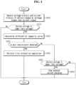
- FIG. 4 is a flowchart exemplarily showing a battery management method according to a first embodiment of the present disclosure
- FIG. 5 is a flowchart exemplarily showing a battery management method according to a second embodiment of the present disclosure.
- the method of FIG. 4 may be repeated at the predetermined time interval until the main feature point P 3 of the differential capacity curve 203 is detected or the voltage of the battery B reaches the upper limit voltage Vu during constant current charging of the battery B.
- the method of FIG. 5 may be repeated at the predetermined time interval until the additional feature point P A of the differential capacity curve 203 is detected, or the voltage of the battery B reaches the upper limit voltage Vu.
- step S400 the control unit 120 records the voltage history and the current history of the battery B based on the voltage signal from the voltage sensor 111 and the current signal from the current sensor 112. That is, the voltage history and the current history are updated at the predetermined time interval.
- step S410 the control unit 120 determines whether the voltage of the battery B reached the lower limit voltage V L of the reference voltage range ⁇ V. When a value of the step S410 is "Yes”, step S420 is performed. When the value of the step S410 is "No”, the method of FIG. 4 may end.
- step S420 the control unit 120 determines the differential capacity curve 203 indicating a correlation between the voltage of the battery B and the differential capacity based on the voltage history and the current history. That is, each time the step S420 is performed, the differential capacity curve 203 may be updated by voltage information and capacity information newly added for a predetermined time.
- step S430 the control unit 120 determines whether the main feature point P 3 of the differential capacity curve 203 was detected. When a value of the step S430 is "Yes”, step S440 is performed. When the value of the step S430 is "No”, step S450 may be performed.
- step S440 the control unit 120 performs the first protection operation.
- the cut-off voltage or the reference current is decreased by the first protection operation.
- the control unit 120 may transmit a first charging current decrease command indicating the decreased reference current to the charging circuit 20.
- the charging circuit 20 may decrease the magnitude of the reference current in response to the first charging current decrease command.
- step S450 the control unit 120 determines whether the voltage of the battery B reached the upper limit voltage Vu of the reference voltage range ⁇ V. When a value of the step S450 is "Yes”, step S460 may be performed. The value of the step S450 being “No” indicates that polarization is too severe to suppress or a failure occurred in the battery management system 100. When the value of the step S450 is "No”, the method of FIG. 4 may end.
- step S460 the control unit 120 stops the constant current charging. That is, the control unit 120 transmits a charging stop command to the charging circuit 20.
- the charging circuit 20 may stop the supply of the reference current in response to the charging stop command. Alternatively or additionally, the control unit 120 may turn off the switch SW.
- step S500 the control unit 120 records the voltage history and the current history of the battery B based on the voltage signal from the voltage sensor 111 and the current signal from the current sensor 112.
- step S510 the control unit 120 determines the differential capacity curve 203 indicating a correlation between the voltage of the battery B and the differential capacity based on the voltage history and the current history.
- step S520 the control unit 120 determines whether the additional feature point P A of the differential capacity curve 203 was detected. When a value of the step S520 is "Yes”, step S530 is performed. When the value of the step S520 is "No”, step S540 may be performed.
- step S530 the control unit 120 performs the second protection operation.
- the reference current may be additionally decreased by the second protection operation.
- the control unit 120 may transmit a second charging current decrease command indicating the additionally decreased reference current to the charging circuit 20.
- the charging circuit 20 may additionally decrease the magnitude of the reference of in response to the second charging current decrease command.
Landscapes
- Engineering & Computer Science (AREA)
- Manufacturing & Machinery (AREA)
- Chemical & Material Sciences (AREA)
- Chemical Kinetics & Catalysis (AREA)
- Electrochemistry (AREA)
- General Chemical & Material Sciences (AREA)
- Power Engineering (AREA)
- Mechanical Engineering (AREA)
- Transportation (AREA)
- Sustainable Energy (AREA)
- Life Sciences & Earth Sciences (AREA)
- Sustainable Development (AREA)
- General Physics & Mathematics (AREA)
- Physics & Mathematics (AREA)
- Microelectronics & Electronic Packaging (AREA)
- Secondary Cells (AREA)
- Charge And Discharge Circuits For Batteries Or The Like (AREA)
- Electric Propulsion And Braking For Vehicles (AREA)
- Protection Of Static Devices (AREA)
Abstract
Description
- The present disclosure relates to battery protection technology.
- The present application claims the benefit of
Korean Patent Application No. 10-2020-0089755 filed on July 20, 2020 - Recently, there has been a rapid increase in the demand for portable electronic products such as laptop computers, video cameras and mobile phones, and with the extensive development of electric vehicles, accumulators for energy storage, robots and satellites, many studies are being made on high performance batteries that can be charged and discharged repeatedly.
- Currently, commercially available batteries include nickel-cadmium batteries, nickel-hydrogen batteries, nickel-zinc batteries, lithium batteries and the like, and among them, lithium batteries have little or no memory effect, and thus they are gaining more attention than nickel-based batteries for their advantages that recharging can be done whenever it is convenient, the self-discharge rate is very low and the energy density is high.
- During charging or discharging of the battery, polarization occurs in the battery, and the polarization causes an overvoltage of the battery. The polarization relies on the resistance components (for example, Ohm resistance, charge transfer resistance, diffusion resistance) that gradually increase as the battery degrades. Accordingly, as the current rate during charging/discharging is higher, as the temperature of the battery is lower, and as the degree of degradation of the battery is higher, the polarization is severer, and as a result, the magnitude of overvoltage occurring in the battery is higher as well known. When the battery is used in a potential polarization state, the battery rapidly degrades.
- The inventors found that phase change reaction occurring during charging of the battery greatly relies on polarization having a positive correlation with overvoltage of the battery.
- The present disclosure is designed to solve the above-described problem, and therefore the present disclosure is directed to providing a battery management system, a battery management method, a battery pack and an electric vehicle, which determines a differential capacity curve over a preset voltage range in which a single phase change reaction occurs during charging of a battery, and determines the polarization level using the feature point detection result with respect to the differential capacity curve.
- The present disclosure is further directed to providing a battery management system, a battery management method, a battery pack and an electric vehicle, which performs different protection operations for the battery using the polarization level determined from the feature point detection result with respect to the differential capacity curve.
- These and other objects and advantages of the present disclosure may be understood by the following description and will be apparent from the embodiments of the present disclosure. In addition, it will be readily understood that the objects and advantages of the present disclosure may be realized by the means set forth in the appended claims and a combination thereof.
- A battery management system according to an aspect of the present disclosure includes a voltage sensor configured to generate a voltage signal indicating a voltage of a battery, a current sensor configured to generate a current signal indicating a current flowing through the battery, and a control unit configured to record a voltage history and a current history of the battery based on the voltage signal and the current signal at a predetermined time interval during constant current charging of the battery. The control unit is configured to determine a differential capacity curve indicating a correlation between the voltage of the battery and a differential capacity in a reference voltage range based on the voltage history and the current history. The control unit is configured to perform a first protection operation for the battery by comparing a first characteristic voltage of a main feature point with a reference voltage when the main feature point is detected from the differential capacity curve.
- The control unit may be configured to determine, as the main feature point, a maximum point detected from the differential capacity curve for the first time during the constant current charging of the battery.
- The first protection operation may include an operation of decreasing a cut-off voltage of the constant current charging by a compensation voltage corresponding to a voltage difference between the first characteristic voltage and the reference voltage. A lower limit of the cut-off voltage may be limited to an upper limit voltage of the reference voltage range.
- The first protection operation may include an operation of decreasing a reference current of the constant current charging by a first compensation current corresponding to a voltage difference between the first characteristic voltage and the reference voltage.
- The control unit may be configured to perform a second protection operation for the battery when an additional feature point having a second characteristic voltage that is larger than the first characteristic voltage is detected from the differential capacity curve.
- The second protection operation may include an operation of additionally decreasing the reference current decreased by the first protection operation.
- The control unit may be configured to stop the constant current charging when a feature point is not detected from the differential capacity curve.
- The control unit may be configured to determine the reference voltage range based on a maximum capacity of the battery.
- A battery pack according to another aspect of the present disclosure includes the battery management system.
- An electric vehicle according to still another aspect of the present disclosure includes the battery pack.
- A battery management method according to yet another aspect of the present disclosure may be performed at a predetermined time interval during constant current charging of a battery. The battery management method includes recording a voltage history and a current history of the battery based on a voltage signal indicating a voltage of the battery and a current signal indicating a current flowing through the battery, determining a differential capacity curve indicating a correlation between the voltage of the battery and a differential capacity in a reference voltage range based on the voltage history and the current history, and performing a first protection operation for the battery by comparing a first characteristic voltage of a main feature point with a reference voltage when the main feature point is detected from the differential capacity curve.
- The battery management method may further include performing a second protection operation for the battery when an additional feature point having a second characteristic voltage that is larger than the first characteristic voltage is detected from the differential capacity curve.
- According to at least one of the embodiments of the present disclosure, after determining a differential capacity curve over a preset voltage range in which a single phase change reaction occurs during charging of a battery, the polarization level may be determined using the feature point detection result with respect to the differential capacity curve.
- Additionally, according to at least one of the embodiments of the present disclosure, different protection operations for the battery are performed using the polarization level determined from the feature point detection result with respect to the differential capacity curve. Accordingly, it is possible to delay the degradation of the battery and improve safety.
- The effects of the present disclosure are not limited to the effects mentioned above, and these and other effects will be clearly understood by those skilled in the art from the appended claims.
- The accompanying drawings illustrate a preferred embodiment of the present disclosure, and together with the detailed description of the present disclosure described below, serve to provide a further understanding of the technical aspects of the present disclosure, and thus the present disclosure should not be construed as being limited to the drawings.
-
FIG. 1 is a diagram exemplarily showing an exemplary configuration of an electric vehicle according to the present disclosure. -
FIG. 2 is a graph showing an exemplary differential capacity curve over a voltage range including a reference voltage range. -
FIG. 3 is a graph showing an exemplary correlation between a maximum capacity of a battery and a reference voltage range. -
FIG. 4 is a flowchart exemplarily showing a battery management method according to a first embodiment of the present disclosure. -
FIG. 5 is a flowchart exemplarily showing a battery management method according to a second embodiment of the present disclosure. - Hereinafter, the preferred embodiments of the present disclosure will be described in detail with reference to the accompanying drawings. Prior to the description, it should be understood that the terms or words used in the specification and the appended claims should not be construed as being limited to general and dictionary meanings, but rather interpreted based on the meanings and concepts corresponding to the technical aspects of the present disclosure on the basis of the principle that the inventor is allowed to define the terms appropriately for the best explanation.
- Therefore, the embodiments described herein and illustrations shown in the drawings are just a most preferred embodiment of the present disclosure, but not intended to fully describe the technical aspects of the present disclosure, so it should be understood that a variety of other equivalents and modifications could have been made thereto at the time that the application was filed.
- The terms including the ordinal number such as "first", "second" and the like, are used to distinguish one element from another among various elements, but not intended to limit the elements by the terms.
- Unless the context clearly indicates otherwise, it will be understood that the term "comprises" when used in this specification, specifies the presence of stated elements, but does not preclude the presence or addition of one or more other elements. Additionally, the term "control unit" refers to a processing unit of at least one function or operation, and this may be implemented by hardware and software either alone or in combination.
- In addition, throughout the specification, it will be further understood that when an element is referred to as being "connected to" another element, it can be directly connected to the other element or intervening elements may be present.
-
FIG. 1 is a diagram exemplarily showing an exemplary configuration of an electric vehicle according to the present disclosure. - Referring to
FIG. 1 , abattery pack 10 is provided to be mountable on an electricity-powered device such as theelectric vehicle 1. Thebattery pack 10 includes a battery B, a switch SW, acharging circuit 20 and abattery management system 100. - A positive terminal and a negative terminal of the battery B are electrically connected to the
battery management system 100. The battery B is a lithium ion battery, and includes a positive electrode, a negative electrode and a separator. The separator is interposed between the positive electrode and the negative electrode to isolate the positive electrode from the negative electrode. A positive electrode active material may include lithium metal composite oxide, for example, LiNi8/10Co1/10Mn1/10O2. A negative electrode active material may include, for example, a carbon-based material (for example, graphite). - When a polarization phenomenon of the battery B is less than a predetermined level, a single phase change reaction of the positive electrode active material or the negative electrode active material occurs in a reference voltage range (for example, 3.6-3.8 V). The capacity of the battery B greatly changes on the basis of the voltage at which the phase change reaction occurs. Accordingly, after a differential capacity curve is obtained over the reference voltage range, the polarization level may be determined based on the feature point detection result with respect to the differential capacity curve. The polarization phenomenon may be simply referred to as 'polarization', and the extent of the polarization phenomenon may be referred to as 'polarization level'. Each feature point of the differential capacity curve may be used as information indicating the voltage at which the phase change reaction occurs.
- The switch SW is installed on a current path connected in series to the battery B for the charge/discharge of the battery B. While the switch SW is turned on, the battery B can be charged and discharged. The switch SW may be a mechanical relay that is turned on/off by the electromagnetic force of a coil or a semiconductor switch such as a Metal Oxide Semiconductor Field Effect transistor (MOSFET). While the switch SW is turned off, the charge/discharge of the battery B is stopped. The switch SW may be turned on in response to a first switching signal (for example, a high level voltage). The switch SW may be turned off in response to a second switching signal (for example, a low level voltage).
- The charging
circuit 20 is electrically connected to the current path for the charge/discharge of the battery B. The chargingcircuit 20 is configured to convert the alternating current power from an external device (for example, a commercial power source) to the direct current power. The chargingcircuit 20 may include a constant current circuit to adjust a current rate (referred to as 'C-rate') for constant current charging according to a command from thebattery management system 100. - The
battery management system 100 is provided to protect the battery B from over-polarization. Thebattery management system 100 includes asensing unit 110, acontrol unit 120 and amemory unit 130. Thebattery management system 100 may further include aninterface unit 140. Thebattery management system 100 may further include aswitch driver 150. - The
sensing unit 110 includes a voltage sensor 111 and acurrent sensor 112. The voltage sensor 111 is connected in parallel to the battery B, and is configured to detect a voltage across the battery B and generate a voltage signal indicating the detected voltage. Thecurrent sensor 112 is connected in series to the battery B through the current path. Thecurrent sensor 112 is configured to detect a current flowing through the battery B, and generate a current signal indicating the detected current. Thecontrol unit 120 may collect sensing information including the voltage signal and the current signal in synchronization from thesensing unit 110. - The
control unit 120 may be implemented in hardware using at least one of application specific integrated circuits (ASICs), digital signal processors (DSPs), digital signal processing devices (DSPDs), programmable logic devices (PLDs), field programmable gate arrays (FPGAs), microprocessors or electrical units for performing the other functions. - The
control unit 120 is operably coupled to the chargingcircuit 20 and thesensing unit 110. The operably coupled refers to direct/indirect connection to enable signal transmission and reception in one or two directions. Thecontrol unit 120 is configured to perform an operation for protecting the battery B as described below. - When the voltage of the battery B is less than a lower limit voltage of the reference voltage range, the
control unit 120 may transmit a charging start command to the chargingcircuit 20. The charging start command includes information indicating a current rate of a reference current. The chargingcircuit 20 performs constant current charging of the battery B with the reference current in response to the charging start command. - The
control unit 120 is configured to determine the voltage, current, capacity and State-Of-Charge (SOC) of the battery B at a predetermined time interval based on the voltage signal and the current signal included in the sensing information at the predetermined time interval during constant current charging of the battery B. The SOC may be determined by at least one of a variety of well-known algorithms (for example, an ampere-hour integral method, a Kalman filtering method), and its detailed description is omitted. - The capacity of the battery B indicates the amount of electric charge stored in the battery B and may be referred to as 'residual capacity', and may be determined by current integration of the battery B at the predetermined time interval. The SOC of the battery B indicates a ratio of the capacity of the battery B to the maximum capacity (referred to as 'full charge capacity') of the battery B, and in general, it is indicated as 0-1 or 0-100%. The maximum capacity of the battery B gradually decreases as the battery B degrades.
- A voltage history, a current history and a capacity history corresponding respectively to the voltage, current and capacity obtained at the predetermined time interval during constant current charging may be recorded in the
memory unit 130 by thecontrol unit 120. The capacity history is based on the current history. A history of a certain parameter refers to a time-series change of the corresponding parameter over a period of time. - The
memory unit 130 is operably coupled to thecontrol unit 120. Thememory unit 130 may be also operably coupled to thesensing unit 110. Thememory unit 130 may include, for example, at least one type of storage medium of flash memory type, hard disk type, Solid State Disk (SSD) type, Silicon Disk Drive (SDD) type, multimedia card micro type, random access memory (RAM), static random access memory (SRAM), read-only memory (ROM), electrically erasable programmable read-only memory (EEPROM) or programmable read-only memory (PROM). - The
memory unit 130 may store data and programs required for a computation operation by thecontrol unit 120. Thememory unit 130 may store data indicating the result of the computation operation by thecontrol unit 120. - The
interface unit 140 is configured to support wired or wireless communication between thecontrol unit 120 and a high-level controller 2 (for example, ECU: Electronic Control Unit) of theelectric vehicle 1. The wired communication may be, for example, controller area network (CAN) communication, and the wireless communication may be, for example, Zigbee or Bluetooth communication. The communication protocol is not limited to a particular type and may include any communication protocol that supports wired/wireless communication between thecontrol unit 120 and the high-level controller 2. Theinterface unit 140 may include an output device (for example, a display, a speaker) to provide the information received from thecontrol unit 120 and/or the high-level controller 2 in a recognizable format. - The
switch driver 150 is electrically coupled to thecontrol unit 120 and the switch SW. Theswitch driver 150 is configured to selectively output the first or second switching signal to the switch SW in response to the command from thecontrol unit 120. Thecontrol unit 120 may command theswitch driver 150 to turn on the switch SW during constant current charging of the battery B. -
FIG. 2 is a graph showing an exemplary differential capacity curve over the voltage range including the reference voltage range, andFIG. 3 is a graph showing an exemplary correlation between the maximum capacity of the battery and the reference voltage range. - Through experiments in which the polarization level is forced to increase during constant current charging, the inventors recognized the following fact. First, as the polarization level increases, the voltage at which the phase change reaction occurs gradually increases (i.e., shifted to higher voltage). Second, when the polarization level is increased more, the phase change reaction gradually occurs over a wide voltage range or the phase change reaction is split into separated voltage ranges.
- In the specification, the differential capacity curve may refer to a dataset that records a correlation between the voltage of the battery B and a differential capacity. The differential capacity refers to a ratio dQ/dV of a capacity change dQ of the battery B to a voltage change dV of the battery B at the predetermined time interval.
- In
FIG. 2 , VL and Vu indicate the lower and upper limit voltages of the reference voltage range ΔV, respectively, and VE indicates the cut-off voltage of constant current charging. Referring toFIG. 2 , afirst curve 201 indicates the differential capacity curve of the battery B free of polarization, a second curve 202 indicates the differential capacity curve when the polarization level of the battery B is less than the predetermined level, and athird curve 203 indicates the differential capacity curve when the polarization level of the battery B is equal to or larger than the predetermined level. In each of thecurves FIG. 2 , the maximum point appearing in the reference voltage range ΔV for the first time in each of thecurves - The
control unit 120 may detect the feature point appearing in the differential capacity curve at the predetermined time interval even before the voltage of the battery B reaches the upper limit voltage Vu during constant current charging. Alternatively, thecontrol unit 120 may simultaneously detect all the feature points appearing in the differential capacity curve over the reference voltage range ΔV after the voltage of the battery B reaches the upper limit voltage Vu. - Describing the
first curve 201, there is a single feature point P1 in the reference voltage range ΔV. Thememory unit 130 may pre-store the dataset corresponding to thefirst curve 201. Thecontrol unit 120 may set a reference voltage for determining the polarization level occurred in the battery B to be equal to a characteristic voltage V1 of the feature point P1. - Describing the second curve 202, there is a single feature point P2 in the reference voltage range ΔV. It can be seen that a feature point P2 is shifted to higher voltage from the feature point P1. That is, a characteristic voltage V2 of the feature point P2 is higher than the characteristic voltage V1 of the feature point P1, and a voltage difference between the characteristic voltage V2 and the characteristic voltage V1 have a positive correlation with the polarization level occurred during constant current charging during which the second curve 202 is obtained.
- The
control unit 120 may perform a first protection operation based on the voltage difference between the characteristic voltage V2 and the characteristic voltage V1. Thecontrol unit 120 may perform the first protection operation from the time point at which the feature point P2 is detected. - The first protection operation may include an operation of decreasing the cut-off voltage of constant current charging by a compensation voltage corresponding to the voltage difference. The
control unit 120 may determine the compensation voltage to be equal to the product of multiplying the voltage difference by a predetermined first weight. Where the voltage difference = V2 - V1 = 0.1 [V] and the first weight=0.9, VE = 4.0 [V], the compensation voltage = 0.09 [V], and the decreased cut-off voltage = VE - 0.09 [V] = 3.91 [V] = VE'. Thecontrol unit 120 may set the decreased cut-off voltage VE' as the cut-off voltage of constant current charging. - The first protection operation may include an operation of decreasing the reference current by the compensation current corresponding to the voltage difference. The
control unit 120 may determine the compensation current to be equal to the product of multiplying the voltage difference by a predetermined second weight. Assume that the voltage difference = V2 - V1 = 0.1 [V], the second weight =0.5 [C-rate/V] and the reference current = 0.50 [C-rate], the compensation current = 0.05 [C-rate], the decreased reference current = 0.50 - 0.05 [C-rate] = 0.45 [C-rate]. Thecontrol unit 120 may set the decreased reference current as the reference current of constant current charging. - Describing the
third curve 203, there are two feature points P3, PA in the reference voltage range ΔV. It can be seen that a feature point P3 is shifted to higher voltage from the feature point P1 than the feature point P2. That is, a characteristic voltage V3 of the feature point P3 is higher than the characteristic voltage V2 of the feature point P2, and a voltage difference between the characteristic voltage V3 and the characteristic voltage V1 indicates the polarization level occurred during constant current charging during which thethird curve 203 is obtained. - The
control unit 120 may perform the first protection operation based on the voltage difference between the characteristic voltage V3 and the characteristic voltage V1. The description of the first protection operation is in common with the description made with respect to the second curve 202. That is, thecontrol unit 120 may decrease the cut-off voltage and/or the reference current as the first protection operation. - Assume that the
third curve 203 is obtained after the second curve 202 is obtained. In the decrease of the cut-off voltage, the voltage difference = V3 - V1 = 0.12 [V], the first weight=0.9, VE' = 3.91 [V], the compensation voltage = 0.108 [V], the decreased cut-off voltage = VE' - 0.108 [V] = 3.802 [V] = VE". Thecontrol unit 120 may set the decreased cut-off voltage VE" as the cut-off voltage of constant current charging. The lower limit of the cut-off voltage may be limited to the upper limit voltage Vu. In the decrease of the reference current, where the voltage difference = V3 - V1 = 0.12 [V], the second weight = 0.5 [C-rate/V], the reference current = 0.45 [C-rate], the compensation current = 0.06 [C-rate], the decreased reference current = 0.45 - 0.06 [C-rate] = 0.39 [C-rate]. Thecontrol unit 120 may set the decreased reference current as the reference current of constant current charging. - The
control unit 120 may monitor whether an additional feature point appears between the characteristic voltage V3 and the upper limit voltage Vu at the predetermined time interval after the feature point P3 is detected. Thecontrol unit 120 may detect a point at which the slope of thethird curve 203 is equal to or larger than a predetermined threshold or the minimum point of thethird curve 203 as the additional feature point. - In
FIG. 2 , the minimum point PA appearing between the characteristic voltage V3 and the upper limit voltage Vu for the first time is shown as being detected as the additional feature point. The additional feature point PA has a characteristic voltage VA between the characteristic voltage V3 and the upper limit voltage Vu. - When the additional feature point PA is detected, the
control unit 120 may perform a second protection operation. Thecontrol unit 120 may perform the second protection operation from the time point at which the additional feature point PA is detected. - The second protection operation may include an operation of additionally decreasing the reference current. Assume that the additional feature point PA is detected after the reference current is decreased from 0.45 [C-rate] to 0.39 [C-rate] by the first protection operation. In this case, the
control unit 120 may set 0.351 [C-rate] obtained by multiplying the reference current 0.39 [C-rate] by a third weight (for example, 0.9) as the reference current of constant current charging. - The lower limit voltage VL and the upper limit voltage Vu may be preset fixed values. Alternatively, the
control unit 120 may determine the lower limit voltage VL and the upper limit voltage Vu of the reference voltage range ΔV based on the maximum capacity QMAX of the battery B at the start of constant current charging. The maximum capacity QMAX may be determined as at least one of a variety of well-known algorithms, and its detailed description is omitted. - A relationship between the degree of degradation and the phase change reaction of the battery B is similar to a relationship between polarization and phase change reaction. Accordingly, to detect polarization occurred in the battery B from the differential voltage curve more accurately, it may be advantageous to determine the reference voltage range ΔV based on the maximum capacity corresponding to the degree of degradation of the battery B. Referring to
FIG. 3 , acurve 301 indicates a relationship between the maximum capacity and the lower limit voltage, and acurve 302 indicates a relationship between the maximum capacity and the upper limit voltage. The twocurves FIG. 3 may be prepared based on the results of experiment conducted on batteries manufactured with the same electrical and chemical performance as the battery B. Thememory unit 130 may pre-store the dataset (for example, a lookup table) corresponding to the twocurves control unit 120 may set VX and VY associated with QMAX as a voltage VL and the upper limit voltage Vu, respectively. -
FIG. 4 is a flowchart exemplarily showing a battery management method according to a first embodiment of the present disclosure, andFIG. 5 is a flowchart exemplarily showing a battery management method according to a second embodiment of the present disclosure. For convenience of description, the methods ofFIGS. 4 and5 will be described on the basis of thethird curve 203. The method ofFIG. 4 may be repeated at the predetermined time interval until the main feature point P3 of thedifferential capacity curve 203 is detected or the voltage of the battery B reaches the upper limit voltage Vu during constant current charging of the battery B. On the condition that the main feature point P3 is detected by the method ofFIG. 4 , the method ofFIG. 5 may be repeated at the predetermined time interval until the additional feature point PA of thedifferential capacity curve 203 is detected, or the voltage of the battery B reaches the upper limit voltage Vu. - Referring to
FIGS. 1 to 4 , in step S400, thecontrol unit 120 records the voltage history and the current history of the battery B based on the voltage signal from the voltage sensor 111 and the current signal from thecurrent sensor 112. That is, the voltage history and the current history are updated at the predetermined time interval. - In step S410, the
control unit 120 determines whether the voltage of the battery B reached the lower limit voltage VL of the reference voltage range ΔV. When a value of the step S410 is "Yes", step S420 is performed. When the value of the step S410 is "No", the method ofFIG. 4 may end. - In step S420, the
control unit 120 determines thedifferential capacity curve 203 indicating a correlation between the voltage of the battery B and the differential capacity based on the voltage history and the current history. That is, each time the step S420 is performed, thedifferential capacity curve 203 may be updated by voltage information and capacity information newly added for a predetermined time. - In step S430, the
control unit 120 determines whether the main feature point P3 of thedifferential capacity curve 203 was detected. When a value of the step S430 is "Yes", step S440 is performed. When the value of the step S430 is "No", step S450 may be performed. - In step S440, the
control unit 120 performs the first protection operation. The cut-off voltage or the reference current is decreased by the first protection operation. Thecontrol unit 120 may transmit a first charging current decrease command indicating the decreased reference current to the chargingcircuit 20. The chargingcircuit 20 may decrease the magnitude of the reference current in response to the first charging current decrease command. - In step S450, the
control unit 120 determines whether the voltage of the battery B reached the upper limit voltage Vu of the reference voltage range ΔV. When a value of the step S450 is "Yes", step S460 may be performed. The value of the step S450 being "No" indicates that polarization is too severe to suppress or a failure occurred in thebattery management system 100. When the value of the step S450 is "No", the method ofFIG. 4 may end. - In step S460, the
control unit 120 stops the constant current charging. That is, thecontrol unit 120 transmits a charging stop command to the chargingcircuit 20. The chargingcircuit 20 may stop the supply of the reference current in response to the charging stop command. Alternatively or additionally, thecontrol unit 120 may turn off the switch SW. - Referring to
FIG. 5 , in step S500, thecontrol unit 120 records the voltage history and the current history of the battery B based on the voltage signal from the voltage sensor 111 and the current signal from thecurrent sensor 112. - In step S510, the
control unit 120 determines thedifferential capacity curve 203 indicating a correlation between the voltage of the battery B and the differential capacity based on the voltage history and the current history. - In step S520, the
control unit 120 determines whether the additional feature point PA of thedifferential capacity curve 203 was detected. When a value of the step S520 is "Yes", step S530 is performed. When the value of the step S520 is "No", step S540 may be performed. - In step S530, the
control unit 120 performs the second protection operation. The reference current may be additionally decreased by the second protection operation. Thecontrol unit 120 may transmit a second charging current decrease command indicating the additionally decreased reference current to the chargingcircuit 20. The chargingcircuit 20 may additionally decrease the magnitude of the reference of in response to the second charging current decrease command. - The embodiments of the present disclosure described hereinabove are not implemented only through the apparatus and method, and may be implemented through programs that perform functions corresponding to the configurations of the embodiments of the present disclosure or recording media having the programs recorded thereon, and such implementation may be easily achieved by those skilled in the art from the disclosure of the embodiments previously described.
- While the present disclosure has been hereinabove described with regard to a limited number of embodiments and drawings, the present disclosure is not limited thereto and it is obvious to those skilled in the art that various modifications and changes may be made thereto within the technical aspects of the present disclosure and the equivalent scope of the appended claims.
- Additionally, as many substitutions, modifications and changes may be made to the present disclosure described hereinabove by those skilled in the art without departing from the technical aspects of the present disclosure, the present disclosure is not limited by the above-described embodiments and the accompanying drawings, and some or all of the embodiments may be selectively combined to allow various modifications.
Claims (12)
- A battery management system, comprising:a voltage sensor configured to generate a voltage signal indicating a voltage of a battery;a current sensor configured to generate a current signal indicating a current flowing through the battery; anda control unit configured to record a voltage history and a current history of the battery based on the voltage signal and the current signal at a predetermined time interval during constant current charging of the battery,wherein the control unit is configured to:determine a differential capacity curve indicating a correlation between the voltage of the battery and a differential capacity in a reference voltage range based on the voltage history and the current history, andperform a first protection operation for the battery by comparing a first characteristic voltage of a main feature point with a reference voltage when the main feature point is detected from the differential capacity curve.
- The battery management system according to claim 1, wherein the control unit is configured to determine, as the main feature point, a maximum point detected from the differential capacity curve for the first time during the constant current charging of the battery.
- The battery management system according to claim 1, wherein the first protection operation includes an operation of decreasing a cut-off voltage of the constant current charging by a compensation voltage corresponding to a voltage difference between the first characteristic voltage and the reference voltage, and
a lower limit of the cut-off voltage is limited to an upper limit voltage of the reference voltage range. - The battery management system according to claim 1, wherein the first protection operation includes an operation of decreasing a reference current of the constant current charging by a first compensation current corresponding to a voltage difference between the first characteristic voltage and the reference voltage.
- The battery management system according to claim 4, wherein the control unit is configured to perform a second protection operation for the battery when an additional feature point having a second characteristic voltage that is larger than the first characteristic voltage is detected from the differential capacity curve.
- The battery management system according to claim 5, wherein the second protection operation includes an operation of additionally decreasing the reference current decreased by the first protection operation.
- The battery management system according to claim 1, wherein the control unit is configured to stop the constant current charging when a feature point is not detected from the differential capacity curve.
- The battery management system according to claim 1, wherein the control unit is configured to determine the reference voltage range based on a maximum capacity of the battery.
- A battery pack comprising the battery management system according to any one of claims 1 to 8.
- An electric vehicle comprising the battery pack according to claim 9.
- A battery management method performed at a predetermined time interval during constant current charging of a battery, the battery management method comprising:recording a voltage history and a current history of the battery based on a voltage signal indicating a voltage of the battery and a current signal indicating a current flowing through the battery;determining a differential capacity curve indicating a correlation between the voltage of the battery and a differential capacity in a reference voltage range based on the voltage history and the current history; andperforming a first protection operation for the battery by comparing a first characteristic voltage of a main feature point with a reference voltage when the main feature point is detected from the differential capacity curve.
- The battery management method according to claim 11, further comprising:
performing a second protection operation for the battery when an additional feature point having a second characteristic voltage that is larger than the first characteristic voltage is detected from the differential capacity curve.
Applications Claiming Priority (2)
| Application Number | Priority Date | Filing Date | Title |
|---|---|---|---|
| KR1020200089755A KR102737635B1 (en) | 2020-07-20 | 2020-07-20 | Battery management system, battery management method, battery pack, and electric vehicle |
| PCT/KR2021/009285 WO2022019595A1 (en) | 2020-07-20 | 2021-07-19 | Battery management system, battery management method, battery pack, and electric vehicle |
Publications (3)
| Publication Number | Publication Date |
|---|---|
| EP4156376A1 true EP4156376A1 (en) | 2023-03-29 |
| EP4156376A4 EP4156376A4 (en) | 2024-02-07 |
| EP4156376B1 EP4156376B1 (en) | 2025-07-16 |
Family
ID=79729292
Family Applications (1)
| Application Number | Title | Priority Date | Filing Date |
|---|---|---|---|
| EP21847191.0A Active EP4156376B1 (en) | 2020-07-20 | 2021-07-19 | Battery management system, battery management method, battery pack and electric vehicle |
Country Status (9)
| Country | Link |
|---|---|
| US (1) | US12308689B2 (en) |
| EP (1) | EP4156376B1 (en) |
| JP (1) | JP7331327B2 (en) |
| KR (1) | KR102737635B1 (en) |
| CN (1) | CN114846674B (en) |
| ES (1) | ES3048464T3 (en) |
| HU (1) | HUE073189T2 (en) |
| PL (1) | PL4156376T3 (en) |
| WO (1) | WO2022019595A1 (en) |
Families Citing this family (5)
| Publication number | Priority date | Publication date | Assignee | Title |
|---|---|---|---|---|
| EP4145588B1 (en) * | 2020-08-13 | 2025-03-05 | LG Energy Solution, Ltd. | Battery management system, battery management method, battery pack, and electric vehicle |
| TWI822063B (en) * | 2022-05-31 | 2023-11-11 | 中興電工機械股份有限公司 | Charging and discharging mechanism of fuel cell system to secondary battery |
| TWI832652B (en) * | 2022-12-30 | 2024-02-11 | 致茂電子股份有限公司 | Source measure device |
| CN116520159B (en) * | 2023-04-10 | 2025-02-11 | 岚图汽车科技有限公司 | Method and electronic device for determining charging cut-off voltage of lithium-ion battery |
| CN120600957B (en) * | 2025-08-06 | 2025-10-21 | 易德维能源科技(上海)有限公司 | Power supply and energy storage system |
Family Cites Families (19)
| Publication number | Priority date | Publication date | Assignee | Title |
|---|---|---|---|---|
| EP2096452A1 (en) | 2007-12-13 | 2009-09-02 | Panasonic Corporation | Lifetime estimating method and deterioration suppressing method for lithium secondary cell, lifetime estimator and deterioration suppressor, battery pack using the same, and charger |
| US9046586B2 (en) | 2010-03-29 | 2015-06-02 | Panasonic Intellectual Property Management Co., Ltd. | Method and device for diagnosing secondary battery degradation |
| JP5741348B2 (en) | 2011-09-21 | 2015-07-01 | トヨタ自動車株式会社 | Secondary battery system and vehicle |
| JP5372208B2 (en) | 2012-05-11 | 2013-12-18 | 株式会社Wave Technology | Secondary battery charging method and charging device using the same |
| KR101494156B1 (en) | 2012-06-07 | 2015-02-23 | 주식회사 엘지화학 | Charging Method of Secondary Battery |
| WO2015080285A1 (en) * | 2013-11-29 | 2015-06-04 | 日立オートモティブシステムズ株式会社 | Battery module and assembled battery |
| JP6299623B2 (en) * | 2015-02-10 | 2018-03-28 | トヨタ自動車株式会社 | Initial charging method for lithium-ion battery |
| JP6500789B2 (en) | 2016-01-19 | 2019-04-17 | トヨタ自動車株式会社 | Control system of secondary battery |
| JP6380417B2 (en) * | 2016-01-21 | 2018-08-29 | 横河電機株式会社 | Secondary battery capacity measuring system and secondary battery capacity measuring method |
| KR102813037B1 (en) | 2017-01-23 | 2025-05-27 | 삼성에스디아이 주식회사 | Charging method of battery and battery charging system |
| JP6978723B2 (en) * | 2017-06-05 | 2021-12-08 | 三菱自動車工業株式会社 | Rechargeable battery system |
| JP2019056595A (en) * | 2017-09-20 | 2019-04-11 | 三菱自動車工業株式会社 | Secondary battery system |
| TWI657639B (en) * | 2017-12-04 | 2019-04-21 | Industrial Technology Research Institute | Battery discharge process determination method and system |
| KR102633738B1 (en) | 2017-12-08 | 2024-02-06 | 웨스팅하우스 일렉트릭 컴퍼니 엘엘씨 | Detection devices usable in nuclear reactors, and associated methods |
| JP7141012B2 (en) | 2018-03-13 | 2022-09-22 | 三菱自動車工業株式会社 | Secondary battery system |
| KR102349300B1 (en) | 2018-04-10 | 2022-01-10 | 주식회사 엘지에너지솔루션 | Apparatus, method, battery pack and electrical system for determining electrode information of battery |
| KR102660349B1 (en) * | 2018-12-11 | 2024-04-24 | 현대자동차주식회사 | System and method for charging battery |
| KR102659679B1 (en) * | 2019-04-22 | 2024-04-19 | 주식회사 엘지에너지솔루션 | Apparatus and method for determining differential voltage curve of battery, and battery pack including the apparatus |
| KR102766401B1 (en) * | 2019-09-19 | 2025-02-10 | 주식회사 엘지에너지솔루션 | Battery management apparatus, battery management method, battery pack and electric vehicle |
-
2020
- 2020-07-20 KR KR1020200089755A patent/KR102737635B1/en active Active
-
2021
- 2021-07-19 ES ES21847191T patent/ES3048464T3/en active Active
- 2021-07-19 CN CN202180007359.XA patent/CN114846674B/en active Active
- 2021-07-19 HU HUE21847191A patent/HUE073189T2/en unknown
- 2021-07-19 US US17/783,066 patent/US12308689B2/en active Active
- 2021-07-19 PL PL21847191.0T patent/PL4156376T3/en unknown
- 2021-07-19 EP EP21847191.0A patent/EP4156376B1/en active Active
- 2021-07-19 WO PCT/KR2021/009285 patent/WO2022019595A1/en not_active Ceased
- 2021-07-19 JP JP2022529455A patent/JP7331327B2/en active Active
Also Published As
| Publication number | Publication date |
|---|---|
| ES3048464T3 (en) | 2025-12-10 |
| JP2023503080A (en) | 2023-01-26 |
| HUE073189T2 (en) | 2026-01-28 |
| EP4156376A4 (en) | 2024-02-07 |
| EP4156376B1 (en) | 2025-07-16 |
| US20230035092A1 (en) | 2023-02-02 |
| US12308689B2 (en) | 2025-05-20 |
| JP7331327B2 (en) | 2023-08-23 |
| PL4156376T3 (en) | 2025-11-24 |
| CN114846674B (en) | 2025-09-23 |
| CN114846674A (en) | 2022-08-02 |
| KR20220010961A (en) | 2022-01-27 |
| KR102737635B1 (en) | 2024-12-02 |
| WO2022019595A1 (en) | 2022-01-27 |
Similar Documents
| Publication | Publication Date | Title |
|---|---|---|
| US12498426B2 (en) | Apparatus and method for determining degradation degree of battery and battery pack comprising the apparatus | |
| EP3982141B1 (en) | Battery management apparatus, battery management method, battery pack and electric vehicle | |
| EP4053573A1 (en) | Battery management system, battery pack, and electronic vehicle and battery management method | |
| EP4156376B1 (en) | Battery management system, battery management method, battery pack and electric vehicle | |
| EP3835802B1 (en) | Apparatus and method for determining degradation state of battery, battery pack and electric vehicle | |
| EP4167344A1 (en) | Battery management system, battery management method, battery pack and electric vehicle | |
| US12322766B2 (en) | Battery management system, battery pack, electric vehicle and battery management method | |
| EP4068562A1 (en) | Battery management system, battery management method, battery pack, and electric vehicle | |
| KR102913999B1 (en) | Battery management system, battery management method, battery pack, and electric vehicle | |
| EP4180826A1 (en) | Battery diagnosis device, battery diagnosis method, battery pack and electric vehicle | |
| US12344120B2 (en) | Battery management system, battery management method, battery pack, and electric vehicle | |
| US20260048680A1 (en) | Battery Management System, Battery Management Method, Battery Pack, and Electric Vehicle |
Legal Events
| Date | Code | Title | Description |
|---|---|---|---|
| STAA | Information on the status of an ep patent application or granted ep patent |
Free format text: STATUS: THE INTERNATIONAL PUBLICATION HAS BEEN MADE |
|
| PUAI | Public reference made under article 153(3) epc to a published international application that has entered the european phase |
Free format text: ORIGINAL CODE: 0009012 |
|
| STAA | Information on the status of an ep patent application or granted ep patent |
Free format text: STATUS: REQUEST FOR EXAMINATION WAS MADE |
|
| 17P | Request for examination filed |
Effective date: 20220616 |
|
| AK | Designated contracting states |
Kind code of ref document: A1 Designated state(s): AL AT BE BG CH CY CZ DE DK EE ES FI FR GB GR HR HU IE IS IT LI LT LU LV MC MK MT NL NO PL PT RO RS SE SI SK SM TR |
|
| DAV | Request for validation of the european patent (deleted) | ||
| DAX | Request for extension of the european patent (deleted) | ||
| A4 | Supplementary search report drawn up and despatched |
Effective date: 20240109 |
|
| RIC1 | Information provided on ipc code assigned before grant |
Ipc: B60L 58/10 20190101ALI20240103BHEP Ipc: G01R 31/36 20200101ALI20240103BHEP Ipc: H01M 10/44 20060101ALI20240103BHEP Ipc: H01M 10/42 20060101ALI20240103BHEP Ipc: H01M 10/48 20060101AFI20240103BHEP |
|
| GRAP | Despatch of communication of intention to grant a patent |
Free format text: ORIGINAL CODE: EPIDOSNIGR1 |
|
| STAA | Information on the status of an ep patent application or granted ep patent |
Free format text: STATUS: GRANT OF PATENT IS INTENDED |
|
| INTG | Intention to grant announced |
Effective date: 20250422 |
|
| GRAS | Grant fee paid |
Free format text: ORIGINAL CODE: EPIDOSNIGR3 |
|
| GRAA | (expected) grant |
Free format text: ORIGINAL CODE: 0009210 |
|
| STAA | Information on the status of an ep patent application or granted ep patent |
Free format text: STATUS: THE PATENT HAS BEEN GRANTED |
|
| P01 | Opt-out of the competence of the unified patent court (upc) registered |
Free format text: CASE NUMBER: APP_24665/2025 Effective date: 20250523 |
|
| AK | Designated contracting states |
Kind code of ref document: B1 Designated state(s): AL AT BE BG CH CY CZ DE DK EE ES FI FR GB GR HR HU IE IS IT LI LT LU LV MC MK MT NL NO PL PT RO RS SE SI SK SM TR |
|
| REG | Reference to a national code |
Ref country code: GB Ref legal event code: FG4D |
|
| REG | Reference to a national code |
Ref country code: CH Ref legal event code: EP |
|
| REG | Reference to a national code |
Ref country code: DE Ref legal event code: R096 Ref document number: 602021034352 Country of ref document: DE |
|
| REG | Reference to a national code |
Ref country code: IE Ref legal event code: FG4D |
|
| PGFP | Annual fee paid to national office [announced via postgrant information from national office to epo] |
Ref country code: NL Payment date: 20250722 Year of fee payment: 5 |
|
| REG | Reference to a national code |
Ref country code: NL Ref legal event code: FP |
|
| PGFP | Annual fee paid to national office [announced via postgrant information from national office to epo] |
Ref country code: ES Payment date: 20250822 Year of fee payment: 5 |
|
| PGFP | Annual fee paid to national office [announced via postgrant information from national office to epo] |
Ref country code: DE Payment date: 20250721 Year of fee payment: 5 |
|
| REG | Reference to a national code |
Ref country code: SE Ref legal event code: TRGR |
|
| PGFP | Annual fee paid to national office [announced via postgrant information from national office to epo] |
Ref country code: BE Payment date: 20250722 Year of fee payment: 5 Ref country code: GB Payment date: 20250722 Year of fee payment: 5 |
|
| PGFP | Annual fee paid to national office [announced via postgrant information from national office to epo] |
Ref country code: FR Payment date: 20250725 Year of fee payment: 5 Ref country code: AT Payment date: 20251020 Year of fee payment: 5 |
|
| PGFP | Annual fee paid to national office [announced via postgrant information from national office to epo] |
Ref country code: SE Payment date: 20250722 Year of fee payment: 5 |
|
| PG25 | Lapsed in a contracting state [announced via postgrant information from national office to epo] |
Ref country code: PT Free format text: LAPSE BECAUSE OF FAILURE TO SUBMIT A TRANSLATION OF THE DESCRIPTION OR TO PAY THE FEE WITHIN THE PRESCRIBED TIME-LIMIT Effective date: 20251117 |
|
| REG | Reference to a national code |
Ref country code: ES Ref legal event code: FG2A Ref document number: 3048464 Country of ref document: ES Kind code of ref document: T3 Effective date: 20251210 |
|
| PGFP | Annual fee paid to national office [announced via postgrant information from national office to epo] |
Ref country code: HU Payment date: 20251127 Year of fee payment: 5 |
|
| REG | Reference to a national code |
Ref country code: AT Ref legal event code: MK05 Ref document number: 1814936 Country of ref document: AT Kind code of ref document: T Effective date: 20250716 |
|
| PG25 | Lapsed in a contracting state [announced via postgrant information from national office to epo] |
Ref country code: IS Free format text: LAPSE BECAUSE OF FAILURE TO SUBMIT A TRANSLATION OF THE DESCRIPTION OR TO PAY THE FEE WITHIN THE PRESCRIBED TIME-LIMIT Effective date: 20251116 |
|
| PG25 | Lapsed in a contracting state [announced via postgrant information from national office to epo] |
Ref country code: NO Free format text: LAPSE BECAUSE OF FAILURE TO SUBMIT A TRANSLATION OF THE DESCRIPTION OR TO PAY THE FEE WITHIN THE PRESCRIBED TIME-LIMIT Effective date: 20251016 |
|
| REG | Reference to a national code |
Ref country code: LT Ref legal event code: MG9D |
|
| PG25 | Lapsed in a contracting state [announced via postgrant information from national office to epo] |
Ref country code: AT Free format text: LAPSE BECAUSE OF FAILURE TO SUBMIT A TRANSLATION OF THE DESCRIPTION OR TO PAY THE FEE WITHIN THE PRESCRIBED TIME-LIMIT Effective date: 20250716 |
|
| PG25 | Lapsed in a contracting state [announced via postgrant information from national office to epo] |
Ref country code: FI Free format text: LAPSE BECAUSE OF FAILURE TO SUBMIT A TRANSLATION OF THE DESCRIPTION OR TO PAY THE FEE WITHIN THE PRESCRIBED TIME-LIMIT Effective date: 20250716 |
|
| PGFP | Annual fee paid to national office [announced via postgrant information from national office to epo] |
Ref country code: IT Payment date: 20250722 Year of fee payment: 5 |
|
| PG25 | Lapsed in a contracting state [announced via postgrant information from national office to epo] |
Ref country code: HR Free format text: LAPSE BECAUSE OF FAILURE TO SUBMIT A TRANSLATION OF THE DESCRIPTION OR TO PAY THE FEE WITHIN THE PRESCRIBED TIME-LIMIT Effective date: 20250716 |
|
| PG25 | Lapsed in a contracting state [announced via postgrant information from national office to epo] |
Ref country code: GR Free format text: LAPSE BECAUSE OF FAILURE TO SUBMIT A TRANSLATION OF THE DESCRIPTION OR TO PAY THE FEE WITHIN THE PRESCRIBED TIME-LIMIT Effective date: 20251017 |
|
| PGFP | Annual fee paid to national office [announced via postgrant information from national office to epo] |
Ref country code: TR Payment date: 20251009 Year of fee payment: 5 |
|
| PG25 | Lapsed in a contracting state [announced via postgrant information from national office to epo] |
Ref country code: LV Free format text: LAPSE BECAUSE OF FAILURE TO SUBMIT A TRANSLATION OF THE DESCRIPTION OR TO PAY THE FEE WITHIN THE PRESCRIBED TIME-LIMIT Effective date: 20250716 |
|
| PG25 | Lapsed in a contracting state [announced via postgrant information from national office to epo] |
Ref country code: BG Free format text: LAPSE BECAUSE OF FAILURE TO SUBMIT A TRANSLATION OF THE DESCRIPTION OR TO PAY THE FEE WITHIN THE PRESCRIBED TIME-LIMIT Effective date: 20250716 |
|
| PGFP | Annual fee paid to national office [announced via postgrant information from national office to epo] |
Ref country code: PL Payment date: 20250715 Year of fee payment: 5 |
|
| PG25 | Lapsed in a contracting state [announced via postgrant information from national office to epo] |
Ref country code: RS Free format text: LAPSE BECAUSE OF FAILURE TO SUBMIT A TRANSLATION OF THE DESCRIPTION OR TO PAY THE FEE WITHIN THE PRESCRIBED TIME-LIMIT Effective date: 20251016 |
|
| REG | Reference to a national code |
Ref country code: HU Ref legal event code: AG4A Ref document number: E073189 Country of ref document: HU |
|
| REG | Reference to a national code |
Ref country code: CH Ref legal event code: H13 Free format text: ST27 STATUS EVENT CODE: U-0-0-H10-H13 (AS PROVIDED BY THE NATIONAL OFFICE) Effective date: 20260224 |
|
| PG25 | Lapsed in a contracting state [announced via postgrant information from national office to epo] |
Ref country code: LU Free format text: LAPSE BECAUSE OF NON-PAYMENT OF DUE FEES Effective date: 20250719 Ref country code: RO Free format text: LAPSE BECAUSE OF FAILURE TO SUBMIT A TRANSLATION OF THE DESCRIPTION OR TO PAY THE FEE WITHIN THE PRESCRIBED TIME-LIMIT Effective date: 20250716 |
|
| PG25 | Lapsed in a contracting state [announced via postgrant information from national office to epo] |
Ref country code: SM Free format text: LAPSE BECAUSE OF FAILURE TO SUBMIT A TRANSLATION OF THE DESCRIPTION OR TO PAY THE FEE WITHIN THE PRESCRIBED TIME-LIMIT Effective date: 20250716 |
|
| PG25 | Lapsed in a contracting state [announced via postgrant information from national office to epo] |
Ref country code: DK Free format text: LAPSE BECAUSE OF FAILURE TO SUBMIT A TRANSLATION OF THE DESCRIPTION OR TO PAY THE FEE WITHIN THE PRESCRIBED TIME-LIMIT Effective date: 20250716 |
|
| PG25 | Lapsed in a contracting state [announced via postgrant information from national office to epo] |
Ref country code: CZ Free format text: LAPSE BECAUSE OF FAILURE TO SUBMIT A TRANSLATION OF THE DESCRIPTION OR TO PAY THE FEE WITHIN THE PRESCRIBED TIME-LIMIT Effective date: 20250716 Ref country code: CH Free format text: LAPSE BECAUSE OF NON-PAYMENT OF DUE FEES Effective date: 20250731 |
|
| PG25 | Lapsed in a contracting state [announced via postgrant information from national office to epo] |
Ref country code: SK Free format text: LAPSE BECAUSE OF FAILURE TO SUBMIT A TRANSLATION OF THE DESCRIPTION OR TO PAY THE FEE WITHIN THE PRESCRIBED TIME-LIMIT Effective date: 20250716 Ref country code: EE Free format text: LAPSE BECAUSE OF FAILURE TO SUBMIT A TRANSLATION OF THE DESCRIPTION OR TO PAY THE FEE WITHIN THE PRESCRIBED TIME-LIMIT Effective date: 20250716 |