EP4155817B1 - Verfahren zur installation einer kameraeinheit, mobiles objekt, bildverarbeitungssystem, bildverarbeitungsverfahren und speichermedium - Google Patents
Verfahren zur installation einer kameraeinheit, mobiles objekt, bildverarbeitungssystem, bildverarbeitungsverfahren und speichermedium Download PDFInfo
- Publication number
- EP4155817B1 EP4155817B1 EP22194687.4A EP22194687A EP4155817B1 EP 4155817 B1 EP4155817 B1 EP 4155817B1 EP 22194687 A EP22194687 A EP 22194687A EP 4155817 B1 EP4155817 B1 EP 4155817B1
- Authority
- EP
- European Patent Office
- Prior art keywords
- image
- area
- camera unit
- optical system
- camera
- Prior art date
- Legal status (The legal status is an assumption and is not a legal conclusion. Google has not performed a legal analysis and makes no representation as to the accuracy of the status listed.)
- Active
Links
Images

Classifications
-
- B—PERFORMING OPERATIONS; TRANSPORTING
- B60—VEHICLES IN GENERAL
- B60R—VEHICLES, VEHICLE FITTINGS, OR VEHICLE PARTS, NOT OTHERWISE PROVIDED FOR
- B60R1/00—Optical viewing arrangements; Real-time viewing arrangements for drivers or passengers using optical image capturing systems, e.g. cameras or video systems specially adapted for use in or on vehicles
- B60R1/20—Real-time viewing arrangements for drivers or passengers using optical image capturing systems, e.g. cameras or video systems specially adapted for use in or on vehicles
- B60R1/22—Real-time viewing arrangements for drivers or passengers using optical image capturing systems, e.g. cameras or video systems specially adapted for use in or on vehicles for viewing an area outside the vehicle, e.g. the exterior of the vehicle
-
- B—PERFORMING OPERATIONS; TRANSPORTING
- B60—VEHICLES IN GENERAL
- B60R—VEHICLES, VEHICLE FITTINGS, OR VEHICLE PARTS, NOT OTHERWISE PROVIDED FOR
- B60R11/00—Arrangements for holding or mounting articles, not otherwise provided for
- B60R11/04—Mounting of cameras operative during drive; Arrangement of controls thereof relative to the vehicle
-
- G—PHYSICS
- G03—PHOTOGRAPHY; CINEMATOGRAPHY; ANALOGOUS TECHNIQUES USING WAVES OTHER THAN OPTICAL WAVES; ELECTROGRAPHY; HOLOGRAPHY
- G03B—APPARATUS OR ARRANGEMENTS FOR TAKING PHOTOGRAPHS OR FOR PROJECTING OR VIEWING THEM; APPARATUS OR ARRANGEMENTS EMPLOYING ANALOGOUS TECHNIQUES USING WAVES OTHER THAN OPTICAL WAVES; ACCESSORIES THEREFOR
- G03B30/00—Camera modules comprising integrated lens units and imaging units, specially adapted for being embedded in other devices, e.g. mobile phones or vehicles
-
- G—PHYSICS
- G03—PHOTOGRAPHY; CINEMATOGRAPHY; ANALOGOUS TECHNIQUES USING WAVES OTHER THAN OPTICAL WAVES; ELECTROGRAPHY; HOLOGRAPHY
- G03B—APPARATUS OR ARRANGEMENTS FOR TAKING PHOTOGRAPHS OR FOR PROJECTING OR VIEWING THEM; APPARATUS OR ARRANGEMENTS EMPLOYING ANALOGOUS TECHNIQUES USING WAVES OTHER THAN OPTICAL WAVES; ACCESSORIES THEREFOR
- G03B37/00—Panoramic or wide-screen photography; Photographing extended surfaces, e.g. for surveying; Photographing internal surfaces, e.g. of pipe
- G03B37/06—Panoramic or wide-screen photography; Photographing extended surfaces, e.g. for surveying; Photographing internal surfaces, e.g. of pipe involving anamorphosis
-
- G—PHYSICS
- G03—PHOTOGRAPHY; CINEMATOGRAPHY; ANALOGOUS TECHNIQUES USING WAVES OTHER THAN OPTICAL WAVES; ELECTROGRAPHY; HOLOGRAPHY
- G03B—APPARATUS OR ARRANGEMENTS FOR TAKING PHOTOGRAPHS OR FOR PROJECTING OR VIEWING THEM; APPARATUS OR ARRANGEMENTS EMPLOYING ANALOGOUS TECHNIQUES USING WAVES OTHER THAN OPTICAL WAVES; ACCESSORIES THEREFOR
- G03B43/00—Testing correct operation of photographic apparatus or parts thereof
-
- H—ELECTRICITY
- H04—ELECTRIC COMMUNICATION TECHNIQUE
- H04N—PICTORIAL COMMUNICATION, e.g. TELEVISION
- H04N23/00—Cameras or camera modules comprising electronic image sensors; Control thereof
- H04N23/57—Mechanical or electrical details of cameras or camera modules specially adapted for being embedded in other devices
-
- B—PERFORMING OPERATIONS; TRANSPORTING
- B60—VEHICLES IN GENERAL
- B60R—VEHICLES, VEHICLE FITTINGS, OR VEHICLE PARTS, NOT OTHERWISE PROVIDED FOR
- B60R11/00—Arrangements for holding or mounting articles, not otherwise provided for
- B60R2011/0001—Arrangements for holding or mounting articles, not otherwise provided for characterised by position
- B60R2011/004—Arrangements for holding or mounting articles, not otherwise provided for characterised by position outside the vehicle
-
- B—PERFORMING OPERATIONS; TRANSPORTING
- B60—VEHICLES IN GENERAL
- B60R—VEHICLES, VEHICLE FITTINGS, OR VEHICLE PARTS, NOT OTHERWISE PROVIDED FOR
- B60R2300/00—Details of viewing arrangements using cameras and displays, specially adapted for use in a vehicle
- B60R2300/10—Details of viewing arrangements using cameras and displays, specially adapted for use in a vehicle characterised by the type of camera system used
- B60R2300/105—Details of viewing arrangements using cameras and displays, specially adapted for use in a vehicle characterised by the type of camera system used using multiple cameras
-
- B—PERFORMING OPERATIONS; TRANSPORTING
- B60—VEHICLES IN GENERAL
- B60R—VEHICLES, VEHICLE FITTINGS, OR VEHICLE PARTS, NOT OTHERWISE PROVIDED FOR
- B60R2300/00—Details of viewing arrangements using cameras and displays, specially adapted for use in a vehicle
- B60R2300/30—Details of viewing arrangements using cameras and displays, specially adapted for use in a vehicle characterised by the type of image processing
- B60R2300/303—Details of viewing arrangements using cameras and displays, specially adapted for use in a vehicle characterised by the type of image processing using joined images, e.g. multiple camera images
-
- B—PERFORMING OPERATIONS; TRANSPORTING
- B60—VEHICLES IN GENERAL
- B60R—VEHICLES, VEHICLE FITTINGS, OR VEHICLE PARTS, NOT OTHERWISE PROVIDED FOR
- B60R2300/00—Details of viewing arrangements using cameras and displays, specially adapted for use in a vehicle
- B60R2300/40—Details of viewing arrangements using cameras and displays, specially adapted for use in a vehicle characterised by the details of the power supply or the coupling to vehicle components
- B60R2300/402—Image calibration
-
- G—PHYSICS
- G02—OPTICS
- G02B—OPTICAL ELEMENTS, SYSTEMS OR APPARATUS
- G02B13/00—Optical objectives specially designed for the purposes specified below
- G02B13/001—Miniaturised objectives for electronic devices, e.g. portable telephones, webcams, PDAs, small digital cameras
Definitions
- the present disclosure relates to a camera unit installing method, a mobile object, an image processing system, an image processing method, and a storage medium.
- Japanese Unexamined Patent Application Publication No. 2010-95202 discloses an electronic rearview mirror system that includes an imaging device with a rear outside of a vehicle as an imaging area and a display unit in the vehicle and that allows a driver to ascertain a rear view of the vehicle by displaying an image captured by the imaging device on a display in the vehicle.
- Japanese Unexamined Patent Application Publication No. 2004-345554 discloses a rear confirmation system that allows a driver to confirm a blind spot behind a vehicle at the time of rearward movement of the vehicle by installing a camera such that it images the rear outside of the vehicle and displaying a captured image in a cabin of the vehicle.
- a camera which is the imaging device that captures an image for the electronic rearview mirror is required to have a high resolution such that a driver can more accurately confirm a relatively far rear view.
- a camera for the rearview confirmation system is required to image a broader range such that a driver can confirm safety in a broader area including rear blind spots or rear-lateral angles of the vehicle to avoid collision at the time of rearward movement or the like.
- JP2015121591 discloses a method of installing a camera unit including an imaging device and an optical system that projects an optical image on the imaging device, wherein the optical system includes a fisheye lens of an orthographic type, corresponding to the preamble of claims 1 and 12.
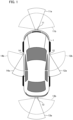
- Fig. 1 is a diagram illustrating a positional relationship between camera units and a vehicle.
- camera units 11, 12, 13, and 14 are installed, for example, on front, right, rear, and left sides of a vehicle 1 which is a mobile object (a mobile object body), respectively.
- a vehicle 1 which is a mobile object (a mobile object body)
- four camera units are provided, but the number of camera units is not limited to four and at least one camera unit may be provided.
- the camera units 11 to 14 are installed to image a front area, a right area, a left area, and a rear area of the vehicle 1 which is a mobile object as imaging areas.
- the camera units 11 to 14 have substantially the same configuration, each including an imaging device that captures an optical image and an optical system that forms an optical image on a light receiving surface of the imaging device.
- optical axes of the optical systems provided in the camera units 11 and 13 are provided to be substantially horizontal, and optical axes of the optical systems provided in the camera units 12 and 14 are provided to be directed slightly downward from the horizontal plane or to face straight down.
- the optical systems of the camera units 11 to 14 will be described below with reference to Fig. 2 . Characteristics of the optical systems of the camera units 11 to 14 may not be the same, but it is assumed that the optical systems of the camera units 11 to 14 have substantially the same characteristics, and the optical system provided in the camera unit 11 will be exemplified below.
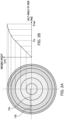
- Fig. 2A and Fig. 2B are diagrams illustrating optical characteristics of an imaging unit, where Fig. 2A is a diagram illustrating an image height y at half angle of view on the light receiving surface of the imaging device of the optical system provided in the camera unit 11 in a shape of contour lines.
- Fig. 2B is a diagram illustrating projection characteristics indicating a relationship between an image height y and a half angle of view ⁇ in the optical system provided in the camera unit 11.
- a half angle of view (an angle formed by an optical axis and incident light) ⁇ is defined as the horizontal axis
- an imaging height (image height) y on a sensor surface (an image surface) of the camera unit 11 is defined as the vertical axis.
- the optical system provided in the camera unit 11 is configured such that a projection characteristic y( ⁇ ) varies between an area less than a predetermined half angle of view ⁇ a and an area equal to or greater than the half angle of view ⁇ a as illustrated in Fig. 2B . Accordingly, when an increase in the image height y with respect to a unit half angle of view ⁇ is defined as a resolution, the resolution varies depending on the areas.
- This local resolution can also be expressed by a differential value dy( ⁇ )/d ⁇ of the projection characteristic y( ⁇ ) at the half angle of view ⁇ . That is, as the slope of the projection characteristic y( ⁇ ) in Fig. 2B increases, the resolution increases. As internals between the image heights y at the half angle of view in the shape of contour lines in Fig. 2A increase, the resolution increases.
- a high-resolution area (a first area) 10a An area on a center side (a central part) formed on a sensor surface when the half angle of view ⁇ is less than a predetermined half angle of view ⁇ a is referred to as a high-resolution area (a first area) 10a, and an area on a peripheral side (a peripheral part) in which the half angle of view ⁇ is equal to or greater than the predetermined half angle of view ⁇ a is referred to as a low-resolution area (a second area) 10b.
- the high-resolution area 10a corresponds to imaging viewing angles 11a to 14a
- the low-resolution area 10b corresponds to imaging viewing angles 11b to 14b.
- the light receiving surface includes a first area and a second area on a peripheral side of the first area, wherein an increase in an image height with respect to a unit half angle of view in the first area is larger than an increase in an image height with respect to a unit half angle of view in the second area.
- a circle of a boundary between the high-resolution area 10a and the low-resolution area 10b is referred to as a resolution boundary, and a boundary image on a display screen corresponding to the resolution boundary is referred to as a display resolution boundary or simply as a boundary image.
- the boundary image (the display resolution boundary) displayed on the display screen may not be circular.
- the boundary image may be rectangular for the purpose of convenience.
- the boundary between the high-resolution area 10a and the low-resolution area 10b may not be circular but elliptical or distorted.
- a center of gravity or gravity center of the boundary 93 may not match a position at which the optical axis of the optical system crosses the light receiving surface. However, if the gravity center of the boundary 93 (the high-resolution area 10a) substantially matches the position at which the optical axis of the optical system crosses the light receiving surface, it is possible to facilitate optical design, to obtain stable optical characteristics, and to reduce a load for distortion correction.
- the high-resolution area 10a is a low-distortion area with relatively low distortion
- the low-resolution area 10b is a high-distortion area with relatively high distortion.
- the high-resolution area and the low-resolution area correspond to a low-distortion area and a high-distortion area
- the high-resolution area and the low-resolution area may be referred to as a low-distortion area and a high-distortion area.
- the low-distortion area and the high-distortion area may be referred to as a high-resolution area and a low-resolution area.
- the optical system of the camera unit 11 is configured such that a projection characteristic y( ⁇ ) in the high-resolution area (low-distortion area) 10a is greater than f ⁇ (where f is a focal distance of the optical system of the camera unit 11).
- the projection characteristic y( ⁇ ) in the high-resolution area (low-distortion area) is set to be different from the projection characteristic in the low-resolution area (high-distortion area).
- a ratio ⁇ a/max of ⁇ a to ⁇ max is preferably equal to or greater than a predetermined lower limit and for example, the predetermined lower limit preferably ranges from 0.15 to 0.16.
- the ratio ⁇ a/max of ⁇ a to ⁇ max is preferably equal to or less than a predetermined upper limit and for example, the predetermined upper limit preferably ranges from 0.25 to 0.35.
- the predetermined lower limit is 0.15
- the predetermined upper limit is 0.35
- ⁇ a can be preferably determined to be in a range of 13.5° to 31.5°.
- the optical system of the camera unit 11 is configured such that the projection characteristic y( ⁇ ) satisfies Expression 1. 1 ⁇ f ⁇ sin ⁇ max / y ⁇ max ⁇ 1.9
- f denotes a focal distance of the optical system of the camera unit 11 as described above.
- the upper limit can be determined in consideration of a resolution balance between the high-resolution area and the low-resolution area, and can be preferably determined in a range of 1.4 to 1.9.
- a high resolution is acquired in the high-resolution area 10a, and it is possible to reduce an increase of the image height y with respect to the half angle of view ⁇ per unit and to perform imaging at a wider viewing angle in the low-resolution area 10b. Accordingly, it is possible to acquire a high resolution in the high-resolution area 10a using a wide viewing angle equivalent to that of a fish-eye lens as an imaging area.
- the projection characteristic y( ⁇ ) satisfies the conditions of Expression 1
- the same advantages can be obtained and thus the present disclosure is not limited to the projection characteristic illustrated in Fig. 2 .
- the optical system having the projection characteristic y( ⁇ ) satisfying the conditions of Expression 1 may be referred to as a different-angle-of-view lens.
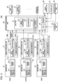
- Reference signs 31 to 34 denote camera processing units, which are accommodated in the same housings of the same camera units 11 to 14 along with the imaging units 21 to 24 and process imaging signals output from the imaging units 21 to 24.
- FIG. 3 details and wiring lines of the imaging units 24 and the camera processing units 34 are omitted for the purpose of convenience.
- the camera processing units 31 to 34 include image processing units 31a to 34a, recognition units 31b to 34b, and camera information units 31c to 34c.
- the image processing units 31a to 34a perform image processing on the imaging signals output from the imaging units 21 to 24. Some or all processes performed by the camera processing unit 31 may be performed by a stacked signal processing unit in the imaging devices 21d to 24d.
- the recognition units 31b to 34b may also perform the image recognizing process on the RAW image signals acquired from the low-resolution areas 10b. Since these RAW image signals have not been subjected distortion correction, an image of the peripheral part of each different-angle-of-view lens has high distortion and low recognition reliability.
- the output of the recognition unit 31b of the camera unit 11 installed for a front view may also be directly supplied to a travel control unit (ECU) 60. This is because travel may need to be controlled such that the vehicle stops immediately or avoids an obstacle on the basis of a recognition result of an obstacle from the recognition unit 31b.
- ECU travel control unit
- the camera information units 31c to 34c store camera information of the camera units 11 to 14 in a memory in advance.
- the camera information units may temporarily store information from various sensors and the like provided in the camera units 11 to 14.
- the camera information includes, for example, the characteristic information (such as resolution boundary information) illustrated in Fig. 2 of optical images formed by the different-angle-of-view lenses 21c to 24c.
- the camera information also includes the numbers of pixels of the imaging devices 21d to 24d, position coordinate and posture (such as pitch, roll, and yaw) information in a vehicle coordinate system of the camera units, and imaging directions.
- the camera information may include information such as gamma characteristics, sensitivity characteristics, and frame rates.
- the camera information may include information on an image processing method or an image format when the RAW image signals are generated by the image processing units 31a to 34a.
- the position coordinates for attachment may be stored in a memory in the corresponding camera information unit in advance because the attachment position of each camera unit on the vehicle is often determined.
- Posture coordinates of a camera unit are coordinates relative to the vehicle 1 and may be acquired using an encoder or the like (not illustrated) provided in the corresponding camera unit. Alternatively, the posture coordinates of each camera unit may be acquired using a three-dimensional acceleration sensor or the like.
- the camera information is information specific to the imaging units 21 to 24 and differs, and such information is transmitted to the integrated processing unit 40 and is referred to by the integrated processing unit 40 at the time of performing image processing or the like.
- the camera information units 31c to 34c serve as a storage unit that stores characteristic information of the optical characteristics thereof or position and posture information of the corresponding camera unit.
- the image processing units 31a to 34a or the recognition units 31b to 34b are configured by hardware such as a dedicated circuit (ASIC) or a processor (a reconfigurable process or a DSP). Accordingly, it is possible to realize an increase in image recognition speed in a high-resolution area and to enhance a possibility of avoidance of an accident.
- the image processing units 31a to 34a may have a distortion correcting function.
- Reference sign 40 denotes an integrated processing unit and includes a system on chip (SOC)/field programmable gate array (FPGA) 41, a CPU 42 which is a computer, and a memory 43 which is a storage medium.
- the CPU 42 performs various types of control of the image processing system 100 as a whole by executing a computer program stored in the memory 43.
- the integrated processing unit 40 is accommodated in a housing different from that for the camera units.
- the SOC/FPGA 41 includes an image processing unit 41a, a recognition unit 41b, and an integrated control unit 41c.
- the image processing unit 41a acquires RAW image signals from the corresponding camera processing units 31 to 34 and acquires camera information of the camera units 11 to 14 from the camera information units 31c to 34c.
- the camera information includes optical characteristics of the different-angle-of-view lenses 21c to 24c, the numbers of pixels, photoelectric conversion characteristics, y characteristics, and sensitivity characteristics of the imaging devices 21d to 24d, format information of RAW image signals, or position coordinates and posture information in the vehicle coordinate system of the camera units.
- the image processing unit 41a acquires camera information such as characteristic information of the optical system.
- the image processing unit 41a performs resolution conversion on the RAW image signals from the camera processing units 31 to 34 on the basis of the acquired camera information and performs an image processing step such as distortion correction on image signals acquired from the low-resolution area 10b of the imaging units 21 to 24.
- the image processing unit 41a performs distortion correction on an image signal from a distortion-correction area on the basis of the optical characteristics, and synthesizes the distortion-corrected image signal and an image signal from a non-distortion-correction area which has not been subjected to distortion correction to generate a composite image. That is, the image processing unit 41a also serves as a display signal generating unit and performs a display signal generating step of generating a composite image by performing distortion correction or the like.
- the distortion-correction area can be set by a user or automatically.
- the image processing unit 41a Since the image signal acquired from the high-resolution area 10a is hardly distorted, the image processing unit 41a does not perform distortion correction on the image signal acquired from the high-resolution area 10a. Here, the image processing unit 41a may also perform simplified distortion correction on the image signal acquired from the high-resolution area 10a.
- the image processing unit 41a appropriately an irreversible compression process or the like on the RAW image signals from the camera processing units 31 to 34.
- the image processing unit 41a synthesizes the image signal from the low-resolution area 10b of each of the imaging units 21 to 24 having performed distortion correction and the image signal from the high-resolution area 10a such that the image signals join smoothly to form the whole image for each of the imaging units 21 to 24.
- the image processing unit 41a may perform distortion correction on the RAW image signals acquired by the image processing units 31a to 34a without any change.
- the image processing unit 41a performs image processing such as rotation of an image particularly on the basis of the arrangement position and posture information of the cameras in the camera information. This will be described later.
- the recognition unit 41b performs an image recognizing process on the whole image of each of the imaging units 21 to 24 in which distortion correction has been performed on at least the low-resolution area and recognizes a predetermined object (for example, a vehicle, a person, or an obstacle) in the whole image of each of the imaging units 21 to 24. That is, after distortion correction has been performed on an image signal corresponding to at least the low-resolution area (high-distortion area), the recognition unit 41b performs image recognition and outputs a second image recognition result.
- a predetermined object for example, a vehicle, a person, or an obstacle
- the recognition unit 41b also refers to the recognition results (types or coordinates of an object) from the recognition units 31b to 34b. It is described above that the recognition unit 41b performs image recognition on the whole image of each of the imaging units 21 to 24, but image recognition does not have to be performed on the whole image. For example, a peripheral part of an image may not be subjected to image recognition.
- the recognition unit 41b has only to recognize, for example, an area including the areas recognized by the recognition units 31b to 34b and wider than the areas.
- the recognition unit 41b serves as a second image recognizing unit that performs image recognition on an image signal of an area including a partial area subjected to image recognition by the first image recognizing unit and wider than the partial area out of the image signals acquired by the image acquiring unit and outputs a second image recognition result.
- the second image recognizing unit performs image recognition on a composite image into which image signals corresponding to the high-resolution area 10a which is a low-distortion area and the low-resolution area 10b which is a high-distortion area are synthesized and outputs the second image recognition result.
- the image processing unit 41a forms a panoramic composite image by synthesizing the images from the camera units 12 to 14 which are a plurality of imaging units such that the images join.
- the images of the plurality of imaging units to join be set such that at least parts of the imaging viewing angles thereof overlap by a predetermined amount or greater.
- the camera units 12 and 13 may be disposed such that the imaging areas thereof overlap each other as will be described later.
- the camera units 13 and 14 may be disposed such that the imaging areas thereof overlap each other. At this time, the imaging areas of the low-distortion areas of at least two image acquiring units may overlap each other.
- the recognition unit 41b performs image recognition on the panoramic composite image. Accordingly, for example, it is possible to recognize an image of an object which is imaged to extend over the viewing angles of a plurality of imaging units. This is because the whole image of an object may not be recognized from the individual whole images from the imaging units, but substantially the whole image of the object may appear in the panoramic composite image and the image of the object may be able to be recognized through image processing.
- the integrated control unit 41c outputs an integrated image recognition result by employing the recognition result with higher reliability.
- a proportion occupied by an object in the image recognized by the recognition units 31b to 34b and a proportion occupied by the same object recognized by the recognition unit 41b in a screen may be compared, and the recognition result with the larger proportion may be determined to have higher reliability and be employed.
- the recognition result from the recognition unit 41b may be determined to have higher reliability than the recognition result from the recognition units 31b to 34b and be employed.
- this recognition result may be determined to have lower reliability, and the recognition result from the recognition unit 41b may be determined to have higher reliability and be employed.
- the recognition unit 41b may perform image recognition on only the low-resolution area in a state in which distortion correction has been performed on the low-resolution area, and may perform image recognition on an object extending over the low-resolution area and the high-resolution area when there is such an object. That is, an object which is located in only the high-resolution area may be considered to have high reliability of recognition using the recognition units 31b to 34b and may not be subjected to an image recognizing process by the recognition unit 41b.
- the integrated control unit 41c may generate a CG of a boundary image for displaying a boundary on the basis of characteristic information of the optical system such as display resolution boundary information acquired from the camera information units 31c to 34c.
- the integrated control unit 41c performs communication with the travel control unit (ECU) 60 and the like via a communication unit (not illustrated) provided therein using a protocol such as CAN, FlexRay, or Ethernet. Accordingly, the integrated control unit 41c performs a display process of appropriately changing information to be displayed on the basis of a vehicle control signal received from the travel control unit (ECU) 60. That is, a range of an image to be displayed on the display unit or the like is changed, for example, according to a moving state of the vehicle acquired from the vehicle control signal.
- the travel control unit (ECU) 60 is a unit that is mounted in the vehicle 1 and includes a computer or a memory for comprehensively performing drive control, direction control, and the like of the vehicle 1.
- the vehicle control signal for example, information on traveling (a moving state) of the vehicle such as a traveling speed, a traveling direction, a shift lever, a shift gear, a blinker's state, and a direction of the vehicle from a geomagnetic sensor or the like are input from the travel control unit (ECU) 60 to the integrated processing unit 40.
- the integrated control unit 41c transmits information such as a type, a position, a moving direction, and a moving speed of a predetermined object (such as an obstacle) recognized by the recognition unit 41b to the travel control unit (ECU) 60.
- the travel control unit (ECU) 60 performs control required for avoidance of an obstacle such as stopping and driving of the vehicle and changing of the traveling direction.
- the travel control unit (ECU) 60 serves as a movement control unit that controls movement of a vehicle which is a mobile object on the basis of the integrated image recognition result.
- the first display unit 50 may be installed in the vicinity of the center in a vehicle width direction of a front-upper part of a driver's seat of the vehicle 1 such that a display screen thereof faces the rear of the vehicle, and serves as an electronic rearview mirror.
- the first display unit 50 may be used as a mirror when it is not used as a display.
- the first display unit 50 may be configured to include a touch panel or an operation button, to acquire an instruction from a user, and to output information to the integrated control unit 41c.
- the second display unit 51 is installed, for example, near an instrument panel in the vicinity of the center in the vehicle width direction of the front part of the driver's seat of the vehicle 1.
- a navigation system, an audio system, and the like are mounted in the vehicle 1 which is a mobile object.
- various control signals from the navigation system, the audio system, and the travel control unit (ECU) 60 can also be displayed on the second display unit.
- the second display unit is configured to include a touch panel or an operation button and to acquire an instruction from a user.
- the second display unit 51 may be, for example, a display unit of a tablet terminal.
- the second display unit 51 may be configured to display an image through wired connection to the integrated processing unit 40 or may be configured to wirelessly receive an image via a communication unit 62 and to display the received image.
- a liquid crystal display panel, an organic EL display panel, or the like can be used as a display panel of the first display unit 50 or the second display unit 51.
- the number of display units is not limited to three.
- Some or all of the functional blocks included in the integrated processing unit 40 and the like may be realized in hardware or may be realized by causing the CPU 42 to execute a computer program stored in the memory 43.
- a dedicated circuit (ASIC), a processor (a reconfigurable process or a DSP), or the like can be used as the hardware.
- Some or all image processes which are performed by the image processing units 31a to 34a may be performed by the image processing unit 41a of the integrated processing unit 40. That is, for example, the image acquiring unit and the first image recognizing unit are accommodated in the same housing of the camera unit, and the camera unit and the second image recognizing unit are accommodated in different housings. However, for example, the first image recognizing unit along with the second image recognizing unit may be accommodated in the housing of the integrated processing unit 40.
- the integrated processing unit 40 is mounted in a vehicle 1 which is a mobile object, but some processes of the image processing unit 41a, the recognition unit 41b, and the integrated control unit 41c of the integrated processing unit 40 may be performed, for example, by an external server or the like via a network.
- the imaging units 21 to 24 which are the image acquiring unit are mounted in the vehicle 1 which is a mobile object, but, for example, some functions of the camera processing units 31 to 34 or the integrated processing unit 40 may be performed by an external server or the like. Some or all functions of the integrated processing unit 40 may be provided in the travel control unit (ECU) 60.
- ECU travel control unit
- Reference sign 61 denotes a storage unit, which stores whole images of the imaging units 21 to 24 generated by the integrated processing unit 40 or a panoramic composite image.
- a CG such as a predetermined frame indicating a recognized object, text, or warning, or an image overlapped with the CG and displayed on the first display unit 50 and the second display unit 51, and the like is stored along with time or GPS information.
- the integrated processing unit 40 can also regenerate past information stored in the storage unit 61 and display the information on the first display unit 50 or the second display unit 51.
- Reference sign 62 denotes a communication unit, which communicates with an external server or the like via a network and which can transmit information not stored yet in the storage unit 61 or past information stored in the past in the storage unit 61 to the external server or the like to store the information in the external server or the like.
- an image may be transmitted to an external tablet terminal or the like and the image may be displayed on the second display unit 51 which is a display unit of the table terminal.
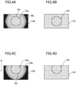
- Figs. 4A to 4D are diagrams illustrating a relationship between a light receiving surface of an imaging device of a camera unit and a high-resolution area and a low-resolution area.
- Fig. 4A is a diagram illustrating an example of a relationship the optical system of the rear camera unit 13 and the light receiving surface 130 of the imaging device
- Fig. 4B is a diagram illustrating an example of a distortion-corrected image of the rear camera unit 13.
- Fig. 4C is a diagram illustrating an example of a relationship the optical system of the left camera unit 14 and the light receiving surface 140 of the imaging device according to a first embodiment
- Fig. 4D is a diagram illustrating an example of a distortion-corrected image of the left camera unit 14 according to the first embodiment.
- an image illustrated in Fig. 2A is formed on the light receiving surface 130 of the imaging device of the rear camera unit 13.
- the substantial center of the light receiving surface 130 of the imaging device and the center of the high-resolution area 10a (the optical axis of the optical system) are disposed to substantially match.
- Reference sign 93 denotes a boundary between the high-resolution area 10a and the low-resolution area 10b, and the center of the boundary 93 substantially matches, for example, the substantial center of the light receiving surface 130 of the imaging device of the rear camera unit 13.
- the center of the boundary 93 (the high-resolution area 10a) matches a position at which the optical axis of the optical system crosses the light receiving surface.
- the center of boundary 93 is disposed substantially at the center of the screen.
- the distortion correction may be performed on the image of the high-resolution area 10a, but the distortion correction may not be performed on the image of the high-resolution area 10a.
- the image of the high-resolution area 10a having distortion correction not performed thereon and the image of the low-resolution area (high-distortion area) 10b having distortion correction performed thereon are synthesized, a process for causing boundary parts to join smoothly is necessary.
- Distortion correction is a correction process for reducing distortion and includes a process in which distortion is not zero. For example, distortion may be left in a part such as a peripheral part.
- An area having distortion correction not performed thereon is not limited to a circular high-resolution area (low-distortion area) 10a as illustrated in Fig. 4B .
- the area may have another shape such as a rectangular shape or a size or a position thereof may be changed.
- an image of an imaging viewing angle 13a of the rear camera unit 13 is formed in the high-resolution area (low-distortion area) 10a of the light receiving surface 130 as illustrated in Fig. 4A .
- An image of an imaging viewing angle 13b is formed in the low-resolution area (high-distortion area) 10b of the light receiving surface 130.
- the same relationship as illustrated in Figs. 4A and 4B is established for the front camera unit 11.
- the center of the high-resolution area (low-distortion area) 10a of the left camera unit 14 is deviated or offset from the center of the light receiving surface 140 of the imaging device to an upper side in the drawing (in a first direction) as illustrated in Fig. 4C . That is, in the left camera unit 14, the optical system and the imaging device are disposed such that the center of the boundary 93 is deviated or offset from the center of the light receiving surface 140 of the imaging device to the upper side in the drawing (in the first direction).
- the first direction is also referred to as a vignetting direction F. Accordingly, it is possible to control a range of the low-resolution area 10b which is formed on the imaging device.
- the imaging area of the low-resolution area 10b can be extended to a direction opposite to the vignetting direction F.
- a plurality of pixels are arranged in rows and columns on the light receiving surface 140 of the imaging device, and photoconverting and reading is performed row by row in a predetermined second direction (a vertical scanning direction) sequentially from the pixels in a predetermined row.
- the light receiving surface is rectangular, and the number of pixels in the length direction is larger than the number of pixels in the width direction.
- Charge signals photoconverted by the pixels of the light receiving surface of the imaging device are sequentially read row by row from an upper-left end to a lower-right end for each row when the length direction of the rectangle is defined as a lateral direction.
- the first direction is opposite to the second direction.
- the center of the boundary 93 is deviated to the upper side of the screen as illustrated in Fig. 4D . Therefore, a part of the viewing angle in the upward direction (the vignetting direction F) in Figs. 4C and 4D is lost, and the viewing angle in the downward direction can be widened in comparison with the example illustrated in Fig. 4A . As a result, it is possible to effectively use the pixels on the light receiving surface of the imaging device. The same relationship as illustrated in Figs. 4C and 4D is established for the right camera unit 12.
- the first direction is set to a direction opposite to the second direction, but the first direction and the second direction may be the same direction. In this case, a process for changing the direction of an image is necessary.
- the first direction may be set to a direction perpendicular to the second direction. In this case, a maximum number of pixels may not be effectively used.
- the first direction and the second direction may be set to have an appropriate angle.
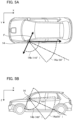
- Figs. 5A to 7B are diagrams illustrating an arrangement example of the left camera unit 14, where Figs. 5A and 5B are diagrams illustrating an example of the first embodiment in which the imaging device of the camera unit 14 is vertically arranged and the optical axis of the optical system is directed slightly downward with respect to the horizontal direction on the rear-left side of the vehicle 1.
- Fig. 5A is a diagram illustrating a top view of the vehicle 1 according to the first embodiment
- Fig. 5B is a diagram illustrating a left side view of the vehicle 1 according to the first embodiment.
- the upward direction (the vignetting direction F) of the imaging device in Fig. 4C is disposed to face the vehicle 1 as illustrated in Fig. 5A . That is, the first direction (the vignetting direction F) is a direction perpendicular to the vertical direction and is disposed to face the mobile object.
- a vehicle body which is an untargeted area may not be imaged on the imaging device and the imaging viewing angle 14b corresponding to the low-resolution area 10b which can be imaged is extended to the front-left side. Accordingly, it is possible to facilitate recognition of an obstacle or the like on the front-left side.
- the number of pixels in the height direction (the Z direction) is larger than the number of pixels in the width direction (the Y direction) of the vehicle 1, and the optical axis of the optical system is directed outward with respect to a side line of the vehicle 1 in the length direction (the X direction) of the vehicle 1.
- the optical axis is indicated by a one-dot chain line.
- the optical axis of the optical system is disposed in the horizontal direction or downward with respect to the horizontal direction.
- the high-resolution area 10a can be more used as display for the electronic rearview mirror, a driver can accurately confirm the rear-lateral side and a blind spot on the front-lateral side in the low-resolution area 10b can be imaged with the low-resolution area 10b.
- the viewing angle of the low-resolution area 10b in the height direction of the vehicle 1 can include a front wheel and thus it is possible to sufficiently visually recognize a blind spot on the front-lateral side, which is very effective when the vehicle parks in a narrow space or the like.
- Figs. 5A and 5B the left camera unit 14 is illustrated, but the right camera unit 12 can be disposed to be symmetric. In this case, the same advantages can be achieved.
- the image processing unit 41a of the integrated processing unit 40 rotates and displays an image from the camera unit 14 on the basis of position and posture information of a camera in the camera information.
- the image from the camera unit 14 is synthesized with an image from the rear camera unit 13 and the composite image is displayed according to necessity.
- the image processing unit 41a rotates and displays an image from the camera unit 12 on the basis of position and posture information of a camera in the camera information.
- the image from the camera unit 12 is synthesized with an image from the rear camera unit 13 and the composite image is displayed according to necessity.
- the image processing unit 41a displays the images from the camera units 11 and 13 without rotating the images on the basis of the position and posture information of the camera. Alternatively, the image is synthesized with another image.
- the camera unit includes an imaging device and an optical system configured to form an optical image on a light receiving surface of the imaging device, and the light receiving surface includes a high-resolution area and a low-resolution area in a peripheral part of the high-resolution area.
- the optical system and the imaging device are disposed such that the gravity center of the high-resolution area deviates in a first direction from the center of the light receiving surface, and the camera unit is installed such that the first direction is directed to an area other than a predetermined targeted area.
- an untargeted area may not be formed on the imaging device and the imaging viewing angle 14b corresponding to the low-resolution area 10b which can be imaged is extended to the targeted area, it is possible to easily recognize an obstacle or the like in the targeted area.
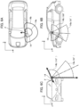
- Figs. 6A to 6C are diagrams illustrating an example of a second embodiment in which the imaging device of the camera unit 14 is vertically disposed and the optical axis of the optical system is disposed just downward on the rear-left side of a vehicle 1.
- Fig. 6A is a diagram illustrating a top view of the vehicle 1 according to the second embodiment
- Fig. 6B is a diagram illustrating a left side view of the vehicle 1 according to the second embodiment
- Fig. 6C is a diagram illustrating a front view of the vehicle 1 according to the second embodiment.
- the upward direction (the vignetting direction F) of the imaging device in Fig. 4C is directed to face the vehicle 1 as illustrated in Figs. 6A and 6C .
- the number of pixels in the length direction (the X direction) of the vehicle 1 is larger than the number of pixels in the width direction (the Y direction) of the vehicle 1, and the optical axis of the optical system is directed outward with respect to the downward vertical direction in the width direction (the Y direction) of the vehicle 1 as illustrated in Fig. 6C .
- the optical axis of the optical system is disposed substantially downward along the vertical direction. As illustrated in Fig. 6C , the optical axis is inclined outward from the vertical direction on one side of the vehicle 1.
- the imaging viewing angle 14a corresponding to the high-resolution area 10a is slightly narrowed to, for example, 50 degrees as in the front view illustrated in Fig. 6C .
- the imaging viewing angle 14b corresponding to the low-resolution area 10b includes a front-lower side of the vehicle 1 to the rear-lower side as illustrated in Fig. 6B , an obstacle or the like on the lower side can be more easily recognized than in the example illustrated in Figs. 5A and 5B .
- the imaging viewing angle 14a corresponding to the high-resolution area 10a is assigned to a blind spot on the front-lateral side, it is possible to confirm the blind spot on the front-lateral side with a high resolution.
- the imaging viewing angle 14a corresponding to the high-resolution area 10a
- the light receiving surface of the imaging device can be effectively used to obtain a down-around-view image around the vehicle 1, and it is possible to greatly reduce a blind spot particularly in case of a large truck or the like.
- the left camera unit 14 has been described above with reference to Figs. 6A to 6C , but the right camera unit 12 can also be arranged to be symmetric therewith. In this case, the same advantages can be achieved.
- the image processing unit 41a of the integrated processing unit 40 rotates an image from the camera unit 14 particularly on the basis of position and posture information of the camera in the camera information.
- the image from the camera unit 14 is synthesized with an image from the rear camera unit 13 and the composite image is displayed according to necessity.
- the image processing unit 41a rotates and displays an image from the camera unit 12 on the basis of position and posture information of the camera in the camera information.
- the image from the camera unit 12 is synthesized with an image from the rear camera unit 13 and the composite image is displayed according to necessity.
- Figs. 7A and 7B are diagrams illustrating an example of a third embodiment in which the imaging device of the camera unit 14 is horizontally disposed and the optical axis of the optical system is disposed slightly downward with respect to the horizontal direction on the rear-left side of a vehicle 1.
- Fig. 7A is a diagram illustrating a top view of the vehicle 1 according to the third embodiment
- Fig. 7B is a diagram illustrating a left side view of the vehicle 1 according to the third embodiment.
- the upward direction (the vignetting direction F) of the imaging device in Fig. 4C is directed to face a sky area as illustrated in Fig. 7B . That is, the vignetting direction F is directed upward with respect to the horizontal plane.
- a second direction (a sequential row reading direction) of the imaging device is directed downward with respect to the horizontal plane. That is, the first direction is not parallel to a horizontal scanning direction.
- the vignetting direction can be set to a direction to the sky area which is an untargeted area.
- the imaging viewing angle 14a corresponding to the high-resolution area 10a is slightly narrowed to, for example, 50 degrees and the imaging viewing angle 14b corresponding to the left low-resolution area 10b is widened to the front-left side, it is possible to recognize an obstacle or the like on the front-left side.
- the number of pixels in the width direction (the Y direction) is larger than the number of pixels in the height direction (the Z direction) of the vehicle 1, and the optical axis of the optical system is disposed outward with respect to the side line of the vehicle 1 in the length direction (the X direction) of the vehicle 1.
- the optical axis of the optical system is disposed horizontally or downward with respect to the horizontal plane.
- the vignetting viewing angle is directed to the sky side in which there are little obstacles and thus it is possible to effectively use the light receiving surface of the imaging device.
- the high-resolution area 10a can be more used as display for the electronic rearview mirror, a driver can accurately confirm the rear side and a blind spot on the front-lateral side in the low-resolution area 10b can be imaged with the imaging viewing angle 14b corresponding to the low-resolution area 10b.
- the imaging viewing angle 14a corresponding to the high-resolution area 10a includes a part of the vehicle 1, it is possible to easily feel a sense of distance to an obstacle or the like.
- the height direction (the Z direction) of the vehicle 1 since a front wheel can be included in the imaging viewing angle 14b corresponding to the low-resolution area 10b, it is possible to sufficiently visually recognize a blind spot on the front-lateral side, which is very effective when the vehicle parks in a narrow space or the like.
- Figs. 7A and 7B the left camera unit 14 is illustrated, but the right camera unit 12 can be disposed to be symmetric therewith. In this case, the same advantages can be achieved.
- the image processing unit 41a of the integrated processing unit 40 displays an image without rotating the image when the camera unit 14 is disposed as illustrated in Figs. 6A to 6C particularly on the basis of position and posture information of the camera in the camera information.
- the image from the camera unit 14 is synthesized with an image from the rear camera unit 13 and the composite image is displayed according to necessity.
- the image processing unit 41a displays an image from the camera unit 12 without rotating the image on the basis of position and posture information of the camera in the camera information.
- the image from the camera unit 12 is synthesized with an image from the rear camera unit 13 and the composite image is displayed according to necessity.
- the center of the high-resolution area 10a of the optical system including the high-resolution area 10a and the low-resolution area (high-distortion area) 10b is intentionally deviated from the center of the light receiving surface of the imaging device. Accordingly, a part of the viewing angle is lost out and the other side of the viewing angle is extended.
- the vignetting direction (the first direction) is directed to an area other than a targeted area, it is possible to optimize the imaging viewing angle and to most effectively use the pixels of the imaging device.
- An amount of deviation between the center of the high-resolution area 10a and the center of the light receiving surface of the imaging device, or the like can be changed according to applications or positions.
- the arrangement illustrated in Figs. 4A and 4B can be achieved by reducing the amount of deviation or making it zero.
- the amount of deviation can be simply increased as illustrated in Figs. 4C and 4D .
- the targeted area includes an area in which an obstacle is assumed to be present such as an area on an obliquely rear-lateral side of the vehicle 1 or an outer peripheral area of a wheel, for example, when a camera unit is installed on a lateral side of the vehicle 1.
- the vignetting direction (the first direction) is directed to the vehicle 1 (or the installation position) or the sky area other than the targeted area.
- the targeted area changes according to applications in which the camera unit is installed.
- the solution of an image of the high-resolution area (low-distortion area) 10a displayed on the first display unit 50 or the second display unit 51 is higher than that of the low-resolution area (low-distortion area) 10b, and thus it is possible to more accurately display far images of the front view, the side view, and the rear view of the vehicle 1.
- the present disclosure is more advantageous in terms of costs, processing efficiency, decrease in size, and the like in comparison with a case in which a plurality of camera units with different viewing angles are used.
- an image for the electronic rearview mirror displayed on the first display unit 50 can be displayed in a low-distortion state and thus a driver can visually recognize the surroundings of the vehicle with a more natural perspective feeling.
- the high-resolution area 10a is configured to have low optical distortion and image recognition can be performed thereon in a state of a RAW image signal of which distortion has not been corrected, it is possible to reduce a processing load for image recognition and to perform image recognition at a high speed.
- the case in which distortion correction is not performed includes a case in which a distortion correction factor is less than a predetermined value X1.
- the case in which distortion correction is performed may include a case in which the distortion correction factor is greater than a predetermined value X2 (where X2 is equal to or greater than X1), where X1 may be set to, for example, 10% and X2 may be set to, for example, 90%.
- the present disclosure is not limited to two types of distortion correction factors, but may employ a configuration in which the distortion correction factor changes gradually.
- the present disclosure includes such embodiments.
- a boundary image indicating a boundary between an area in which distortion correction is performed and an area in which distortion correction is not performed may be able to be displayed, for example, while the vehicle is normally traveling.
- the aforementioned boundary may be displayed to reduce a feeling of discomfort.
- a width, a concentration, a color, or the like of a line of the boundary image may be changed to reduce a feeling of discomfort between the distortion-corrected area and the non-distortion-corrected area.
- the distortion correction factor in the distortion-corrected area may be adjusted depending on the size and shape of the boundary image, and the images of the distortion-corrected area and the non-distortion-corrected area for a stationary object may be smoothly joined.
- the boundary image may be displayed. Accordingly, the boundary between the distortion-corrected area and the non-distortion-corrected area becomes clear and thus it is possible to efficiently perform the adjustment operation.
- the image processing system is mounted in a mobile object such as a vehicle
- a mobile object such as a vehicle
- the mobile object according to the embodiments is not limited to a vehicle such as an automobile, but may be any of a train, a ship, an aircraft, a robot, and a drone as long as it is a movable object.
- the image processing system according to the embodiments may or may not be mounted in such a mobile object.
- the configurations according to the embodiments can also be applied to a case in which a mobile object is remotely controlled.
- At least one of various functions, processes, and methods described above in the first to third embodiments may be realized using a program.
- a program for realizing at least one of various functions, processes, and methods described above in the first embodiment is referred to as a "program X.”
- a computer that executes the program X is referred to as a "computer Y.”
- Examples of the computer Y include a personal computer, a microcomputer, and a central processing unit (CPU).
- the computer of the image processing system or the like according to the aforementioned embodiments is also an example of the computer Y.
- At least one of various functions, processes, and methods described above in the first to third embodiments can be realized by causing the computer Y to execute the program X.
- the program X is supplied to the computer Y via a computer-readable storage medium.
- the computer-readable storage medium according to the fourth embodiment includes at least one of a hard disk device, a magnetic storage device, an optical storage device, a magneto-optical storage device, a memory card, a ROM, and a RAM.
- the computer-readable storage medium according to the fourth embodiment is a non-transitory storage medium.
Landscapes
- Engineering & Computer Science (AREA)
- Multimedia (AREA)
- Physics & Mathematics (AREA)
- General Physics & Mathematics (AREA)
- Mechanical Engineering (AREA)
- Signal Processing (AREA)
- Studio Devices (AREA)
- Stereoscopic And Panoramic Photography (AREA)
- Closed-Circuit Television Systems (AREA)
Claims (19)
- Verfahren zum Installieren einer Kameraeinheit (22), die eine Abbildungsvorrichtung (22d) und ein optisches System (22c) enthält, das ein optisches Bild auf eine Abbildungsebene projiziert, die eine Lichtempfangsfläche (140) der Abbildungsvorrichtung enthält,wobei das optische System (22c) eine Projektionscharakteristik aufweist, die konfiguriert ist, ein Bild auf der Abbildungsebene zu bilden, das eine Zunahme einer Bildhöhe (y) in Bezug auf eine Einheit eines Bildhalbwinkels in einem ersten Bereich (10a) aufweist, die größer ist als eine Zunahme einer Bildhöhe in Bezug auf eine Einheit eines Bildhalbwinkels in einem zweiten Bereich (10b) auf einer Peripherieseite des ersten Bereichs (10a),wobei mindestens ein Abschnitt des ersten Bereichs (10a) und mindestens ein Abschnitt des zweiten Bereichs (10b) auf die Lichtempfangsfläche (140) projiziert werden,wobei das optische System (22c) und die Abbildungsvorrichtung (22d) so angeordnet sind, dass ein Schwerpunkt des ersten Bereichs (10a) in einer ersten Richtung (F) von einem Mittelpunkt der Lichtempfangsfläche (140) versetzt ist, undwobei das Verfahren das Installieren der Kameraeinheit enthält, so dass die erste Richtung auf einen anderen Bereich als einen vorbestimmten Zielbereich gerichtet ist,dadurch gekennzeichnet dadurch, dass, wenn eine Brennweite des optischen Systems mit f bezeichnet wird, ein maximaler Bildhalbwinkel des optischen Systems mit θmax bezeichnet wird, eine Bildhöhe auf einer Abbildungsfläche mit y bezeichnet wird und eine Projektionscharakteristik, die eine Beziehung zwischen der Bildhöhe y und dem Bildhalbwinkel θ angibt, mit y(θ) bezeichnet wird, ein Bedingungsausdruck 1,0 < f × sinθmax/y(θmax) ≤ 1,9 erfüllt ist.
- Verfahren zum Installieren einer Kameraeinheit nach Anspruch 1, wobei
das optische System so angeordnet ist, dass eine optische Achse des optischen Systems die Lichtempfangsfläche in einer Position am Schwerpunkt des ersten Bereichs (10a) schneidet. - Verfahren zum Installieren einer Kameraeinheit nach Anspruch 1 oder 2,
wobei eine Verzeichnung des optischen Systems, die dem ersten Bereich entspricht, kleiner ist als eine Verzeichnung des optischen Systems, die dem zweiten Bereich entspricht. - Verfahren zum Installieren einer Kameraeinheit nach einem der vorhergehenden Ansprüche, wobei, wenn eine Brennweite des optischen Systems mit f bezeichnet wird, ein Bildhalbwinkel mit θ bezeichnet wird, eine Bildhöhe auf einer Abbildungsfläche mit y bezeichnet wird und eine Projektionscharakteristik, die eine Beziehung zwischen der Bildhöhe y und dem Bildhalbwinkel θ angibt, mit y(θ) bezeichnet wird, ein Wert von y(θ) in dem Bereich mit geringer Verzeichnung größer als f × θ ist.
- Verfahren zum Installieren einer Kameraeinheit nach einem der vorhergehenden Ansprüche, wobei eine Projektionscharakteristik des optischen Systems, die dem ersten Bereich entspricht, und eine Projektionscharakteristik des optischen Systems, die dem zweiten Bereich entspricht, voneinander verschieden sind.
- Verfahren zum Installieren einer Kameraeinheit nach einem der vorhergehenden Ansprüche, wobei die Abbildungsvorrichtung konfiguriert ist, sequentiell eine fotoelektrische Umwandlung Zeile für Zeile in einer zweiten Richtung von Pixeln in einer vorbestimmten Zeile aus mehreren Pixeln in der Abbildungsvorrichtung durchzuführen, und die erste Richtung eine Richtung ist, die der zweiten Richtung entgegengesetzt ist.
- Verfahren zum Installieren einer Kameraeinheit nach einem der vorhergehenden Ansprüche, wobei die erste Richtung nicht parallel zu einer horizontalen Abtastrichtung ist.
- Verfahren zum Installieren einer Kameraeinheit nach einem der vorhergehenden Ansprüche, wobei die Kameraeinheit in einem mobilen Objekt installiert ist und die erste Richtung auf das mobile Objekt gerichtet ist.
- Verfahren zum Installieren einer Kameraeinheit nach einem der vorhergehenden Ansprüche, wobei eine optische Achse des optischen Systems derart installiert ist, dass sie in eine horizontale Richtung oder in Bezug auf die horizontale Richtung nach unten gerichtet ist.
- Verfahren zum Installieren einer Kameraeinheit nach Anspruch 9, wobei
die optische Achse des optischen Systems derart installiert ist, dass sie in einer vertikalen Richtung nach unten gerichtet ist. - Verfahren zum Installieren einer Kameraeinheit nach einem der vorhergehenden Ansprüche, wobei die Kameraeinheit eine Speichereinheit enthält, die konfiguriert ist, Information über eine Position und eine Stellung der Kameraeinheit zu speichern.
- Bildverarbeitungssystem, das eine Kameraeinheit und mindestens einen Prozessor oder eine Schaltung umfasst, der/die konfiguriert ist, als eine Bildverarbeitungseinheit (32) zu funktionieren, die konfiguriert ist, ein von der Kameraeinheit (22) erfasstes Bildsignal auf der Grundlage von Information über eine Position und eine Stellung der Kameraeinheit zu verarbeiten,wobei die Kameraeinheiteine Abbildungsvorrichtung (22d) und ein optisches System (22c) enthält, das ein optisches Bild auf eine Abbildungsebene projiziert, die eine Lichtempfangsfläche (140) der Abbildungsvorrichtung enthält,wobei das optische System (22c) eine Projektionscharakteristik aufweist, die konfiguriert ist, ein Bild auf der Abbildungsebene zu bilden, das eine Zunahme einer Bildhöhe in Bezug auf eine Einheit eines Bildhalbwinkels in einem ersten Bereich (10a) aufweist, die größer ist als eine Zunahme einer Bildhöhe in Bezug auf eine Einheit eines Bildhalbwinkels in einem zweiten Bereich (10b) auf einer Peripherieseite des ersten Bereichs (10a),wobei mindestens ein Abschnitt des ersten Bereichs (10a) und mindestens ein Abschnitt des zweiten Bereichs (10b) auf die Lichtempfangsfläche (140) projiziert werden,wobei das optische System (22c) und die Abbildungsvorrichtung (22d) so angeordnet sind, dass ein Schwerpunkt des ersten Bereichs (10a) in einer ersten Richtung (F) von einem Mittelpunkt der Lichtempfangsfläche (140) versetzt ist, undwobei die Kameraeinheit derart installiert ist, dass die erste Richtung auf einen anderen Bereich als einen vorbestimmten Zielbereich gerichtet ist,dadurch gekennzeichnet, dass, wenn eine Brennweite des optischen Systems mit f bezeichnet wird, ein maximaler Bildhalbwinkel des optischen Systems mit θmax bezeichnet wird, eine Bildhöhe auf einer Abbildungsfläche mit y bezeichnet wird und eine Projektionscharakteristik, die eine Beziehung zwischen der Bildhöhe y und dem Bildhalbwinkel θ angibt, mit y(θ) bezeichnet wird, ein Bedingungsausdruck 1,0 < f × sinθmax/y(θmax) ≤ 1,9 erfüllt ist.
- Bildverarbeitungssystem nach Anspruch 12, wobei die Bildverarbeitungseinheit (32) eine Verzeichnungskorrektur an einem Bildsignal von der Abbildungsvorrichtung auf der Grundlage von charakteristischer Information des optischen Systems durchführt.
- Bildverarbeitungssystem nach Anspruch 12 oder 13, wobei die Bildverarbeitungseinheit (32) eine Bilderkennung an einem Bildsignal von der Abbildungsvorrichtung durchführt.
- Bildverarbeitungssystem nach Anspruch 12, 13 oder 14, wobei
die Bildverarbeitungseinheit ein zusammengesetztes Bild durch Synthetisieren von Bildsignalen von mehreren der Kameraeinheiten erzeugt und die Bilderkennung am zusammengesetzten Bild durchführt. - Bildverarbeitungssystem nach Anspruch 15, wobei Abbildungsbereiche von mindestens zwei Kameraeinheiten einander überlappen.
- Mobiles Objekt, das ein Bildverarbeitungssystem nach einem der Ansprüche 12 bis 16 und einen mobilen Objektkörper (1) umfasst, in dem das Bildverarbeitungssystem installiert ist.
- Mobiles Objekt nach Anspruch 17, wobei die Kameraeinheit derart angeordnet ist, dass die erste Richtung in Bezug auf eine horizontale Ebene nach oben gerichtet ist.
- Mobiles Objekt nach Anspruch 17 oder 18, wobei die Kameraeinheit derart installiert ist, dass die erste Richtung auf den mobilen Objektkörper gerichtet ist.
Applications Claiming Priority (1)
| Application Number | Priority Date | Filing Date | Title |
|---|---|---|---|
| JP2021155782A JP2023046930A (ja) | 2021-09-24 | 2021-09-24 | カメラユニットの設置方法、移動体、画像処理システム、画像処理方法、およびコンピュータプログラム |
Publications (2)
| Publication Number | Publication Date |
|---|---|
| EP4155817A1 EP4155817A1 (de) | 2023-03-29 |
| EP4155817B1 true EP4155817B1 (de) | 2025-06-25 |
Family
ID=83271208
Family Applications (1)
| Application Number | Title | Priority Date | Filing Date |
|---|---|---|---|
| EP22194687.4A Active EP4155817B1 (de) | 2021-09-24 | 2022-09-08 | Verfahren zur installation einer kameraeinheit, mobiles objekt, bildverarbeitungssystem, bildverarbeitungsverfahren und speichermedium |
Country Status (4)
| Country | Link |
|---|---|
| US (1) | US12214733B2 (de) |
| EP (1) | EP4155817B1 (de) |
| JP (1) | JP2023046930A (de) |
| CN (1) | CN115883776A (de) |
Families Citing this family (7)
| Publication number | Priority date | Publication date | Assignee | Title |
|---|---|---|---|---|
| JP7732463B2 (ja) * | 2020-10-23 | 2025-09-02 | ソニーグループ株式会社 | カメラモジュール、情報処理システム、情報処理方法、及び、情報処理装置 |
| DE102021111200A1 (de) * | 2021-04-30 | 2022-11-03 | Bayerische Motoren Werke Aktiengesellschaft | Geräteträger für ein Fahrzeug |
| JP2023178051A (ja) * | 2022-06-03 | 2023-12-14 | キヤノン株式会社 | 移動体、移動体の制御方法、及びコンピュータプログラム |
| CN119541169A (zh) * | 2023-08-31 | 2025-02-28 | 鸿海精密工业股份有限公司 | 盲区预警方法、装置、电子设备及存储介质 |
| US20250095121A1 (en) * | 2023-09-15 | 2025-03-20 | Robert Bosch Gmbh | Device and method for surround view camera system with reduced manhattan effect distortion |
| JP2025062393A (ja) * | 2023-10-02 | 2025-04-14 | キヤノン株式会社 | 撮像装置及び移動体 |
| US12519922B1 (en) * | 2024-09-25 | 2026-01-06 | Microsoft Technology Licensing, Llc | Adjustment of a monocular display parameter to display content |
Family Cites Families (16)
| Publication number | Priority date | Publication date | Assignee | Title |
|---|---|---|---|---|
| JP2004345554A (ja) | 2003-05-23 | 2004-12-09 | Clarion Co Ltd | 車両後方モニタ装置及び車両後方モニタシステム |
| JP2004354572A (ja) * | 2003-05-28 | 2004-12-16 | Minolta Co Ltd | 撮像装置 |
| JP4766841B2 (ja) * | 2003-09-08 | 2011-09-07 | 株式会社オートネットワーク技術研究所 | 車両に搭載されるカメラ装置及び車両周辺監視装置 |
| JP2005110202A (ja) * | 2003-09-08 | 2005-04-21 | Auto Network Gijutsu Kenkyusho:Kk | カメラ装置及び車両周辺監視装置 |
| JP2007038856A (ja) * | 2005-08-03 | 2007-02-15 | Auto Network Gijutsu Kenkyusho:Kk | 車両周辺視認装置 |
| JP2010095202A (ja) | 2008-10-19 | 2010-04-30 | Alpine Electronics Inc | ルームミラー位置後視カメラ画像表示装置 |
| JP2013172011A (ja) * | 2012-02-21 | 2013-09-02 | Panasonic Corp | 部品実装装置、撮像装置および撮像方法 |
| JP6025365B2 (ja) * | 2012-04-04 | 2016-11-16 | 京セラ株式会社 | 較正処理装置、カメラ較正装置、カメラシステム、およびカメラ較正方法 |
| JP2015121591A (ja) * | 2013-12-20 | 2015-07-02 | 株式会社富士通ゼネラル | 車載カメラ |
| US10525883B2 (en) * | 2014-06-13 | 2020-01-07 | Magna Electronics Inc. | Vehicle vision system with panoramic view |
| WO2018016305A1 (ja) * | 2016-07-22 | 2018-01-25 | パナソニックIpマネジメント株式会社 | 撮像システム、および、移動体システム |
| JP7266165B2 (ja) * | 2017-12-19 | 2023-04-28 | パナソニックIpマネジメント株式会社 | 撮像装置、撮像システム、および表示システム |
| JP7135339B2 (ja) * | 2018-02-28 | 2022-09-13 | 株式会社デンソー | 車両に搭載される撮像システム、対象物識別装置、および対象物識別方法 |
| US20220080902A1 (en) * | 2019-01-23 | 2022-03-17 | Sony Semiconductor Solutions Corporation | Vehicle-mounted camera |
| GB2582263B (en) * | 2019-03-02 | 2023-10-11 | Jaguar Land Rover Ltd | A camera assembly and a method |
| JP7279438B2 (ja) * | 2019-03-19 | 2023-05-23 | 株式会社リコー | 撮像装置、車両及び撮像方法 |
-
2021
- 2021-09-24 JP JP2021155782A patent/JP2023046930A/ja active Pending
-
2022
- 2022-09-08 EP EP22194687.4A patent/EP4155817B1/de active Active
- 2022-09-20 US US17/933,676 patent/US12214733B2/en active Active
- 2022-09-20 CN CN202211141129.5A patent/CN115883776A/zh active Pending
Also Published As
| Publication number | Publication date |
|---|---|
| JP2023046930A (ja) | 2023-04-05 |
| EP4155817A1 (de) | 2023-03-29 |
| CN115883776A (zh) | 2023-03-31 |
| US12214733B2 (en) | 2025-02-04 |
| US20230096414A1 (en) | 2023-03-30 |
Similar Documents
| Publication | Publication Date | Title |
|---|---|---|
| EP4155817B1 (de) | Verfahren zur installation einer kameraeinheit, mobiles objekt, bildverarbeitungssystem, bildverarbeitungsverfahren und speichermedium | |
| US12325361B2 (en) | Mobile object, image processing method, and storage medium | |
| US12165419B2 (en) | Movable apparatus, control method for movable apparatus, and storage medium | |
| US12028603B2 (en) | Image processing system, image processing method, storage medium, image pickup apparatus, and optical unit | |
| JP7631275B2 (ja) | 移動体及び撮像装置の設置方法 | |
| US12417642B2 (en) | System to integrate high distortion wide-angle camera recognition with low distortion normal-angle camera recognition | |
| US12387455B2 (en) | Image processing system, mobile object, image processing method, and storage medium, with output of image recognition result integrtated on basis of first result regarding image recognition on at least partial region and second result regarding image recognition on wider region | |
| US12406344B2 (en) | Image processing system, image processing method, and storage medium | |
| JP7622025B2 (ja) | 画像処理システム、画像処理方法、およびコンピュータプログラム | |
| EP4408006A1 (de) | Bildverarbeitungssystem, bewegliche vorrichtung, bildverarbeitungsverfahren und speichermedium | |
| JP7434476B2 (ja) | 画像処理システム、画像処理方法、撮像装置、光学系、およびコンピュータプログラム | |
| US12470839B2 (en) | Movable apparatus and installation method for imaging device | |
| CN118665346A (zh) | 可移动设备、图像处理设备、存储介质和摄像设备的安装方法 |
Legal Events
| Date | Code | Title | Description |
|---|---|---|---|
| PUAI | Public reference made under article 153(3) epc to a published international application that has entered the european phase |
Free format text: ORIGINAL CODE: 0009012 |
|
| STAA | Information on the status of an ep patent application or granted ep patent |
Free format text: STATUS: THE APPLICATION HAS BEEN PUBLISHED |
|
| AK | Designated contracting states |
Kind code of ref document: A1 Designated state(s): AL AT BE BG CH CY CZ DE DK EE ES FI FR GB GR HR HU IE IS IT LI LT LU LV MC MK MT NL NO PL PT RO RS SE SI SK SM TR |
|
| STAA | Information on the status of an ep patent application or granted ep patent |
Free format text: STATUS: REQUEST FOR EXAMINATION WAS MADE |
|
| 17P | Request for examination filed |
Effective date: 20230929 |
|
| RBV | Designated contracting states (corrected) |
Designated state(s): AL AT BE BG CH CY CZ DE DK EE ES FI FR GB GR HR HU IE IS IT LI LT LU LV MC MK MT NL NO PL PT RO RS SE SI SK SM TR |
|
| STAA | Information on the status of an ep patent application or granted ep patent |
Free format text: STATUS: EXAMINATION IS IN PROGRESS |
|
| 17Q | First examination report despatched |
Effective date: 20240913 |
|
| GRAP | Despatch of communication of intention to grant a patent |
Free format text: ORIGINAL CODE: EPIDOSNIGR1 |
|
| STAA | Information on the status of an ep patent application or granted ep patent |
Free format text: STATUS: GRANT OF PATENT IS INTENDED |
|
| INTG | Intention to grant announced |
Effective date: 20250204 |
|
| GRAS | Grant fee paid |
Free format text: ORIGINAL CODE: EPIDOSNIGR3 |
|
| GRAA | (expected) grant |
Free format text: ORIGINAL CODE: 0009210 |
|
| STAA | Information on the status of an ep patent application or granted ep patent |
Free format text: STATUS: THE PATENT HAS BEEN GRANTED |
|
| AK | Designated contracting states |
Kind code of ref document: B1 Designated state(s): AL AT BE BG CH CY CZ DE DK EE ES FI FR GB GR HR HU IE IS IT LI LT LU LV MC MK MT NL NO PL PT RO RS SE SI SK SM TR |
|
| REG | Reference to a national code |
Ref country code: GB Ref legal event code: FG4D |
|
| REG | Reference to a national code |
Ref country code: CH Ref legal event code: EP |
|
| REG | Reference to a national code |
Ref country code: CH Ref legal event code: EP |
|
| REG | Reference to a national code |
Ref country code: IE Ref legal event code: FG4D |
|
| REG | Reference to a national code |
Ref country code: DE Ref legal event code: R096 Ref document number: 602022016356 Country of ref document: DE |
|
| PG25 | Lapsed in a contracting state [announced via postgrant information from national office to epo] |
Ref country code: FI Free format text: LAPSE BECAUSE OF FAILURE TO SUBMIT A TRANSLATION OF THE DESCRIPTION OR TO PAY THE FEE WITHIN THE PRESCRIBED TIME-LIMIT Effective date: 20250625 |
|
| PGFP | Annual fee paid to national office [announced via postgrant information from national office to epo] |
Ref country code: DE Payment date: 20250820 Year of fee payment: 4 |
|
| REG | Reference to a national code |
Ref country code: LT Ref legal event code: MG9D |
|
| PG25 | Lapsed in a contracting state [announced via postgrant information from national office to epo] |
Ref country code: NO Free format text: LAPSE BECAUSE OF FAILURE TO SUBMIT A TRANSLATION OF THE DESCRIPTION OR TO PAY THE FEE WITHIN THE PRESCRIBED TIME-LIMIT Effective date: 20250925 Ref country code: GR Free format text: LAPSE BECAUSE OF FAILURE TO SUBMIT A TRANSLATION OF THE DESCRIPTION OR TO PAY THE FEE WITHIN THE PRESCRIBED TIME-LIMIT Effective date: 20250926 |
|
| PG25 | Lapsed in a contracting state [announced via postgrant information from national office to epo] |
Ref country code: BG Free format text: LAPSE BECAUSE OF FAILURE TO SUBMIT A TRANSLATION OF THE DESCRIPTION OR TO PAY THE FEE WITHIN THE PRESCRIBED TIME-LIMIT Effective date: 20250625 |
|
| PG25 | Lapsed in a contracting state [announced via postgrant information from national office to epo] |
Ref country code: HR Free format text: LAPSE BECAUSE OF FAILURE TO SUBMIT A TRANSLATION OF THE DESCRIPTION OR TO PAY THE FEE WITHIN THE PRESCRIBED TIME-LIMIT Effective date: 20250625 |
|
| PGFP | Annual fee paid to national office [announced via postgrant information from national office to epo] |
Ref country code: AT Payment date: 20251020 Year of fee payment: 4 |
|
| PG25 | Lapsed in a contracting state [announced via postgrant information from national office to epo] |
Ref country code: RS Free format text: LAPSE BECAUSE OF FAILURE TO SUBMIT A TRANSLATION OF THE DESCRIPTION OR TO PAY THE FEE WITHIN THE PRESCRIBED TIME-LIMIT Effective date: 20250925 |
|
| PG25 | Lapsed in a contracting state [announced via postgrant information from national office to epo] |
Ref country code: LV Free format text: LAPSE BECAUSE OF FAILURE TO SUBMIT A TRANSLATION OF THE DESCRIPTION OR TO PAY THE FEE WITHIN THE PRESCRIBED TIME-LIMIT Effective date: 20250625 |
|
| REG | Reference to a national code |
Ref country code: NL Ref legal event code: MP Effective date: 20250625 |
|
| PG25 | Lapsed in a contracting state [announced via postgrant information from national office to epo] |
Ref country code: NL Free format text: LAPSE BECAUSE OF FAILURE TO SUBMIT A TRANSLATION OF THE DESCRIPTION OR TO PAY THE FEE WITHIN THE PRESCRIBED TIME-LIMIT Effective date: 20250625 |
|
| PG25 | Lapsed in a contracting state [announced via postgrant information from national office to epo] |
Ref country code: PT Free format text: LAPSE BECAUSE OF FAILURE TO SUBMIT A TRANSLATION OF THE DESCRIPTION OR TO PAY THE FEE WITHIN THE PRESCRIBED TIME-LIMIT Effective date: 20251027 |
|
| REG | Reference to a national code |
Ref country code: AT Ref legal event code: MK05 Ref document number: 1807074 Country of ref document: AT Kind code of ref document: T Effective date: 20250625 |
|
| PG25 | Lapsed in a contracting state [announced via postgrant information from national office to epo] |
Ref country code: IS Free format text: LAPSE BECAUSE OF FAILURE TO SUBMIT A TRANSLATION OF THE DESCRIPTION OR TO PAY THE FEE WITHIN THE PRESCRIBED TIME-LIMIT Effective date: 20251025 |
|
| PG25 | Lapsed in a contracting state [announced via postgrant information from national office to epo] |
Ref country code: AT Free format text: LAPSE BECAUSE OF FAILURE TO SUBMIT A TRANSLATION OF THE DESCRIPTION OR TO PAY THE FEE WITHIN THE PRESCRIBED TIME-LIMIT Effective date: 20250625 Ref country code: SM Free format text: LAPSE BECAUSE OF FAILURE TO SUBMIT A TRANSLATION OF THE DESCRIPTION OR TO PAY THE FEE WITHIN THE PRESCRIBED TIME-LIMIT Effective date: 20250625 |
|
| PG25 | Lapsed in a contracting state [announced via postgrant information from national office to epo] |
Ref country code: CZ Free format text: LAPSE BECAUSE OF FAILURE TO SUBMIT A TRANSLATION OF THE DESCRIPTION OR TO PAY THE FEE WITHIN THE PRESCRIBED TIME-LIMIT Effective date: 20250625 |
|
| PG25 | Lapsed in a contracting state [announced via postgrant information from national office to epo] |
Ref country code: PL Free format text: LAPSE BECAUSE OF FAILURE TO SUBMIT A TRANSLATION OF THE DESCRIPTION OR TO PAY THE FEE WITHIN THE PRESCRIBED TIME-LIMIT Effective date: 20250625 |
|
| PG25 | Lapsed in a contracting state [announced via postgrant information from national office to epo] |
Ref country code: EE Free format text: LAPSE BECAUSE OF FAILURE TO SUBMIT A TRANSLATION OF THE DESCRIPTION OR TO PAY THE FEE WITHIN THE PRESCRIBED TIME-LIMIT Effective date: 20250625 |
|
| PG25 | Lapsed in a contracting state [announced via postgrant information from national office to epo] |
Ref country code: SK Free format text: LAPSE BECAUSE OF FAILURE TO SUBMIT A TRANSLATION OF THE DESCRIPTION OR TO PAY THE FEE WITHIN THE PRESCRIBED TIME-LIMIT Effective date: 20250625 |
|
| PG25 | Lapsed in a contracting state [announced via postgrant information from national office to epo] |
Ref country code: ES Free format text: LAPSE BECAUSE OF FAILURE TO SUBMIT A TRANSLATION OF THE DESCRIPTION OR TO PAY THE FEE WITHIN THE PRESCRIBED TIME-LIMIT Effective date: 20250625 |
|
| PG25 | Lapsed in a contracting state [announced via postgrant information from national office to epo] |
Ref country code: RO Free format text: LAPSE BECAUSE OF FAILURE TO SUBMIT A TRANSLATION OF THE DESCRIPTION OR TO PAY THE FEE WITHIN THE PRESCRIBED TIME-LIMIT Effective date: 20250625 |
|
| PG25 | Lapsed in a contracting state [announced via postgrant information from national office to epo] |
Ref country code: DK Free format text: LAPSE BECAUSE OF FAILURE TO SUBMIT A TRANSLATION OF THE DESCRIPTION OR TO PAY THE FEE WITHIN THE PRESCRIBED TIME-LIMIT Effective date: 20250625 |
|
| PG25 | Lapsed in a contracting state [announced via postgrant information from national office to epo] |
Ref country code: IT Free format text: LAPSE BECAUSE OF FAILURE TO SUBMIT A TRANSLATION OF THE DESCRIPTION OR TO PAY THE FEE WITHIN THE PRESCRIBED TIME-LIMIT Effective date: 20250625 |